US4262693A - Kelly valve - Google Patents
Kelly valveDownload PDFInfo
- Publication number
- US4262693A US4262693AUS06/053,854US5385479AUS4262693AUS 4262693 AUS4262693 AUS 4262693AUS 5385479 AUS5385479 AUS 5385479AUS 4262693 AUS4262693 AUS 4262693A
- Authority
- US
- United States
- Prior art keywords
- sleeve
- valve
- ball valve
- gear
- drive
- Prior art date
- Legal status (The legal status is an assumption and is not a legal conclusion. Google has not performed a legal analysis and makes no representation as to the accuracy of the status listed.)
- Expired - Lifetime
Links
- 238000005553drillingMethods0.000claimsabstractdescription36
- 238000009434installationMethods0.000claimsabstractdescription8
- 239000012530fluidSubstances0.000claimsdescription58
- 230000000694effectsEffects0.000claimsdescription10
- 230000008878couplingEffects0.000claimsdescription2
- 238000010168coupling processMethods0.000claimsdescription2
- 238000005859coupling reactionMethods0.000claimsdescription2
- 230000003213activating effectEffects0.000claims5
- 230000013011matingEffects0.000claims1
- 238000011144upstream manufacturingMethods0.000claims1
- 230000008859changeEffects0.000abstractdescription2
- 230000004044responseEffects0.000description2
- 230000015572biosynthetic processEffects0.000description1
- 230000001419dependent effectEffects0.000description1
- 210000003414extremityAnatomy0.000description1
- 238000000034methodMethods0.000description1
- 238000012986modificationMethods0.000description1
- 230000004048modificationEffects0.000description1
- 239000003129oil wellSubstances0.000description1
- 230000000717retained effectEffects0.000description1
- 210000001364upper extremityAnatomy0.000description1
Images


Classifications
- E—FIXED CONSTRUCTIONS
- E21—EARTH OR ROCK DRILLING; MINING
- E21B—EARTH OR ROCK DRILLING; OBTAINING OIL, GAS, WATER, SOLUBLE OR MELTABLE MATERIALS OR A SLURRY OF MINERALS FROM WELLS
- E21B34/00—Valve arrangements for boreholes or wells
- E21B34/06—Valve arrangements for boreholes or wells in wells
- E21B34/10—Valve arrangements for boreholes or wells in wells operated by control fluid supplied from outside the borehole
- E—FIXED CONSTRUCTIONS
- E21—EARTH OR ROCK DRILLING; MINING
- E21B—EARTH OR ROCK DRILLING; OBTAINING OIL, GAS, WATER, SOLUBLE OR MELTABLE MATERIALS OR A SLURRY OF MINERALS FROM WELLS
- E21B21/00—Methods or apparatus for flushing boreholes, e.g. by use of exhaust air from motor
- E21B21/10—Valve arrangements in drilling-fluid circulation systems
- E21B21/106—Valve arrangements outside the borehole, e.g. kelly valves
- E—FIXED CONSTRUCTIONS
- E21—EARTH OR ROCK DRILLING; MINING
- E21B—EARTH OR ROCK DRILLING; OBTAINING OIL, GAS, WATER, SOLUBLE OR MELTABLE MATERIALS OR A SLURRY OF MINERALS FROM WELLS
- E21B2200/00—Special features related to earth drilling for obtaining oil, gas or water
- E21B2200/04—Ball valves
- Y—GENERAL TAGGING OF NEW TECHNOLOGICAL DEVELOPMENTS; GENERAL TAGGING OF CROSS-SECTIONAL TECHNOLOGIES SPANNING OVER SEVERAL SECTIONS OF THE IPC; TECHNICAL SUBJECTS COVERED BY FORMER USPC CROSS-REFERENCE ART COLLECTIONS [XRACs] AND DIGESTS
- Y10—TECHNICAL SUBJECTS COVERED BY FORMER USPC
- Y10T—TECHNICAL SUBJECTS COVERED BY FORMER US CLASSIFICATION
- Y10T137/00—Fluid handling
- Y10T137/7722—Line condition change responsive valves
- Y10T137/7781—With separate connected fluid reactor surface
Definitions
- a kelly valve structurewhich, with a minimum change in parts, may be installed at the lower end of a drill kelly to prevent spillage of mud from the kelly onto the derrick floor when the drill string is being disconnected; or, may be installed at the upper end of the drill kelly to close automatically and stop reverse flow from the drill string, thereby serving as a blow out preventor.
- a kelly valve structureincluding a novelly arranged ball valve, which not only is rotatable between an open and a closed position, but also is axially movable in response to line pressure, when in its closed position, to bypass well fluid to equalize or reduce pressure differential across the valve.
- FIG. 1is an exploded view showing a supporting swivel, a drilling kelly and drill pipe with a safety valve, an anti-spillage valve, disposed respectively at the upper and lower ends of the drill kelly.
- FIG. 2is a fragmentary longitudinal quarter sectional view taken essentially through 2--2 of FIG. 1, showing the anti-spillage valve used at the lower end of the kelly, the valve being shown in its closed position.
- FIG. 3is a longitudinal fragmentary quarter sectional view corresponding to FIG. 2, showing the valve in its open position.
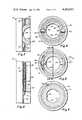
- FIGS. 4, 5 and 6are transverse sectional views taken respectively through 4--4, 5--5 and 6--6 of FIG. 2.
- FIG. 7is a fragmentary quarter sectional view corresponding to the lower portion of FIG. 2, the ball valve being shown in a closed position and showing the lock-open safety tube engaging the valve.
- FIG. 8is a fragmentary sectional view corresponding to FIG. 7, showing the ball valve in its open position and with the safety tube received in the valve and maintaining the valve in its open position.
- FIG. 9is a fragmentary longitudinal quarter sectional view showing the valve arranged for use as a safety valve, the section being taken through 9--9 of FIG. 1, the valve being shown in its closed position.
- FIG. 10is a similar fragmentary longitudinal quarter sectional view of the safety valve, the valve being shown in its open position.
- FIG. 11is a fragmentary elevational view of the rotatable drilling fluid swivel stem, showing partly in section and partly in elevation a control fluid transfer assembly.
- FIG. 12is an enlarged fragmentary sectional view taken within circle 12 of FIG. 2 showing the ball valve displaced with respect to its valve seat to permit limited bypass of drilling fluid so as to effect equalization of pressure.
- FIG. 13is a fragmentary sectional view of the ball valve housing taken through 13--13 of FIG. 5, with the ball valve in elevation, showing the drilling fluid bypass.
- the kelly valvesare suspended from a conventional drilling fluid swivel 1 supported within a drilling derrick, not shown.
- the swivel 1includes a housing 2 and supporting bail 3. Extending downwardly from the housing 2 is a rotatable stem 4 on which is mounted a control fluid transfer assembly 5 shown in FIG. 11.
- the assembly 5includes an inner sleeve 6 and an outer sleeve 7 journalled by bearings 8 which enable the inner sleeve 6 to rotate with the stem 4 and the outer sleeve 7 to be fixed against rotation by a tie cable or chain 9. Between the bearings 8 is a pair of sealed annular chambers 10 communicating with control lines 11, 12, 13 and 14.
- a safety valve 15Secured to the stem 4, by conventional fittings, is a safety valve 15 which is connected by conventional fittings to the upper end of the drill kelly 16.
- the lower end of the drill kelly 16is joined to an anti-spillage valve 17 which in turn is secured to a drill string 18.
- the safety valve 15 and the anti-spillage valve 17are two embodiments of the present invention.
- FIGS. 2, 3, 4, 5 and 6,these views show the kelly valve employed as an anti-spillage valve 17.
- the valveincludes a cylindrical housing 19 joined by lower and upper joint couplings to the drill string 18 and to the drill kelly 16 by means of internal end fittings 20 and 21.
- Extending upwardly from the end fitting 20is a valve journal sleeve 22 in contact with the cylindrical housing 19 and in longitudinal relation therewith by means of a split retaining ring 23 joining the journal sleeve 22 to the end fitting 21.
- the sleeve 22is provided with an internal rib 24, intermediate to its ends, and above the rib is provided with diametrically disposed axially extending slots 25.
- journal sleeve 22Adjacent to the retaining ring 23, the journal sleeve 22 is provided with a pair of diametrically disposed perforations 26 which receive journal pins 27 having radially inwardly extending shanks 28 of reduced diameter.
- the shanks 28form journals for the ball valve 29.
- the ball valveis provided with a shallow polygonal boss 30 surrounding one of the shanks 28. The boss serves to secure a pinion gear 31 to the valve 29.
- the sleeve 22is provided with slots 32 which clear the pinion gear 31 and expose the periphery thereof for engagement.
- the internal end fitting 21is provided with a spherical zone which forms a bearing and seal area 33 engaged by the ball valve 29.
- the seal area 33contains an O-ring seal 33a.
- a gear sleeve 34Disposed at the upper side of the ball valve, as viewed in FIGS. 2 and 3, there is provided a gear sleeve 34, having at its lower end a drive gear 35, engaging the pinion gear 31. Adjacent the drive gear 35, the gear sleeve 34 includes a spherical zone 36, which clears the ball valve 29.
- the gear sleeve 34extends axially upward from the ball valve 29, is retained by the internal rib 24 and is provided with a pair of diametrically disposed helical drive slots 37.
- the radially outer ends of the drive pins 39are recieved in the axially extending slots 25 whereas the radially inner ends of the drive pins 39 are received in the helical drive slots 37.
- the drive sleeve 38is provided with an internal flange 40 confronting the upper extremity of the gear sleeve 34.
- the radially inner extremity of the flange 40is provided with an axial or upward extension sleeve 41 which forms a sliding fit with the radially inner surface of the upper internal end fitting 21.
- a spring 42is interposed between the upper end fitting 21 and the internal flange 40.
- the extension sleeve 41is relatively thin and its upper end provides a pressure surface 43 of small area which is opposed by the substantially greater pressure surface 44 of the internal flange 40 so that fluid pressure within the sleeve 38 exerts a net upward force on the sleeve 38 opposing the spring 42.
- the radially inner surface 45 of the extension 41, the radially inner surface 46 of the gear sleeve 34 and the radially inner surface 47 of the end fitting 20are of equal diameter and the ball valve 29 is provided with a transverse bore 48 of equal diameter.
- the drive kelly 16 and drill string 18are disposed at opposite ends of the anti-spillage valve 17.
- the internal pressureexerts a force on the piston or pressure face 44 less 43, as shown in FIG. 3, whereby the ball valve is moved to and held in its open position.
- the spring 42urges the intermediate sleeve 38 downward from the position shown in FIG. 2, causing the ball valve 29 to be turned to its closed position shown in FIG. 2. Because the drilling fluid is shut off prior to disconnecting the drill string 18 and the drilling fluid pump is again activated after the new section of pipe is added to the drill string the anti-spillage valve opens and closes automatically.
- FIGS. 9 and 10it is useful to provide external control for the kelly valve. This may be accomplished by inverting the valve, as shown in FIGS. 9 and 10 to function as the safety valve 15 and provide for external control rather than internal control. Most of the parts are identical in both the anti-spillage valve 17, and the safety valve 15, and bear the same numerical indicia.
- the extension 41is increased in wall thickness as indicated by 41a, so as to provide a neutralized pressure end surface 44a.
- the internal flange 40is provided with an external flange 40a which engages the inner surface of the housing 19 and forms with the internal end fitting 21, the opposite ends of pressure fluid chamber 51 having a pressure fluid port 52 joined to the control line 11.
- An opposing pressure fluid chamber 53is formed with sleeve 34, journal sleeve 22, and housing 19 which is provided with a pressure fluid port 54 joined to the control line 12.
- control fluidmay be remotely controlled from the derrick floor manually or may be controlled automatically. For example, is excess drilling fluid pressure develops in the drill string, this may be sensed in the fluid supply line by automatic means, not shown, to cause a switching of the control fluid resulting in a movement of the valve from its open position to its closed position.
- the spring 42will close the valve automatically, thus providing the safety protection its name implies.
- An alternate method of controlling the safety valvewould be to sense the drilling fluid pressure on a pressure face 44b by further modifying 41a so that the outer diameter of extension sleeve 41a would be larger in area than the opposing area of 44a.
- This "sensed" drilling fluid pressurewould be transfered by piston 40a to the control fluid in chamber 53 holding the valve open against the force of spring 42.
- This increase of control pressure in lines 12 and 14would, by an automatic means at a predetermined pressure, switch the control fluid to cause the valve to close.
Landscapes
- Engineering & Computer Science (AREA)
- Life Sciences & Earth Sciences (AREA)
- Geology (AREA)
- Mining & Mineral Resources (AREA)
- Physics & Mathematics (AREA)
- Environmental & Geological Engineering (AREA)
- Fluid Mechanics (AREA)
- General Life Sciences & Earth Sciences (AREA)
- Geochemistry & Mineralogy (AREA)
- Mechanical Engineering (AREA)
- Earth Drilling (AREA)
- Taps Or Cocks (AREA)
Abstract
Description
This invention is related to U.S. Pat. No. 3,915,220; and U.S. Pat. No. 4,050,512, which are for tools connected to drill pipe and lowered down an oil well to test the formation reservoir; whereas the present invention is arranged for installation at an end of a drill kelly, and is summarized in the following objects:
First, to provide a kelly valve structure, which, with a minimum change in parts, may be installed at the lower end of a drill kelly to prevent spillage of mud from the kelly onto the derrick floor when the drill string is being disconnected; or, may be installed at the upper end of the drill kelly to close automatically and stop reverse flow from the drill string, thereby serving as a blow out preventor.
Second, to provide a kelly valve structure, which, when installed at the lower end of the drill kelly and subjected to low pressure existing during connection of the drill string to the kelly or disconnection therefrom, automatically opens in response to the increased drilling fluid pressure established upon resumption of drilling, and thus functions as an anti-spillage valve.
Third, to provide a kelly valve structure which, when installed at the upper end of the drill kelly and subjected to excessive pressure in the drill string is caused to shut off completely and serve to prevent blow outs, and thus serve as a safety valve.
Fourth, to provide a kelly valve structure, including a novelly arranged ball valve, which not only is rotatable between an open and a closed position, but also is axially movable in response to line pressure, when in its closed position, to bypass well fluid to equalize or reduce pressure differential across the valve.
FIG. 1 is an exploded view showing a supporting swivel, a drilling kelly and drill pipe with a safety valve, an anti-spillage valve, disposed respectively at the upper and lower ends of the drill kelly.
FIG. 2 is a fragmentary longitudinal quarter sectional view taken essentially through 2--2 of FIG. 1, showing the anti-spillage valve used at the lower end of the kelly, the valve being shown in its closed position.
FIG. 3 is a longitudinal fragmentary quarter sectional view corresponding to FIG. 2, showing the valve in its open position.
FIGS. 4, 5 and 6 are transverse sectional views taken respectively through 4--4, 5--5 and 6--6 of FIG. 2.
FIG. 7 is a fragmentary quarter sectional view corresponding to the lower portion of FIG. 2, the ball valve being shown in a closed position and showing the lock-open safety tube engaging the valve.
FIG. 8 is a fragmentary sectional view corresponding to FIG. 7, showing the ball valve in its open position and with the safety tube received in the valve and maintaining the valve in its open position.
FIG. 9 is a fragmentary longitudinal quarter sectional view showing the valve arranged for use as a safety valve, the section being taken through 9--9 of FIG. 1, the valve being shown in its closed position.
FIG. 10 is a similar fragmentary longitudinal quarter sectional view of the safety valve, the valve being shown in its open position.
FIG. 11 is a fragmentary elevational view of the rotatable drilling fluid swivel stem, showing partly in section and partly in elevation a control fluid transfer assembly.
FIG. 12 is an enlarged fragmentary sectional view taken withincircle 12 of FIG. 2 showing the ball valve displaced with respect to its valve seat to permit limited bypass of drilling fluid so as to effect equalization of pressure.
FIG. 13 is a fragmentary sectional view of the ball valve housing taken through 13--13 of FIG. 5, with the ball valve in elevation, showing the drilling fluid bypass.
Referring to FIG. 1, the kelly valves are suspended from a conventionaldrilling fluid swivel 1 supported within a drilling derrick, not shown. Theswivel 1 includes ahousing 2 and supportingbail 3. Extending downwardly from thehousing 2 is arotatable stem 4 on which is mounted a controlfluid transfer assembly 5 shown in FIG. 11.
Theassembly 5 includes aninner sleeve 6 and an outer sleeve 7 journalled by bearings 8 which enable theinner sleeve 6 to rotate with thestem 4 and the outer sleeve 7 to be fixed against rotation by a tie cable orchain 9. Between the bearings 8 is a pair of sealedannular chambers 10 communicating withcontrol lines
Secured to thestem 4, by conventional fittings, is asafety valve 15 which is connected by conventional fittings to the upper end of thedrill kelly 16. The lower end of thedrill kelly 16 is joined to ananti-spillage valve 17 which in turn is secured to adrill string 18. Thesafety valve 15 and theanti-spillage valve 17 are two embodiments of the present invention.
Referring to FIGS. 2, 3, 4, 5 and 6, these views show the kelly valve employed as ananti-spillage valve 17.
The valve includes acylindrical housing 19 joined by lower and upper joint couplings to thedrill string 18 and to the drill kelly 16 by means ofinternal end fittings valve journal sleeve 22 in contact with thecylindrical housing 19 and in longitudinal relation therewith by means of a split retainingring 23 joining thejournal sleeve 22 to the end fitting 21. Thesleeve 22 is provided with aninternal rib 24, intermediate to its ends, and above the rib is provided with diametrically disposed axially extendingslots 25.
Adjacent to theretaining ring 23, thejournal sleeve 22 is provided with a pair of diametrically disposedperforations 26 which receivejournal pins 27 having radially inwardly extendingshanks 28 of reduced diameter. Theshanks 28 form journals for theball valve 29. The ball valve is provided with a shallowpolygonal boss 30 surrounding one of theshanks 28. The boss serves to secure apinion gear 31 to thevalve 29. Thesleeve 22 is provided withslots 32 which clear thepinion gear 31 and expose the periphery thereof for engagement. Theinternal end fitting 21 is provided with a spherical zone which forms a bearing andseal area 33 engaged by theball valve 29. Theseal area 33 contains an O-ring seal 33a. Disposed at the upper side of the ball valve, as viewed in FIGS. 2 and 3, there is provided agear sleeve 34, having at its lower end adrive gear 35, engaging thepinion gear 31. Adjacent thedrive gear 35, thegear sleeve 34 includes aspherical zone 36, which clears theball valve 29.
Thegear sleeve 34 extends axially upward from theball valve 29, is retained by theinternal rib 24 and is provided with a pair of diametrically disposedhelical drive slots 37. Located between theouter sleeve 22 and thegear sleeve 34 is an intermediate ordrive sleeve 38, having a pair of diametrically disposeddrive pins 39. The radially outer ends of thedrive pins 39 are recieved in the axially extendingslots 25 whereas the radially inner ends of thedrive pins 39 are received in thehelical drive slots 37.
Above thegear sleeve 34 thedrive sleeve 38 is provided with aninternal flange 40 confronting the upper extremity of thegear sleeve 34. The radially inner extremity of theflange 40 is provided with an axial orupward extension sleeve 41 which forms a sliding fit with the radially inner surface of the upper internal end fitting 21. Aspring 42 is interposed between the upper end fitting 21 and theinternal flange 40. Theextension sleeve 41 is relatively thin and its upper end provides a pressure surface 43 of small area which is opposed by the substantiallygreater pressure surface 44 of theinternal flange 40 so that fluid pressure within thesleeve 38 exerts a net upward force on thesleeve 38 opposing thespring 42.
The radiallyinner surface 45 of theextension 41, the radiallyinner surface 46 of thegear sleeve 34 and the radiallyinner surface 47 of theend fitting 20 are of equal diameter and theball valve 29 is provided with atransverse bore 48 of equal diameter.
When the kelly valve is utilized as ananti-spillage valve 17, operation is as follows:
The drive kelly 16 anddrill string 18 are disposed at opposite ends of theanti-spillage valve 17. When drilling fluid is supplied under pressure through the swivel, the kelly, and the valve to the drill string, the internal pressure exerts a force on the piston orpressure face 44 less 43, as shown in FIG. 3, whereby the ball valve is moved to and held in its open position. When the pressure of the drilling fluid is reduced for the purpose of adding a section of pipe to thedrill string 18, thespring 42 urges theintermediate sleeve 38 downward from the position shown in FIG. 2, causing theball valve 29 to be turned to its closed position shown in FIG. 2. Because the drilling fluid is shut off prior to disconnecting thedrill string 18 and the drilling fluid pump is again activated after the new section of pipe is added to the drill string the anti-spillage valve opens and closes automatically.
Referring to FIGS. 12 and 13, operating conditions occur in which it is desired to provide a bypass around the ball valve although the valve is in its closed position. This is accomplished by providing a limited amount of relative longitudinal travel between the internal end fitting 20 and theball valve 29 as shown in FIGS. 12 and 13.
Referring to FIGS. 7 and 8, it sometimes occurs that the drill stem becomes stuck while drilling a well with the lower end of the drill kelly inaccessible because it is below the rotary table. Under such conditions it is desirable to lock the anti-spillage valve in its open position. When such conditions occur the kelly is disconnected at its upper end and a lock-open safety tube 49, dimensioned to fit freely within the kelly, is dropped through the kelly and comes to rest on the closed valve, as shown in FIG. 7. In order to utilize thetube 49, theend fitting 20 is provided below theball valve 29 with a set ofinternal stop lugs 50. Whereupon drilling fluid pressure is reestablished momentarily permitting thetube 49 to enter theopen ball valve 29, as shown in FIG. 8, and come to rest on thestop lugs 50. The valve is rendered inoperative and the drilling string may be manipulated to overcome whatever problem has arisen, including the lowering of tools through thesafety tube 49.
Referring to FIGS. 9 and 10, it is useful to provide external control for the kelly valve. This may be accomplished by inverting the valve, as shown in FIGS. 9 and 10 to function as thesafety valve 15 and provide for external control rather than internal control. Most of the parts are identical in both theanti-spillage valve 17, and thesafety valve 15, and bear the same numerical indicia.
The modifications are as follows:
Theextension 41 is increased in wall thickness as indicated by 41a, so as to provide a neutralized pressure end surface 44a. However, theinternal flange 40 is provided with an external flange 40a which engages the inner surface of thehousing 19 and forms with the internal end fitting 21, the opposite ends ofpressure fluid chamber 51 having apressure fluid port 52 joined to thecontrol line 11. An opposingpressure fluid chamber 53 is formed withsleeve 34,journal sleeve 22, andhousing 19 which is provided with apressure fluid port 54 joined to thecontrol line 12.
Operation of the kelly valve when used as asafety valve 15, is as follows:
Assuming theball valve 29 is in its closed position, as shown in FIG. 9, the application of pressure control fluid throughline 12 to thepressure fluid chamber 53 causes the intermediate sleeve to move from the closed position shown in FIG. 9 to the open position shown in FIG. 10. This movement causes a 90° rotation of theball valve 29. When the valve is in its open position a supply of pressure fluid throughcontrol line 11 into thepressure fluid chamber 51 causes thepressure fluid chamber 51 to extend, reversing the movement of theintermediate sleeve 38 so as to close theball valve 29.
Except for the force exerted by thespring 42, movement of the valve is dependent entirely upon the control pressure as applied to thechambers control lines control lines spring 42 will close the valve automatically, thus providing the safety protection its name implies.
An alternate method of controlling the safety valve, not shown, would be to sense the drilling fluid pressure on a pressure face 44b by further modifying 41a so that the outer diameter ofextension sleeve 41a would be larger in area than the opposing area of 44a. This "sensed" drilling fluid pressure would be transfered by piston 40a to the control fluid inchamber 53 holding the valve open against the force ofspring 42. This increase of control pressure inlines
It will be noted that appropriate seals, such as O-rings are provided where needed.
Having fully described my invention it is to be noted that I am not to be limited to the details herein set forth, but that my invention is of the full scope of the appended claims.
Claims (12)
1. A valve structure for installation in a drilling fluid line at an end of a drill kelly to control flow of drill fluid therethrough, comprising:
a. a tubular housing having a fitting at each end for removably installing the housing at either end of the drill kelly;
b. a journal sleeve mounted in the housing and having diametrically disposed journal pins;
c. a ball valve rotatable on the journal pins and having a bore movable between an open position coaxial with the journal sleeve and a transverse closed position;
d. a gear sleeve coaxial with the journal sleeve;
e. a gear drive disposed between the ball valve and gear sleeve;
f. a drive sleeve interposed between the journal sleeve and gear sleeve including radial drive pins protruding radially inwardly and radially outward therefrom;
g. and longitudinal grooves provided in the journal sleeve and gear sleeve, one of the grooves being helical whereby longitudinal movement of the sleeves causes the gear drive to effect rotation of the ball valve between its open and closed positions.
2. A valve structure, as defined in claim 1, which is arranged for installation between the lower end of the drill kelly and the portion of the drilling fluid line receiving drilling fluid therefrom, wherein:
a. the drive sleeve includes a piston element exposed to fluid pressure upstream of the ball valve, exerting a force tending to move the ball valve from its closed to its open position;
b. and a spring operable to move the ball valve from its open to its closed position on termination of fluid pressure to prevent drainage of fluid from the drill kelly upon disconnection of the valve structure from the drilling fluid line.
3. A valve structure, as defined in claim 1, which is arranged for installation between the upper end of the drill kelly and the portion of the drilling fluid line supplying drilling fluid thereto, wherein:
a. the drive sleeve includes piston elements exposed to opposed pressure chambers;
b. and means is provided to supply pressure fluid to the chambers to effect movement of the ball valve between its open and closed positions.
4. A valve structure, as defined in claim 1, wherein:
a. the ball valve is axially engageable with a valve seat;
b. means is provided to permit relative axial movement between the ball valve and valve seat to effect bypass of fluid while the ball valve is otherwise in its closed position.
5. A valve structure, as defined in claim 1, wherein:
a. internal stop lugs are positioned contiguous to the bore of the ball valve;
b. and a tubular safety sleeve dimensioned to pass through the bore of the ball valve and engage the stop lugs to maintain the ball valve in its open position.
6. A valve structure for installation in a drilling fluid line at an end of a drill kelly to control flow of drill fluid therethrough, comprising:
a. a tubular housing having a fitting at each end for removably installing the housing in a drilling fluid line at either end of the drill kelly;
b. an inner sleeve having a bore coaxial with the housing and including an axially directed drive gear;
c. a longitudinally movable means for effecting a predetermined arcuate movement of the inner sleeve and its drive gear;
d. a ball valve having a driven gear engageable by the drive gear, the ball valve having a bore oriented for movement between an open position aligned with the bore of the inner sleeve and a transverse closed position;
e. means for activating the longitudinally movable means to effect movement of the ball valve between its open and its closed position;
f. the valve structure is adapted to be interposed between the lower end of the drill kelly and the drilling fluid line;
g. and the activating means includes a pressure responsive element operable to maintain the ball valve open when the drill kelly is connected to the drilling fluid line and is subjected to a predetermined operating pressure therein, and a spring, operable upon a predetermined reduced pressure to close the ball valve thereby to permit disconnection of the drill kelly from the drilling fluid line.
7. A valve structure for installation in a drilling fluid line at an end of a drill kelly to control flow of drill fluid therethrough, comprising:
a. a tubular housing having a fitting at each end for removably installing the housing in a drilling fluid line at either end of the drill kelly;
b. an inner sleeve having a bore coaxial with the housing and including an axially directed drive gear;
c. a longitudinally movable means for effecting a predetermined arcuate movement of the inner sleeve and its drive gear;
d. a ball valve having a driven gear engageable by the drive gear, the ball valve having a bore oriented for movement between an open position aligned with the bore of the inner sleeve and a transverse closed position;
e. means for activating the longitudinally movable means to effect movement of the ball valve between its open and its closed position;
f. the valve structure is adapted to be interposed between the upper end of the drill kelly and the drilling fluid feed line;
g. and the activating means includes a pair of externally accessible opposed pressure chambers.
8. A valve structure for installation in a drilling fluid line at an end of a drill kelly to control flow of drill fluid therethrough, comprising:
a. a tubular housing having a fitting at each end for removably installing the housing in a drilling fluid line at either end of the drill kelly;
b. an inner sleeve having a bore coaxial with the housing and including an axially directed drive gear;
c. a longitudinally movable means for effecting a predetermined arcuate movement of the inner sleeve and its drive gear;
d. a ball valve having a driven gear engageable by the drive gear, the ball valve having a bore oriented for movement between an open position aligned with the bore of the inner sleeve and a transverse closed position;
e. means for activating the longitudinally movable means to effect movement of the ball valve between its open and its closed position;
f. a tube is insertable through the inner sleeve for engagement with the ball valve when in its closed position, the tube being further slidable through the ball valve upon movement of the ball valve to its open position;
g. and an internal projection is disposed beyond the ball valve to maintain the tube in a position wherein the ball valve is maintained open.
9. A valve structure, comprising:
a. a tubular housing;
b. tool joint couplings disposed at opposite ends of the housing for interposing the tubular housing between a drill kelly and a drilling fluid line;
c. a journal sleeve fixed within the housing near one end thereof;
d. a pair of diametrically disposed journal pins carried by the journal sleeve;
e. a spherical valve carried by the journal pins having a bore rotatable between a closed and an open position with respect to the journal sleeve;
f. a gear sleeve within the journal sleeve and confronting the spherical valve;
g. the gear sleeve and spherical valve having mating driving and driven gears operable, upon partial rotation of the gear sleeve, to turn the spherical valve between a closed position and an open position;
h. drive pins carried by the drive sleeve, and grooves, including axial grooves and helical grooves carried by the journal sleeve and gear sleeve operable upon axial movement of the drive sleeve to effect corresponding opening and closing of the spherical valve;
i. and means for effecting axial movement of the drive sleeve.
10. A valve structure, as defined in claim 9, wherein said means for effecting axial movement of the drive sleeve comprises:
a. confronting an axially directed surface of the drive sleeve exposed to pressure from within the housing to effect axial movement of the drive sleeve in one direction;
b. and a spring to effect axial movement of the drive sleeve in the opposite direction.
11. A valve structure, as defined in claim 9, wherein said means for effecting axial movement of the drive sleeve comprises:
a. an opposed pair of axially expansible and contractable pressure chambers;
b. and an external source of pressure fluid for said chambers.
12. A valve structure, as defined in claim 9, wherein:
a. a safety tube is insertable through the gear sleeve for engagement with the spherical valve shen in its closed position, the tube being further slidable through the spherical valve upon movement of the spherical valve to its open position;
b. and means is provided to retain the tube within the spherical valve, thereby to maintain the spherical valve in its open position.
Priority Applications (2)
| Application Number | Priority Date | Filing Date | Title |
|---|---|---|---|
| US06/053,854US4262693A (en) | 1979-07-02 | 1979-07-02 | Kelly valve |
| CA000355203ACA1140107A (en) | 1979-07-02 | 1980-07-02 | Kelly valve |
Applications Claiming Priority (1)
| Application Number | Priority Date | Filing Date | Title |
|---|---|---|---|
| US06/053,854US4262693A (en) | 1979-07-02 | 1979-07-02 | Kelly valve |
Publications (1)
| Publication Number | Publication Date |
|---|---|
| US4262693Atrue US4262693A (en) | 1981-04-21 |
Family
ID=21986998
Family Applications (1)
| Application Number | Title | Priority Date | Filing Date |
|---|---|---|---|
| US06/053,854Expired - LifetimeUS4262693A (en) | 1979-07-02 | 1979-07-02 | Kelly valve |
Country Status (2)
| Country | Link |
|---|---|
| US (1) | US4262693A (en) |
| CA (1) | CA1140107A (en) |
Cited By (91)
| Publication number | Priority date | Publication date | Assignee | Title |
|---|---|---|---|---|
| US4359932A (en)* | 1977-12-15 | 1982-11-23 | Exxon Production Research Co. | Hydraulic actuator |
| FR2523635A1 (en)* | 1982-03-17 | 1983-09-23 | Bretagne Atel Chantiers | DEVICE FOR MOUNTING A DRILL ROD TRAIN AND FOR TRAINING IN ROTATION AND TRANSLATION |
| US4519576A (en)* | 1983-12-15 | 1985-05-28 | Winegeart Mitchell E | Oil well safety valve for use with drill pipe |
| US4535968A (en)* | 1983-11-16 | 1985-08-20 | Otis Engineering Corporation | Valve |
| US4537383A (en)* | 1984-10-02 | 1985-08-27 | Otis Engineering Corporation | Valve |
| US4565213A (en)* | 1980-10-28 | 1986-01-21 | Bernhardt & Frederick Co., Inc. | Ball valve device with hold-open tube |
| US4570724A (en)* | 1984-08-23 | 1986-02-18 | Gray Tool Company | Stepwise rotary actuator |
| US4795128A (en)* | 1988-03-01 | 1989-01-03 | Vetco Gray Inc. | Gate type kelly cock valve |
| US5501242A (en)* | 1992-06-24 | 1996-03-26 | Expro North Sea Limited | Pressure relief valve |
| US5509442A (en)* | 1995-03-28 | 1996-04-23 | Claycomb; Jackson R. | Mud saver valve |
| US5558121A (en)* | 1995-06-07 | 1996-09-24 | Aeroquip Corporation | Fluid actuated ball check valve assembly |
| US5836395A (en)* | 1994-08-01 | 1998-11-17 | Weatherford/Lamb, Inc. | Valve for wellbore use |
| US6289911B1 (en)* | 1999-04-16 | 2001-09-18 | Smith International, Inc. | Mud saver kelly valve |
| US6412554B1 (en) | 2000-03-14 | 2002-07-02 | Weatherford/Lamb, Inc. | Wellbore circulation system |
| US6598501B1 (en) | 1999-01-28 | 2003-07-29 | Weatherford/Lamb, Inc. | Apparatus and a method for facilitating the connection of pipes |
| US20030164276A1 (en)* | 2000-04-17 | 2003-09-04 | Weatherford/Lamb, Inc. | Top drive casing system |
| US20030221519A1 (en)* | 2000-03-14 | 2003-12-04 | Haugen David M. | Methods and apparatus for connecting tubulars while drilling |
| US6662886B2 (en)* | 2000-04-03 | 2003-12-16 | Larry R. Russell | Mudsaver valve with dual snap action |
| US6684737B1 (en) | 1999-01-28 | 2004-02-03 | Weatherford/Lamb, Inc. | Power tong |
| US20040045717A1 (en)* | 2002-09-05 | 2004-03-11 | Haugen David M. | Method and apparatus for reforming tubular connections |
| US6745646B1 (en) | 1999-07-29 | 2004-06-08 | Weatherford/Lamb, Inc. | Apparatus and method for facilitating the connection of pipes |
| US20040124010A1 (en)* | 2002-12-30 | 2004-07-01 | Galloway Gregory G. | Drilling with concentric strings of casing |
| US20040124011A1 (en)* | 2002-12-31 | 2004-07-01 | Gledhill Andrew D. | Expandable bit with a secondary release device |
| US6814149B2 (en) | 1999-11-26 | 2004-11-09 | Weatherford/Lamb, Inc. | Apparatus and method for positioning a tubular relative to a tong |
| US20040237726A1 (en)* | 2002-02-12 | 2004-12-02 | Schulze Beckinghausen Joerg E. | Tong |
| US6854533B2 (en) | 2002-12-20 | 2005-02-15 | Weatherford/Lamb, Inc. | Apparatus and method for drilling with casing |
| US6868906B1 (en) | 1994-10-14 | 2005-03-22 | Weatherford/Lamb, Inc. | Closed-loop conveyance systems for well servicing |
| US20050061112A1 (en)* | 2003-09-19 | 2005-03-24 | Weatherford Lamb, Inc. | Adapter frame for a power frame |
| US20050076744A1 (en)* | 2003-10-08 | 2005-04-14 | Weatherford/Lamb, Inc. | Apparatus and methods for connecting tubulars |
| US20050077743A1 (en)* | 2003-10-08 | 2005-04-14 | Bernd-Georg Pietras | Tong assembly |
| US6896075B2 (en) | 2002-10-11 | 2005-05-24 | Weatherford/Lamb, Inc. | Apparatus and methods for drilling with casing |
| US6899186B2 (en) | 2002-12-13 | 2005-05-31 | Weatherford/Lamb, Inc. | Apparatus and method of drilling with casing |
| US20060000600A1 (en)* | 1998-08-24 | 2006-01-05 | Bernd-Georg Pietras | Casing feeder |
| US6994176B2 (en) | 2002-07-29 | 2006-02-07 | Weatherford/Lamb, Inc. | Adjustable rotating guides for spider or elevator |
| US7004264B2 (en) | 2002-03-16 | 2006-02-28 | Weatherford/Lamb, Inc. | Bore lining and drilling |
| US7013997B2 (en) | 1994-10-14 | 2006-03-21 | Weatherford/Lamb, Inc. | Methods and apparatus for cementing drill strings in place for one pass drilling and completion of oil and gas wells |
| US7028586B2 (en) | 2000-02-25 | 2006-04-18 | Weatherford/Lamb, Inc. | Apparatus and method relating to tongs, continous circulation and to safety slips |
| US7028585B2 (en) | 1999-11-26 | 2006-04-18 | Weatherford/Lamb, Inc. | Wrenching tong |
| US7036610B1 (en) | 1994-10-14 | 2006-05-02 | Weatherford / Lamb, Inc. | Apparatus and method for completing oil and gas wells |
| US7040420B2 (en) | 1994-10-14 | 2006-05-09 | Weatherford/Lamb, Inc. | Methods and apparatus for cementing drill strings in place for one pass drilling and completion of oil and gas wells |
| US7073598B2 (en) | 2001-05-17 | 2006-07-11 | Weatherford/Lamb, Inc. | Apparatus and methods for tubular makeup interlock |
| US20060151181A1 (en)* | 2005-01-12 | 2006-07-13 | David Shahin | One-position fill-up and circulating tool |
| US7090021B2 (en) | 1998-08-24 | 2006-08-15 | Bernd-Georg Pietras | Apparatus for connecting tublars using a top drive |
| US7090254B1 (en) | 1999-04-13 | 2006-08-15 | Bernd-Georg Pietras | Apparatus and method aligning tubulars |
| US20060180315A1 (en)* | 2005-01-18 | 2006-08-17 | David Shahin | Top drive torque booster |
| US7093675B2 (en) | 2000-08-01 | 2006-08-22 | Weatherford/Lamb, Inc. | Drilling method |
| US7096982B2 (en) | 2003-02-27 | 2006-08-29 | Weatherford/Lamb, Inc. | Drill shoe |
| US7100713B2 (en) | 2000-04-28 | 2006-09-05 | Weatherford/Lamb, Inc. | Expandable apparatus for drift and reaming borehole |
| US7100710B2 (en) | 1994-10-14 | 2006-09-05 | Weatherford/Lamb, Inc. | Methods and apparatus for cementing drill strings in place for one pass drilling and completion of oil and gas wells |
| US7108084B2 (en) | 1994-10-14 | 2006-09-19 | Weatherford/Lamb, Inc. | Methods and apparatus for cementing drill strings in place for one pass drilling and completion of oil and gas wells |
| US7117957B2 (en) | 1998-12-22 | 2006-10-10 | Weatherford/Lamb, Inc. | Methods for drilling and lining a wellbore |
| US7128161B2 (en) | 1998-12-24 | 2006-10-31 | Weatherford/Lamb, Inc. | Apparatus and methods for facilitating the connection of tubulars using a top drive |
| US7128154B2 (en) | 2003-01-30 | 2006-10-31 | Weatherford/Lamb, Inc. | Single-direction cementing plug |
| US7137454B2 (en) | 1998-07-22 | 2006-11-21 | Weatherford/Lamb, Inc. | Apparatus for facilitating the connection of tubulars using a top drive |
| US7140445B2 (en) | 1997-09-02 | 2006-11-28 | Weatherford/Lamb, Inc. | Method and apparatus for drilling with casing |
| US7147068B2 (en) | 1994-10-14 | 2006-12-12 | Weatherford / Lamb, Inc. | Methods and apparatus for cementing drill strings in place for one pass drilling and completion of oil and gas wells |
| US7188687B2 (en) | 1998-12-22 | 2007-03-13 | Weatherford/Lamb, Inc. | Downhole filter |
| US7191840B2 (en) | 2003-03-05 | 2007-03-20 | Weatherford/Lamb, Inc. | Casing running and drilling system |
| US7213656B2 (en) | 1998-12-24 | 2007-05-08 | Weatherford/Lamb, Inc. | Apparatus and method for facilitating the connection of tubulars using a top drive |
| US7216727B2 (en) | 1999-12-22 | 2007-05-15 | Weatherford/Lamb, Inc. | Drilling bit for drilling while running casing |
| US7219744B2 (en) | 1998-08-24 | 2007-05-22 | Weatherford/Lamb, Inc. | Method and apparatus for connecting tubulars using a top drive |
| US7228901B2 (en) | 1994-10-14 | 2007-06-12 | Weatherford/Lamb, Inc. | Method and apparatus for cementing drill strings in place for one pass drilling and completion of oil and gas wells |
| US7264067B2 (en) | 2003-10-03 | 2007-09-04 | Weatherford/Lamb, Inc. | Method of drilling and completing multiple wellbores inside a single caisson |
| US20070215356A1 (en)* | 2006-03-17 | 2007-09-20 | Gerald Leeb | Dual check valve |
| US7284617B2 (en) | 2004-05-20 | 2007-10-23 | Weatherford/Lamb, Inc. | Casing running head |
| US20070251701A1 (en)* | 2006-04-27 | 2007-11-01 | Michael Jahn | Torque sub for use with top drive |
| US7303022B2 (en) | 2002-10-11 | 2007-12-04 | Weatherford/Lamb, Inc. | Wired casing |
| US7311148B2 (en) | 1999-02-25 | 2007-12-25 | Weatherford/Lamb, Inc. | Methods and apparatus for wellbore construction and completion |
| US7325610B2 (en) | 2000-04-17 | 2008-02-05 | Weatherford/Lamb, Inc. | Methods and apparatus for handling and drilling with tubulars or casing |
| US7334650B2 (en) | 2000-04-13 | 2008-02-26 | Weatherford/Lamb, Inc. | Apparatus and methods for drilling a wellbore using casing |
| US7360594B2 (en) | 2003-03-05 | 2008-04-22 | Weatherford/Lamb, Inc. | Drilling with casing latch |
| US7370707B2 (en) | 2003-04-04 | 2008-05-13 | Weatherford/Lamb, Inc. | Method and apparatus for handling wellbore tubulars |
| US20080125876A1 (en)* | 2006-11-17 | 2008-05-29 | Boutwell Doyle F | Top drive interlock |
| US7413020B2 (en) | 2003-03-05 | 2008-08-19 | Weatherford/Lamb, Inc. | Full bore lined wellbores |
| US7503397B2 (en) | 2004-07-30 | 2009-03-17 | Weatherford/Lamb, Inc. | Apparatus and methods of setting and retrieving casing with drilling latch and bottom hole assembly |
| US7506564B2 (en) | 2002-02-12 | 2009-03-24 | Weatherford/Lamb, Inc. | Gripping system for a tong |
| US7509722B2 (en) | 1997-09-02 | 2009-03-31 | Weatherford/Lamb, Inc. | Positioning and spinning device |
| US7617866B2 (en) | 1998-08-24 | 2009-11-17 | Weatherford/Lamb, Inc. | Methods and apparatus for connecting tubulars using a top drive |
| US7650944B1 (en) | 2003-07-11 | 2010-01-26 | Weatherford/Lamb, Inc. | Vessel for well intervention |
| US7874352B2 (en) | 2003-03-05 | 2011-01-25 | Weatherford/Lamb, Inc. | Apparatus for gripping a tubular on a drilling rig |
| EP2375273A1 (en) | 2010-04-09 | 2011-10-12 | Leica Microsystems CMS GmbH | Fluorescence microscope and method for multiple positioning in a screening application |
| USRE42877E1 (en) | 2003-02-07 | 2011-11-01 | Weatherford/Lamb, Inc. | Methods and apparatus for wellbore construction and completion |
| WO2011143654A2 (en) | 2010-05-14 | 2011-11-17 | Gulfstream Services, Inc. | Method and apparatus for dropping a pump down plug or ball |
| US20120048562A1 (en)* | 2010-08-25 | 2012-03-01 | Weatherford/Lamb, Inc. | Self-Orienting Crossover Tool |
| US20130025711A1 (en)* | 2010-04-28 | 2013-01-31 | Larry Rayner Russell | Self Piloted Check Valve |
| US9309737B2 (en)* | 2012-06-08 | 2016-04-12 | Vetco Gray U.K. Limited | Rotational shear valve |
| US9309979B2 (en) | 2010-04-28 | 2016-04-12 | Larry Rayner Russell | Self piloted check valve |
| US10006262B2 (en)* | 2014-02-21 | 2018-06-26 | Weatherford Technology Holdings, Llc | Continuous flow system for drilling oil and gas wells |
| CN112431564A (en)* | 2020-11-30 | 2021-03-02 | 河北永明地质工程机械有限公司 | Valve and top drive slurry pipeline device |
| CN115596422A (en)* | 2022-12-16 | 2023-01-13 | 新疆石油管理局有限公司(Cn) | Shale oil directional fracturing device and method for coiled tubing horizontal well |
| WO2025106092A1 (en)* | 2023-11-13 | 2025-05-22 | Halliburton Energy Services, Inc. | Safety valve harnessing weight and gravity for fail-safe closure |
Citations (6)
| Publication number | Priority date | Publication date | Assignee | Title |
|---|---|---|---|---|
| US2322064A (en)* | 1941-12-22 | 1943-06-15 | Standard Oil Dev Co | Coring device |
| US3035808A (en)* | 1956-08-30 | 1962-05-22 | Hydril Co | Pressure responsive valve |
| US3583442A (en)* | 1968-12-23 | 1971-06-08 | Otis Eng Co | Rotary valves |
| US3915228A (en)* | 1975-01-27 | 1975-10-28 | Bernhardt F Giebeler | Well bore test and safety valve structure |
| US3993136A (en)* | 1975-08-25 | 1976-11-23 | Hydril Company | Apparatus for operating a closure element of a subsurface safety valve and method of using same |
| US4050512A (en)* | 1976-07-06 | 1977-09-27 | Bj-Hughes Inc. | Stroke actuated well testing tool |
- 1979
- 1979-07-02USUS06/053,854patent/US4262693A/ennot_activeExpired - Lifetime
- 1980
- 1980-07-02CACA000355203Apatent/CA1140107A/ennot_activeExpired
Patent Citations (6)
| Publication number | Priority date | Publication date | Assignee | Title |
|---|---|---|---|---|
| US2322064A (en)* | 1941-12-22 | 1943-06-15 | Standard Oil Dev Co | Coring device |
| US3035808A (en)* | 1956-08-30 | 1962-05-22 | Hydril Co | Pressure responsive valve |
| US3583442A (en)* | 1968-12-23 | 1971-06-08 | Otis Eng Co | Rotary valves |
| US3915228A (en)* | 1975-01-27 | 1975-10-28 | Bernhardt F Giebeler | Well bore test and safety valve structure |
| US3993136A (en)* | 1975-08-25 | 1976-11-23 | Hydril Company | Apparatus for operating a closure element of a subsurface safety valve and method of using same |
| US4050512A (en)* | 1976-07-06 | 1977-09-27 | Bj-Hughes Inc. | Stroke actuated well testing tool |
Cited By (140)
| Publication number | Priority date | Publication date | Assignee | Title |
|---|---|---|---|---|
| US4359932A (en)* | 1977-12-15 | 1982-11-23 | Exxon Production Research Co. | Hydraulic actuator |
| US4565213A (en)* | 1980-10-28 | 1986-01-21 | Bernhardt & Frederick Co., Inc. | Ball valve device with hold-open tube |
| FR2523635A1 (en)* | 1982-03-17 | 1983-09-23 | Bretagne Atel Chantiers | DEVICE FOR MOUNTING A DRILL ROD TRAIN AND FOR TRAINING IN ROTATION AND TRANSLATION |
| EP0089599A1 (en)* | 1982-03-17 | 1983-09-28 | Alsthom | Handling device for drilling rods |
| US4535968A (en)* | 1983-11-16 | 1985-08-20 | Otis Engineering Corporation | Valve |
| US4519576A (en)* | 1983-12-15 | 1985-05-28 | Winegeart Mitchell E | Oil well safety valve for use with drill pipe |
| US4570724A (en)* | 1984-08-23 | 1986-02-18 | Gray Tool Company | Stepwise rotary actuator |
| US4537383A (en)* | 1984-10-02 | 1985-08-27 | Otis Engineering Corporation | Valve |
| US4795128A (en)* | 1988-03-01 | 1989-01-03 | Vetco Gray Inc. | Gate type kelly cock valve |
| US5501242A (en)* | 1992-06-24 | 1996-03-26 | Expro North Sea Limited | Pressure relief valve |
| US5836395A (en)* | 1994-08-01 | 1998-11-17 | Weatherford/Lamb, Inc. | Valve for wellbore use |
| US7147068B2 (en) | 1994-10-14 | 2006-12-12 | Weatherford / Lamb, Inc. | Methods and apparatus for cementing drill strings in place for one pass drilling and completion of oil and gas wells |
| US7100710B2 (en) | 1994-10-14 | 2006-09-05 | Weatherford/Lamb, Inc. | Methods and apparatus for cementing drill strings in place for one pass drilling and completion of oil and gas wells |
| US7108084B2 (en) | 1994-10-14 | 2006-09-19 | Weatherford/Lamb, Inc. | Methods and apparatus for cementing drill strings in place for one pass drilling and completion of oil and gas wells |
| US7165634B2 (en) | 1994-10-14 | 2007-01-23 | Weatherford/Lamb, Inc. | Method and apparatus for cementing drill strings in place for one pass drilling and completion of oil and gas wells |
| US7048050B2 (en) | 1994-10-14 | 2006-05-23 | Weatherford/Lamb, Inc. | Method and apparatus for cementing drill strings in place for one pass drilling and completion of oil and gas wells |
| US7040420B2 (en) | 1994-10-14 | 2006-05-09 | Weatherford/Lamb, Inc. | Methods and apparatus for cementing drill strings in place for one pass drilling and completion of oil and gas wells |
| US7036610B1 (en) | 1994-10-14 | 2006-05-02 | Weatherford / Lamb, Inc. | Apparatus and method for completing oil and gas wells |
| US7013997B2 (en) | 1994-10-14 | 2006-03-21 | Weatherford/Lamb, Inc. | Methods and apparatus for cementing drill strings in place for one pass drilling and completion of oil and gas wells |
| US7228901B2 (en) | 1994-10-14 | 2007-06-12 | Weatherford/Lamb, Inc. | Method and apparatus for cementing drill strings in place for one pass drilling and completion of oil and gas wells |
| US6868906B1 (en) | 1994-10-14 | 2005-03-22 | Weatherford/Lamb, Inc. | Closed-loop conveyance systems for well servicing |
| US5509442A (en)* | 1995-03-28 | 1996-04-23 | Claycomb; Jackson R. | Mud saver valve |
| US5558121A (en)* | 1995-06-07 | 1996-09-24 | Aeroquip Corporation | Fluid actuated ball check valve assembly |
| US7509722B2 (en) | 1997-09-02 | 2009-03-31 | Weatherford/Lamb, Inc. | Positioning and spinning device |
| US7140445B2 (en) | 1997-09-02 | 2006-11-28 | Weatherford/Lamb, Inc. | Method and apparatus for drilling with casing |
| US7137454B2 (en) | 1998-07-22 | 2006-11-21 | Weatherford/Lamb, Inc. | Apparatus for facilitating the connection of tubulars using a top drive |
| US7665531B2 (en) | 1998-07-22 | 2010-02-23 | Weatherford/Lamb, Inc. | Apparatus for facilitating the connection of tubulars using a top drive |
| US7219744B2 (en) | 1998-08-24 | 2007-05-22 | Weatherford/Lamb, Inc. | Method and apparatus for connecting tubulars using a top drive |
| US7513300B2 (en) | 1998-08-24 | 2009-04-07 | Weatherford/Lamb, Inc. | Casing running and drilling system |
| US7617866B2 (en) | 1998-08-24 | 2009-11-17 | Weatherford/Lamb, Inc. | Methods and apparatus for connecting tubulars using a top drive |
| US20070051519A1 (en)* | 1998-08-24 | 2007-03-08 | Bernd-Georg Pietras | apparatus for connecting tubulars using a top drive |
| US7451826B2 (en) | 1998-08-24 | 2008-11-18 | Weatherford/Lamb, Inc. | Apparatus for connecting tubulars using a top drive |
| US7353880B2 (en) | 1998-08-24 | 2008-04-08 | Weatherford/Lamb, Inc. | Method and apparatus for connecting tubulars using a top drive |
| US7090021B2 (en) | 1998-08-24 | 2006-08-15 | Bernd-Georg Pietras | Apparatus for connecting tublars using a top drive |
| US20060000600A1 (en)* | 1998-08-24 | 2006-01-05 | Bernd-Georg Pietras | Casing feeder |
| US20070193751A1 (en)* | 1998-08-24 | 2007-08-23 | Bernd-Georg Pietras | Casing running and drilling system |
| US7669662B2 (en) | 1998-08-24 | 2010-03-02 | Weatherford/Lamb, Inc. | Casing feeder |
| US7117957B2 (en) | 1998-12-22 | 2006-10-10 | Weatherford/Lamb, Inc. | Methods for drilling and lining a wellbore |
| US7188687B2 (en) | 1998-12-22 | 2007-03-13 | Weatherford/Lamb, Inc. | Downhole filter |
| US7213656B2 (en) | 1998-12-24 | 2007-05-08 | Weatherford/Lamb, Inc. | Apparatus and method for facilitating the connection of tubulars using a top drive |
| US7128161B2 (en) | 1998-12-24 | 2006-10-31 | Weatherford/Lamb, Inc. | Apparatus and methods for facilitating the connection of tubulars using a top drive |
| US6598501B1 (en) | 1999-01-28 | 2003-07-29 | Weatherford/Lamb, Inc. | Apparatus and a method for facilitating the connection of pipes |
| US6684737B1 (en) | 1999-01-28 | 2004-02-03 | Weatherford/Lamb, Inc. | Power tong |
| US7311148B2 (en) | 1999-02-25 | 2007-12-25 | Weatherford/Lamb, Inc. | Methods and apparatus for wellbore construction and completion |
| US7090254B1 (en) | 1999-04-13 | 2006-08-15 | Bernd-Georg Pietras | Apparatus and method aligning tubulars |
| US6289911B1 (en)* | 1999-04-16 | 2001-09-18 | Smith International, Inc. | Mud saver kelly valve |
| US6745646B1 (en) | 1999-07-29 | 2004-06-08 | Weatherford/Lamb, Inc. | Apparatus and method for facilitating the connection of pipes |
| US20060179980A1 (en)* | 1999-11-26 | 2006-08-17 | Weatherford/Lamb, Inc. | Wrenching tong |
| US7028585B2 (en) | 1999-11-26 | 2006-04-18 | Weatherford/Lamb, Inc. | Wrenching tong |
| US6814149B2 (en) | 1999-11-26 | 2004-11-09 | Weatherford/Lamb, Inc. | Apparatus and method for positioning a tubular relative to a tong |
| US7861618B2 (en) | 1999-11-26 | 2011-01-04 | Weatherford/Lamb, Inc. | Wrenching tong |
| US7216727B2 (en) | 1999-12-22 | 2007-05-15 | Weatherford/Lamb, Inc. | Drilling bit for drilling while running casing |
| US7028586B2 (en) | 2000-02-25 | 2006-04-18 | Weatherford/Lamb, Inc. | Apparatus and method relating to tongs, continous circulation and to safety slips |
| US20030221519A1 (en)* | 2000-03-14 | 2003-12-04 | Haugen David M. | Methods and apparatus for connecting tubulars while drilling |
| US6668684B2 (en) | 2000-03-14 | 2003-12-30 | Weatherford/Lamb, Inc. | Tong for wellbore operations |
| US7028787B2 (en) | 2000-03-14 | 2006-04-18 | Weatherford/Lamb, Inc. | Tong for wellbore operations |
| US7107875B2 (en) | 2000-03-14 | 2006-09-19 | Weatherford/Lamb, Inc. | Methods and apparatus for connecting tubulars while drilling |
| US6412554B1 (en) | 2000-03-14 | 2002-07-02 | Weatherford/Lamb, Inc. | Wellbore circulation system |
| US20040154835A1 (en)* | 2000-03-14 | 2004-08-12 | Weatherford/Lamb, Inc. | Tong for wellbore operations |
| US6662886B2 (en)* | 2000-04-03 | 2003-12-16 | Larry R. Russell | Mudsaver valve with dual snap action |
| US7334650B2 (en) | 2000-04-13 | 2008-02-26 | Weatherford/Lamb, Inc. | Apparatus and methods for drilling a wellbore using casing |
| US7654325B2 (en) | 2000-04-17 | 2010-02-02 | Weatherford/Lamb, Inc. | Methods and apparatus for handling and drilling with tubulars or casing |
| US7918273B2 (en) | 2000-04-17 | 2011-04-05 | Weatherford/Lamb, Inc. | Top drive casing system |
| US7712523B2 (en) | 2000-04-17 | 2010-05-11 | Weatherford/Lamb, Inc. | Top drive casing system |
| US20080110637A1 (en)* | 2000-04-17 | 2008-05-15 | Randy Gene Snider | Top drive casing system |
| US7793719B2 (en) | 2000-04-17 | 2010-09-14 | Weatherford/Lamb, Inc. | Top drive casing system |
| US20080059073A1 (en)* | 2000-04-17 | 2008-03-06 | Giroux Richard L | Methods and apparatus for handling and drilling with tubulars or casing |
| US20030164276A1 (en)* | 2000-04-17 | 2003-09-04 | Weatherford/Lamb, Inc. | Top drive casing system |
| US7325610B2 (en) | 2000-04-17 | 2008-02-05 | Weatherford/Lamb, Inc. | Methods and apparatus for handling and drilling with tubulars or casing |
| US7100713B2 (en) | 2000-04-28 | 2006-09-05 | Weatherford/Lamb, Inc. | Expandable apparatus for drift and reaming borehole |
| US7093675B2 (en) | 2000-08-01 | 2006-08-22 | Weatherford/Lamb, Inc. | Drilling method |
| US8517090B2 (en) | 2001-05-17 | 2013-08-27 | Weatherford/Lamb, Inc. | Apparatus and methods for tubular makeup interlock |
| US7281587B2 (en) | 2001-05-17 | 2007-10-16 | Weatherford/Lamb, Inc. | Apparatus and methods for tubular makeup interlock |
| US7073598B2 (en) | 2001-05-17 | 2006-07-11 | Weatherford/Lamb, Inc. | Apparatus and methods for tubular makeup interlock |
| US20060169461A1 (en)* | 2001-05-17 | 2006-08-03 | Weatherford/Lamb, Inc. | Apparatus and methods for tubular makeup interlock |
| US7896084B2 (en) | 2001-05-17 | 2011-03-01 | Weatherford/Lamb, Inc. | Apparatus and methods for tubular makeup interlock |
| US20040237726A1 (en)* | 2002-02-12 | 2004-12-02 | Schulze Beckinghausen Joerg E. | Tong |
| US7506564B2 (en) | 2002-02-12 | 2009-03-24 | Weatherford/Lamb, Inc. | Gripping system for a tong |
| US7281451B2 (en) | 2002-02-12 | 2007-10-16 | Weatherford/Lamb, Inc. | Tong |
| US7004264B2 (en) | 2002-03-16 | 2006-02-28 | Weatherford/Lamb, Inc. | Bore lining and drilling |
| US20060124357A1 (en)* | 2002-07-29 | 2006-06-15 | Weatherford/Lamb, Inc. | Adjustable rotating guides for spider or elevator |
| US7448456B2 (en) | 2002-07-29 | 2008-11-11 | Weatherford/Lamb, Inc. | Adjustable rotating guides for spider or elevator |
| US6994176B2 (en) | 2002-07-29 | 2006-02-07 | Weatherford/Lamb, Inc. | Adjustable rotating guides for spider or elevator |
| US7100697B2 (en) | 2002-09-05 | 2006-09-05 | Weatherford/Lamb, Inc. | Method and apparatus for reforming tubular connections |
| US20040045717A1 (en)* | 2002-09-05 | 2004-03-11 | Haugen David M. | Method and apparatus for reforming tubular connections |
| US7090023B2 (en) | 2002-10-11 | 2006-08-15 | Weatherford/Lamb, Inc. | Apparatus and methods for drilling with casing |
| US6896075B2 (en) | 2002-10-11 | 2005-05-24 | Weatherford/Lamb, Inc. | Apparatus and methods for drilling with casing |
| US7303022B2 (en) | 2002-10-11 | 2007-12-04 | Weatherford/Lamb, Inc. | Wired casing |
| US6899186B2 (en) | 2002-12-13 | 2005-05-31 | Weatherford/Lamb, Inc. | Apparatus and method of drilling with casing |
| US7083005B2 (en) | 2002-12-13 | 2006-08-01 | Weatherford/Lamb, Inc. | Apparatus and method of drilling with casing |
| US6854533B2 (en) | 2002-12-20 | 2005-02-15 | Weatherford/Lamb, Inc. | Apparatus and method for drilling with casing |
| US7131505B2 (en) | 2002-12-30 | 2006-11-07 | Weatherford/Lamb, Inc. | Drilling with concentric strings of casing |
| US20040124010A1 (en)* | 2002-12-30 | 2004-07-01 | Galloway Gregory G. | Drilling with concentric strings of casing |
| US6857487B2 (en) | 2002-12-30 | 2005-02-22 | Weatherford/Lamb, Inc. | Drilling with concentric strings of casing |
| US6953096B2 (en) | 2002-12-31 | 2005-10-11 | Weatherford/Lamb, Inc. | Expandable bit with secondary release device |
| US20040124011A1 (en)* | 2002-12-31 | 2004-07-01 | Gledhill Andrew D. | Expandable bit with a secondary release device |
| US7128154B2 (en) | 2003-01-30 | 2006-10-31 | Weatherford/Lamb, Inc. | Single-direction cementing plug |
| USRE42877E1 (en) | 2003-02-07 | 2011-11-01 | Weatherford/Lamb, Inc. | Methods and apparatus for wellbore construction and completion |
| US7096982B2 (en) | 2003-02-27 | 2006-08-29 | Weatherford/Lamb, Inc. | Drill shoe |
| US7413020B2 (en) | 2003-03-05 | 2008-08-19 | Weatherford/Lamb, Inc. | Full bore lined wellbores |
| US8567512B2 (en) | 2003-03-05 | 2013-10-29 | Weatherford/Lamb, Inc. | Apparatus for gripping a tubular on a drilling rig |
| US7191840B2 (en) | 2003-03-05 | 2007-03-20 | Weatherford/Lamb, Inc. | Casing running and drilling system |
| US7874352B2 (en) | 2003-03-05 | 2011-01-25 | Weatherford/Lamb, Inc. | Apparatus for gripping a tubular on a drilling rig |
| US7360594B2 (en) | 2003-03-05 | 2008-04-22 | Weatherford/Lamb, Inc. | Drilling with casing latch |
| US10138690B2 (en) | 2003-03-05 | 2018-11-27 | Weatherford Technology Holdings, Llc | Apparatus for gripping a tubular on a drilling rig |
| US7370707B2 (en) | 2003-04-04 | 2008-05-13 | Weatherford/Lamb, Inc. | Method and apparatus for handling wellbore tubulars |
| US7650944B1 (en) | 2003-07-11 | 2010-01-26 | Weatherford/Lamb, Inc. | Vessel for well intervention |
| US20050061112A1 (en)* | 2003-09-19 | 2005-03-24 | Weatherford Lamb, Inc. | Adapter frame for a power frame |
| US7188548B2 (en) | 2003-09-19 | 2007-03-13 | Weatherford/Lamb, Inc. | Adapter frame for a power frame |
| US7264067B2 (en) | 2003-10-03 | 2007-09-04 | Weatherford/Lamb, Inc. | Method of drilling and completing multiple wellbores inside a single caisson |
| US7707914B2 (en) | 2003-10-08 | 2010-05-04 | Weatherford/Lamb, Inc. | Apparatus and methods for connecting tubulars |
| US20050076744A1 (en)* | 2003-10-08 | 2005-04-14 | Weatherford/Lamb, Inc. | Apparatus and methods for connecting tubulars |
| US20050077743A1 (en)* | 2003-10-08 | 2005-04-14 | Bernd-Georg Pietras | Tong assembly |
| US7284617B2 (en) | 2004-05-20 | 2007-10-23 | Weatherford/Lamb, Inc. | Casing running head |
| US7503397B2 (en) | 2004-07-30 | 2009-03-17 | Weatherford/Lamb, Inc. | Apparatus and methods of setting and retrieving casing with drilling latch and bottom hole assembly |
| US7694744B2 (en) | 2005-01-12 | 2010-04-13 | Weatherford/Lamb, Inc. | One-position fill-up and circulating tool and method |
| US20060151181A1 (en)* | 2005-01-12 | 2006-07-13 | David Shahin | One-position fill-up and circulating tool |
| US20060180315A1 (en)* | 2005-01-18 | 2006-08-17 | David Shahin | Top drive torque booster |
| US7845418B2 (en) | 2005-01-18 | 2010-12-07 | Weatherford/Lamb, Inc. | Top drive torque booster |
| US20100116503A1 (en)* | 2006-03-17 | 2010-05-13 | Gerald Leeb | Dual check valve |
| US20070215356A1 (en)* | 2006-03-17 | 2007-09-20 | Gerald Leeb | Dual check valve |
| US8668015B2 (en) | 2006-03-17 | 2014-03-11 | Gerald Leeb | Dual check valve |
| US20070251701A1 (en)* | 2006-04-27 | 2007-11-01 | Michael Jahn | Torque sub for use with top drive |
| US7757759B2 (en) | 2006-04-27 | 2010-07-20 | Weatherford/Lamb, Inc. | Torque sub for use with top drive |
| US7882902B2 (en) | 2006-11-17 | 2011-02-08 | Weatherford/Lamb, Inc. | Top drive interlock |
| US20080125876A1 (en)* | 2006-11-17 | 2008-05-29 | Boutwell Doyle F | Top drive interlock |
| EP2375273A1 (en) | 2010-04-09 | 2011-10-12 | Leica Microsystems CMS GmbH | Fluorescence microscope and method for multiple positioning in a screening application |
| DE102010016382B4 (en) | 2010-04-09 | 2022-06-02 | Leica Microsystems Cms Gmbh | Fluorescence microscope and method for carrying out multi-positioning in a screening application |
| US20130025711A1 (en)* | 2010-04-28 | 2013-01-31 | Larry Rayner Russell | Self Piloted Check Valve |
| US9309979B2 (en) | 2010-04-28 | 2016-04-12 | Larry Rayner Russell | Self piloted check valve |
| WO2011143654A2 (en) | 2010-05-14 | 2011-11-17 | Gulfstream Services, Inc. | Method and apparatus for dropping a pump down plug or ball |
| US20120048562A1 (en)* | 2010-08-25 | 2012-03-01 | Weatherford/Lamb, Inc. | Self-Orienting Crossover Tool |
| US8695709B2 (en)* | 2010-08-25 | 2014-04-15 | Weatherford/Lamb, Inc. | Self-orienting crossover tool |
| US9309737B2 (en)* | 2012-06-08 | 2016-04-12 | Vetco Gray U.K. Limited | Rotational shear valve |
| US10006262B2 (en)* | 2014-02-21 | 2018-06-26 | Weatherford Technology Holdings, Llc | Continuous flow system for drilling oil and gas wells |
| CN112431564A (en)* | 2020-11-30 | 2021-03-02 | 河北永明地质工程机械有限公司 | Valve and top drive slurry pipeline device |
| CN112431564B (en)* | 2020-11-30 | 2022-05-10 | 河北永明地质工程机械有限公司 | Valve and top drive slurry pipeline device |
| CN115596422A (en)* | 2022-12-16 | 2023-01-13 | 新疆石油管理局有限公司(Cn) | Shale oil directional fracturing device and method for coiled tubing horizontal well |
| CN115596422B (en)* | 2022-12-16 | 2023-04-07 | 新疆石油管理局有限公司 | Shale oil directional fracturing device and method for coiled tubing horizontal well |
| WO2025106092A1 (en)* | 2023-11-13 | 2025-05-22 | Halliburton Energy Services, Inc. | Safety valve harnessing weight and gravity for fail-safe closure |
Also Published As
| Publication number | Publication date |
|---|---|
| CA1140107A (en) | 1983-01-25 |
Similar Documents
| Publication | Publication Date | Title |
|---|---|---|
| US4262693A (en) | Kelly valve | |
| US4936397A (en) | Earth drilling apparatus with control valve | |
| US4254836A (en) | Methods and apparatus for controlling fluid flow | |
| US4220176A (en) | Methods and apparatus for controlling fluid flow | |
| USRE38249E1 (en) | Rotating blowout preventer and method | |
| US4315553A (en) | Continuous circulation apparatus for air drilling well bore operations | |
| CA1317526C (en) | Pressurized check valve | |
| EP1069279B1 (en) | Flapper valve with biasing flapper closure assembly | |
| US8201804B2 (en) | Apparatus for uninterrupted flushing a well bore | |
| US3035808A (en) | Pressure responsive valve | |
| US4291722A (en) | Drill string safety and kill valve | |
| US3007669A (en) | Valve | |
| US3941348A (en) | Safety valve | |
| US4257484A (en) | Pressure differential circulating valve | |
| US4340088A (en) | Pressure balanced safety valve for wells and flow lines | |
| US3036590A (en) | Valve sub | |
| CA2113523A1 (en) | Pressure balanced inner chamber of a drilling head | |
| US4461450A (en) | Remote control choke | |
| US3886967A (en) | Downhole safety ball valve | |
| US4576358A (en) | Remotely operable safety valve | |
| US4550780A (en) | Pressure operated safety valve with lock means | |
| CA2636887A1 (en) | Tubing retrievable safety valve and method | |
| US4503913A (en) | Subsurface well safety valve | |
| US3419040A (en) | Drill pipe valve having means for rendering it temporarily inoperative | |
| US4527631A (en) | Subsurface safety valve |