US4258711A - Infusion apparatus and method - Google Patents
Infusion apparatus and methodDownload PDFInfo
- Publication number
- US4258711A US4258711AUS05/076,169US7616979AUS4258711AUS 4258711 AUS4258711 AUS 4258711AUS 7616979 AUS7616979 AUS 7616979AUS 4258711 AUS4258711 AUS 4258711A
- Authority
- US
- United States
- Prior art keywords
- infusate
- flow
- reservoir
- flow path
- valve
- Prior art date
- Legal status (The legal status is an assumption and is not a legal conclusion. Google has not performed a legal analysis and makes no representation as to the accuracy of the status listed.)
- Expired - Lifetime
Links
Images


Classifications
- A—HUMAN NECESSITIES
- A61—MEDICAL OR VETERINARY SCIENCE; HYGIENE
- A61M—DEVICES FOR INTRODUCING MEDIA INTO, OR ONTO, THE BODY; DEVICES FOR TRANSDUCING BODY MEDIA OR FOR TAKING MEDIA FROM THE BODY; DEVICES FOR PRODUCING OR ENDING SLEEP OR STUPOR
- A61M5/00—Devices for bringing media into the body in a subcutaneous, intra-vascular or intramuscular way; Accessories therefor, e.g. filling or cleaning devices, arm-rests
- A61M5/14—Infusion devices, e.g. infusing by gravity; Blood infusion; Accessories therefor
- A61M5/142—Pressure infusion, e.g. using pumps
- A61M5/14244—Pressure infusion, e.g. using pumps adapted to be carried by the patient, e.g. portable on the body
- A61M5/14276—Pressure infusion, e.g. using pumps adapted to be carried by the patient, e.g. portable on the body specially adapted for implantation
- A—HUMAN NECESSITIES
- A61—MEDICAL OR VETERINARY SCIENCE; HYGIENE
- A61M—DEVICES FOR INTRODUCING MEDIA INTO, OR ONTO, THE BODY; DEVICES FOR TRANSDUCING BODY MEDIA OR FOR TAKING MEDIA FROM THE BODY; DEVICES FOR PRODUCING OR ENDING SLEEP OR STUPOR
- A61M2205/00—General characteristics of the apparatus
- A61M2205/35—Communication
- A61M2205/3507—Communication with implanted devices, e.g. external control
- A61M2205/353—Communication with implanted devices, e.g. external control using mechanical means, e.g. subcutaneous pushbuttons
- Y—GENERAL TAGGING OF NEW TECHNOLOGICAL DEVELOPMENTS; GENERAL TAGGING OF CROSS-SECTIONAL TECHNOLOGIES SPANNING OVER SEVERAL SECTIONS OF THE IPC; TECHNICAL SUBJECTS COVERED BY FORMER USPC CROSS-REFERENCE ART COLLECTIONS [XRACs] AND DIGESTS
- Y10—TECHNICAL SUBJECTS COVERED BY FORMER USPC
- Y10S—TECHNICAL SUBJECTS COVERED BY FORMER USPC CROSS-REFERENCE ART COLLECTIONS [XRACs] AND DIGESTS
- Y10S128/00—Surgery
- Y10S128/12—Pressure infusion
Definitions
- This inventionrelates to an infusion apparatus and method. It relates more especially to an improved infusion method rechargeable implantable pump for conducting infusate to a selected site in a living body.
- an infusion apparatuswhich can be implanted in the body to remain there for a prolonged period.
- the apparatuscan be refilled with infusate without having to remove the apparatus. Refilling is achieved simply by injecting additional infusate through a penetrable septum in the apparatus, which septum is located directly under the patient's skin.
- the act of refilling the apparatus with infusatealso recharges the apparatus' power source so that the device can operate uninterruptedly to dispense infusate such as insulin or heparin at a very small flow rate for a prolonged period.
- An example of infusion apparatus of this general typeis disclosed in U.S. Pat. No. 3,731,681.
- Prior controllable infusion apparatusis disadvantaged also in that it is possible for the patient to inadvertently or intentionally control the apparatus so as to administer an overdose of infusate. This not only exhausts the supply of infusate but also can result in injury to the patient.
- An insulin overdosefor example, can bring on hypoglycemic shock resulting in death to the patient.
- implantable infusion apparatuswhich is small and compact so as to occupy a minimum amount of space in the body, yet which is able to supply the patient's infusate needs while still avoiding the need for frequent refills or consumable power sources such as batteries.
- Another object of the inventionis to provide infusion apparatus of this type which can dispense infusate of various types to the patient in a plurality of different concentrations.
- a further object of the inventionis to provide infusion apparatus of this general type which provide both the basal and bolus infusate needs of a patient for a prolonged period, yet which is still relatively small and compact.
- Another object of the inventionis to provide such apparatus whose bolus infusion is patient-actuated, yet which avoids the possibility of a patient-administered infusate overdose.
- Another objectis to provide such apparatus which does not require use of a battery powered source.
- a further objectis to provide apparatus of the type which provides improved bolus infusate flow control.
- Still another objectis to provide an infusion method which permits great flexibility in the selection of the dosage to the patient.
- Infusion apparatus of the type with which we are concerned herehas particular application as a so-called artificial pancreas to dispense insulin to a diabetic patient to counteract excessive glucose present in the patient's bloodstream. Accordingly we will describe the invention in that context. It should be understood, however, that the apparatus can be used to dispense a variety of other infusates into a human or animal body for various purposes.
- the average diabeticshould receive a basal dosage of insulin continuously in response to changes in the level of glucose in his bloodstream.
- heshould receive larger, short-term so-called bolus doses of insulin to offset much higher short-term glucose levels in the bloodstream which may be present particularly after meals.
- the bolus dosesshould be introduced into the bloodstream and take effect as soon as possible and should terminate as the glucose level is returned to its basal state.
- the present inventionaccomplishes these objectives without implanted electrical power and with a small compact package which occupies a minimum amount of space in the body.
- the apparatusincludes a main (basal) reservoir to supply the patient's basal dosage requirement and a secondary (bolus) reservoir to provide the bolus doses.
- the main basal reservoirhas an outlet including the filter and flow restricter.
- the bolus reservoirhas an outlet including a separate filter and flow restricter. The outlets of the two reservoirss join at a small mixing chamber downstream from their flow restricters and suitable tubing leads from the mixing chamber to the infusion site in the patient's body.
- a normally closed valveLocated in the outlet from the bolus reservoir between its flow restricter and the mixing chamber is a normally closed valve. When the valve is closed, infusate flows only from the basal reservoir to the mixing chamber and thence to the infusion site. On the other hand when the valve is open, the infusate flow from the basal reservoir is supplemented by the flow from the bolus chamber.
- each reservoiris of the type disclosed in U.S. Pat. No. 3,731,681 comprising a variable volume infusate chamber which is collapsed by the pressure exerted by a confined two-phase fluid which vaporizes at physiological temperatures so as to exert sufficient pressure on the chamber walls to expel the infusate from the chamber to the infusion site.
- U.S. Pat. No. 3,731,681comprising a variable volume infusate chamber which is collapsed by the pressure exerted by a confined two-phase fluid which vaporizes at physiological temperatures so as to exert sufficient pressure on the chamber walls to expel the infusate from the chamber to the infusion site.
- U.S. Pat. No. 3,894,538is disclosed in U.S. Pat. No. 3,894,538.
- each infusate reservoirby injecting fresh infusate through a penetrable septum in an inlet passage leading to the infusate chamber and located directly under the patient's skin.
- the refilling operationalso recharges the reservoir's power cell as disclosed in the aforesaid patents.
- the present apparatusincludes two separate independent infusate reservoirs, different insulin concentrations can be contained in the apparatus.
- the main reservoirmay contain insulin in a relatively low concentration to supply the basal requirements of the patient, while the secondary reservoir may contain insulin in a much higher concentration to provide the bolus doses for the patient.
- the ability of the apparatus to store and dispense insulin in both high and low concentrationsmeans that the bolus needs of the patient can be supplied over a long term without depleting the supply of insulin.
- the present apparatusdelivers infusate at an entirely different concentration for the bolus dose.
- the valve used to control bolus flowis electrically operated rather than mechanically actuated, its duty cycle is short so that a minimum amount of energy is required to power the valve.
- the total infusate volumetric requirements of the apparatusare minimized since it is no longer necessary to use relatively large volumes of low concentration infusate to provide the requisite bolus doses when called for by the patient's particular prescription.
- a preferred pump embodimentemploys a valve that can be actuated extracorporeally either manually or magnetically.
- the valveis mounted in the housing with its actuator situated directly under the patient's skin. Therefore by placing a magnet directly over that skin area or by depressing that skin area, the valve can be opened to initiate each bolus dose.
- the apparatuscan dispense within a selected time period to prevent possible injury to the patient. For example, a person may not remember that he has actuated the valve and received a bolus dose after a given meal and may actuate the valve two or more times within a short time interval.
- the present apparatusincludes an auxiliary infusate reservoir or accumulator which may be similar to the others but which is quite small and connected in the fluid path from the bolus reservoir upstream from its valve.
- the outlet from the bolus reservoirincludes a flow restricter which limits infusate flow from the bolus reservoir to the auxiliary reservoir so that the latter reservoir cannot be filled more than once in a given time period, e.g. 5 to 7 hours. Therefore, each time the patient actuates the valve to obtain a bolus dose of infusate, the maximum amount of infusate that he can obtain within that time period is the contents of the auxiliary reservoir, which contents will, for example, comprise one bolus dose or less.
- the infusate concentrations, reservoir and mixing chamber volumes and flow rates to and from the chamberare selected to provide an integrated dosage profile from the apparatus, which is tailored to the patient's requirements.
- the infusion technique of the present inventionprovides both the long term continuous basal infusate requirement of the patient and the intermittent larger bolus doses for a prolonged period between apparatus refills.
- the apparatus usedis relatively small and compact so that it causes a minimum amount of discomfort to the patient.
- the infusion apparatuscan be operated to provide bolus flow by the patient himself with minimum risk of infusate overdose caused by excessive actuation of the bolus valve. More generally, the apparatus of this invention is rugged and reliable and can remain in the patient for a prolonged period without maintenance.
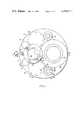
- FIG. 1is a top plan view of implantable infusion apparatus embodying the principles of this invention and for practicing our method;
- FIG. 2is a sectional view along lines 2--2 of FIG. 1;
- FIG. 3is an enlarged sectional view along lines 3--3 of FIG. 2;
- FIG. 4Ais a similar view along lines 4A--4A of FIG. 1;
- FIG. 4Bis a similar view along lines 4B--4B of FIG. 1;
- FIG. 4Cis a similar view along lines 4C--4C of FIG. 1;
- FIG. 5is a diagrammatic view of the infusion apparatus of this invention.
- FIGS. 6A to 6Bare graphical illustrations of valve functions and flow rates of the FIG. 5 system
- FIG. 7is a schematic illustration of a modification of the FIG. 5 system.
- FIGS. 8A through 8Care graphical illustrations of flows in the FIG. 7 apparatus.
- the infusion apparatuscomprises a generally cylindrical housing 10 made of stainless steel, titanium or other strong corrosion resistant material.
- housing 10is on the order of three inches in diameter and one inch thick.
- housing 10is composed of a pair of upper and lower cup-like sections 10a and 10b which are secured together at their rims along with the edge 12a of a circular plate 12 which divides the housing into upper and lower compartments 14 and 16. That securement may be accomplished by a circumferential weld bead 18 or by other appropriate means.
- Plate 12forms a header for a bellows capsule 22 situated in compartment 16.
- One end 22a of the bellows capsuleis welded, brazed or otherwise secured to an edge margin of plate 12 just inside the weld bead 18.
- the opposite end 22b of the capsuleis closed.
- a circular central portion 12b of plate 12 inside the bellows capsuleis dished downwardly as viewed in FIG. 2. Engagement of that portion by the bellows end wall 22b prevents excessive compression of the bellows which event might cause undue stresses on the capsule.
- the dished portionalso maximizes the volume of housing compartment 14 and minimizes the residual or dead volume of the basal reservoir.
- Capsule 22is preferably a titanium welded metal bellows and its diameter is slightly smaller than housing 10 to maximize the capsule volume, e.g., 20 ml.
- the space inside the capsuleconstitutes the main reservoir for infusate at the basal concentration, e.g., 20-30 units per milliliter.
- a fluid outlet from the confined volume of the capsuleis provided at 24 in plate 12.
- Subassembly 28comprises an inverted cup 32 nested in the top of housing section 10a near one side thereof. Cup 32 is provided with a circular cover 34 whose edge is welded or otherwise secured to the rim of cup 32 to form a closed compartment 36 inside the cup.
- One and 38a of a second or bolus bellows capsule 38is secured to the inside of cover 34 near the outer edge thereof, the opposite capsule end 38b being closed.
- the central portion 34a of cover 34 inside the bellows capsule 38is dished for the same reasons discussed above in connection with cover 12.
- Capsule 38is, like capsule 22, a welded metal bellows, its extended volume being about one-fifth that of capsule 22, e.g. 4 ml.
- the space inside bellows capsule 38is the secondary infusate reservoir that contains the higher concentration infusate suitable for the bolus doses, e.g. 300-400 units per milliliter.
- a fluid outlet from the capsuleis provided through an opening 42 in cover 34.
- the space outside capsule 38, but inside chamber 36contains a two-phase fluid of the type described above in connection with capsule 22. At physiological temperatures that fluid exerts pressure on capsule 38, causing the capsule to collapse and expel its contents through opening 42.
- Subassembly 46Nested between cover portions 12b and 34a is a third or auxiliary reservoir subassembly indicated generally at 46.
- Subassembly 46includes an inverted cup 50 having a generally circular cover 48 welded to its rim.
- a third bellows capsule 52has one end 52a welded or otherwise secured to the inside of cover 50 near its edge and the opposite end 52b of the capsule is closed.
- the space inside capsule 52constitutes an auxiliary reservoir or accumulator for bolus infusate.
- the space outside capsule 52, yet inside cup 50contains a compressible fluid, a spring or a two-phase fluid which, at body temperatures, exerts less pressure on capsule 52 than the similar fluid exerts on capsule 38 but enough to expel infusate into the patient's arterial or venous system.
- Capsule 52is also a welded metal bellows and is quite small, being on the order of one-hundredth the volume of capsule 38, e.g. 0.04 ml.
- a fluid inlet to the capsuleis provided through an opening 56 in a central recessed portion 50a of cover 50 and an outlet from capsule 52 is provided by a passage 58 in the cover near its edge.
- compartment 14also includes a wafer-like filter unit 59 which receives infusate from bellows capsule 22 through a length of tubing 60 connected between capsule outlet 24 and filter inlet 61. All of the connecting tubing in the apparatus is quite small, e.g. 0.012 inch I.D.
- Filter unit 59comprises upper and lower circular shells 59a and 59b whose rims interfit so that the two sections form a cylindrical housing. Inside the housing are a pair of identical circular wafer-like filter support or retainer elements 62a and 62b made of porous stainless steel, titanium or other similar porous material. Sandwiched between the filter retainers is the filter element (not shown) providing filtration to about 0.22 microns. An O-ring 63 encircles element 62b inside shell 59b to provide a seal between the shell and the filter. The two shells are held together by C-lips 64 distributed around the edges of the filter unit 59.
- the filter inlet 61is formed in the bottom wall of shell 59b and the filter outlet 65 is formed in the top wall of shell 59a.
- the infusate from capsule outlet 24flows to a flow restricter 72 in housing compartment 14.
- the restricter 72is simply a length of capillary tubing 74 coiled inside a ring 76, the space in and around the coil being filled with potting material 78.
- the restrictorcan be of many configurations. See U.S. Pat. No. 3,951,147.
- the outlet 65 of filter 62is connected by tubing 84 to one end of the coiled capillary tubing 74, the opposite end of the tubing being connected by tubing 86 to a mixing chamber indicated generally at 88 formed in a radially recessed portion 90 in the side wall of housing section 10a as best seen in FIG. 2. From the mixing chamber 88, the infusate is conducted by way of tubing 92 to an infusion site in the patient, the opposite end of tubing 92 being fitted with an appropriate catheter.
- a second filter 102is positioned in housing compartment 14 to receive the bolus infusate from bellows capsule 38. Fluid communication is achieved between those two components by a length of tubing 104 (FIG. 2) extending between the capsule outlet 42 and the filter inlet. Filter 102 is identical to filter 62 illustrated in FIG. 4B and accordingly it will not be detailed. From filter 102, the bolus infusate proceeds to a second flow restricter 106 which is, except for its length perhaps, identical to the restricter 72 illustrated in FIG. 4C. Therefore, we will not describe the restricter 106 in detail. The fluid output from restricter 106 is fed to the auxiliary bellows capsule 52 or accumulator by means of tubing 108 extending between the flow restricter and the capsule inlet 56. Infusate flow out of that capsule is through tubing 110 connected between capsule outlet 58 and a valve assembly mounted in housing compartment 14 and indicated generally at 112.
- the bolus infusateis conducted by tubing 114 containing a flow restrictor 116 to mixing chamber 88.
- Restriction 116is present simply for flow definition and smoothening purposes and that function may very well be provided by the regular tubing segment between the valve assembly and the chamber.
- valve assembly 112comprises a generally cylindrical cup 118 which fits in an opening 120 formed in the top of housing section 10a so that a small length of the cup projects out through the top of the opening.
- a circumferential welded seam 122connects the cup to housing section 10a.
- a circular disk 124Positioned at the bottom of cup 118 is a circular disk 124 which supports a relatively heavy coil spring 126, the disk being grooved to center the spring.
- a second, lighter coil spring 128 positioned inside spring 126also rests on disk 124 being centered there by a raised boss 132 on that disk.
- a circular plate 134Seated on the spring 128 inside spring 126 is a circular plate 134 having a central boss 134a projecting down into spring 128.
- Plate 134supports the upper ends of four posts 136 which extend down between springs 126 and 128 and through loose-fitting openings 138 in disk 124.
- a circular plate 142Connected to the lower ends of those posts is a circular plate 142, clearance for the plate being provided by an opening 144 in the bottom wall of cup 118.
- the valve assemblyalso includes an actuating button 146 in the form of an inverted cup which fits down snugly inside cup 118 resting on the upper end of spring 126.
- Button 146has a depending axial nose 146a which projects down into a mating opening 134b in the top of plate 134 to help center the components of the valve assembly.
- a flexible, resilient circular membrane 152is positioned at the rim of cup 118 and retained there by a circular internally threaded ring 154 which is turned down onto external threads 156 on the projecting portion of cup 118.
- Membrane 152provides a resilient impervious seal all around the button.
- the final component of the valve assemblyis a length of flexible resilient tubing 158 made of silastic or other comparable material sandwiched between disk 124 and plate 142.
- One end of the tubingcommunicates with tube 110 leading to the outlet of auxiliary bellows capsule 52.
- the other end of the tubingconnects with the tube 114 leading to the restrictor 116 and mixing chamber 88.
- the flexible tubingis recessed into a groove 124a formed in the underside of disk 124 to maintain the tubing in a centered position in the assembly.
- both springs 126 and 128are extended so that the button is in its uppermost position. In that position, the plate 134, being biased upwardly by spring 128, assumes its uppermost position thereby drawing plate 142 up along with it and squeezing the tubing 158 between plate 142 and disk 124 so that no fluid can flow through the tubing.
- the plates 134 and 142are forced downwardly so that the tubing 158 assumes its normal cylindrical shape allowing fluid to flow from bellows capsule 52 to mixing chamber 88.
- the advantage of utilizing the double spring arrangement illustrated in FIG. 2is that the force which compresses the relatively delicate flexible tubing 158 is provided by the relatively light-weight spring 128.
- the heavy spring 126determines the force required to depress button 146 sufficiently to open the valve. Desirably, the required actuating force should be relatively great so that the valve cannot be opened accidentally. In other words, a single spring could not provide both a relatively small squeezing force on tubing 158 and a relatively great return bias force on button 146.
- a self-sealing penetrable septum assembly shown generally at 162is mounted at one side of housing section 10a through which infusate at the basal concentration can be injected into the apparatus to refill bellows capsule 22.
- a similar assembly indicated generally at 164is located on the opposite side of housing section 10a.
- Both of these septum assembliesare identical so that only the former one is illustrated in detail in FIG. 4A. It comprises a cup 168 positioned in an opening 170 in the top wall of housing section 10a, the rim of teh cup projecting above the housing wall. A circumferential weld 171 permanently connects the wall of the cup to the edge of opening 170 inside the housing section. Cup 168 has a relatively large diameter upper section 168a and a smaller diameter lower section 168b defining a cylindrical space 172. An opening 174 is provided in the bottom wall of cup 168 in which is connected one end of a tube 176 which leads to the bellows capsule 22.
- a wafer-like penetrable septum or plugmade of rubber or other comparable material.
- the septumis held in place by a ring 180 which is externally threaded so that it can be screwed or pressed down onto the projecting portion of cup 168 which carries internal threads 182.
- a needle stop 183such as a wafer of teflon or other plastic material to receive the needle point during refill. Holes through the wafer allow the infusate to exit the chamber.
- a hypodermic needleis pierced through septum 178 so that is projects into chamber 172. Thence the infusate is injected into the chamber 172 whereupon it flows through tube 176 under the injection pressure to the bellows capsule 22. The incoming infusate extends the capsule and thereby compresses the two-phase fluid in housing compartment 16, thereby recharging the power cell that drives that capsule all as described in the aforesaid patents.
- capsule 52is refilled and its power cell recharged by infusate injection through septum 164.
- FIG. 5 of the drawingsis a diagrammatic view showing more clearly the flow paths between the various infusion apparatus components and to the waveforms in FIGS. 6A to 6C depicting the basal, bolus and integrated unit flow rates for the apparatus in operation.
- the basal reservoir 22has been completely filled and charged by injection of infusate in the basal concentration through septum 162.
- the bolus reservoir 38has been filled and charged by injection of the bolus infusate through septum 164.
- Basal infusateflows through filter 59 and flow restricter 72 to the mixing chamber 88 at a very slow rate, e.g., on the order of 0.6 ml/day, the specific rate depending upon the particular patient's basal insulin requirement. From chamber 88 the infusate proceeds through tubing 92 to the catheter and into the patient's physiological system.
- the infusate from the bolus reservoir 38proceeds through filter 102 and flow restricter 106 at an even slower rate of about 0.16 ml/day to accumulator 52.
- the incoming infusategradually extends the accumulator in opposition to the gas pressure or spring bias thereon until the accumulator is fully extended in which position it may hold, for example, 0.044 ml, constituting, say, one bolus infusion dose for a particular patient.
- Valve 112being normally closed, prevents infusate flow from accumulator 52 to the mixing chamber 88. Accordingly as seen from FIG. 6A, the patient receives a continuous infusate dose at the basal concentration at a rate of about 0.6 ml/day.
- the patientconsumes a meal at time T m .
- the patient's blood sugar levelnormally tends to rise relatively dramatically so that the basal insulin dosage does not suffice to offset the increased glucose level in patient's bloodstream.
- the patientcan actuate the valve 112 by manually depressing button 146 positioned under the patient's skin.
- the opening of that valvepermits the accumulator 52 to expel its contents through the restrictor 116 to the mixing chamber 88 a relatively high rate for a very short time period, say 320 ml/day for several seconds or a few minutes.
- accumulator 52has a very small volume, it contains infusate in a high concentration presenting a large total bolus dose. Accordingly as seen from FIG. 6B, the dosage rate measured in infusate units per day is quite high, if short-lived, due to the high volumetric flow rate and the high drug concentration from the accumulator to the mixing chamber.
- the bolus infusatemixes with and supplements the basal infustate still arriving from the basal reservoir 22, with the integrated infusate dosage to the patient being reflected in FIG. 6C.
- the integrated flow rateis not simply the instantaneous sum of the basal and bolus rates illustrated in FIGS. 6A and 6B. Rather, it is a more complex function of reservoir volumes, infusate concentrations, flow path resistance, mixing chamber volume, outlet tube volume and valve-on-time.
- the segment of the FIG. 6C curve indicated at A denoting the basal infusate flow rateis, of course, a function of the basal infusate concentration and voumetric flow rate through restrictor 72 to the mixing chamber.
- a bolus dose of high concentration infusateis issued to chamber 88 where it mixes with the basal infusate present there so that a short-lived "slug" of high concentration infusate at a high flow rate is dispensed to the patient as indicated by the curve segment C in FIG. 6C.
- the dose rate of infusatedrops to a level that is still higher than the original basal rate, as indicated by the curve segment D in FIG. 6C (since the high volumetric flow rate has ceased, the dose is defined by the flow rate of restrictor 72 and the concentration in the bolus reservoir).
- the dose rateremains at that level for a relatively long period indicated which time duration depends upon the volumetric flow rate through restrictor 72 and the volume of liquid in the mixing chamber and the outlet catheter.
- the unit ratefalls back to the original basal rate as the low concentration infusate at the flow rate for restrictor 72 mixes with and reduces the concentration of liquid in the mixing chamber as shown by curve segment E in FIG. 6C.
- the infusion rate peak (because of mixing of basal and bolus concentrations) indicated in FIG. 6Ctrails off more or less in an expotential fashion as indicated by the dotted line curve W 1 in that figure.
- the transition from the higher rate at curve segment D to the basal rate at segment Efalls off expotentially as shown by the dotted line curved W 2 in FIG. 6C.
- the time constants of the curve segments W 1 and W 2can be varied by varying the volume of chamber 88 the differences in drug concentrations and the flow rate through restrictor tube 72.
- the present apparatusas soon as the valve 112 controlling the bolus flow is opened when the need arises, high concentration infusate is immediately dispensed to the patient with minimal system inertia.
- the desired dosage transition from the bolus back down to the basal ratemay vary from patient to patient. For example, in one patient it may take a fairly long time for his glucose level to drop back to its ambient level after a meal due to physiological factors, while another patient may reach his nominal glucose level more quickly.
- the present apparatusis advantaged, then, in that its integrated infusate output to each patient can be tailored to suit his particular needs by proper selection of basal and bolus infusate concentrations mixing chmaber and catheter volume, restrictor flow rates and valve actuation time. Accordingly, the apparatus allows great flexibility in prescibing infusate to a patient over a prolonged period.
- the apparatusdispenses high concentration infusate for the bolus doses, the low concentration basal supply is not depleted for that purpose as in prior apparatus of this type.
- the bolus reservoircan have a relativly small volume and the valve-open time of the valve 112 can be quite short thereby conserving energy in the event that an electrically operated valve is employed. Accordingly, the apparatus can remain implanted in the body for a prolonged period, e.g. a year or more, without having to be recharged, with only relatively infrequent, e.g. monthyl, infusate refills being required during that period.
- the present apparatusalso protects the patient from inadvertant bolus infusate overdoses in the event that valve 112 is opened repeatedly or is held in the open position. More particularly, each time valve 112 is opened by the patient, the maximum volume of bolus infusate that is dispensed to the patient is the contents of accumulator 52 representing, say, one bolus infusate dose. This is because the flow restrictor 106 between filter 102 and the accumulator is such that the accumulator is refilled from reservoir 38 at an extremely slow rate, e.g. 0.16 ml/day. Accordingly, even if the valve 112 remains open for a long time, e.g., an hour, the patient still receives not much more than one-quarter of the bolus dose of infusate.
- an accumulator located between an upstream very low flow rate restrictor from the bolus reservoir and a downstream valveconstitutes a significant safety feature in apparatus such as this where the patient himself administers the bolus infusate doses. It should be understood, however, that even if the accumulator is not utilized, the present apparatus has the same advantages in terms of infusate dosage flexibility, reliability and power conservation described above.
- FIG. 7shows such an apparatus employing a single reservoir 270 connected by way of a flow restrictor 272 to a T fitting 274.
- a second flow path leading from reservoir 270communicates with the fitting by way of a valve 276 and flow restrictor 278.
- the T fittingis, in turn, connected by way of a tube 280 to a catheter at the infusion site.
- an accumulator restrictorsuch as accumulator 52 with a restricted inlet can be provided upstream of valve 276 as in the case in the apparatus illustrated in FIG. 5.
- the restrictor 272provides a relatively slow basal flow rate to chamber 274 as indicated by the waveform in FIG. 8A.
- the restrictor 278provides for a much greater or substantially unrestricted bolus flow from reservoir 270 to the fitting 274 when the valve 276 is opened at meal time as indicated by the curve in FIG. 8B.
- the integrated unit dose rate that is dispensed at the infusion siteis represented by the curve in FIG. 8C.
- the present implantable infusion apparatusdispenses infusate in one or more concentrations of one or more types at rates to suit the particular patient's requirements.
- the infusate flow rate characteristicscan be tailored with precision simply by modifying the flow rates and volumes of the apparatus components, particularly the mixing chamber and the apparatus outlet tube. Since the apparatus can dispense infusate in different concentrations, it can supply the patient's basal and bolus requirements in a minimum overall package so that the presence of the apparatus in the body is not unduly discomforting in terms of the space that it occupies in the body or in terms of the frequency with which it must be refilled or recharged.
Landscapes
- Health & Medical Sciences (AREA)
- Vascular Medicine (AREA)
- Engineering & Computer Science (AREA)
- Anesthesiology (AREA)
- Biomedical Technology (AREA)
- Heart & Thoracic Surgery (AREA)
- Hematology (AREA)
- Life Sciences & Earth Sciences (AREA)
- Animal Behavior & Ethology (AREA)
- General Health & Medical Sciences (AREA)
- Public Health (AREA)
- Veterinary Medicine (AREA)
- Infusion, Injection, And Reservoir Apparatuses (AREA)
Abstract
Description
Claims (12)
Priority Applications (1)
| Application Number | Priority Date | Filing Date | Title |
|---|---|---|---|
| US05/076,169US4258711A (en) | 1979-02-05 | 1979-09-17 | Infusion apparatus and method |
Applications Claiming Priority (2)
| Application Number | Priority Date | Filing Date | Title |
|---|---|---|---|
| US06/009,756US4193397A (en) | 1977-12-01 | 1979-02-05 | Infusion apparatus and method |
| US05/076,169US4258711A (en) | 1979-02-05 | 1979-09-17 | Infusion apparatus and method |
Related Parent Applications (1)
| Application Number | Title | Priority Date | Filing Date |
|---|---|---|---|
| US06/009,756DivisionUS4193397A (en) | 1977-12-01 | 1979-02-05 | Infusion apparatus and method |
Publications (1)
| Publication Number | Publication Date |
|---|---|
| US4258711Atrue US4258711A (en) | 1981-03-31 |
Family
ID=26679849
Family Applications (1)
| Application Number | Title | Priority Date | Filing Date |
|---|---|---|---|
| US05/076,169Expired - LifetimeUS4258711A (en) | 1979-02-05 | 1979-09-17 | Infusion apparatus and method |
Country Status (1)
| Country | Link |
|---|---|
| US (1) | US4258711A (en) |
Cited By (87)
| Publication number | Priority date | Publication date | Assignee | Title |
|---|---|---|---|---|
| DE3321472A1 (en)* | 1982-06-14 | 1983-12-15 | Infusaid Corp., Norwood, Mass. | IMPLANTABLE INFUSION DEVICE |
| WO1984001718A1 (en)* | 1982-11-04 | 1984-05-10 | Univ Johns Hopkins | Fluid handling system for medication infusion system |
| US4557726A (en)* | 1982-12-27 | 1985-12-10 | Consolidated Controls Corporation | Precision medication dispensing system and method |
| FR2569987A1 (en)* | 1984-09-07 | 1986-03-14 | Sigma Medical France Sa | Self-contained implantable device and its use for administering active substances in the human body |
| EP0202696A1 (en)* | 1985-05-21 | 1986-11-26 | Applied Precision Limited | Manually activated implantable device for dispensing therapeutic substances |
| US4634424A (en)* | 1984-04-23 | 1987-01-06 | Windsor Medical, Inc. | Multiple re-entry implantable septum and method of using same |
| US4634427A (en)* | 1984-09-04 | 1987-01-06 | American Hospital Supply Company | Implantable demand medication delivery assembly |
| US4699615A (en)* | 1984-06-21 | 1987-10-13 | Fischell David R | Finger actuated medication infusion system |
| WO1987006473A1 (en)* | 1986-04-24 | 1987-11-05 | Centre National De La Recherche Scientifique (Cnrs | Rechargeable implantable device for dosed and repeated self-injection of medicament |
| US4813951A (en)* | 1987-05-20 | 1989-03-21 | Joel Wall | Self-actuated implantable pump |
| US4846806A (en)* | 1987-10-06 | 1989-07-11 | 501 Regents Of University Of Minnesota | Implantable intravascular access system |
| US4871351A (en)* | 1984-09-28 | 1989-10-03 | Vladimir Feingold | Implantable medication infusion system |
| WO1989010157A1 (en)* | 1988-04-21 | 1989-11-02 | Therex Corporation | Dual access infusion and monitoring system |
| USD305262S (en) | 1987-08-03 | 1989-12-26 | Playschool Baby, Inc. | Nasal aspirator |
| US4898585A (en)* | 1988-05-18 | 1990-02-06 | Baxter Healthcare Corporation | Implantable patient-activated fluid delivery device with bolus injection port |
| US4898583A (en)* | 1988-05-18 | 1990-02-06 | Baxter Healthcare Corporation | Implantable patient-activated fluid delivery device and outlet valve therefor |
| US4898584A (en)* | 1988-05-18 | 1990-02-06 | Baxter Healthcare Corporation | Implantable patient-activated fluid delivery device |
| EP0344895A3 (en)* | 1988-04-13 | 1990-02-07 | Shiley Infusaid Inc. | Constant pressure variable flow implantable pump |
| US4978338A (en)* | 1988-04-21 | 1990-12-18 | Therex Corp. | Implantable infusion apparatus |
| US5067943A (en)* | 1989-09-26 | 1991-11-26 | Infusaid, Inc. | Pressure regulator for implantable pump |
| DE4038050A1 (en)* | 1990-11-29 | 1992-06-04 | Anschuetz & Co Gmbh | VALVE FOR AN IMPLANTABLE INFUSION PUMP |
| US5185003A (en)* | 1989-04-11 | 1993-02-09 | B. Braun Melsungen Ag | Port for injecting medicaments |
| WO1993025262A1 (en) | 1992-06-16 | 1993-12-23 | Infusaid, Inc. | Dual access catheter for implantable pump system |
| WO1994026348A1 (en)* | 1993-04-13 | 1994-11-24 | Science Incorporated | Fluid delivery apparatus |
| US5389078A (en)* | 1993-10-06 | 1995-02-14 | Sims Deltec, Inc. | Programmable infusion pump for administering medication to patients |
| US5411480A (en)* | 1989-06-16 | 1995-05-02 | Science Incorporated | Fluid delivery apparatus |
| US5492533A (en)* | 1989-06-16 | 1996-02-20 | Science, Inc. | Fluid delivery apparatus |
| US5718682A (en)* | 1996-06-28 | 1998-02-17 | United States Surgical Corporation | Access port device and method of manufacture |
| US5776103A (en)* | 1995-10-11 | 1998-07-07 | Science Incorporated | Fluid delivery device with bolus injection site |
| US5785681A (en)* | 1997-02-25 | 1998-07-28 | Minimed Inc. | Flow rate controller for a medication infusion pump |
| US5810015A (en)* | 1995-09-01 | 1998-09-22 | Strato/Infusaid, Inc. | Power supply for implantable device |
| US5957891A (en)* | 1995-10-11 | 1999-09-28 | Science Incorporated | Fluid delivery device with fill adapter |
| US5957895A (en)* | 1998-02-20 | 1999-09-28 | Becton Dickinson And Company | Low-profile automatic injection device with self-emptying reservoir |
| EP0988838A3 (en)* | 1995-03-23 | 2000-05-24 | Advanced Animal Technology Limited | Substance delivery device |
| FR2792842A1 (en)* | 1999-04-30 | 2000-11-03 | Medtronic Inc | Implantable medication pump for controlling cardiac fibrillation, etc. has principal reservoir for medication and assembly delivering dose as bolus from reservoir |
| US6283943B1 (en)* | 1999-02-19 | 2001-09-04 | Minimed Inc. | Negative pressure pump |
| AU745389B2 (en)* | 1995-03-23 | 2002-03-21 | Advanced Animal Technology Limited | Substance delivery device including a delivery apparatus |
| WO2002017989A3 (en)* | 2000-08-30 | 2002-05-16 | Medtronic Inc | System and method for attaching upper and lower outer cases in an implantable drug pump |
| US6471675B1 (en) | 1999-04-30 | 2002-10-29 | Medtronic, Inc. | Passive flow control devices for implantable pumps |
| US20030176797A1 (en)* | 2002-03-12 | 2003-09-18 | Fernando Anzellini | Thrombust; implantable delivery system sensible to self diagnosis of acute myocardial infarction for thrombolysis in the first minutes of chest pain |
| US20030208184A1 (en)* | 2000-01-11 | 2003-11-06 | Paul Burke | Implantable, refillable infusion device and spetum replacement kit |
| US20030216684A1 (en)* | 2002-03-26 | 2003-11-20 | Fentress James K. | Multi-stage fluid delivery device and method |
| US6730060B1 (en)* | 1998-05-29 | 2004-05-04 | Fresenius Medical Care Deutschland Gmbh | Implantable device for administering a treatment solution and operating device for a syringe for filling the device |
| US6740075B2 (en)* | 2000-01-21 | 2004-05-25 | Medtronic Minimed, Inc. | Ambulatory medical apparatus with hand held communication device |
| US20040138612A1 (en)* | 2002-07-22 | 2004-07-15 | Shermer Charles D. | Patch-like infusion device |
| US20040162518A1 (en)* | 2000-08-18 | 2004-08-19 | Connelly Robert I. | Constant rate fluid delivery device with selectable flow rate and titratable bolus button |
| US20050065472A1 (en)* | 2003-07-22 | 2005-03-24 | Cindrich Chris N. | Patch-like infusion device |
| US20050070875A1 (en)* | 2003-09-30 | 2005-03-31 | Codman & Shurtleff, Inc. | Two-compartment reduced volume infusion pump |
| US20050119618A1 (en)* | 2003-04-23 | 2005-06-02 | Gonnelli Robert R. | Hydraulically actuated pump for long duration medicament administration |
| US6962579B2 (en) | 1995-03-23 | 2005-11-08 | Advanced Animal Technology Limited | Substance delivery device |
| US20060030838A1 (en)* | 2004-07-02 | 2006-02-09 | Gonnelli Robert R | Methods and devices for delivering GLP-1 and uses thereof |
| US20060034943A1 (en)* | 2003-10-31 | 2006-02-16 | Technology Innovations Llc | Process for treating a biological organism |
| US20060271022A1 (en)* | 2005-05-25 | 2006-11-30 | Palion Medical Corporation | Multi-reservoir implantable pump with variable flow rate capabilities |
| US20070078380A1 (en)* | 2002-08-12 | 2007-04-05 | Marc Yap | System and method for tension-activated fluid control |
| US20080306454A1 (en)* | 2007-06-06 | 2008-12-11 | Sikora Christopher F | Apparatus And Method For Sterilization Of An Intravenous Catheter |
| US20090131859A1 (en)* | 2007-11-16 | 2009-05-21 | Baxter International Inc. | Flow pulsatility dampening devices for closed-loop controlled infusion systems |
| US20090227989A1 (en)* | 2008-03-05 | 2009-09-10 | Burke Paul F | Multiple reservoir implantable drug infusion device and method |
| US20090240232A1 (en)* | 2006-03-30 | 2009-09-24 | Vakerutas,Llc | Multi-cartridge fluid delivery device |
| EP2138198A1 (en) | 2008-06-27 | 2009-12-30 | Codman Neuro Sciences Sarl | Fluidic capillary chip for regulating drug flow rates of infusion pumps |
| US20100018923A1 (en)* | 2008-07-25 | 2010-01-28 | Baxter International Inc. | Dialysis system with flow regulation device |
| US20100094203A1 (en)* | 2008-10-15 | 2010-04-15 | Kriesel Marshall S | Special purpose fluid dispenser |
| US20100094218A1 (en)* | 2008-10-15 | 2010-04-15 | Kriesel Marshall S | Special purpose fluid dispenser with pre-filled reservoir |
| US7708730B2 (en) | 2006-01-30 | 2010-05-04 | Palyon Medical (Bvi) Limited | Template system for multi-reservoir implantable pump |
| US20100209267A1 (en)* | 2009-02-18 | 2010-08-19 | Davis David L | Infusion pump with integrated permanent magnet |
| US20100211002A1 (en)* | 2009-02-18 | 2010-08-19 | Davis David L | Electromagnetic infusion pump with integral flow monitor |
| US20100209268A1 (en)* | 2009-02-18 | 2010-08-19 | Davis David L | Low cost disposable infusion pump |
| US20110125137A1 (en)* | 2009-11-25 | 2011-05-26 | Medtronic, Inc. | Implantable infusion device |
| US8366667B2 (en) | 2010-02-11 | 2013-02-05 | Baxter International Inc. | Flow pulsatility dampening devices |
| US8591456B2 (en) | 2011-12-28 | 2013-11-26 | Palyon Medical (Bvi) Limited | Multiple reservoir programmable pump |
| US8945071B2 (en) | 2010-09-02 | 2015-02-03 | Becton, Dickinson And Company | Self-injection device having needle cover with activation preventer |
| US8961469B2 (en) | 2009-12-16 | 2015-02-24 | Becton, Dickinson And Company | Self-injection device |
| EP2532376A3 (en)* | 2006-02-09 | 2016-03-09 | DEKA Products Limited Partnership | Pumping fluid delivery systems using force application assembly |
| US9295773B2 (en) | 2010-11-09 | 2016-03-29 | Frank Prosl | Hemodialysis access system |
| US9526830B2 (en) | 2007-12-31 | 2016-12-27 | Deka Products Limited Partnership | Wearable pump assembly |
| US9555187B2 (en) | 2009-12-16 | 2017-01-31 | Becton, Dickinson And Company | Self-injection device |
| US9579461B2 (en) | 2009-12-16 | 2017-02-28 | Becton, Dickinson And Company | Self-injection device |
| US9717850B2 (en) | 2009-12-16 | 2017-08-01 | Becton, Dickinson And Company | Self-injection device |
| US9833562B2 (en) | 2009-12-16 | 2017-12-05 | Becton, Dickinson And Company | Self-injection device |
| US10195340B2 (en) | 2009-12-16 | 2019-02-05 | Becton, Dickinson And Company | Self-injection device |
| US10272195B2 (en) | 2007-02-09 | 2019-04-30 | Deka Products Limited Partnership | Infusion pump assembly |
| US11185624B2 (en)* | 2016-06-03 | 2021-11-30 | Kci Licensing, Inc. | Negative-pressure therapy with disposable instillation pump chamber |
| US11404776B2 (en) | 2007-12-31 | 2022-08-02 | Deka Products Limited Partnership | Split ring resonator antenna adapted for use in wirelessly controlled medical device |
| US11497686B2 (en) | 2007-12-31 | 2022-11-15 | Deka Products Limited Partnership | Apparatus, system and method for fluid delivery |
| US11534542B2 (en) | 2007-12-31 | 2022-12-27 | Deka Products Limited Partnership | Apparatus, system and method for fluid delivery |
| US11642283B2 (en) | 2007-12-31 | 2023-05-09 | Deka Products Limited Partnership | Method for fluid delivery |
| US11723841B2 (en) | 2007-12-31 | 2023-08-15 | Deka Products Limited Partnership | Apparatus, system and method for fluid delivery |
| US12415031B2 (en) | 2007-12-31 | 2025-09-16 | Deka Products Limited Partnership | Wearable pump assembly |
Citations (8)
| Publication number | Priority date | Publication date | Assignee | Title |
|---|---|---|---|---|
| US3840009A (en)* | 1971-12-27 | 1974-10-08 | Alza Corp | Self-powered vapor pressure delivery device |
| US3923060A (en)* | 1974-04-23 | 1975-12-02 | Jr Everett H Ellinwood | Apparatus and method for implanted self-powered medication dispensing having timing and evaluator means |
| US4013074A (en)* | 1974-06-21 | 1977-03-22 | Siposs George G | Implantable medication-dispensing device |
| US4056095A (en)* | 1975-04-04 | 1977-11-01 | Agence Nationale De Valorisation De La Recherche (Anvar) | Control device for medical and surgical uses |
| US4077405A (en)* | 1975-03-26 | 1978-03-07 | Siemens Aktiengesellschaft | Apparatus for infusing liquids into human or animal bodies |
| US4137913A (en)* | 1975-02-28 | 1979-02-06 | Ivac Corporation | Fluid flow control system |
| US4146029A (en)* | 1974-04-23 | 1979-03-27 | Ellinwood Jr Everett H | Self-powered implanted programmable medication system and method |
| US4193397A (en)* | 1977-12-01 | 1980-03-18 | Metal Bellows Corporation | Infusion apparatus and method |
- 1979
- 1979-09-17USUS05/076,169patent/US4258711A/ennot_activeExpired - Lifetime
Patent Citations (8)
| Publication number | Priority date | Publication date | Assignee | Title |
|---|---|---|---|---|
| US3840009A (en)* | 1971-12-27 | 1974-10-08 | Alza Corp | Self-powered vapor pressure delivery device |
| US3923060A (en)* | 1974-04-23 | 1975-12-02 | Jr Everett H Ellinwood | Apparatus and method for implanted self-powered medication dispensing having timing and evaluator means |
| US4146029A (en)* | 1974-04-23 | 1979-03-27 | Ellinwood Jr Everett H | Self-powered implanted programmable medication system and method |
| US4013074A (en)* | 1974-06-21 | 1977-03-22 | Siposs George G | Implantable medication-dispensing device |
| US4137913A (en)* | 1975-02-28 | 1979-02-06 | Ivac Corporation | Fluid flow control system |
| US4077405A (en)* | 1975-03-26 | 1978-03-07 | Siemens Aktiengesellschaft | Apparatus for infusing liquids into human or animal bodies |
| US4056095A (en)* | 1975-04-04 | 1977-11-01 | Agence Nationale De Valorisation De La Recherche (Anvar) | Control device for medical and surgical uses |
| US4193397A (en)* | 1977-12-01 | 1980-03-18 | Metal Bellows Corporation | Infusion apparatus and method |
Cited By (189)
| Publication number | Priority date | Publication date | Assignee | Title |
|---|---|---|---|---|
| US4525165A (en)* | 1979-04-27 | 1985-06-25 | The Johns Hopkins University | Fluid handling system for medication infusion system |
| GB2121690A (en)* | 1982-06-14 | 1984-01-04 | Infusaid Corp | Implantable infusate pump |
| DE3321472A1 (en)* | 1982-06-14 | 1983-12-15 | Infusaid Corp., Norwood, Mass. | IMPLANTABLE INFUSION DEVICE |
| WO1984001718A1 (en)* | 1982-11-04 | 1984-05-10 | Univ Johns Hopkins | Fluid handling system for medication infusion system |
| EP0124555A4 (en)* | 1982-11-04 | 1986-11-26 | Univ Johns Hopkins | FLUID REGULATION SYSTEM FOR A DRUG INFUSION APPARATUS. |
| US4557726A (en)* | 1982-12-27 | 1985-12-10 | Consolidated Controls Corporation | Precision medication dispensing system and method |
| US4634424A (en)* | 1984-04-23 | 1987-01-06 | Windsor Medical, Inc. | Multiple re-entry implantable septum and method of using same |
| US4699615A (en)* | 1984-06-21 | 1987-10-13 | Fischell David R | Finger actuated medication infusion system |
| US4634427A (en)* | 1984-09-04 | 1987-01-06 | American Hospital Supply Company | Implantable demand medication delivery assembly |
| FR2569987A1 (en)* | 1984-09-07 | 1986-03-14 | Sigma Medical France Sa | Self-contained implantable device and its use for administering active substances in the human body |
| US4871351A (en)* | 1984-09-28 | 1989-10-03 | Vladimir Feingold | Implantable medication infusion system |
| FR2582222A1 (en)* | 1985-05-21 | 1986-11-28 | Applied Precision Ltd | IMPLANTABLE MANUAL ACTION DEVICE FOR THE SEQUENTIAL DELIVERY OF DOSES OF A SUBSTANCE, ESPECIALLY THERAPEUTIC |
| EP0202696A1 (en)* | 1985-05-21 | 1986-11-26 | Applied Precision Limited | Manually activated implantable device for dispensing therapeutic substances |
| WO1987006473A1 (en)* | 1986-04-24 | 1987-11-05 | Centre National De La Recherche Scientifique (Cnrs | Rechargeable implantable device for dosed and repeated self-injection of medicament |
| US4857059A (en)* | 1986-04-24 | 1989-08-15 | Centre National De La Recherche Scientifique | Rechargeable implantable device for dosed and repeated self-injection of medicament |
| US4813951A (en)* | 1987-05-20 | 1989-03-21 | Joel Wall | Self-actuated implantable pump |
| USD305262S (en) | 1987-08-03 | 1989-12-26 | Playschool Baby, Inc. | Nasal aspirator |
| US4846806A (en)* | 1987-10-06 | 1989-07-11 | 501 Regents Of University Of Minnesota | Implantable intravascular access system |
| EP0344895A3 (en)* | 1988-04-13 | 1990-02-07 | Shiley Infusaid Inc. | Constant pressure variable flow implantable pump |
| AU618999B2 (en)* | 1988-04-13 | 1992-01-16 | Programmable Pump Technologies, Inc. | Constant pressure variable flow pump |
| US4931050A (en)* | 1988-04-13 | 1990-06-05 | Shiley Infusaid Inc. | Constant pressure variable flow pump |
| AU623653B2 (en)* | 1988-04-21 | 1992-05-21 | Therex Corporation | Dual access infusion and monitoring system |
| EP0612535B2 (en)† | 1988-04-21 | 2008-05-14 | CODMAN & SHURTLEFF, INC. | Implantable infusion apparatus |
| WO1989010157A1 (en)* | 1988-04-21 | 1989-11-02 | Therex Corporation | Dual access infusion and monitoring system |
| US4955861A (en)* | 1988-04-21 | 1990-09-11 | Therex Corp. | Dual access infusion and monitoring system |
| US4978338A (en)* | 1988-04-21 | 1990-12-18 | Therex Corp. | Implantable infusion apparatus |
| US4898585A (en)* | 1988-05-18 | 1990-02-06 | Baxter Healthcare Corporation | Implantable patient-activated fluid delivery device with bolus injection port |
| US4898583A (en)* | 1988-05-18 | 1990-02-06 | Baxter Healthcare Corporation | Implantable patient-activated fluid delivery device and outlet valve therefor |
| US4898584A (en)* | 1988-05-18 | 1990-02-06 | Baxter Healthcare Corporation | Implantable patient-activated fluid delivery device |
| US5185003A (en)* | 1989-04-11 | 1993-02-09 | B. Braun Melsungen Ag | Port for injecting medicaments |
| US5411480A (en)* | 1989-06-16 | 1995-05-02 | Science Incorporated | Fluid delivery apparatus |
| US5492533A (en)* | 1989-06-16 | 1996-02-20 | Science, Inc. | Fluid delivery apparatus |
| US5067943A (en)* | 1989-09-26 | 1991-11-26 | Infusaid, Inc. | Pressure regulator for implantable pump |
| US5088983A (en)* | 1989-09-26 | 1992-02-18 | Infusaid, Inc. | Pressure regulator for implantable pump |
| DE4038050A1 (en)* | 1990-11-29 | 1992-06-04 | Anschuetz & Co Gmbh | VALVE FOR AN IMPLANTABLE INFUSION PUMP |
| WO1993025262A1 (en) | 1992-06-16 | 1993-12-23 | Infusaid, Inc. | Dual access catheter for implantable pump system |
| WO1994026348A1 (en)* | 1993-04-13 | 1994-11-24 | Science Incorporated | Fluid delivery apparatus |
| US5389078A (en)* | 1993-10-06 | 1995-02-14 | Sims Deltec, Inc. | Programmable infusion pump for administering medication to patients |
| EP0988838A3 (en)* | 1995-03-23 | 2000-05-24 | Advanced Animal Technology Limited | Substance delivery device |
| US6500168B1 (en) | 1995-03-23 | 2002-12-31 | Advanced Animal Technology Ltd. | Substance delivery device |
| US6436069B1 (en) | 1995-03-23 | 2002-08-20 | Advanced Animal Technology Limited | Substance delivery device |
| US6962579B2 (en) | 1995-03-23 | 2005-11-08 | Advanced Animal Technology Limited | Substance delivery device |
| AU745389B2 (en)* | 1995-03-23 | 2002-03-21 | Advanced Animal Technology Limited | Substance delivery device including a delivery apparatus |
| US5810015A (en)* | 1995-09-01 | 1998-09-22 | Strato/Infusaid, Inc. | Power supply for implantable device |
| US5776103A (en)* | 1995-10-11 | 1998-07-07 | Science Incorporated | Fluid delivery device with bolus injection site |
| US5957891A (en)* | 1995-10-11 | 1999-09-28 | Science Incorporated | Fluid delivery device with fill adapter |
| US5718682A (en)* | 1996-06-28 | 1998-02-17 | United States Surgical Corporation | Access port device and method of manufacture |
| US5785681A (en)* | 1997-02-25 | 1998-07-28 | Minimed Inc. | Flow rate controller for a medication infusion pump |
| US5957895A (en)* | 1998-02-20 | 1999-09-28 | Becton Dickinson And Company | Low-profile automatic injection device with self-emptying reservoir |
| US6730060B1 (en)* | 1998-05-29 | 2004-05-04 | Fresenius Medical Care Deutschland Gmbh | Implantable device for administering a treatment solution and operating device for a syringe for filling the device |
| US6283943B1 (en)* | 1999-02-19 | 2001-09-04 | Minimed Inc. | Negative pressure pump |
| US6635049B1 (en) | 1999-04-30 | 2003-10-21 | Medtronic, Inc. | Drug bolus delivery system |
| US6471675B1 (en) | 1999-04-30 | 2002-10-29 | Medtronic, Inc. | Passive flow control devices for implantable pumps |
| FR2792842A1 (en)* | 1999-04-30 | 2000-11-03 | Medtronic Inc | Implantable medication pump for controlling cardiac fibrillation, etc. has principal reservoir for medication and assembly delivering dose as bolus from reservoir |
| US6979315B2 (en) | 1999-04-30 | 2005-12-27 | Medtronic, Inc. | Passive flow control devices for implantable pumps |
| US7108686B2 (en) | 2000-01-11 | 2006-09-19 | Bard Access Systems, Inc. | Implantable, refillable infusion device and septum replacement kit |
| US20030208184A1 (en)* | 2000-01-11 | 2003-11-06 | Paul Burke | Implantable, refillable infusion device and spetum replacement kit |
| US6764472B1 (en) | 2000-01-11 | 2004-07-20 | Bard Access Systems, Inc. | Implantable refillable infusion device |
| US20040249363A1 (en)* | 2000-01-11 | 2004-12-09 | Bard Access Systems, Inc. | Implantable, refillable infusion device and septum replacement kit |
| US6740075B2 (en)* | 2000-01-21 | 2004-05-25 | Medtronic Minimed, Inc. | Ambulatory medical apparatus with hand held communication device |
| US9533096B2 (en) | 2000-01-21 | 2017-01-03 | Medtronic Minimed, Inc. | Microprocessor controlled ambulatory medical apparatus with hand held communication device |
| US20110270045A1 (en)* | 2000-01-21 | 2011-11-03 | Medtronic Minimed, Inc. | Microprocessor controlled ambulatory medical apparatus with hand held communication device |
| US20040193090A1 (en)* | 2000-01-21 | 2004-09-30 | Medtronic Minimed, Inc. | Ambulatory medical apparatus with handheld communication device |
| US7831310B2 (en) | 2000-01-21 | 2010-11-09 | Medtronic Minimed, Inc. | Microprocessor controlled ambulatory medical apparatus with hand held communication device |
| US7678071B2 (en) | 2000-01-21 | 2010-03-16 | Medtronic Minimed, Inc. | Microprocessor controlled ambulatory medical apparatus with hand held communication device |
| US20050010269A1 (en)* | 2000-01-21 | 2005-01-13 | Medical Research Group, Inc. | Microprocessor controlled ambulatory medical apparatus with hand held communication device |
| US6974437B2 (en) | 2000-01-21 | 2005-12-13 | Medtronic Minimed, Inc. | Microprocessor controlled ambulatory medical apparatus with hand held communication device |
| US8568356B2 (en) | 2000-01-21 | 2013-10-29 | Medtronic Minimed, Inc. | Ambulatory medical apparatus with hand held communication device |
| US9937290B2 (en) | 2000-08-18 | 2018-04-10 | Becton, Dickinson And Company | Constant rate fluid delivery device with selectable flow rate and titratable bolus button |
| US8771227B2 (en)* | 2000-08-18 | 2014-07-08 | Becton, Dickinson And Company | Constant rate fluid delivery device with selectable flow rate and titratable bolus button |
| US20040162518A1 (en)* | 2000-08-18 | 2004-08-19 | Connelly Robert I. | Constant rate fluid delivery device with selectable flow rate and titratable bolus button |
| US6719739B2 (en) | 2000-08-30 | 2004-04-13 | Medtronic, Inc. | System and method for attaching upper and lower outer cases in an implantable drug pump |
| WO2002017989A3 (en)* | 2000-08-30 | 2002-05-16 | Medtronic Inc | System and method for attaching upper and lower outer cases in an implantable drug pump |
| US20030176797A1 (en)* | 2002-03-12 | 2003-09-18 | Fernando Anzellini | Thrombust; implantable delivery system sensible to self diagnosis of acute myocardial infarction for thrombolysis in the first minutes of chest pain |
| US20030216684A1 (en)* | 2002-03-26 | 2003-11-20 | Fentress James K. | Multi-stage fluid delivery device and method |
| EP3351277A1 (en)* | 2002-03-26 | 2018-07-25 | Becton, Dickinson and Company | Multi-stage fluid delivery device and method |
| US7214221B2 (en) | 2002-03-26 | 2007-05-08 | Becton, Dickinson And Company | Multi-stage fluid delivery device and method |
| US20070156086A1 (en)* | 2002-03-26 | 2007-07-05 | Fentress James K | Multi-stage fluid delivery device and method |
| US7678079B2 (en) | 2002-07-22 | 2010-03-16 | Becton, Dickinson And Company | Patch-like infusion device |
| US20040138612A1 (en)* | 2002-07-22 | 2004-07-15 | Shermer Charles D. | Patch-like infusion device |
| US7250037B2 (en) | 2002-07-22 | 2007-07-31 | Becton, Dickinson And Company | Patch-like infusion device |
| US20070203454A1 (en)* | 2002-07-22 | 2007-08-30 | Shermer Charles D | Patch-Like Infusion Device |
| US20070078380A1 (en)* | 2002-08-12 | 2007-04-05 | Marc Yap | System and method for tension-activated fluid control |
| US20090182265A1 (en)* | 2002-08-12 | 2009-07-16 | Lma North America, Inc | Medication infusion system and method |
| US7527608B2 (en) | 2002-08-12 | 2009-05-05 | Lma North America, Inc. | Medication infusion and aspiration system and method |
| US7520871B2 (en) | 2002-08-12 | 2009-04-21 | Lma North America, Inc | System and method for tension-activated fluid control |
| US11642456B2 (en) | 2003-04-23 | 2023-05-09 | Mannkind Corporation | Hydraulically actuated pump for fluid administration |
| US8070726B2 (en) | 2003-04-23 | 2011-12-06 | Valeritas, Inc. | Hydraulically actuated pump for long duration medicament administration |
| US9072828B2 (en) | 2003-04-23 | 2015-07-07 | Valeritas, Inc. | Hydraulically actuated pump for long duration medicament administration |
| US7530968B2 (en) | 2003-04-23 | 2009-05-12 | Valeritas, Inc. | Hydraulically actuated pump for long duration medicament administration |
| US9125983B2 (en) | 2003-04-23 | 2015-09-08 | Valeritas, Inc. | Hydraulically actuated pump for fluid administration |
| US20100217191A1 (en)* | 2003-04-23 | 2010-08-26 | Valeritas, Inc. | Hydraulically actuated pump for fluid administration |
| US10525194B2 (en) | 2003-04-23 | 2020-01-07 | Valeritas, Inc. | Hydraulically actuated pump for fluid administration |
| US20050119618A1 (en)* | 2003-04-23 | 2005-06-02 | Gonnelli Robert R. | Hydraulically actuated pump for long duration medicament administration |
| US9511187B2 (en) | 2003-04-23 | 2016-12-06 | Valeritas, Inc. | Hydraulically actuated pump for fluid administration |
| US10589023B2 (en) | 2003-07-22 | 2020-03-17 | Becton, Dickinson And Company | Patch-like infusion device |
| US9597450B2 (en) | 2003-07-22 | 2017-03-21 | Becton, Dickinson And Company | Patch-like infusion device |
| US9364606B2 (en) | 2003-07-22 | 2016-06-14 | Becton, Dickinson And Company | Patch-like infusion device |
| US20050065472A1 (en)* | 2003-07-22 | 2005-03-24 | Cindrich Chris N. | Patch-like infusion device |
| US9999724B2 (en) | 2003-07-22 | 2018-06-19 | Becton, Dickinson And Company | Patch-like infusion device |
| US8512287B2 (en) | 2003-07-22 | 2013-08-20 | Becton, Dickinson And Company | Patch-like infusion device |
| US20050065466A1 (en)* | 2003-08-12 | 2005-03-24 | Becton, Dickinson And Company | Patch-like infusion device |
| US8444604B2 (en) | 2003-08-12 | 2013-05-21 | Becton, Dickinson And Company | Patch-like infusion device |
| US20080215015A1 (en)* | 2003-08-12 | 2008-09-04 | Chris Cindrich | Patch-Like Infusion Device |
| US7857131B2 (en) | 2003-08-12 | 2010-12-28 | Becton, Dickinson And Company | Patch-like infusion device |
| US20050070875A1 (en)* | 2003-09-30 | 2005-03-31 | Codman & Shurtleff, Inc. | Two-compartment reduced volume infusion pump |
| US7896865B2 (en) | 2003-09-30 | 2011-03-01 | Codman & Shurtleff, Inc. | Two-compartment reduced volume infusion pump |
| US20060034943A1 (en)* | 2003-10-31 | 2006-02-16 | Technology Innovations Llc | Process for treating a biological organism |
| US20060030838A1 (en)* | 2004-07-02 | 2006-02-09 | Gonnelli Robert R | Methods and devices for delivering GLP-1 and uses thereof |
| US9089636B2 (en) | 2004-07-02 | 2015-07-28 | Valeritas, Inc. | Methods and devices for delivering GLP-1 and uses thereof |
| US20090182307A1 (en)* | 2004-07-30 | 2009-07-16 | Lma North America, Inc. | System and Method for Tension-Activated Fluid Control |
| US20060271022A1 (en)* | 2005-05-25 | 2006-11-30 | Palion Medical Corporation | Multi-reservoir implantable pump with variable flow rate capabilities |
| US8034030B2 (en) | 2005-05-25 | 2011-10-11 | Palyon Medical (Bvi) Limited | Multi-reservoir implantable pump with variable flow rate capabilities |
| US8034029B2 (en) | 2005-05-25 | 2011-10-11 | Palyon Medical (Bvi) Limited | Multi-reservoir implantable pump with patient controlled actuation |
| WO2006127841A3 (en)* | 2005-05-25 | 2007-05-03 | Palyon Medical Corp | Multi-reservoir implantable pump with variable flow rate capabilities |
| US20060271021A1 (en)* | 2005-05-25 | 2006-11-30 | Palion Medical Corporation | Multi-reservoir implantable pump with patient controlled actuation |
| US7914510B2 (en) | 2006-01-30 | 2011-03-29 | Palyon Medical (Bvi) Limited | Template system for multi-reservoir implantable pump |
| US20100160859A1 (en)* | 2006-01-30 | 2010-06-24 | Palyon Medical (Bvi) Limited | Template system for multi-reservoir implantable pump |
| US7708730B2 (en) | 2006-01-30 | 2010-05-04 | Palyon Medical (Bvi) Limited | Template system for multi-reservoir implantable pump |
| EP2532376A3 (en)* | 2006-02-09 | 2016-03-09 | DEKA Products Limited Partnership | Pumping fluid delivery systems using force application assembly |
| US10328215B2 (en) | 2006-02-09 | 2019-06-25 | Deka Products Limited Partnership | Patch-sized fluid delivery systems and methods |
| US9943652B2 (en) | 2006-02-09 | 2018-04-17 | Deka Products Limited Partnership | Adhesive and peripheral systems and methods for medical devices |
| US10383999B2 (en) | 2006-02-09 | 2019-08-20 | Deka Products Limited Partnership | Fluid delivery systems and methods |
| US12036387B2 (en) | 2006-02-09 | 2024-07-16 | Deka Products Limited Partnership | Device to determine volume of fluid dispensed |
| US10975854B2 (en) | 2006-02-09 | 2021-04-13 | Deka Products Limited Partnership | Pumping fluid delivery systems and methods using force application assembly |
| US20090240232A1 (en)* | 2006-03-30 | 2009-09-24 | Vakerutas,Llc | Multi-cartridge fluid delivery device |
| US20110137287A1 (en)* | 2006-03-30 | 2011-06-09 | Valeritas, Inc. | Multi-cartridge fluid delivery device |
| US9687599B2 (en) | 2006-03-30 | 2017-06-27 | Valeritas, Inc. | Multi-cartridge fluid delivery device |
| US12246159B2 (en) | 2006-03-30 | 2025-03-11 | Mannkind Corporation | Multi-cartridge fluid delivery device |
| US7914499B2 (en) | 2006-03-30 | 2011-03-29 | Valeritas, Inc. | Multi-cartridge fluid delivery device |
| US8361053B2 (en) | 2006-03-30 | 2013-01-29 | Valeritas, Inc. | Multi-cartridge fluid delivery device |
| US8821443B2 (en) | 2006-03-30 | 2014-09-02 | Valeritas, Inc. | Multi-cartridge fluid delivery device |
| US10493199B2 (en) | 2006-03-30 | 2019-12-03 | Valeritas, Inc. | Multi-cartridge fluid delivery device |
| US10272195B2 (en) | 2007-02-09 | 2019-04-30 | Deka Products Limited Partnership | Infusion pump assembly |
| US20080306454A1 (en)* | 2007-06-06 | 2008-12-11 | Sikora Christopher F | Apparatus And Method For Sterilization Of An Intravenous Catheter |
| US8449500B2 (en) | 2007-11-16 | 2013-05-28 | Baxter International Inc. | Flow pulsatility dampening devices for closed-loop controlled infusion systems |
| US20090131859A1 (en)* | 2007-11-16 | 2009-05-21 | Baxter International Inc. | Flow pulsatility dampening devices for closed-loop controlled infusion systems |
| US9526830B2 (en) | 2007-12-31 | 2016-12-27 | Deka Products Limited Partnership | Wearable pump assembly |
| US12128006B2 (en) | 2007-12-31 | 2024-10-29 | Deka Products Limited Partnership | Apparatus, system and method for fluid delivery |
| US11497686B2 (en) | 2007-12-31 | 2022-11-15 | Deka Products Limited Partnership | Apparatus, system and method for fluid delivery |
| US11404776B2 (en) | 2007-12-31 | 2022-08-02 | Deka Products Limited Partnership | Split ring resonator antenna adapted for use in wirelessly controlled medical device |
| US11642283B2 (en) | 2007-12-31 | 2023-05-09 | Deka Products Limited Partnership | Method for fluid delivery |
| US10912882B2 (en) | 2007-12-31 | 2021-02-09 | Deka Products Limited Partnership | Infusion pump assembly |
| US11701300B2 (en) | 2007-12-31 | 2023-07-18 | Deka Products Limited Partnership | Method for fluid delivery |
| US9931461B2 (en) | 2007-12-31 | 2018-04-03 | Deka Products Limited Partnership | Pump assembly with switch |
| US12415031B2 (en) | 2007-12-31 | 2025-09-16 | Deka Products Limited Partnership | Wearable pump assembly |
| US11534542B2 (en) | 2007-12-31 | 2022-12-27 | Deka Products Limited Partnership | Apparatus, system and method for fluid delivery |
| US11723841B2 (en) | 2007-12-31 | 2023-08-15 | Deka Products Limited Partnership | Apparatus, system and method for fluid delivery |
| US11894609B2 (en) | 2007-12-31 | 2024-02-06 | Deka Products Limited Partnership | Split ring resonator antenna adapted for use in wirelessly controlled medical device |
| US12121497B2 (en) | 2007-12-31 | 2024-10-22 | Deka Products Limited Partnership | Method for fluid delivery |
| US20090227989A1 (en)* | 2008-03-05 | 2009-09-10 | Burke Paul F | Multiple reservoir implantable drug infusion device and method |
| US8545477B2 (en)* | 2008-03-05 | 2013-10-01 | Flowonix Medical Incorporated | Multiple reservoir implantable drug infusion device and method |
| US8551044B2 (en)* | 2008-03-05 | 2013-10-08 | Flowonix Medical Incorporated | Multiple reservoir implantable drug infusion device and method |
| US20100089487A1 (en)* | 2008-03-05 | 2010-04-15 | Burke Paul F | Multiple reservoir implantable drug infusion device and method |
| US20090326517A1 (en)* | 2008-06-27 | 2009-12-31 | Toralf Bork | Fluidic capillary chip for regulating drug flow rates of infusion pumps |
| EP2138198A1 (en) | 2008-06-27 | 2009-12-30 | Codman Neuro Sciences Sarl | Fluidic capillary chip for regulating drug flow rates of infusion pumps |
| US10265454B2 (en) | 2008-07-25 | 2019-04-23 | Baxter International Inc. | Dialysis system with flow regulation device |
| US11439736B2 (en) | 2008-07-25 | 2022-09-13 | Baxter International Inc. | Dialysis system with online dialysis fluid generation |
| US20100018923A1 (en)* | 2008-07-25 | 2010-01-28 | Baxter International Inc. | Dialysis system with flow regulation device |
| US8100890B2 (en)* | 2008-10-15 | 2012-01-24 | Bioquiddity, Inc. | Special purpose fluid dispenser with pre-filled reservoir |
| US7896843B2 (en)* | 2008-10-15 | 2011-03-01 | Bioquiddity, Inc. | Special purpose fluid dispenser |
| US20100094218A1 (en)* | 2008-10-15 | 2010-04-15 | Kriesel Marshall S | Special purpose fluid dispenser with pre-filled reservoir |
| US20100094203A1 (en)* | 2008-10-15 | 2010-04-15 | Kriesel Marshall S | Special purpose fluid dispenser |
| US20100209268A1 (en)* | 2009-02-18 | 2010-08-19 | Davis David L | Low cost disposable infusion pump |
| US20100211002A1 (en)* | 2009-02-18 | 2010-08-19 | Davis David L | Electromagnetic infusion pump with integral flow monitor |
| US8353864B2 (en) | 2009-02-18 | 2013-01-15 | Davis David L | Low cost disposable infusion pump |
| US20100209267A1 (en)* | 2009-02-18 | 2010-08-19 | Davis David L | Infusion pump with integrated permanent magnet |
| US8197235B2 (en) | 2009-02-18 | 2012-06-12 | Davis David L | Infusion pump with integrated permanent magnet |
| US20110125137A1 (en)* | 2009-11-25 | 2011-05-26 | Medtronic, Inc. | Implantable infusion device |
| US9259530B2 (en)* | 2009-11-25 | 2016-02-16 | Medtronic, Inc. | Implantable infusion device |
| US10967123B2 (en) | 2009-12-16 | 2021-04-06 | Becton, Dickinson And Company | Self-injection device |
| US9717850B2 (en) | 2009-12-16 | 2017-08-01 | Becton, Dickinson And Company | Self-injection device |
| US9919097B2 (en) | 2009-12-16 | 2018-03-20 | Becton, Dickinson And Company | Self-injection device |
| US11007316B2 (en) | 2009-12-16 | 2021-05-18 | Becton, Dickinson And Company | Self-injection device |
| US9833562B2 (en) | 2009-12-16 | 2017-12-05 | Becton, Dickinson And Company | Self-injection device |
| US9579461B2 (en) | 2009-12-16 | 2017-02-28 | Becton, Dickinson And Company | Self-injection device |
| US10420881B2 (en) | 2009-12-16 | 2019-09-24 | Becton, Dickinson And Company | Self-injection device |
| US10357610B2 (en) | 2009-12-16 | 2019-07-23 | Becton, Dickinson And Company | Self-injection device |
| US10080846B2 (en) | 2009-12-16 | 2018-09-25 | Becton, Dickinson And Company | Self-injection device |
| US9555187B2 (en) | 2009-12-16 | 2017-01-31 | Becton, Dickinson And Company | Self-injection device |
| US10195340B2 (en) | 2009-12-16 | 2019-02-05 | Becton, Dickinson And Company | Self-injection device |
| US8961469B2 (en) | 2009-12-16 | 2015-02-24 | Becton, Dickinson And Company | Self-injection device |
| US8366667B2 (en) | 2010-02-11 | 2013-02-05 | Baxter International Inc. | Flow pulsatility dampening devices |
| US8945071B2 (en) | 2010-09-02 | 2015-02-03 | Becton, Dickinson And Company | Self-injection device having needle cover with activation preventer |
| US9675752B2 (en) | 2010-09-02 | 2017-06-13 | Becton, Dickinson And Company | Self-injection device having needle cover with activation preventer |
| US9295773B2 (en) | 2010-11-09 | 2016-03-29 | Frank Prosl | Hemodialysis access system |
| US8808231B2 (en) | 2011-12-28 | 2014-08-19 | Palyon Medical (Bvi) Limited | Multiple reservoir programmable pump |
| US8591456B2 (en) | 2011-12-28 | 2013-11-26 | Palyon Medical (Bvi) Limited | Multiple reservoir programmable pump |
| US11185624B2 (en)* | 2016-06-03 | 2021-11-30 | Kci Licensing, Inc. | Negative-pressure therapy with disposable instillation pump chamber |
Similar Documents
| Publication | Publication Date | Title |
|---|---|---|
| US4258711A (en) | Infusion apparatus and method | |
| US4193397A (en) | Infusion apparatus and method | |
| US4447224A (en) | Variable flow implantable infusion apparatus | |
| US4781688A (en) | Dispensing device for a liquid medicament | |
| EP0998317B1 (en) | Inlet port for a medication infusion pump | |
| US5053031A (en) | Pump infusion system | |
| US4360019A (en) | Implantable infusion device | |
| US8771227B2 (en) | Constant rate fluid delivery device with selectable flow rate and titratable bolus button | |
| AU628054B2 (en) | Implantable infusion apparatus | |
| US4221219A (en) | Implantable infusion apparatus and method | |
| US5957891A (en) | Fluid delivery device with fill adapter | |
| EP0819012B1 (en) | Implantable drug infusion system with safe bolus capability | |
| AU724234B2 (en) | Fluid delivery device with conformable ullage and fill assembly | |
| US4838887A (en) | Programmable valve pump | |
| US4443218A (en) | Programmable implantable infusate pump | |
| EP0039124B1 (en) | Implantable infusion apparatus | |
| JP2001515371A (en) | Drug delivery device with bolus injection site | |
| US20050267422A1 (en) | Fluid delivery apparatus | |
| WO2014159866A1 (en) | Dual rate insulin pump | |
| CA1333144C (en) | Implantable drug delivery system | |
| EP0143503B1 (en) | Implantable hand-operable dispensers for fluid medicaments |
Legal Events
| Date | Code | Title | Description |
|---|---|---|---|
| AS | Assignment | Owner name:INFUSAID CORPORATION, MASSACHUSETTS Free format text:ASSIGNMENT OF ASSIGNORS INTEREST;ASSIGNOR:METAL BELLOWS CORPORATION;REEL/FRAME:003829/0450 Effective date:19810121 Owner name:INFUSAID CORPORATION, 1075 PROVIDENCE HIGHWAY, SHA Free format text:ASSIGNMENT OF ASSIGNORS INTEREST.;ASSIGNOR:METAL BELLOWS CORPORATION;REEL/FRAME:003829/0450 Effective date:19810121 | |
| AS | Assignment | Owner name:SHILEY INFUSAID, INC., HALE & DORR, 60 STATE STREE Free format text:ASSIGNMENT OF ASSIGNORS INTEREST.;ASSIGNOR:INTERMEDICS INFUSAID, INC., A TX CORP.;REEL/FRAME:004880/0098 Effective date:19861010 Owner name:INTERMEDICS INFUSAID, INC., A CORP. OF TEXAS,MASSA Free format text:ASSIGNMENT OF ASSIGNORS INTEREST;ASSIGNOR:INFUSAID CORPORATION, BY: CLINTON T. CROLIUS, TRUSTEE OF THE INFUSAID LIQUIDATING TRUST, SUCCESSOR TO THE ASSETS OF INFUSAID CORPORATION;REEL/FRAME:004880/0090 Effective date:19861010 Owner name:SHILEY INFUSAID, INC.,MASSACHUSETTS Free format text:ASSIGNMENT OF ASSIGNORS INTEREST;ASSIGNOR:INTERMEDICS INFUSAID, INC., A TX CORP.;REEL/FRAME:004880/0098 Effective date:19861010 Owner name:INTERMEDICS INFUSAID, INC., 1400 PROVIDENCE HIGHWA Free format text:ASSIGNMENT OF ASSIGNORS INTEREST.;ASSIGNOR:INFUSAID CORPORATION, BY: CLINTON T. CROLIUS, TRUSTEE OF THE INFUSAID LIQUIDATING TRUST, SUCCESSOR TO THE ASSETS OF INFUSAID CORPORATION;REEL/FRAME:004880/0090 Effective date:19861010 |