US4254849A - Damping arrangement - Google Patents
Damping arrangementDownload PDFInfo
- Publication number
- US4254849A US4254849AUS05/970,969US97096978AUS4254849AUS 4254849 AUS4254849 AUS 4254849AUS 97096978 AUS97096978 AUS 97096978AUS 4254849 AUS4254849 AUS 4254849A
- Authority
- US
- United States
- Prior art keywords
- mass
- piston rod
- damping
- piston
- arrangement
- Prior art date
- Legal status (The legal status is an assumption and is not a legal conclusion. Google has not performed a legal analysis and makes no representation as to the accuracy of the status listed.)
- Expired - Lifetime
Links
Images
Classifications
- F—MECHANICAL ENGINEERING; LIGHTING; HEATING; WEAPONS; BLASTING
- F16—ENGINEERING ELEMENTS AND UNITS; GENERAL MEASURES FOR PRODUCING AND MAINTAINING EFFECTIVE FUNCTIONING OF MACHINES OR INSTALLATIONS; THERMAL INSULATION IN GENERAL
- F16F—SPRINGS; SHOCK-ABSORBERS; MEANS FOR DAMPING VIBRATION
- F16F9/00—Springs, vibration-dampers, shock-absorbers, or similarly-constructed movement-dampers using a fluid or the equivalent as damping medium
- F16F9/32—Details
- F16F9/50—Special means providing automatic damping adjustment, i.e. self-adjustment of damping by particular sliding movements of a valve element, other than flexions or displacement of valve discs; Special means providing self-adjustment of spring characteristics
- F16F9/504—Inertia, i.e. acceleration,-sensitive means
- D—TEXTILES; PAPER
- D06—TREATMENT OF TEXTILES OR THE LIKE; LAUNDERING; FLEXIBLE MATERIALS NOT OTHERWISE PROVIDED FOR
- D06F—LAUNDERING, DRYING, IRONING, PRESSING OR FOLDING TEXTILE ARTICLES
- D06F37/00—Details specific to washing machines covered by groups D06F21/00 - D06F25/00
- D06F37/20—Mountings, e.g. resilient mountings, for the rotary receptacle, motor, tub or casing; Preventing or damping vibrations
- F—MECHANICAL ENGINEERING; LIGHTING; HEATING; WEAPONS; BLASTING
- F16—ENGINEERING ELEMENTS AND UNITS; GENERAL MEASURES FOR PRODUCING AND MAINTAINING EFFECTIVE FUNCTIONING OF MACHINES OR INSTALLATIONS; THERMAL INSULATION IN GENERAL
- F16F—SPRINGS; SHOCK-ABSORBERS; MEANS FOR DAMPING VIBRATION
- F16F2228/00—Functional characteristics, e.g. variability, frequency-dependence
- F16F2228/08—Functional characteristics, e.g. variability, frequency-dependence pre-stressed
- Y—GENERAL TAGGING OF NEW TECHNOLOGICAL DEVELOPMENTS; GENERAL TAGGING OF CROSS-SECTIONAL TECHNOLOGIES SPANNING OVER SEVERAL SECTIONS OF THE IPC; TECHNICAL SUBJECTS COVERED BY FORMER USPC CROSS-REFERENCE ART COLLECTIONS [XRACs] AND DIGESTS
- Y10—TECHNICAL SUBJECTS COVERED BY FORMER USPC
- Y10T—TECHNICAL SUBJECTS COVERED BY FORMER US CLASSIFICATION
- Y10T137/00—Fluid handling
- Y10T137/0753—Control by change of position or inertia of system
Definitions
- This inventionrelates to the damping of vibrations in rotating machinery, and particularly to a damping arrangement the damping force of which varies in response to the frequency of vibration.
- the inventionwill be described in its application to domestic laundry machinery, but is not limited to a specific field.
- Tubs of domestic laundry machinesare rotated during machine operation and tend to vibrate because of the unevenly distributed load. It is common practice to interpose damping elements between the tub assembly and the machine frame to hold the vibration amplitudes within acceptable limits. The damping effect required at certain critical rotary speeds is very high whereas equal damping at other speeds would unnecessarily absorb driving energy.
- Known damping arrangementsemploy telescopic shock absorbers of a basically conventional type in which a cylinder is at least partly filled with liquid, and a piston axially guided in the cylinder separates two compartments of the cylinder cavity and is attached to a piston rod sealed to the cylinder for axial movement into and out of the cavity.
- One or more throttling passages in the pistonconnect the compartments, but may be by-passed by a bore in the cylinder rod which has orifices in the two compartments.
- An inert massis axially guided on the piston rod and biased toward a certain axial position by a spring.
- One of the orifices leading into the axial bore of the piston rodis at least approximately blocked and unblocked in response to the axial movement of the inert mass. It has been found that the mass, when oscillating at its maximum amplitude, may knock against other elements of the shock absorber, thereby causing noisy operation and reducing the useful life of the apparatus.
- the damping arrangement of the inventionis thus equipped with a hydraulic secondary damping device which damps axial movement of the inert mass away from the position intermediate its terminal positions toward which it is biased by the associated spring.
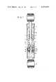
- FIG. 1shows a damping arrangement of the invention in elevational section
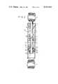
- FIG. 2illustrates a modification of the device of FIG. 1 in an analogous view.
- FIG. 1there is seen a cylinder 1 whose cavity is partly filled with hydraulic brake fluid 1a.
- a coaxial piston rod 2sealingly moves into and out of the cylinder cavity through an annular end wall 13 of the cylinder, not shown in detail.
- the other end wall of the cylinder 1 and the axial end of the piston rod 2 outside the cylinder cavitycarry respective fastening eyes 11 by means of which the illustrated damping arrangement may be mounted between the tub assembly and frame of a washing machine in a conventional manner, not shown.
- a piston 5is axially secured on the inner end of the piston rod 2 between a clamping nut 19 and a cup-shaped receptacle 9 which itself is held in position on the piston rod 2 by a spring clip 18.
- the piston 5axially separates two compartments of the cylinder cavity which may be connected by two sets 6a, 6b of axial throttling bores in the piston 5.
- the bores 6aof which only one is seen in the drawing, are normally closed toward the end wall 13 by an annular spring plate 6c clamped between the receptacle 9 and the piston 5 and permanently open in the opposite direction.
- the corresponding bores 6bare permanently open toward the end wall 13 and normally closed in the opposite direction by a spring plate 6d clamped between the piston 5 and the nut 19.
- An axial bore 3 in the piston rod 2has an orifice permanently open toward the cylinder compartment, which appears below the piston 5 in the view of FIG. 1, and two radial orifices 4 directed toward the cylinder compartment above the piston 5, but almost entirely blocked in the illustrated condition by the reduced lower end 12 of a heavy-walled control sleeve 7 freely slidable on the piston rod 2.
- the sleeve 7is normally biased toward the illustrated position by a helical wire spring 8 one end of which is secured in a circumferential groove of the sleeve portion 12, whereas its other end is received in a circumferential groove 10 of the receptacle 9.
- the cup-shaped receptacle 9is axially open toward the sleeve 7 and dimensioned to receive therein the reduced lower end 12 of the sleeve with a clearance gap sufficient to permit sharply throttled escape of the liquid otherwise trapped in the receptacle 9 during inward movement of the sleeve end 12.
- the inert mass of the sleeve 7 and the resilient force of the spring 8are selected in such a manner that the natural frequency of the oscillating system constituted thereby is different from the frequency of the particularly heavy vibrations induced in the tub assembly of the washing machine when the tub is turned during washing at a certain critical range of rotary speeds. Under these conditions, the sleeve 7 does not move significantly from the illustrated position, and the maximum damping effect of the apparatus is achieved as the liquid 1a must pass through the narrow bores 6a, 6b.
- the sleeve 7may not come within range of the end wall 13, and no secondary damping device may be needed to brake the approach of the sleeve 7 to the end wall 13. If this is necessary, the otherwise practically unchanged apparatus of FIG. 1 may be modified in the manner illustrated in FIG. 2.
- the annular end wall 13' on the cylinder 1 of the modified damping arrangementcarries a stationary, coaxial, tubular plunger 14.
- the clearance gap 15' between the piston rod 2 and the main body of the sleeve 7', not otherwise different from the sleeve 7,is widened sufficiently to provide a receptacle in which the plunger 14 is received as the sleeve 7' approaches its terminal position adjacent the end wall 13', whereby the viscous resistance of the liquid 1a to displacement from the receptacle 15' by the plunger 14 brakes the sleeve 7' to a standstill before it can strike the end wall 13'.
- the only other illustrated feature in which the embodiment of FIG. 2 differs from the device of FIG. 1consists of an internal, axial face 16 of the receptacle 9' which tapers conically inward of the receptacle.
- the effective flow section of the throttling gap between the cylindrical outer face of the sleeve end and the conical inner face of the receptacle 9'decreases gradually for increasing the damping effect.
- this effectmay be further modified by giving a conical shape also to the sleeve end 12, and the receptacle 15 and plunger 14 may be modified in an analogous manner.
- Other variations and permutationswill readily suggest themselves on the basis of the above teachings.
- the illustrated positions of the male and female damping elements on the inert mass of the sleeve 7 and on the piston or cylindermay be interchanged.
- two receptaclesmay be installed on the sleeve 7' for cooperation with plungers on the end wall 13', as actually shown, and on the piston 5 respectively without basically affecting the mode of operation.
Landscapes
- Engineering & Computer Science (AREA)
- General Engineering & Computer Science (AREA)
- Mechanical Engineering (AREA)
- Textile Engineering (AREA)
- Fluid-Damping Devices (AREA)
- Main Body Construction Of Washing Machines And Laundry Dryers (AREA)
Abstract
Description
This invention relates to the damping of vibrations in rotating machinery, and particularly to a damping arrangement the damping force of which varies in response to the frequency of vibration.
The invention will be described in its application to domestic laundry machinery, but is not limited to a specific field. Tubs of domestic laundry machines are rotated during machine operation and tend to vibrate because of the unevenly distributed load. It is common practice to interpose damping elements between the tub assembly and the machine frame to hold the vibration amplitudes within acceptable limits. The damping effect required at certain critical rotary speeds is very high whereas equal damping at other speeds would unnecessarily absorb driving energy.
Known damping arrangements employ telescopic shock absorbers of a basically conventional type in which a cylinder is at least partly filled with liquid, and a piston axially guided in the cylinder separates two compartments of the cylinder cavity and is attached to a piston rod sealed to the cylinder for axial movement into and out of the cavity. One or more throttling passages in the piston connect the compartments, but may be by-passed by a bore in the cylinder rod which has orifices in the two compartments. An inert mass is axially guided on the piston rod and biased toward a certain axial position by a spring. One of the orifices leading into the axial bore of the piston rod is at least approximately blocked and unblocked in response to the axial movement of the inert mass. It has been found that the mass, when oscillating at its maximum amplitude, may knock against other elements of the shock absorber, thereby causing noisy operation and reducing the useful life of the apparatus.
It is a primary object of this invention to provide a frequency responsive damping arrangement which avoids the aforedescribed shortcomings of known arrangements by damping the velocity of the oscillating inert mass, particularly at maximum amplitude.
The damping arrangement of the invention is thus equipped with a hydraulic secondary damping device which damps axial movement of the inert mass away from the position intermediate its terminal positions toward which it is biased by the associated spring.
Other features, additional objects, and many of the attendant advantages of this invention will readily be appreciated as the same becomes better understood by reference to the following detailed description of preferred embodiments when considered in connection with the appended drawing in which:
FIG. 1 shows a damping arrangement of the invention in elevational section; and
FIG. 2 illustrates a modification of the device of FIG. 1 in an analogous view.
Referring initially to FIG. 1, there is seen a cylinder 1 whose cavity is partly filled withhydraulic brake fluid 1a. Acoaxial piston rod 2 sealingly moves into and out of the cylinder cavity through anannular end wall 13 of the cylinder, not shown in detail. The other end wall of the cylinder 1 and the axial end of thepiston rod 2 outside the cylinder cavity carry respective fasteningeyes 11 by means of which the illustrated damping arrangement may be mounted between the tub assembly and frame of a washing machine in a conventional manner, not shown.
Apiston 5 is axially secured on the inner end of thepiston rod 2 between aclamping nut 19 and a cup-shaped receptacle 9 which itself is held in position on thepiston rod 2 by aspring clip 18. Thepiston 5 axially separates two compartments of the cylinder cavity which may be connected by twosets 6a, 6b of axial throttling bores in thepiston 5. The bores 6a, of which only one is seen in the drawing, are normally closed toward theend wall 13 by anannular spring plate 6c clamped between thereceptacle 9 and thepiston 5 and permanently open in the opposite direction. Thecorresponding bores 6b are permanently open toward theend wall 13 and normally closed in the opposite direction by aspring plate 6d clamped between thepiston 5 and thenut 19.
Anaxial bore 3 in thepiston rod 2 has an orifice permanently open toward the cylinder compartment, which appears below thepiston 5 in the view of FIG. 1, and tworadial orifices 4 directed toward the cylinder compartment above thepiston 5, but almost entirely blocked in the illustrated condition by the reducedlower end 12 of a heavy-walled control sleeve 7 freely slidable on thepiston rod 2. Thesleeve 7 is normally biased toward the illustrated position by ahelical wire spring 8 one end of which is secured in a circumferential groove of thesleeve portion 12, whereas its other end is received in acircumferential groove 10 of thereceptacle 9.
When thesleeve 7 moves axially upward from the illustrated position, itslower end 12 clears theorifices 4, and liquid can pass freely between the two cylinder compartments through thebore 3 whose flow section is greater than that available frombores 6a, 6b. If thesleeve 7 shifts downward, theorifices 4 communicate with an enlarged,annular gap 15 between the main body of thesleeve 7 and thepiston rod 2 until thesleeve 7 again fully clears theorifices 4. Thespring plates piston rod 2 moves inward of the cylinder 1, and to open thebores 6b during outward piston rod movement. The leakage path available between thesleeve end 12 and thepiston rod 2 in the illustrated sleeve position has a flow section much smaller than that of either set ofbores 6a, 6b.
The cup-shaped receptacle 9 is axially open toward thesleeve 7 and dimensioned to receive therein the reducedlower end 12 of the sleeve with a clearance gap sufficient to permit sharply throttled escape of the liquid otherwise trapped in thereceptacle 9 during inward movement of thesleeve end 12.
The inert mass of thesleeve 7 and the resilient force of thespring 8 are selected in such a manner that the natural frequency of the oscillating system constituted thereby is different from the frequency of the particularly heavy vibrations induced in the tub assembly of the washing machine when the tub is turned during washing at a certain critical range of rotary speeds. Under these conditions, thesleeve 7 does not move significantly from the illustrated position, and the maximum damping effect of the apparatus is achieved as theliquid 1a must pass through thenarrow bores 6a, 6b.
When the tub is accelerated from washing speed to spinning or centrifuging speed, it exceeds the critical range of speeds, and the resulting vibratory frequency is close enough to the natural frequency of thesleeve 7 andspring 8 to cause oscillation of the sleeve about the position shown in FIG. 1. When the oscillations reach sufficient amplitude, thelower sleeve end 12 dips into thereceptacle 9, and its kinetic energy is partly converted into heat in theliquid 1a as the liquid is squeezed out of the receptacle through the narrow gap between concentric cylindrical faces of thereceptacle 9 and thesleeve end 12.
Depending on the manner in which the damping arrangement is mounted between the washing machine frame and the tub assembly, thesleeve 7 may not come within range of theend wall 13, and no secondary damping device may be needed to brake the approach of thesleeve 7 to theend wall 13. If this is necessary, the otherwise practically unchanged apparatus of FIG. 1 may be modified in the manner illustrated in FIG. 2.
The annular end wall 13' on the cylinder 1 of the modified damping arrangement carries a stationary, coaxial,tubular plunger 14. The clearance gap 15' between thepiston rod 2 and the main body of the sleeve 7', not otherwise different from thesleeve 7, is widened sufficiently to provide a receptacle in which theplunger 14 is received as the sleeve 7' approaches its terminal position adjacent the end wall 13', whereby the viscous resistance of theliquid 1a to displacement from the receptacle 15' by theplunger 14 brakes the sleeve 7' to a standstill before it can strike the end wall 13'.
The only other illustrated feature in which the embodiment of FIG. 2 differs from the device of FIG. 1 consists of an internal,axial face 16 of the receptacle 9' which tapers conically inward of the receptacle. As thesleeve end 12 enters the receptacle 9', the effective flow section of the throttling gap between the cylindrical outer face of the sleeve end and the conical inner face of the receptacle 9' decreases gradually for increasing the damping effect.
As not specifically illustrated, but obvious from the showing of FIG. 2, this effect may be further modified by giving a conical shape also to thesleeve end 12, and thereceptacle 15 andplunger 14 may be modified in an analogous manner. Other variations and permutations will readily suggest themselves on the basis of the above teachings. The illustrated positions of the male and female damping elements on the inert mass of thesleeve 7 and on the piston or cylinder may be interchanged. In a device according to FIG. 2, two receptacles may be installed on the sleeve 7' for cooperation with plungers on the end wall 13', as actually shown, and on thepiston 5 respectively without basically affecting the mode of operation.
It should be understood, therefore, that the foregoing disclosure relates only to currently preferred embodiments, and that it is intended to cover all changes and modifications of the examples of the invention herein chosen for the purpose of the disclosure which do not constitute departures from the spirit and scope of the invention set forth in the appended claims.
Claims (10)
1. A damping arrangement comprising:
(a) a cylinder member having an axis and bounding a cavity therein;
(b) a piston rod sealingly engaging said cylinder member for axial movement inward and outward of said cavity;
(c) a liquid in said cavity;
(d) a piston member mounted on said piston rod in said cavity and axially defining two compartments of said cavity,
(1) said piston member being formed with at least one throttling passage for restricted flow of said liquid between said compartments,
(2) said piston rod being formed with a bore having respective orifices in said compartments for by-passing said piston member,
(e) an inert mass mounted on said piston rod for axial movement in one of said compartments between two axially terminal positions;
(f) blocking means movable in said cavity toward and away from a blocking position in which said blocking means impedes flow of said liquid through one of said orifices, said blocking means constituting a portion of said inert mass and said blocking means being moved toward and away from said blocking position in response to said axial movement of said mass;
(g) a spring interposed between said mass and said piston rod for biasing said mass toward a pre-determined axial position spacedly intermediate said terminal positions, ; and
(h) hydraulic damping means for damping axial movement of said mass in a direction away from said intermediate position and toward both of said terminal positions to prevent contact with said piston and the end wall of said cylinder member in said compartment, said damping means comprising first damping elements on said inert mass and a second damping element on each of said piston and end wall in said one compartment, one of said first and second elements bounding a receptacle open axially toward the other element, the other element being dimensioned to be received in said receptacle during axial movement of said mass.
2. An arragement as set forth in claim 1, wherein the effective flow section of said at least one throttling passage is greater than the effective flow section of said bore when said blocking means is in said blocking position, and smaller than the effective flow section of said bore when said blocking means is away from said blocking position.
3. An arrangement as set forth in claim 1, wherein said hydraulic damping means damp movement of said mass only when said mass closely approaches a terminal position thereof.
4. An arrangement as set forth in claim 1, wherein said first damping elements constitute an integral portion of said mass.
5. An arrangement as set forth in claim 1, wherein said one element is mounted on said piston rod.
6. An arrangement as set forth in claim 1, wherein said one element is fixedly connected to said mass, said other element being mounted on said cylinder member.
7. An arrangement as set forth in claim 1, wherein said receptacle and the other element received therein bound an axially open throttling gap for escape of said liquid from said receptacle during movement of said other element inward of said receptacle.
8. An arrangement as set forth in claim 7, wherein the effective flow section of said gap decreases during said inward movement of said other element.
9. An arrangement as set forth in claim 1, wherein said spring has two axial ends respectively fastened to said mass and to said second damping element.
10. An arrangement as set forth in claim 1, wherein one of said second damping elements is axially secured on said piston rod and abuttingly engages said piston member.
Applications Claiming Priority (2)
| Application Number | Priority Date | Filing Date | Title |
|---|---|---|---|
| DE2758083 | 1977-12-24 | ||
| DE19772758083DE2758083A1 (en) | 1977-12-24 | 1977-12-24 | FREQUENCY-DEPENDENT VIBRATION DAMPER |
Publications (1)
| Publication Number | Publication Date |
|---|---|
| US4254849Atrue US4254849A (en) | 1981-03-10 |
Family
ID=6027332
Family Applications (1)
| Application Number | Title | Priority Date | Filing Date |
|---|---|---|---|
| US05/970,969Expired - LifetimeUS4254849A (en) | 1977-12-24 | 1978-12-19 | Damping arrangement |
Country Status (7)
| Country | Link |
|---|---|
| US (1) | US4254849A (en) |
| JP (2) | JPS5493773A (en) |
| DE (1) | DE2758083A1 (en) |
| FR (1) | FR2412757A1 (en) |
| GB (1) | GB2011021B (en) |
| IT (2) | IT7854005V0 (en) |
| SE (1) | SE7813202L (en) |
Cited By (36)
| Publication number | Priority date | Publication date | Assignee | Title |
|---|---|---|---|---|
| JPH01178244U (en)* | 1988-01-29 | 1989-12-20 | ||
| EP0487311A1 (en)* | 1990-11-19 | 1992-05-27 | Kabushiki Kaisha Showa Seisakusho | Vibration damper assembly |
| US5127498A (en)* | 1990-01-16 | 1992-07-07 | Massachusetts Institute Of Technology | Impedance matches mass damper |
| US5332068A (en)* | 1990-04-03 | 1994-07-26 | Richardson Technologies, Ltd. | Self contained automatic terrain condition adjusting shock absorber |
| WO1996027091A1 (en)* | 1995-03-01 | 1996-09-06 | Ricor Racing & Development, L.P. | Flow sensitive, acceleration sensitive shock absorber |
| US5667041A (en)* | 1995-11-03 | 1997-09-16 | General Motors Corporation | Suspension strut with hydraulic stop |
| WO1998014718A1 (en)* | 1996-10-04 | 1998-04-09 | Ricor Racing & Development, L.P. | ACCELERATION SENSITIVE FLOW SENSITIVE McPHERSON STRUT |
| WO1998034044A3 (en)* | 1997-02-04 | 1998-11-19 | Ricor Racing And Dev L P | Acceleration sensitive shock absorber |
| US5884733A (en)* | 1998-01-27 | 1999-03-23 | Rockshox, Inc. | Temperature compensating system for fluid-damped suspension systems |
| US6102170A (en)* | 1998-05-07 | 2000-08-15 | Tenneco Automotive Inc. | Passive anti-roll system |
| US6105987A (en)* | 1997-12-17 | 2000-08-22 | Rockshox, Inc. | Valve mechanism for damping system |
| US6253889B1 (en)* | 1997-02-04 | 2001-07-03 | Ricor Racing And Development, Lp | Acceleration sensitive shock absorber |
| WO2003021130A1 (en)* | 2001-08-30 | 2003-03-13 | Fox Factory, Inc. | Inertia valve shock absorber |
| US6581948B2 (en) | 2001-08-30 | 2003-06-24 | Fox Factory, Inc. | Inertia valve shock absorber |
| US6644446B2 (en)* | 2000-11-09 | 2003-11-11 | Daido Metal Company Ltd. | Hydraulic shock-absorber |
| US20030213662A1 (en)* | 2001-08-30 | 2003-11-20 | Fox Robert C. | Inertia valve shock absorber |
| US20040222056A1 (en)* | 2001-08-30 | 2004-11-11 | Fox Robert C. | Inertia valve shock absorber |
| US20050087953A1 (en)* | 2001-07-02 | 2005-04-28 | Becker William M. | Bicycle fork cartridge assembly |
| EP1564434A1 (en)* | 2004-02-13 | 2005-08-17 | Brandt Industries SAS | Damping device for a washing machine |
| US20060071380A1 (en)* | 2002-11-05 | 2006-04-06 | Toyo Tire & Rubber Co., Ltd. | Vibration isolator |
| EP1712812A1 (en)* | 2001-08-30 | 2006-10-18 | Fox Factory, Inc. | Inertia valve shock absorber |
| US20070119670A1 (en)* | 2001-08-30 | 2007-05-31 | Fox Factory, Inc. | Inertia valve fluid damper with reservoir positioned blowoff valve |
| US20070221458A1 (en)* | 2006-03-11 | 2007-09-27 | Zf Friedrichshafen Ag | Vibration damper |
| CN100404907C (en)* | 2004-09-15 | 2008-07-23 | 舒适宝控股有限公司 | damper |
| RU2361134C2 (en)* | 2007-07-12 | 2009-07-10 | Борис Батразович Карсанов | Vehicle hydro pneumatic shock absorber |
| US7641028B2 (en) | 2002-06-25 | 2010-01-05 | Fox Factory, Inc. | Integrated and self-contained suspension assembly having an on-the-fly adjustable air spring |
| CN103104650A (en)* | 2011-11-10 | 2013-05-15 | 株式会社万都 | Shock absorber |
| US8607942B2 (en) | 2006-04-02 | 2013-12-17 | Fox Factory, Inc. | Suspension damper having inertia valve and user adjustable pressure-relief |
| US9415653B2 (en) | 2002-06-25 | 2016-08-16 | Fox Factory, Inc. | Gas spring with travel control |
| US9802670B2 (en) | 2002-06-25 | 2017-10-31 | Fox Factory, Inc. | Gas spring curve control in an adjustable volume gas pressurized device |
| US10018239B2 (en) | 2002-09-05 | 2018-07-10 | Fox Factory, Inc. | Travel control for a gas spring and gas spring having very short travel modes |
| US20180371673A1 (en)* | 2017-06-22 | 2018-12-27 | Haier Us Appliance Solutions, Inc. | Washing machine appliance and methods of operation |
| WO2019019862A1 (en)* | 2017-07-28 | 2019-01-31 | 青岛海尔滚筒洗衣机有限公司 | Shock absorber and laundry treatment device comprising shock absorber |
| US10941828B2 (en) | 2002-06-25 | 2021-03-09 | Fox Factory, Inc. | Gas spring with travel control |
| WO2021046113A1 (en) | 2019-09-06 | 2021-03-11 | Pratt & Miller Engineering and Fabrication, Inc. | Compact, injury mitigating, recoverable, isolated floor system related applications |
| US20230219519A1 (en)* | 2020-05-25 | 2023-07-13 | Stabilus Gmbh | Self-regulating damper unit |
Families Citing this family (15)
| Publication number | Priority date | Publication date | Assignee | Title |
|---|---|---|---|---|
| DE3120016A1 (en)* | 1981-05-20 | 1982-12-09 | Stabilus Gmbh, 5400 Koblenz | SHOCK ABSORBER WITH SPEED-RELATED DAMPER DEVICE |
| FR2583125B1 (en)* | 1985-06-10 | 1987-12-24 | Applic Mach Motrices | SHOCK ABSORBER FOR HEAVY VEHICLE SUSPENSION ELEMENT |
| JPH0425551Y2 (en)* | 1987-07-31 | 1992-06-18 | ||
| DE4029596A1 (en)* | 1990-09-19 | 1992-03-26 | Teves Gmbh Alfred | Vibration damper for vehicles - includes by=pass pipe and axially displaceable inertia bodies |
| DE4417961A1 (en)* | 1994-05-21 | 1995-11-23 | Schaeffler Waelzlager Kg | Arrangement for damping pressure pulses |
| DE4419870A1 (en)* | 1994-06-07 | 1995-12-14 | Suspa Compart Ag | Friction dampers, in particular for washing machines with a spin cycle |
| FR2739667B1 (en)* | 1995-10-04 | 1997-11-28 | Donerre Amortisseur Soc | IMPROVEMENT OF THE SHOCK ABSORBER VALVE |
| DE102005028253B3 (en)* | 2005-06-17 | 2006-11-02 | Emz-Hanauer Gmbh & Co. Kgaa | Device and method to detect movement in a rotating component of a household appliance caused by imbalance has movable mass spring and damper with mass moving outwards above a given imbalance frequency |
| TR201005129T1 (en)* | 2007-12-31 | 2010-11-22 | Arçeli̇k Anoni̇m Şi̇rketi̇ | A washer / dryer. |
| DE102008008268B4 (en) | 2008-02-08 | 2021-10-07 | Stabilus Gmbh | mute |
| BRPI1001328A8 (en)* | 2010-04-20 | 2017-09-12 | Magneti Marelli Cofap Fabricadora De Pecas Ltda | INERTIAL FLOW CONTROL VALVE IN A HYDRAULIC SHOCK ABSORBER |
| JP5783771B2 (en)* | 2011-03-31 | 2015-09-24 | 日立オートモティブシステムズ株式会社 | Shock absorber |
| DE102011081496A1 (en) | 2011-08-24 | 2013-02-28 | Zf Friedrichshafen Ag | Hydraulic vibration damper i.e. monotube damper, for frequency damping of vibrations of wheels in e.g. motor car, has slide valve that comprises borehole corresponding with pre-opening, and slidably arranged inside piston valve |
| FR3008757B1 (en)* | 2013-07-17 | 2016-01-01 | Olivier Bossard | DAMPER FOR VEHICLE |
| CN114877005B (en)* | 2022-04-13 | 2023-10-17 | 山东阿诺达汽车零件制造有限公司 | Variable damping device of valve-plate-free piston matched single-layer pipe small-hole damper |
Citations (12)
| Publication number | Priority date | Publication date | Assignee | Title |
|---|---|---|---|---|
| US1818141A (en)* | 1927-12-19 | 1931-08-11 | Company Old Colony Trust | Shock absorber |
| US2060532A (en)* | 1936-02-28 | 1936-11-10 | Gen Motors Corp | Shock absorber |
| US2083272A (en)* | 1936-02-17 | 1937-06-08 | Gen Motors Corp | Shock absorber |
| US2329803A (en)* | 1941-10-06 | 1943-09-21 | Monroe Auto Equipment Co | Inertia controlled shock absorber |
| GB584952A (en) | 1944-08-04 | 1947-01-27 | Boulton Aircraft Ltd | Improvements in and relating to hydraulic shock absorbers |
| GB947834A (en) | 1961-06-30 | 1964-01-29 | Ford Motor Co | Improvements in or relating to shock absorbers |
| US3319741A (en)* | 1964-03-17 | 1967-05-16 | Fichtel & Sachs Ag | Hydraulic vibration damper |
| GB1095657A (en) | 1964-09-08 | 1967-12-20 | Girling Ltd | Improvements in hydraulic dampers for vehicle suspension |
| US3447644A (en)* | 1966-03-17 | 1969-06-03 | Woodhead Mfg Co Ltd | Two stage shock absorber |
| GB1192846A (en) | 1967-11-02 | 1970-05-20 | Monroe Auto Equipment Co | Shock Absorber |
| US3963227A (en)* | 1974-03-26 | 1976-06-15 | Stabilus Gmbh | Gas spring with dual damping arrangement |
| US4126302A (en)* | 1978-01-20 | 1978-11-21 | Curnutt Charles R | Horizontal inertia-responsive shock absorber |
Family Cites Families (4)
| Publication number | Priority date | Publication date | Assignee | Title |
|---|---|---|---|---|
| US1492330A (en)* | 1922-08-10 | 1924-04-29 | James S Lang | Shock absorber |
| FR1111471A (en)* | 1954-11-05 | 1956-02-27 | Improvements to road vehicle shock absorbers | |
| FR1446604A (en)* | 1964-09-08 | 1966-07-22 | Girling Ltd | Improvements to hydraulic vehicle suspension shock absorbers |
| FR1522498A (en)* | 1966-03-17 | 1968-04-26 | Woodhead Mfg Company Ltd | Advanced suspension damper |
- 1977
- 1977-12-24DEDE19772758083patent/DE2758083A1/ennot_activeCeased
- 1978
- 1978-12-19USUS05/970,969patent/US4254849A/ennot_activeExpired - Lifetime
- 1978-12-20GBGB7849210Apatent/GB2011021B/ennot_activeExpired
- 1978-12-20FRFR7836398Apatent/FR2412757A1/enactiveGranted
- 1978-12-21SESE7813202Apatent/SE7813202L/enunknown
- 1978-12-21JPJP15695178Apatent/JPS5493773A/enactivePending
- 1978-12-22ITIT5400578Upatent/IT7854005V0/enunknown
- 1978-12-22ITIT6993678Apatent/IT1108321B/enactive
- 1986
- 1986-02-17JPJP2017986Upatent/JPS6212926Y2/janot_activeExpired
Patent Citations (13)
| Publication number | Priority date | Publication date | Assignee | Title |
|---|---|---|---|---|
| US1818141A (en)* | 1927-12-19 | 1931-08-11 | Company Old Colony Trust | Shock absorber |
| US2083272A (en)* | 1936-02-17 | 1937-06-08 | Gen Motors Corp | Shock absorber |
| US2060532A (en)* | 1936-02-28 | 1936-11-10 | Gen Motors Corp | Shock absorber |
| US2329803A (en)* | 1941-10-06 | 1943-09-21 | Monroe Auto Equipment Co | Inertia controlled shock absorber |
| GB584952A (en) | 1944-08-04 | 1947-01-27 | Boulton Aircraft Ltd | Improvements in and relating to hydraulic shock absorbers |
| GB947834A (en) | 1961-06-30 | 1964-01-29 | Ford Motor Co | Improvements in or relating to shock absorbers |
| US3319741A (en)* | 1964-03-17 | 1967-05-16 | Fichtel & Sachs Ag | Hydraulic vibration damper |
| GB1072463A (en) | 1964-03-17 | 1967-06-14 | Fichtel & Sachs Ag | Improvements in or relating to hydraulic oscillation dampers |
| GB1095657A (en) | 1964-09-08 | 1967-12-20 | Girling Ltd | Improvements in hydraulic dampers for vehicle suspension |
| US3447644A (en)* | 1966-03-17 | 1969-06-03 | Woodhead Mfg Co Ltd | Two stage shock absorber |
| GB1192846A (en) | 1967-11-02 | 1970-05-20 | Monroe Auto Equipment Co | Shock Absorber |
| US3963227A (en)* | 1974-03-26 | 1976-06-15 | Stabilus Gmbh | Gas spring with dual damping arrangement |
| US4126302A (en)* | 1978-01-20 | 1978-11-21 | Curnutt Charles R | Horizontal inertia-responsive shock absorber |
Cited By (88)
| Publication number | Priority date | Publication date | Assignee | Title |
|---|---|---|---|---|
| JPH01178244U (en)* | 1988-01-29 | 1989-12-20 | ||
| US5127498A (en)* | 1990-01-16 | 1992-07-07 | Massachusetts Institute Of Technology | Impedance matches mass damper |
| US5332068A (en)* | 1990-04-03 | 1994-07-26 | Richardson Technologies, Ltd. | Self contained automatic terrain condition adjusting shock absorber |
| EP0487311A1 (en)* | 1990-11-19 | 1992-05-27 | Kabushiki Kaisha Showa Seisakusho | Vibration damper assembly |
| US5207081A (en)* | 1990-11-19 | 1993-05-04 | Kabushiki Kaisha Showa Seisakusho | Vibration damper assembly |
| US6119830A (en)* | 1992-10-08 | 2000-09-19 | Ricor Racing & Development, Lp | Flow sensitive, acceleration sensitive shock absorber |
| US5823305A (en)* | 1992-10-08 | 1998-10-20 | Ricor Racing & Development, L.P. | Flow sensitive, acceleration sensitive shock absorber |
| WO1996027091A1 (en)* | 1995-03-01 | 1996-09-06 | Ricor Racing & Development, L.P. | Flow sensitive, acceleration sensitive shock absorber |
| CN1084448C (en)* | 1995-03-01 | 2002-05-08 | 里克竞赛与发展有限公司 | Flow sensitive, acceleration sensitive shock absorber |
| US5954167A (en)* | 1995-03-01 | 1999-09-21 | Ricor Racing & Development, L.P. | Flow sensitive acceleration sensitive shock absorber with added flow control |
| US5667041A (en)* | 1995-11-03 | 1997-09-16 | General Motors Corporation | Suspension strut with hydraulic stop |
| WO1998014718A1 (en)* | 1996-10-04 | 1998-04-09 | Ricor Racing & Development, L.P. | ACCELERATION SENSITIVE FLOW SENSITIVE McPHERSON STRUT |
| WO1998034044A3 (en)* | 1997-02-04 | 1998-11-19 | Ricor Racing And Dev L P | Acceleration sensitive shock absorber |
| AU721296B2 (en)* | 1997-02-04 | 2000-06-29 | Ricor Racing And Development, L.P. | Flow sensitive, acceleration sensitive shock absorber with added flow control |
| US6253889B1 (en)* | 1997-02-04 | 2001-07-03 | Ricor Racing And Development, Lp | Acceleration sensitive shock absorber |
| US6105987A (en)* | 1997-12-17 | 2000-08-22 | Rockshox, Inc. | Valve mechanism for damping system |
| US5884733A (en)* | 1998-01-27 | 1999-03-23 | Rockshox, Inc. | Temperature compensating system for fluid-damped suspension systems |
| US6102170A (en)* | 1998-05-07 | 2000-08-15 | Tenneco Automotive Inc. | Passive anti-roll system |
| US6220406B1 (en) | 1998-05-07 | 2001-04-24 | Tenneco Automotive Inc. | Passive anti-roll system |
| US6644446B2 (en)* | 2000-11-09 | 2003-11-11 | Daido Metal Company Ltd. | Hydraulic shock-absorber |
| US10337584B2 (en) | 2001-07-02 | 2019-07-02 | Fox Factory, Inc. | Bicycle fork having lock-out, blow-off, and adjustable blow-off threshold |
| US9004516B2 (en) | 2001-07-02 | 2015-04-14 | Fox Factory Inc. | Bicycle fork having lock-out, blow-off, and adjustable blow-off threshold |
| US9586645B2 (en) | 2001-07-02 | 2017-03-07 | Fox Factory, Inc. | Bicycle fork having lock-out, blow-off, and adjustable blow-off threshold |
| US8727366B2 (en) | 2001-07-02 | 2014-05-20 | Fox Factory, Incorporated | Bicycle fork having lock-out, blow-off, and adjustable blow-off threshold |
| US8459418B2 (en) | 2001-07-02 | 2013-06-11 | Fox Factory, Inc. | Bicycle fork having lock-out, blow-off, and adjustable blow-off threshold |
| US20050087953A1 (en)* | 2001-07-02 | 2005-04-28 | Becker William M. | Bicycle fork cartridge assembly |
| US8033368B2 (en)* | 2001-07-02 | 2011-10-11 | Fox Factory, Inc. | Bicycle fork having lock-out, blow-off, and adjustable blow-off threshold |
| US7708296B2 (en) | 2001-07-02 | 2010-05-04 | Fox Factory, Inc. | Bicycle fork having lock-out, blow-off, and adjustable blow-off threshold |
| US7163222B2 (en) | 2001-07-02 | 2007-01-16 | Fox Factory, Inc. | Bicycle fork having lock-out, blow-off, and adjustable blow-off threshold |
| US7520372B2 (en) | 2001-08-30 | 2009-04-21 | Fox Factory, Inc. | Inertia valve vehicle suspension assembly |
| US8297417B2 (en) | 2001-08-30 | 2012-10-30 | Fox Factory, Inc. | Front bicycle suspension assembly with inertia valve |
| EP1712812A1 (en)* | 2001-08-30 | 2006-10-18 | Fox Factory, Inc. | Inertia valve shock absorber |
| US20070119670A1 (en)* | 2001-08-30 | 2007-05-31 | Fox Factory, Inc. | Inertia valve fluid damper with reservoir positioned blowoff valve |
| US7261194B2 (en) | 2001-08-30 | 2007-08-28 | Fox Factory, Inc. | Bicycle suspension assembly with isolated inertia mass |
| US7273137B2 (en) | 2001-08-30 | 2007-09-25 | Fox Factory, Inc. | Inertia valve shock absorber |
| US11346422B2 (en) | 2001-08-30 | 2022-05-31 | Fox Factory, Inc. | Front bicycle suspension assembly with inertia valve |
| US20070228691A1 (en)* | 2001-08-30 | 2007-10-04 | Fox Factory, Inc. | Front Bicycle Suspension Assembly With Inertia Valve |
| US20070227845A1 (en)* | 2001-08-30 | 2007-10-04 | Fox Factory, Inc. | Bicycle Suspension Assembly With Inertia Valve and Blow-Off |
| US20070296163A1 (en)* | 2001-08-30 | 2007-12-27 | Fox Factory, Inc. | Inertia Valve Vehicle Suspension Assembly |
| US6581948B2 (en) | 2001-08-30 | 2003-06-24 | Fox Factory, Inc. | Inertia valve shock absorber |
| US7448638B2 (en) | 2001-08-30 | 2008-11-11 | Fox Factory, Inc. | Front bicycle suspension assembly with inertia valve |
| US7484603B2 (en) | 2001-08-30 | 2009-02-03 | Fox Factory, Inc. | Shock absorber with electronic control |
| US7490705B2 (en) | 2001-08-30 | 2009-02-17 | Fox Factory, Inc. | Bicycle suspension assembly including inertia valve and gas spring |
| US7506884B2 (en) | 2001-08-30 | 2009-03-24 | Fox Factory, Inc. | Bicycle suspension assembly with inertia valve and blow-off |
| US9657804B2 (en) | 2001-08-30 | 2017-05-23 | Fox Factory, Inc. | Front bicycle suspension assembly with inertia valve |
| WO2003021130A1 (en)* | 2001-08-30 | 2003-03-13 | Fox Factory, Inc. | Inertia valve shock absorber |
| US6604751B2 (en) | 2001-08-30 | 2003-08-12 | Fox Factory, Inc. | Inertia valve shock absorber |
| US8770360B2 (en) | 2001-08-30 | 2014-07-08 | Fox Factory, Inc. | Front bicycle suspension assembly with inertia valve |
| US10316924B2 (en) | 2001-08-30 | 2019-06-11 | Fox Factory, Inc. | Front bicycle suspension assembly with inertia valve |
| US20030213662A1 (en)* | 2001-08-30 | 2003-11-20 | Fox Robert C. | Inertia valve shock absorber |
| US7766135B2 (en) | 2001-08-30 | 2010-08-03 | Fox Factory, Inc. | Front bicycle suspension assembly with inertia valve |
| US20040222056A1 (en)* | 2001-08-30 | 2004-11-11 | Fox Robert C. | Inertia valve shock absorber |
| US20110031076A1 (en)* | 2001-08-30 | 2011-02-10 | Fox Robert C | Front bicycle suspension assembly with inertia valve |
| US7128192B2 (en) | 2001-08-30 | 2006-10-31 | Fox Factory, Inc. | Inertia valve shock absorber |
| US9415653B2 (en) | 2002-06-25 | 2016-08-16 | Fox Factory, Inc. | Gas spring with travel control |
| US10132379B2 (en) | 2002-06-25 | 2018-11-20 | Fox Factory, Inc. | Gas spring with travel control |
| US20100263974A1 (en)* | 2002-06-25 | 2010-10-21 | Fox Robert C | Integrated and self-contained suspension assembly having an on-the-fly adjustable air spring |
| US9802670B2 (en) | 2002-06-25 | 2017-10-31 | Fox Factory, Inc. | Gas spring curve control in an adjustable volume gas pressurized device |
| US10202166B2 (en) | 2002-06-25 | 2019-02-12 | Fox Factory, Inc. | Integrated and self-contained suspension assembly having an on-the-fly adjustable air spring |
| US8752681B2 (en) | 2002-06-25 | 2014-06-17 | Fox Factory, Inc. | Integrated and self-contained suspension assembly having an on-the-fly adjustable air spring |
| US7703585B2 (en) | 2002-06-25 | 2010-04-27 | Fox Factory, Inc. | Integrated and self-contained suspension assembly having an on-the-fly adjustable air spring |
| US7641028B2 (en) | 2002-06-25 | 2010-01-05 | Fox Factory, Inc. | Integrated and self-contained suspension assembly having an on-the-fly adjustable air spring |
| US10421518B2 (en) | 2002-06-25 | 2019-09-24 | Fox Factory, Inc. | Gas spring curve control in an adjustable volume gas pressurized device |
| US10941828B2 (en) | 2002-06-25 | 2021-03-09 | Fox Factory, Inc. | Gas spring with travel control |
| US9567029B2 (en) | 2002-06-25 | 2017-02-14 | Fox Factory, Inc. | Integrated and self-contained suspension assembly having an on-the-fly adjustable air spring |
| US10018239B2 (en) | 2002-09-05 | 2018-07-10 | Fox Factory, Inc. | Travel control for a gas spring and gas spring having very short travel modes |
| US20060071380A1 (en)* | 2002-11-05 | 2006-04-06 | Toyo Tire & Rubber Co., Ltd. | Vibration isolator |
| EP1564434A1 (en)* | 2004-02-13 | 2005-08-17 | Brandt Industries SAS | Damping device for a washing machine |
| FR2866355A1 (en)* | 2004-02-13 | 2005-08-19 | Brandt Ind | DEVICE FOR DAMPING THE MOVEMENTS OF A WASHING MOBILE ASSEMBLY |
| CN100404907C (en)* | 2004-09-15 | 2008-07-23 | 舒适宝控股有限公司 | damper |
| US20070221458A1 (en)* | 2006-03-11 | 2007-09-27 | Zf Friedrichshafen Ag | Vibration damper |
| US7743895B2 (en)* | 2006-03-11 | 2010-06-29 | Zf Friedrichshafen Ag | Vibration damper |
| US10359092B2 (en) | 2006-04-02 | 2019-07-23 | Fox Factory, Inc. | Suspension damper having inertia valve and user adjustable pressure-relief |
| US9746049B2 (en) | 2006-04-02 | 2017-08-29 | Fox Factory, Inc. | Suspension damper having inertia valve and user adjustable pressure-relief |
| US9261163B2 (en) | 2006-04-02 | 2016-02-16 | Fox Factory, Inc. | Suspension damper having inertia valve and user adjustable pressure-relief |
| US8607942B2 (en) | 2006-04-02 | 2013-12-17 | Fox Factory, Inc. | Suspension damper having inertia valve and user adjustable pressure-relief |
| US11085503B2 (en) | 2006-04-02 | 2021-08-10 | Fox Factory, Inc. | Suspension damper having inertia valve and user adjustable pressure-relief |
| RU2361134C2 (en)* | 2007-07-12 | 2009-07-10 | Борис Батразович Карсанов | Vehicle hydro pneumatic shock absorber |
| CN103104650B (en)* | 2011-11-10 | 2015-12-02 | 株式会社万都 | Vibration damper |
| US9010505B2 (en) | 2011-11-10 | 2015-04-21 | Mando Corporation | Shock absorber |
| CN103104650A (en)* | 2011-11-10 | 2013-05-15 | 株式会社万都 | Shock absorber |
| US10626538B2 (en)* | 2017-06-22 | 2020-04-21 | Haier Us Appliance Solutions, Inc. | Washing machine appliance and methods of operation |
| US20180371673A1 (en)* | 2017-06-22 | 2018-12-27 | Haier Us Appliance Solutions, Inc. | Washing machine appliance and methods of operation |
| WO2019019862A1 (en)* | 2017-07-28 | 2019-01-31 | 青岛海尔滚筒洗衣机有限公司 | Shock absorber and laundry treatment device comprising shock absorber |
| WO2021046113A1 (en) | 2019-09-06 | 2021-03-11 | Pratt & Miller Engineering and Fabrication, Inc. | Compact, injury mitigating, recoverable, isolated floor system related applications |
| EP3987196A4 (en)* | 2019-09-06 | 2023-08-09 | Pratt & Miller Engineering and Fabrication, LLC. | Compact, injury mitigating, recoverable, isolated floor system related applications |
| US20230219519A1 (en)* | 2020-05-25 | 2023-07-13 | Stabilus Gmbh | Self-regulating damper unit |
| US12103490B2 (en)* | 2020-05-25 | 2024-10-01 | Stabilus Gmbh | Self-regulating damper unit |
Also Published As
| Publication number | Publication date |
|---|---|
| IT1108321B (en) | 1985-12-09 |
| IT7854005V0 (en) | 1978-12-22 |
| JPS5493773A (en) | 1979-07-25 |
| GB2011021A (en) | 1979-07-04 |
| JPS6212926Y2 (en) | 1987-04-03 |
| GB2011021B (en) | 1982-05-19 |
| FR2412757B1 (en) | 1984-12-07 |
| JPS62838U (en) | 1987-01-07 |
| DE2758083A1 (en) | 1979-07-05 |
| SE7813202L (en) | 1979-06-25 |
| IT7869936A0 (en) | 1978-12-22 |
| FR2412757A1 (en) | 1979-07-20 |
Similar Documents
| Publication | Publication Date | Title |
|---|---|---|
| US4254849A (en) | Damping arrangement | |
| US3338347A (en) | Hydraulic dampers for vehicle suspensions | |
| US5549182A (en) | Frictional damper, in particular for spinner-type washing machines | |
| US4518154A (en) | Pneumatic spring, especially for motor vehicles | |
| KR100430719B1 (en) | Piston-cylinder assembly having a speed-dependent damping force | |
| EP0326504B1 (en) | Bush type hydraulically damped engine or transmission mount | |
| US4667942A (en) | Pretensionable and hydraulically damped mounting element | |
| ITMI962577A1 (en) | CLUTCH SHOCK ABSORBER, PARTICULARLY DESIGNED FOR WASHING MACHINES OR SIMILAR | |
| KR100896251B1 (en) | Hydraulic damper | |
| JP2005076712A (en) | Hydraulic damper | |
| KR100662474B1 (en) | Washing machine with tub vibration minimization structure | |
| JP2010230099A (en) | Cylinder device | |
| EP0544633B1 (en) | A damper, in particular as utilized in washing machines | |
| KR101192156B1 (en) | Inner tube type mr fluid damper | |
| US5050702A (en) | Chassis mount | |
| KR20060028737A (en) | Washing machine having a structure for directly damping the vibration of the drum | |
| KR101332731B1 (en) | Magnetic mr damper with multi stage tube | |
| KR100246665B1 (en) | Hydraulic engine mount with adjusting damping force | |
| SU1060726A1 (en) | Apparatus for damping oscillation of drum-type washing and wringing machine | |
| KR100192491B1 (en) | Hydraulic engine mount | |
| KR100356191B1 (en) | Hydraulic shock absorber | |
| KR100204898B1 (en) | Hydraulic engine mounting of automobile | |
| CN109385829A (en) | Damper and device for clothing processing including the damper | |
| JPH03149428A (en) | Liquid-filled type vibration absorbing bush | |
| SU1460472A1 (en) | Hydraulic damper |