US4247066A - Airfoil variable cambering device and method - Google Patents
Airfoil variable cambering device and methodDownload PDFInfo
- Publication number
- US4247066A US4247066AUS05/879,650US87965078AUS4247066AUS 4247066 AUS4247066 AUS 4247066AUS 87965078 AUS87965078 AUS 87965078AUS 4247066 AUS4247066 AUS 4247066A
- Authority
- US
- United States
- Prior art keywords
- airfoil
- variable
- beam members
- chordwise
- segments
- Prior art date
- Legal status (The legal status is an assumption and is not a legal conclusion. Google has not performed a legal analysis and makes no representation as to the accuracy of the status listed.)
- Expired - Lifetime
Links
- 238000000034methodMethods0.000titleclaimsabstractdescription9
- 238000005452bendingMethods0.000claimsdescription4
- 230000000694effectsEffects0.000claimsdescription4
- 230000007935neutral effectEffects0.000claimsdescription2
- 230000002441reversible effectEffects0.000claimsdescription2
- 230000013011matingEffects0.000description3
- 241000272517AnseriformesSpecies0.000description1
- 230000004075alterationEffects0.000description1
- 238000010276constructionMethods0.000description1
- 230000008878couplingEffects0.000description1
- 238000010168coupling processMethods0.000description1
- 238000005859coupling reactionMethods0.000description1
- 238000012986modificationMethods0.000description1
- 230000004048modificationEffects0.000description1
Images


Classifications
- B—PERFORMING OPERATIONS; TRANSPORTING
- B64—AIRCRAFT; AVIATION; COSMONAUTICS
- B64C—AEROPLANES; HELICOPTERS
- B64C3/00—Wings
- B64C3/38—Adjustment of complete wings or parts thereof
- B64C3/44—Varying camber
- B64C3/48—Varying camber by relatively-movable parts of wing structures
- Y—GENERAL TAGGING OF NEW TECHNOLOGICAL DEVELOPMENTS; GENERAL TAGGING OF CROSS-SECTIONAL TECHNOLOGIES SPANNING OVER SEVERAL SECTIONS OF THE IPC; TECHNICAL SUBJECTS COVERED BY FORMER USPC CROSS-REFERENCE ART COLLECTIONS [XRACs] AND DIGESTS
- Y02—TECHNOLOGIES OR APPLICATIONS FOR MITIGATION OR ADAPTATION AGAINST CLIMATE CHANGE
- Y02T—CLIMATE CHANGE MITIGATION TECHNOLOGIES RELATED TO TRANSPORTATION
- Y02T50/00—Aeronautics or air transport
- Y02T50/10—Drag reduction
Definitions
- the inventionrelates to devices and method for altering the chamber and exterior contour of airfoils.
- airfoils used in such structureshave improved efficiency and usefulness in some circumstances if the airfoil camber and its outer surface or skin curvatures can be varied to result in a different configuration or curvature. This is particularly desirable with supercritical wings in transonic aircraft in order to reduce drag to a minimum over the full operational speed range.
- variable camber devicesmost are subject to undesirable limitations such as lack of structural strength, too great bulk for available space, have weight disadvantages, are undesirably complex or do not allow for the desired changes in curvature.
- the present inventionprovides practical solutions to the above-referred-to drawbacks of prior structures and provide increased flexibility in the design of airfoils to have optimum contour over a greater range of flight conditions.
- airfoilis intended to mean any surface or body used for the purpose of directing or deflecting an airflow and includes lifting body type airfoils, canards, flaps, vanes, ramps or other air directing or diverting surfaces.
- Airfoil camberis the mean line of curvature between the outer surfaces or skins of the airfoil.
- a variable camber airfoilcan have its understructure, such as the typical chordwise extending airfoil rib for supporting the airfoil skin surfaces, provided as a bendable truss-like beam by dividing the beam longitudinally into generally opposed first and second beam members with the airfoil skin flexibility slidable thereover.
- each beam memberis divided into truss-like chord segments hinged together, then one beam member can be moved or repositioned generally chordwise, and its curvature changed, relative to the other members to cause the beam and thus the airfoil to deflect curvedly substantially the full chordwise length thereof and thus effect a smooth continuous variation in the airfoil camber and the closed curvature of its outer or skin surfaces.
- Jackscrew meansare advantageously provided to movably connected one beam member to the other by connecting the segments of the one member with those of the opposite beam member and to move or positionally shift one or more segments of one beam member with respect to one or more other segments generally chordwise by non-uniform amounts along the beam length.
- the jackscrewis arranged to connect the beam members along the neutral axis of the beam the instananeous force required to bend the airfoil against a given loading is minimized with resulting decrease in weight, bulk and strength requirements for the operative structure.
- Chord segments of the beam membersmay beneficially be arranged as generally oppositely positioned pairs of beam member segments, each pair together forming a variable geometry truss by the height of the beam. So constructed, the distance along one or more diagonals of each such beam truss bay, i.e., between upper and lower caps of the beam at the outer surfaces of the airfoil rib means, may be varied to cause the beam, the airfoil, to assume the new contours with the airfoil skin bending uninterruptedly over the rib means at all degrees of curvature.
- a plurality of the bendable airfoil rib meanscan be employed spanwise of the airfoil and one or more such rib means can be varied in contour to a different camber and surface curvature than one or more others of the rib means when it is desired to produce a twist in the airfoil surface in the spanwise direction.
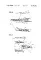
- FIG. 1is a cross sectional side view through an airfoil showing the airfoil variable cambering device of this invention
- FIG. 2is a perspective view of an aircraft wing partially cut away to show the variable cambering device positioned in the trailing edge of the wing;
- FIG. 3is a view in perspective of another aircraft wing showing the variable cambering device positioned spanwise along both leading and trailing edges thereof;
- FIG. 4is an exploded view in perspective of a portion of the variable cambering device
- FIG. 5is an enlarged view, partially in section, of the area 5 of FIG. 1;
- FIG. 6is a cross sectional view of an attachment node showing slidable connection of the airfoil's outer skin to the cambering device beam member, and taken along line 6--6 thereof;
- FIG. 7is an elevational view of the node of FIG. 6, taken along line 7--7 of FIG. 6;
- FIG. 8is a cross sectional view showing connection between the airfoil outer skin and the cambering device lower beam member taken along line 8--8 of FIG. 1;
- FIG. 9is a cross sectional view taken along line 9--9 of FIG. 1 showing the slidable connection at the airfoil trailing edge;
- FIG. 10is an elevational view showing use of the cambering device for varying the contour of a jet engine air inlet.
- FIG. 11is a side view of a jet engine exhaust nozzle showing use of the cambering device to vary the nozzle cross section.
- FIG. 12is a partial view in perspective of an aircraft empennage showing use of the invention to vary the camber of the empennage airfoil surfaces.
- a variable cambering device 20 of the inventionis shown positioned in an aircraft wing 22 in the trailing edge portion to form a rib means for the wing.
- Device 20is provided as a bendable structural beam 26 having as its airfoil or wing outer surface the upper and lower wing skins 28 and 30 slidably attached to the beam 26.
- the beamis longitudinally (or chordwise) divided into upper and lower beam members 34 and 36 respectively pivotally connected to wing spar 38 at hinge pivots 40 and 42.
- Each beam memberis positionally movable one with respect to the other to provide for changing the shape of the beam which permits it to be bent or flexed up or down thereby varying the camber of the airfoil and its outer surface as the position of each beam member is shifted with respect to the other about the hinges 40 and 42.
- the upper and lower beam members 34 and 36are movably connected one to the other by a bendable jackscrew means 46 which can be turned or revolved by motor means (not shown) operable to turn the jackscrew when desired through worm gear 48 bearing on shaft gear 50 at the forward end of the jackscrew shaft 52.
- Each beam member 34 and 36is constructed of three rigid beam member or truss chord segments 54a, b, c, d, e and f forming triangular segments, the segments of each member being arranged in-line and flexibly connected together by hinge pins 56 passing through mating knuckles 58 at hinges 60 to form each beam member as an articulated series of trusslike structural segments movable one with respect to the other, which provides for the bending or deflecting of the device about pivots 40 and 42.
- Each upper and lower beam member segment or chord segmenthas a beam cap portion 62 and a beam web portion 64, the web being triangular in concept so that the base of the triangle lies at the beam cap portion.
- Each upper segmenthas a yoke 65 at the apex of the triangle.
- a nut means 66is journaled in each yoke and pivotal on lugs 68 via bushings 69.
- the nutdefines interiorly threaded aperture 70.
- Each lower beam member segment or chord segmentis also substantially triangular in function with the base of the triangle forming a beam cap portion and lying along a portion of the airfoil outer surface, the beam web portion extending triangularly inwardly from the cap portion.
- the apex area of each triangular lower beam member segmentis constructed as an upwardly open, yoke-like box or U-shaped recess 72 each having forward and after ends or bulkheads 74 and 76.
- Defined through each bulkheadis an interiorly threaded hole 78 each provided with a mating bushing-like thrust bearing 80.
- Each recessis adapted to receive one of the yokes 65 and nut means 66, of an upper beam member segment thus providing for a strong connection of the segments of the upper beam member to the lower beam member through jackscrew means 46 to produce a strong, variably bendable beam means as an airfoil rib.
- the jackscrew means 46have a plurality of screws or screw shafts respectively designated 84, 86 and 88 having exterior threads 89.
- the screwsare flexibly connected together by universal joints 90 and 92 slidable telescopially on splines 94 and 96 so as to form flexible coupling means between each of the screws 84, 86 and 88.
- Each of these screwsis threadedly positioned in its associated threaded nut aperture 70 with ends of the screw shafts journalled in thrust bearings 80 in the bulkheads of recesses 72.
- a thrust collar 100 at each end of each screwprovides for transferring thrust at the bulkheads.
- Each of the screws 84, 86 and 88differs in the pitch of its screw threads 102 in the ratio of 1:2:3 and the recesses 72 are longer the greater the thread pitch to accommodate the difference in relative movement which each nut means 66 makes along its respective screw as the jackscrew shaft 52 is turned.
- the difference in relative movementcauses a progressively greater bending of the airfoil towards the trailing edge as will now be apparent. See the changed position of beam, airfoil and segments as shown in broken lines in FIG. 1.
- Each pair of oppositely arranged triangular-like segmentseffectively forms a beam truss bay or truss bay portion of the beam effective to form a complete load bearing section of the beam.
- Each truss bayhas as its beam caps the cap portions 62 and as its shear web the webs 64 connected by the jackscrew.
- the upper skin surface 28is slidably connected to the beam by free sliding connection thereto at nodes located at hinge pins 56 for the upper surface.
- the pinshave spherical heads embedded in cubes 108 made slidable in channels 110. Channels for each node are bolted by their flanges 112 to the upper skin (see FIGS. 6 and 7).
- the lower skinsare similarly connected with the lowr beam member 36 at nodes 116 as shown in FIG. 8. The connection is similar to that for the skin to upper beam member connections except that the lower connection nodes are approximately midway between ends of the lower beam member segments where headed node pins 120 attached thereto and slide in lower channels 122 bolted to the wing skin.
- the beamand thus the airfoil, is structurally rigid in all positions.
- the wing cambercannot be altered from any given position of contour by the application of external loads due to the inherent non-reversible characteristics of the jack-screw drive.
- FIG. 10showing inlet 140, and its use in an exhaust nozzle 150 for a jet engine or exhaust passage for a jet aircraft is seen in FIG. 11.
- FIG. 12shows the airfoil of the invention used in airfoil portions of an aircraft empennage.
- the airfoil skinis freely slidable with respect to the beam over substantially the full extent of such bendable rib means.
- the ribcan form a structural beam for the airfoil substantially independent of the airfoil skin but giving continuous structural support thereto over the length of the beam.
- chordwise length and/or height of one or more of the beam member segmentscan be made shorter or longer and/or the variation in travel differential between adjacent segments varied according to the particular camber and surface curvatures desired. Therefore, the invention makes possible use of variable camber airfoils which require airfoil surfaces whose curvature is a splined series of differing curvatures.
Landscapes
- Engineering & Computer Science (AREA)
- Mechanical Engineering (AREA)
- Aviation & Aerospace Engineering (AREA)
- Structures Of Non-Positive Displacement Pumps (AREA)
Abstract
Description
The invention relates to devices and method for altering the chamber and exterior contour of airfoils. As the development of high performance aircraft structures has advanced, it has been recognized for some time that airfoils used in such structures have improved efficiency and usefulness in some circumstances if the airfoil camber and its outer surface or skin curvatures can be varied to result in a different configuration or curvature. This is particularly desirable with supercritical wings in transonic aircraft in order to reduce drag to a minimum over the full operational speed range. However, while numerous devices have been proposed for producing variable camber devices, most are subject to undesirable limitations such as lack of structural strength, too great bulk for available space, have weight disadvantages, are undesirably complex or do not allow for the desired changes in curvature. Thus, while it is known to move an entire fixed contour portion of an airfoil, for example, the well known extension or deflection of leading or trailing edge flaps in an aircraft wing, such devices are usually limited to alteration of camber by the repositioning of such fixed geometry structure and are unable to vary camber and airfoil surface curvature smoothly and continuously over substantially the entire surface or extent thereof both chordwise and spanwise of the airfoil.
The present invention provides practical solutions to the above-referred-to drawbacks of prior structures and provide increased flexibility in the design of airfoils to have optimum contour over a greater range of flight conditions.
As used herein the term "airfoil" is intended to mean any surface or body used for the purpose of directing or deflecting an airflow and includes lifting body type airfoils, canards, flaps, vanes, ramps or other air directing or diverting surfaces. Airfoil camber is the mean line of curvature between the outer surfaces or skins of the airfoil.
In the present invention, it has been found that a variable camber airfoil can have its understructure, such as the typical chordwise extending airfoil rib for supporting the airfoil skin surfaces, provided as a bendable truss-like beam by dividing the beam longitudinally into generally opposed first and second beam members with the airfoil skin flexibility slidable thereover. When each beam member is divided into truss-like chord segments hinged together, then one beam member can be moved or repositioned generally chordwise, and its curvature changed, relative to the other members to cause the beam and thus the airfoil to deflect curvedly substantially the full chordwise length thereof and thus effect a smooth continuous variation in the airfoil camber and the closed curvature of its outer or skin surfaces. Jackscrew means are advantageously provided to movably connected one beam member to the other by connecting the segments of the one member with those of the opposite beam member and to move or positionally shift one or more segments of one beam member with respect to one or more other segments generally chordwise by non-uniform amounts along the beam length. When the jackscrew is arranged to connect the beam members along the neutral axis of the beam the instananeous force required to bend the airfoil against a given loading is minimized with resulting decrease in weight, bulk and strength requirements for the operative structure.
Chord segments of the beam members may beneficially be arranged as generally oppositely positioned pairs of beam member segments, each pair together forming a variable geometry truss by the height of the beam. So constructed, the distance along one or more diagonals of each such beam truss bay, i.e., between upper and lower caps of the beam at the outer surfaces of the airfoil rib means, may be varied to cause the beam, the airfoil, to assume the new contours with the airfoil skin bending uninterruptedly over the rib means at all degrees of curvature.
A plurality of the bendable airfoil rib means can be employed spanwise of the airfoil and one or more such rib means can be varied in contour to a different camber and surface curvature than one or more others of the rib means when it is desired to produce a twist in the airfoil surface in the spanwise direction.
The above and further objects and advantages of the invention will become more apparent from attention to the description following and the annexed drawings and explanation thereof depicting a preferred embodiment given by way of example only and not intended as limitative of the inventive concepts herein and wherein;
FIG. 1 is a cross sectional side view through an airfoil showing the airfoil variable cambering device of this invention;
FIG. 2 is a perspective view of an aircraft wing partially cut away to show the variable cambering device positioned in the trailing edge of the wing;
FIG. 3 is a view in perspective of another aircraft wing showing the variable cambering device positioned spanwise along both leading and trailing edges thereof;
FIG. 4 is an exploded view in perspective of a portion of the variable cambering device;
FIG. 5 is an enlarged view, partially in section, of thearea 5 of FIG. 1;
FIG. 6 is a cross sectional view of an attachment node showing slidable connection of the airfoil's outer skin to the cambering device beam member, and taken alongline 6--6 thereof;
FIG. 7 is an elevational view of the node of FIG. 6, taken alongline 7--7 of FIG. 6;
FIG. 8 is a cross sectional view showing connection between the airfoil outer skin and the cambering device lower beam member taken alongline 8--8 of FIG. 1;
FIG. 9 is a cross sectional view taken alongline 9--9 of FIG. 1 showing the slidable connection at the airfoil trailing edge;
FIG. 10 is an elevational view showing use of the cambering device for varying the contour of a jet engine air inlet; and
FIG. 11 is a side view of a jet engine exhaust nozzle showing use of the cambering device to vary the nozzle cross section.
FIG. 12 is a partial view in perspective of an aircraft empennage showing use of the invention to vary the camber of the empennage airfoil surfaces.
Referring to the drawings, in FIG. 1, avariable cambering device 20 of the invention is shown positioned in anaircraft wing 22 in the trailing edge portion to form a rib means for the wing.Device 20 is provided as a bendablestructural beam 26 having as its airfoil or wing outer surface the upper andlower wing skins beam 26. The beam is longitudinally (or chordwise) divided into upper andlower beam members wing spar 38 athinge pivots hinges
The upper andlower beam members worm gear 48 bearing onshaft gear 50 at the forward end of thejackscrew shaft 52.
Eachbeam member truss chord segments 54a, b, c, d, e and f forming triangular segments, the segments of each member being arranged in-line and flexibly connected together byhinge pins 56 passing throughmating knuckles 58 at hinges 60 to form each beam member as an articulated series of trusslike structural segments movable one with respect to the other, which provides for the bending or deflecting of the device aboutpivots beam cap portion 62 and abeam web portion 64, the web being triangular in concept so that the base of the triangle lies at the beam cap portion. Each upper segment has ayoke 65 at the apex of the triangle. A nut means 66 is journaled in each yoke and pivotal onlugs 68 viabushings 69. The nut defines interiorly threadedaperture 70.
Each lower beam member segment or chord segment is also substantially triangular in function with the base of the triangle forming a beam cap portion and lying along a portion of the airfoil outer surface, the beam web portion extending triangularly inwardly from the cap portion. The apex area of each triangular lower beam member segment is constructed as an upwardly open, yoke-like box or U-shaped recess 72 each having forward and after ends orbulkheads hole 78 each provided with a mating bushing-like thrust bearing 80. Each recess is adapted to receive one of theyokes 65 and nut means 66, of an upper beam member segment thus providing for a strong connection of the segments of the upper beam member to the lower beam member through jackscrew means 46 to produce a strong, variably bendable beam means as an airfoil rib.
It can be seen that the jackscrew means 46 have a plurality of screws or screw shafts respectively designated 84, 86 and 88 havingexterior threads 89. The screws are flexibly connected together byuniversal joints splines screws nut aperture 70 with ends of the screw shafts journalled inthrust bearings 80 in the bulkheads ofrecesses 72. Athrust collar 100 at each end of each screw provides for transferring thrust at the bulkheads. Each upper beam member segment of the other beam member and when the jackscrew means 46 is revolved the segment of one beam member is positionably moved or displaced generally chordwise of the airfoil with respect to its opposite segment. Each of thescrews recesses 72 are longer the greater the thread pitch to accommodate the difference in relative movement which each nut means 66 makes along its respective screw as thejackscrew shaft 52 is turned. The difference in relative movement causes a progressively greater bending of the airfoil towards the trailing edge as will now be apparent. See the changed position of beam, airfoil and segments as shown in broken lines in FIG. 1.
Each pair of oppositely arranged triangular-like segments effectively forms a beam truss bay or truss bay portion of the beam effective to form a complete load bearing section of the beam. Each truss bay has as its beam caps thecap portions 62 and as its shear web thewebs 64 connected by the jackscrew. By reference to the central pair ofchord segments nut 66 travels to the left on its associatedscrew 86 and diagonal AD lengthens.
Theupper skin surface 28 is slidably connected to the beam by free sliding connection thereto at nodes located athinge pins 56 for the upper surface. For this purpose the pins have spherical heads embedded incubes 108 made slidable inchannels 110. Channels for each node are bolted by theirflanges 112 to the upper skin (see FIGS. 6 and 7). The lower skins are similarly connected with thelowr beam member 36 atnodes 116 as shown in FIG. 8. The connection is similar to that for the skin to upper beam member connections except that the lower connection nodes are approximately midway between ends of the lower beam member segments where headednode pins 120 attached thereto and slide inlower channels 122 bolted to the wing skin.
Connection at the trailing edge between upper and lower skins is accomplished by the mating tongue and groove sliding connection of FIG. 9. Thus, the after edge ofbeam member segment 54c has agroove 126 and thesegment 54f has atongue 128 slidable therein, the upper and lower wing skins being respectively bolted to the trailing edges of these segments as seen in the Figure.
It is inherent to the construction that the beam, and thus the airfoil, is structurally rigid in all positions. Thus, it will be understood that in the embodiment shown the wing camber cannot be altered from any given position of contour by the application of external loads due to the inherent non-reversible characteristics of the jack-screw drive.
The use of one of the airfoil devices of the invention in an aircraft jet engine inlet will be apparent from FIG. 10showing inlet 140, and its use in anexhaust nozzle 150 for a jet engine or exhaust passage for a jet aircraft is seen in FIG. 11.
FIG. 12 shows the airfoil of the invention used in airfoil portions of an aircraft empennage.
It will be appreciated that the airfoil skin is freely slidable with respect to the beam over substantially the full extent of such bendable rib means. When necessary, then, the rib can form a structural beam for the airfoil substantially independent of the airfoil skin but giving continuous structural support thereto over the length of the beam.
It will also be appreciated that the chordwise length and/or height of one or more of the beam member segments can be made shorter or longer and/or the variation in travel differential between adjacent segments varied according to the particular camber and surface curvatures desired. Therefore, the invention makes possible use of variable camber airfoils which require airfoil surfaces whose curvature is a splined series of differing curvatures.
Various modifications may be made by those skilled in the art without departing from the spirit and scope of the herein described inventive concepts as defined in the appended claims.
Claims (27)
1. An airfoil variable cambering device for varying the camber and the outer surface curvature of an airfoil in a smooth, continuous fashion over substantially the entirety thereof which comprises:
airfoil rib means positioned in the airfoil for giving structural support thereto,
outer directed portions of the rib means approximately defining a major portion of the airfoil cross section;
airfoil outer skin means arranged over said outer directed portions of said rib means to form substantially smoothly continuous outer surfaces for the airfoil;
means connecting said skin means to said rib means;
the rib means being formed as a bendable beam divided into first and second beam members each extending substantially the length of the beam;
said beam members being positionally movable chordwise one with respect to the other so as to alter the beam contour; and
jackscrew means connecting said first and second beam members and rotatable to effect said chordwise movement of said beam members one with respect to the other;
whereby rotation of the jackscrew means causes one of said beam members to be positionally shifted relative to the other beam member to provide a smooth continuous variation in the camber of the airfoil and the curvature of its outer surface.
2. The variable cambering device of claim 1 in which said airfoil skin means is connected with said bendable rib means to freely and flexibly slide thereover.
3. The variable cambering device of claim 2 in which said skin means over said rib means is slidable relative thereto over substantially the full chordwise extent of the rib means.
4. The variable cambering device of claim 1 in which the mean lines of curvature of said first and second beam members are variable one with respect to the other.
5. The variable cambering device of claim 1 in which said beam members are respectively hinged to and pivotable about axes at opposite outer surface areas of the airfoil.
6. The device of claim 1 in which chord segments of one of said beam members are arranged generally opposite chord segments of the other beam member and positionally movable relative thereto to form generally opposed pairs of segments, each pair together forming a truss bay portion of the beam substantially the full height thereof, the geometry of said truss bay portion being variable by shifting the position of one of said segments with respect to the other of said segments whereby to lengthen or shorten the length of a diagonal of said truss bay portion.
7. The variable cambering device of claim 6 in which the extent of said positional shifting is variable as between pairs of said oppositely positioned chord segments.
8. The variable cambering device of claim 1 in which means are provided for turning said jackscrew means in both forward and reverse directions.
9. The variable cambering device of claim 1 in which said jackscrew means comprises a jackscrew shaft having a plurality of spaced apart threaded shaft sections serially flexibly connected along the axis of the shaft, the pitch of the threads varying as between at least two of said shaft sections.
10. The variable cambering device of claim 9 in which there are three of said threaded shaft sections, the threads thereof respectively varying in pitch by a ratio of 1:2:3.
11. The variable cambering device of claim 9 in which at least one of said threaded shaft sections is movable generally chordwise with respect to another of said threaded shafts along the axis of said jackscrew means.
12. The variable cambering device of claim 1 in which said jackscrew means connects said relatively movable beam members along approximately the longitudinal neutral axis of said beam.
13. An airfoil structure having means therein for varying the camber and outer surface curvatures thereof in a smooth continuous fashion which comprises:
airfoil rib means;
airfoil outer skin means arranged thereover said rib means and said outer skin means together forming an airfoil;
outer directed portions of the rib means approximately defining a substantial portion of said airfoil cross section with said skin means slidably connected over said rib means
the rib means being formed as a bendable beam divided into first and second beam members each extending substantially the length of the beam;
said beam members being positionally movable chordwise one with respect to the other so as to alter the beam contour; and
jackscrew means connecting said first and second beam members and rotatable to effect said chordwise movement of said beam members one with respect to the other;
whereby rotation of the jackscrew means causes one of said beam members to be positionally shifted relative to the other beam member to provide a smooth continuous variation in the camber of the airfoil and the curvature of its outer surface.
14. The airfoil of claim 13 in which a plurality of said rib means are positioned in the airfoil spanwise thereof.
15. The airfoil of claim 13 in which said airfoil forms a substantial portion of an aerodynamic lifting body.
16. The airfoil of claim 13 in which said airfoil forms the trailing edge portion of an aerodynamic lifting body.
17. The airfoil of claim 15 in which said lifting body is an aircraft wing.
18. The airfoil of claim 13 in which the airfoil is a portion of an aircraft empennage.
19. The airfoil of claim 13 in which the airfoil forms a portion of a jet engine exhaust nozzle.
20. The airfoil of claim 13 in which the airfoil forms a portion of an aircraft jet engine air intake.
21. The airfoil of claim 13 in which there are a plurality of said variable cambering means spanwise of said airfoil, at least one of said variable cambering means being bendable to greater or lesser degrees than at least one other of said variable cambering means whereby to impart a spanwise twist along said airfoil.
22. Method for varying the camber of an airfoil to produce smooth continuous variations in curvature both of the camber and the airfoil outer surfaces comprising:
providing a chordwise rib means as support for an airfoil outer surface in the form of a bendable beam divided into first and second beam members extending substantially the length of the beam;
each beam member having a plurality of trusslike chord segments hinged together to provide for flexure in each of said beam members and each beam member positionally shiftable generally chordwise one with respect to the other along their lengths,
said first and second beam members being connected together by a flexibly rotatable jackscrew means;
turning said jackscrew means, and
repositioning one of said beam members generally chordwise with respect to the other beam member to alter the position and curvature of one beam member with respect to the other beam member to effect a change in beam contour;
whereby the camber and exterior surface curvature of the airfoil are smoothly and continuously variable from previous to new positions and contours.
23. The method of claim 22 in which said airfoil outer surface is a skin means slidable with respect to said rib means and said repositioning of one of said beam members with respect to the other is simultaneous with the sliding of said skin means relative to outer directed portions of said rib means.
24. The method of claim 22 in which chord segments of one of said beam members are arranged generally opposite chord segments of the other beam member and positionally movable relative thereto to form generally opposed pairs of segments, each pair together forming a truss bay portion of the beam substantially the full height thereof, and said repositioning of one of said beam members with respect to the other beam member is accomplished by shifting one of the segments of at least one such pair generally chordwise relative to the other segment thereof so as to lengthen or shorten a diagonal of said truss bay portion between the cap portions of said beam.
25. The method of claim 24 in which said generally chordwise positional movement between the chord segments of a segment pair is variable.
26. The method of claim 24 in which said chordwise positional movement between the chord segments of a pair is variable relative to the positional movement between segments of another said segment pair.
27. The method of claim 22 in which a plurality of said bendable beam rib means are positioned spanwise of the airfoil and the camber of the airfoil is varied along the spanwise length by varying the bending of at least one of said rib means to a greater or lesser degree than at least one other of said rib means.
Priority Applications (1)
| Application Number | Priority Date | Filing Date | Title |
|---|---|---|---|
| US05/879,650US4247066A (en) | 1978-02-21 | 1978-02-21 | Airfoil variable cambering device and method |
Applications Claiming Priority (1)
| Application Number | Priority Date | Filing Date | Title |
|---|---|---|---|
| US05/879,650US4247066A (en) | 1978-02-21 | 1978-02-21 | Airfoil variable cambering device and method |
Publications (1)
| Publication Number | Publication Date |
|---|---|
| US4247066Atrue US4247066A (en) | 1981-01-27 |
Family
ID=25374590
Family Applications (1)
| Application Number | Title | Priority Date | Filing Date |
|---|---|---|---|
| US05/879,650Expired - LifetimeUS4247066A (en) | 1978-02-21 | 1978-02-21 | Airfoil variable cambering device and method |
Country Status (1)
| Country | Link |
|---|---|
| US (1) | US4247066A (en) |
Cited By (75)
| Publication number | Priority date | Publication date | Assignee | Title |
|---|---|---|---|---|
| FR2503661A1 (en)* | 1981-04-08 | 1982-10-15 | Ver Flugtechnische Werke | METHOD FOR OPTIMIZING THE CRUISE FLIGHT CONDITION OF TRANSSONIC WING AIRCRAFT AND DEVICE FOR IMPLEMENTING SAID METHOD |
| US4795111A (en)* | 1987-02-17 | 1989-01-03 | Moller International, Inc. | Robotic or remotely controlled flying platform |
| US4899284A (en)* | 1984-09-27 | 1990-02-06 | The Boeing Company | Wing lift/drag optimizing system |
| US4979699A (en)* | 1989-05-26 | 1990-12-25 | Grumman Aerospace Corporation | Flight control augmentation inlet device |
| US5033693A (en)* | 1988-12-14 | 1991-07-23 | The Boeing Company | Single-piece, flexible inlet ramp |
| DE4007694A1 (en)* | 1990-03-10 | 1991-09-12 | Deutsche Forsch Luft Raumfahrt | Variable-profile aircraft wing - has front profiled component hinging where flow is deflected for high lift |
| US5651513A (en)* | 1995-03-01 | 1997-07-29 | Northrop Grumman Corporation | Linear flap drive system |
| DE19653851A1 (en)* | 1996-12-21 | 1998-06-25 | Daimler Benz Ag | Aerodynamic body with internal adjustment drive |
| FR2767111A1 (en) | 1997-07-31 | 1999-02-12 | Daimler Benz Ag | Aircraft wing with landing flap |
| US5887828A (en)* | 1997-11-13 | 1999-03-30 | Northrop Grumman Corporation | Seamless mission adaptive control surface |
| GB2332894A (en)* | 1997-09-19 | 1999-07-07 | Deutsch Zentr Luft & Raumfahrt | Variable profile aerofoil |
| GB2332893A (en)* | 1997-09-19 | 1999-07-07 | Deutsch Zentr Luft & Raumfahrt | Variable profile aerofoil |
| US5947422A (en)* | 1997-04-29 | 1999-09-07 | Mcdonnell Douglas | Tail for an aircraft |
| US6045096A (en)* | 1998-06-30 | 2000-04-04 | Rinn; Aaron | Variable camber airfoil |
| US6068219A (en)* | 1998-04-13 | 2000-05-30 | Northrop Grumman Corporation | Single surface multi axis aircraft control |
| DE19936721A1 (en)* | 1999-08-06 | 2001-02-15 | Deutsch Zentr Luft & Raumfahrt | Support wing profile for commercial aircraft; has profiled edge with skin parts and perpendicular ribs having planar elements connected between skin parts by rotating joints |
| US6244542B1 (en)* | 1999-07-20 | 2001-06-12 | Northrop Grumman Corporation | Rotor driven edge |
| US20020100842A1 (en)* | 2000-11-11 | 2002-08-01 | Juan Perez | Mechanism for at least regionally adjusting the curvature of airfoil wings |
| US6481667B1 (en) | 2001-03-05 | 2002-11-19 | Northrop Grumman Corporation | System and method for deflecting an aerodynamic control surface |
| US20030168057A1 (en)* | 2001-12-14 | 2003-09-11 | Inhale Therapeutic Systems, Inc. | Electronically controllable aerosol delivery |
| US20040003866A1 (en)* | 2002-06-27 | 2004-01-08 | Nektar Therapeutics | Apparatus and method for filling a receptacle with powder |
| US20040156792A1 (en)* | 2002-12-31 | 2004-08-12 | Nektar Therapeutics | Pharmaceutical formulation with an insoluble active agent |
| US20040176391A1 (en)* | 2002-12-31 | 2004-09-09 | Nektar Therapeutics | Aerosolizable pharmaceutical formulation for fungal infection therapy |
| US20040206350A1 (en)* | 2002-12-19 | 2004-10-21 | Nektar Therapeutics | Aerosolization apparatus with non-circular aerosolization chamber |
| WO2004110861A1 (en)* | 2003-06-07 | 2004-12-23 | Airbus Deutschland Gmbh | Wing, especially a carrier wing of an aeroplane, having an adaptable profile |
| US20050000518A1 (en)* | 2003-04-09 | 2005-01-06 | Nektar Therapeutics | Aerosolization apparatus with capsule puncture alignment guide |
| US20050022813A1 (en)* | 2002-12-31 | 2005-02-03 | Nektar Therapeutics (Formerly Inhale Therapeutic Systems, Inc.) | Aerosolization apparatus with rotating capsule |
| US20050056280A1 (en)* | 2002-12-31 | 2005-03-17 | Nektar Therapeutics | Receptacle for an aerosolizable pharmaceutical formulation |
| US20050150492A1 (en)* | 2003-04-09 | 2005-07-14 | Nektar Therapeutics | Aerosolization apparatus with air inlet shield |
| US20050214224A1 (en)* | 2003-11-04 | 2005-09-29 | Nektar Therapeutics | Lipid formulations for spontaneous drug encapsulation |
| US20050236296A1 (en)* | 2002-12-30 | 2005-10-27 | Nektar Therapeutics (Formerly Inhale Therapeutic Systems, Inc.) | Carry case for aerosolization apparatus |
| US20060025355A1 (en)* | 2004-06-21 | 2006-02-02 | Nektar Therapeutics | Compositions comprising amphotericin B, methods, and systems |
| US20060159625A1 (en)* | 2000-05-10 | 2006-07-20 | Nektar Therapeutics | Formulation for pulmonary administration of antifungal agents, and associated methods of manufacture and use |
| US20060237596A1 (en)* | 2004-09-21 | 2006-10-26 | Airbus Deutschland Gmbh | Wing, particularly airfoil of an aircraft, having changeable profile |
| US20070123477A1 (en)* | 2004-06-21 | 2007-05-31 | Richard Malcolmson | Compositions comprising amphotericin B, methods, and systems |
| EP1637450A3 (en)* | 2004-09-21 | 2008-01-09 | Airbus Deutschland GmbH | Wing, in particular aircraft wing, with variable profile |
| WO2008006831A1 (en)* | 2006-07-11 | 2008-01-17 | Airbus Deutschland Gmbh | Trimmable horizontal stabilizer |
| US20090020644A1 (en)* | 2006-09-24 | 2009-01-22 | Young Kendall G | Contra-bevel driven control surface |
| US20090032427A1 (en)* | 2005-09-29 | 2009-02-05 | Nektar Therapeutics | Receptacles and Kits, Such as for Dry Powder Packaging |
| WO2009061478A1 (en)* | 2007-11-06 | 2009-05-14 | Flexsys, Inc. | Active control surfaces for wind turbine blades |
| US20100152926A1 (en)* | 2007-04-13 | 2010-06-17 | The Boeing Company | Dynamic adjustment of wing surfaces for variable camber |
| US20100200689A1 (en)* | 2009-02-10 | 2010-08-12 | Robert Erik Grip | Aircraft with a pressurized vessel |
| US20100224734A1 (en)* | 2009-03-05 | 2010-09-09 | Robert Erik Grip | Mechanism for changing the shape of a control surface |
| US20100287884A1 (en)* | 2007-10-25 | 2010-11-18 | Sangita Seshadri | Powder conditioning of unit dose drug packages |
| US20110123626A1 (en)* | 2008-05-15 | 2011-05-26 | Novartis Ag | Pulmonary delivery of a fluoroquinolone |
| US20110166063A1 (en)* | 2008-09-19 | 2011-07-07 | Nektar Therapeutics | Polymer conjugates of therapeutic peptides |
| US20110171312A1 (en)* | 2008-09-19 | 2011-07-14 | Nektar Therapeutics | Modified therapeutic peptides, methods of their preparation and use |
| US8382045B2 (en) | 2009-07-21 | 2013-02-26 | The Boeing Company | Shape-changing control surface |
| US20130099049A1 (en)* | 2011-10-21 | 2013-04-25 | Jack W. Reany | Aircraft wing with flexible skins |
| US20130099050A1 (en)* | 2011-10-21 | 2013-04-25 | Terry M. Sanderson | Aircraft wing with knuckled rib structure |
| US8650811B2 (en) | 2011-02-04 | 2014-02-18 | The Boeing Company | Solar collector frame |
| US8869794B1 (en) | 2003-04-09 | 2014-10-28 | Novartis Pharma Ag | Aerosolization apparatus with capsule puncturing member |
| WO2014193511A3 (en)* | 2013-03-07 | 2015-01-22 | Massachusetts Institute Of Technology | Flexural digital material construction and transduction |
| WO2015007258A1 (en)* | 2013-07-17 | 2015-01-22 | Airbus Defence and Space GmbH | Changeable wing profile |
| US8974828B2 (en) | 2009-03-18 | 2015-03-10 | Incarda Therapeutics, Inc. | Unit doses, aerosols, kits, and methods for treating heart conditions by pulmonary administration |
| US9506485B2 (en) | 2011-11-04 | 2016-11-29 | Massachusetts Institute Of Technology | Hierarchical functional digital materials |
| US9566758B2 (en) | 2010-10-19 | 2017-02-14 | Massachusetts Institute Of Technology | Digital flexural materials |
| US9690286B2 (en) | 2012-06-21 | 2017-06-27 | Massachusetts Institute Of Technology | Methods and apparatus for digital material skins |
| US9809001B2 (en) | 2010-10-19 | 2017-11-07 | Massachusetts Institute Of Technology | Flexural digital material construction and transduction |
| US9944356B1 (en) | 2009-03-25 | 2018-04-17 | Alexander T. Wigley | Shape shifting foils |
| WO2018209107A1 (en) | 2017-05-10 | 2018-11-15 | Incarda Therapeutics, Inc. | Unit doses, aerosols, kits, and methods for treating heart conditions by pulmonary administration |
| US10288008B2 (en)* | 2012-03-05 | 2019-05-14 | The Boeing Company | Sandwich structure having hinge assemblies for accommodating differential in-plane expansion of face sheets |
| US10318903B2 (en) | 2016-05-06 | 2019-06-11 | General Electric Company | Constrained cash computing system to optimally schedule aircraft repair capacity with closed loop dynamic physical state and asset utilization attainment control |
| WO2019183470A2 (en) | 2018-03-22 | 2019-09-26 | Incarda Therapeutics, Inc. | A novel method to slow ventricular rate |
| US10442525B2 (en)* | 2016-05-07 | 2019-10-15 | Optivector Ltd | Rotor or propeller blade with dynamically variable geometry and other properties |
| US10577076B1 (en)* | 2019-04-19 | 2020-03-03 | Leo Edward Wylonis | Shape-shifting aircraft wing actuated via polymer artificial muscle driven twisting wing ribs |
| US10660578B2 (en) | 2016-02-01 | 2020-05-26 | Incarda Therapeutics, Inc. | Combining electronic monitoring with inhaled pharmacological therapy to manage cardiac arrhythmias including atrial fibrillation |
| US11007185B2 (en) | 2019-08-01 | 2021-05-18 | Incarda Therapeutics, Inc. | Antiarrhythmic formulation |
| GB2605195A (en)* | 2021-03-26 | 2022-09-28 | Airbus Operations Ltd | Trailing edge panel support with movable connector |
| US11932389B1 (en)* | 2020-01-06 | 2024-03-19 | United States Of America As Represented By The Secretary Of The Air Force | Morphing airfoil |
| US11993376B2 (en) | 2021-03-26 | 2024-05-28 | Airbus Operations Limited | Trailing edge panel support with biasing arrangement |
| US12071239B2 (en) | 2021-03-26 | 2024-08-27 | Airbus Operations Limited | Aircraft wing with trailing edge panel |
| US12097953B2 (en) | 2021-03-26 | 2024-09-24 | Airbus Operations Limited | Trailing edge panel support |
| CN119037703A (en)* | 2024-09-27 | 2024-11-29 | 南京航空航天大学 | Driving device for variable chord length wing |
| CN119190340A (en)* | 2024-10-21 | 2024-12-27 | 南京航空航天大学 | A driving device for generating wing twist |
Citations (5)
| Publication number | Priority date | Publication date | Assignee | Title |
|---|---|---|---|---|
| US1365346A (en)* | 1920-07-02 | 1921-01-11 | Schenkel Gottfried | Adjusting device for aeroplanes |
| US1868748A (en)* | 1931-11-28 | 1932-07-26 | Herbert J Hogan | Variable camber airfoil |
| DE2041145A1 (en)* | 1969-09-09 | 1971-04-22 | Richard Dilo | Control profile for all types of aircraft |
| US3704828A (en)* | 1969-12-16 | 1972-12-05 | Hamburger Flugzeubau Gmbh | Aircraft fan with outflow deflectors |
| US4012013A (en)* | 1976-02-05 | 1977-03-15 | The Boeing Company | Variable camber inlet for supersonic aircraft |
- 1978
- 1978-02-21USUS05/879,650patent/US4247066A/ennot_activeExpired - Lifetime
Patent Citations (5)
| Publication number | Priority date | Publication date | Assignee | Title |
|---|---|---|---|---|
| US1365346A (en)* | 1920-07-02 | 1921-01-11 | Schenkel Gottfried | Adjusting device for aeroplanes |
| US1868748A (en)* | 1931-11-28 | 1932-07-26 | Herbert J Hogan | Variable camber airfoil |
| DE2041145A1 (en)* | 1969-09-09 | 1971-04-22 | Richard Dilo | Control profile for all types of aircraft |
| US3704828A (en)* | 1969-12-16 | 1972-12-05 | Hamburger Flugzeubau Gmbh | Aircraft fan with outflow deflectors |
| US4012013A (en)* | 1976-02-05 | 1977-03-15 | The Boeing Company | Variable camber inlet for supersonic aircraft |
Cited By (129)
| Publication number | Priority date | Publication date | Assignee | Title |
|---|---|---|---|---|
| NL8105237A (en)* | 1981-04-08 | 1982-11-01 | Ver Flugtechnische Werke | METHOD FOR OPTIMIZING THE CROSS-FLIGHT CONDITION OF AIRCRAFT WITH TRANSSONIC WINGS, AND AN APPARATUS FOR USING THE METHOD |
| FR2503661A1 (en)* | 1981-04-08 | 1982-10-15 | Ver Flugtechnische Werke | METHOD FOR OPTIMIZING THE CRUISE FLIGHT CONDITION OF TRANSSONIC WING AIRCRAFT AND DEVICE FOR IMPLEMENTING SAID METHOD |
| US4899284A (en)* | 1984-09-27 | 1990-02-06 | The Boeing Company | Wing lift/drag optimizing system |
| US4795111A (en)* | 1987-02-17 | 1989-01-03 | Moller International, Inc. | Robotic or remotely controlled flying platform |
| US5033693A (en)* | 1988-12-14 | 1991-07-23 | The Boeing Company | Single-piece, flexible inlet ramp |
| US4979699A (en)* | 1989-05-26 | 1990-12-25 | Grumman Aerospace Corporation | Flight control augmentation inlet device |
| DE4007694A1 (en)* | 1990-03-10 | 1991-09-12 | Deutsche Forsch Luft Raumfahrt | Variable-profile aircraft wing - has front profiled component hinging where flow is deflected for high lift |
| US5651513A (en)* | 1995-03-01 | 1997-07-29 | Northrop Grumman Corporation | Linear flap drive system |
| DE19653851C2 (en)* | 1996-12-21 | 1999-09-02 | Daimler Chrysler Ag | Aerodynamic body with internal actuators |
| DE19653851A1 (en)* | 1996-12-21 | 1998-06-25 | Daimler Benz Ag | Aerodynamic body with internal adjustment drive |
| US6070834A (en)* | 1996-12-21 | 2000-06-06 | Daimlerchrysler Ag | Aerodynamic body with internal actuating drives |
| US5947422A (en)* | 1997-04-29 | 1999-09-07 | Mcdonnell Douglas | Tail for an aircraft |
| US6076775A (en)* | 1997-07-31 | 2000-06-20 | Daimlerchrysler Ag | Airfoil with a landing flap having a flexible trailing edge |
| DE19732953C1 (en)* | 1997-07-31 | 1999-03-11 | Daimler Benz Ag | Wing with flap |
| GB2331734B (en)* | 1997-07-31 | 2002-01-16 | Daimler Benz Ag | Aerofoil having a landing flap |
| GB2331734A (en)* | 1997-07-31 | 1999-06-02 | Daimler Benz Ag | Aerofoil having a movable and bendable landing flap |
| FR2767111A1 (en) | 1997-07-31 | 1999-02-12 | Daimler Benz Ag | Aircraft wing with landing flap |
| US6164599A (en)* | 1997-09-19 | 2000-12-26 | Deutsches Zentrum Fur Luft-Und Raumfahrt E.V. | Aerofoil profile with variable profile adaptation |
| GB2332894A (en)* | 1997-09-19 | 1999-07-07 | Deutsch Zentr Luft & Raumfahrt | Variable profile aerofoil |
| US6138956A (en)* | 1997-09-19 | 2000-10-31 | Deutsches Zentrum Fur Luft-Und Raumfahrt E.V. | Aerofoil profile with variable profile adaptation |
| GB2332893B (en)* | 1997-09-19 | 2001-10-17 | Deutsch Zentr Luft & Raumfahrt | Aerofoil profile with variable profile adaptation |
| GB2332893A (en)* | 1997-09-19 | 1999-07-07 | Deutsch Zentr Luft & Raumfahrt | Variable profile aerofoil |
| GB2332894B (en)* | 1997-09-19 | 2001-10-17 | Deutsch Zentr Luft & Raumfahrt | Aerofoil profile member with variable profile adaptation |
| US5887828A (en)* | 1997-11-13 | 1999-03-30 | Northrop Grumman Corporation | Seamless mission adaptive control surface |
| US6068219A (en)* | 1998-04-13 | 2000-05-30 | Northrop Grumman Corporation | Single surface multi axis aircraft control |
| US6227498B1 (en) | 1998-04-13 | 2001-05-08 | Northrop Grumman Corporation | Single surface independent aircraft control |
| US6045096A (en)* | 1998-06-30 | 2000-04-04 | Rinn; Aaron | Variable camber airfoil |
| US6244542B1 (en)* | 1999-07-20 | 2001-06-12 | Northrop Grumman Corporation | Rotor driven edge |
| DE19936721B4 (en)* | 1999-08-06 | 2005-09-15 | Deutsches Zentrum für Luft- und Raumfahrt e.V. | Wing profile with adaptive warping |
| DE19936721A1 (en)* | 1999-08-06 | 2001-02-15 | Deutsch Zentr Luft & Raumfahrt | Support wing profile for commercial aircraft; has profiled edge with skin parts and perpendicular ribs having planar elements connected between skin parts by rotating joints |
| US20060159625A1 (en)* | 2000-05-10 | 2006-07-20 | Nektar Therapeutics | Formulation for pulmonary administration of antifungal agents, and associated methods of manufacture and use |
| US8404217B2 (en) | 2000-05-10 | 2013-03-26 | Novartis Ag | Formulation for pulmonary administration of antifungal agents, and associated methods of manufacture and use |
| US20020100842A1 (en)* | 2000-11-11 | 2002-08-01 | Juan Perez | Mechanism for at least regionally adjusting the curvature of airfoil wings |
| EP1205383A3 (en)* | 2000-11-11 | 2003-05-14 | EADS Deutschland Gmbh | Mechanism for modifying the camber of at least a part of an aircraft wing |
| US6644599B2 (en)* | 2000-11-11 | 2003-11-11 | Eads Deutschland Gmbh | Mechanism for at least regionally adjusting the curvature of airfoil wings |
| US6481667B1 (en) | 2001-03-05 | 2002-11-19 | Northrop Grumman Corporation | System and method for deflecting an aerodynamic control surface |
| US20030168057A1 (en)* | 2001-12-14 | 2003-09-11 | Inhale Therapeutic Systems, Inc. | Electronically controllable aerosol delivery |
| US6941980B2 (en) | 2002-06-27 | 2005-09-13 | Nektar Therapeutics | Apparatus and method for filling a receptacle with powder |
| US20040003866A1 (en)* | 2002-06-27 | 2004-01-08 | Nektar Therapeutics | Apparatus and method for filling a receptacle with powder |
| US20040206350A1 (en)* | 2002-12-19 | 2004-10-21 | Nektar Therapeutics | Aerosolization apparatus with non-circular aerosolization chamber |
| US20050236296A1 (en)* | 2002-12-30 | 2005-10-27 | Nektar Therapeutics (Formerly Inhale Therapeutic Systems, Inc.) | Carry case for aerosolization apparatus |
| US20040156792A1 (en)* | 2002-12-31 | 2004-08-12 | Nektar Therapeutics | Pharmaceutical formulation with an insoluble active agent |
| US7669596B2 (en) | 2002-12-31 | 2010-03-02 | Novartis Pharma Ag | Aerosolization apparatus with rotating capsule |
| US20050056280A1 (en)* | 2002-12-31 | 2005-03-17 | Nektar Therapeutics | Receptacle for an aerosolizable pharmaceutical formulation |
| US20050022813A1 (en)* | 2002-12-31 | 2005-02-03 | Nektar Therapeutics (Formerly Inhale Therapeutic Systems, Inc.) | Aerosolization apparatus with rotating capsule |
| US20040176391A1 (en)* | 2002-12-31 | 2004-09-09 | Nektar Therapeutics | Aerosolizable pharmaceutical formulation for fungal infection therapy |
| US7559325B2 (en) | 2003-04-09 | 2009-07-14 | Novartis Pharma Ag | Aerosolization apparatus with air inlet shield |
| US20050000518A1 (en)* | 2003-04-09 | 2005-01-06 | Nektar Therapeutics | Aerosolization apparatus with capsule puncture alignment guide |
| US20050150492A1 (en)* | 2003-04-09 | 2005-07-14 | Nektar Therapeutics | Aerosolization apparatus with air inlet shield |
| US8069851B2 (en) | 2003-04-09 | 2011-12-06 | Novartis Ag | Aeorosolization apparatus with air inlet shield |
| US20090260623A1 (en)* | 2003-04-09 | 2009-10-22 | Novartis Pharma Ag | Aeorosolization apparatus with air inlet shield |
| US8869794B1 (en) | 2003-04-09 | 2014-10-28 | Novartis Pharma Ag | Aerosolization apparatus with capsule puncturing member |
| USRE47526E1 (en) | 2003-04-09 | 2019-07-23 | BGP Products | Aerosolization apparatus with air inlet shield |
| US11484671B2 (en) | 2003-04-09 | 2022-11-01 | Bgp Products Operations Gmbh | Aerosolization apparatus with capsule puncture alignment guide |
| US10207066B2 (en) | 2003-04-09 | 2019-02-19 | Bgp Products Operations Gmbh | Aerosolization apparatus with capsule puncture alignment guide |
| WO2004110861A1 (en)* | 2003-06-07 | 2004-12-23 | Airbus Deutschland Gmbh | Wing, especially a carrier wing of an aeroplane, having an adaptable profile |
| US7699270B2 (en) | 2003-06-07 | 2010-04-20 | Airbus Deutschland Gmbh | Wing, especially a carrier wing of an airplane, having an adaptable profile |
| US20050214224A1 (en)* | 2003-11-04 | 2005-09-29 | Nektar Therapeutics | Lipid formulations for spontaneous drug encapsulation |
| US20060025355A1 (en)* | 2004-06-21 | 2006-02-02 | Nektar Therapeutics | Compositions comprising amphotericin B, methods, and systems |
| US7326691B2 (en) | 2004-06-21 | 2008-02-05 | Nektar Therapeutics | Compositions comprising amphotericin B, methods, and systems |
| US8513204B2 (en) | 2004-06-21 | 2013-08-20 | Novartis Ag | Compositions comprising amphotericin B, mehods and systems |
| US20070123477A1 (en)* | 2004-06-21 | 2007-05-31 | Richard Malcolmson | Compositions comprising amphotericin B, methods, and systems |
| US20060237596A1 (en)* | 2004-09-21 | 2006-10-26 | Airbus Deutschland Gmbh | Wing, particularly airfoil of an aircraft, having changeable profile |
| US7530533B2 (en)* | 2004-09-21 | 2009-05-12 | Airbus Deutschland Gmbh | Wing, particularly airfoil of an aircraft, having changeable profile |
| DE102004045651B4 (en)* | 2004-09-21 | 2010-09-16 | Airbus Deutschland Gmbh | Wing, in particular wing of an aircraft, with variable profile |
| EP1637450A3 (en)* | 2004-09-21 | 2008-01-09 | Airbus Deutschland GmbH | Wing, in particular aircraft wing, with variable profile |
| US20070152106A9 (en)* | 2004-09-21 | 2007-07-05 | Airbus Deutschland Gmbh | Wing, particularly airfoil of an aircraft, having changeable profile |
| US20090032427A1 (en)* | 2005-09-29 | 2009-02-05 | Nektar Therapeutics | Receptacles and Kits, Such as for Dry Powder Packaging |
| US20090289144A1 (en)* | 2006-07-11 | 2009-11-26 | Airbus Deutschland Gmbh | Trimmable horizontal stabilizer |
| DE102006032003B4 (en)* | 2006-07-11 | 2015-10-22 | Airbus Operations Gmbh | Trimmable tailplane |
| WO2008006831A1 (en)* | 2006-07-11 | 2008-01-17 | Airbus Deutschland Gmbh | Trimmable horizontal stabilizer |
| US7963485B2 (en) | 2006-07-11 | 2011-06-21 | Airbus Operations Gmbh | Trimmable horizontal stabilizer |
| US7731123B2 (en)* | 2006-09-24 | 2010-06-08 | Lockheed Martin Corporation | Contra-bevel driven control surface |
| US20090020644A1 (en)* | 2006-09-24 | 2009-01-22 | Young Kendall G | Contra-bevel driven control surface |
| US8447445B2 (en)* | 2007-04-13 | 2013-05-21 | The Boeing Company | Dynamic adjustment of wing surfaces for variable camber |
| US20100152926A1 (en)* | 2007-04-13 | 2010-06-17 | The Boeing Company | Dynamic adjustment of wing surfaces for variable camber |
| US20100287884A1 (en)* | 2007-10-25 | 2010-11-18 | Sangita Seshadri | Powder conditioning of unit dose drug packages |
| WO2009061478A1 (en)* | 2007-11-06 | 2009-05-14 | Flexsys, Inc. | Active control surfaces for wind turbine blades |
| US20100259046A1 (en)* | 2007-11-06 | 2010-10-14 | Sridhar Kota | Active control surfaces for wind turbine blades |
| US20110123626A1 (en)* | 2008-05-15 | 2011-05-26 | Novartis Ag | Pulmonary delivery of a fluoroquinolone |
| US9155732B2 (en) | 2008-05-15 | 2015-10-13 | Novartis Ag | Pulmonary delivery of a fluoroquinolone |
| US8834930B2 (en) | 2008-05-15 | 2014-09-16 | Novartis Ag | Pulmonary delivery of a fluoroquinolone |
| US9682153B2 (en) | 2008-09-19 | 2017-06-20 | Nektar Therapeutics | Polymer conjugates of therapeutic peptides |
| US20110171312A1 (en)* | 2008-09-19 | 2011-07-14 | Nektar Therapeutics | Modified therapeutic peptides, methods of their preparation and use |
| US20110166063A1 (en)* | 2008-09-19 | 2011-07-07 | Nektar Therapeutics | Polymer conjugates of therapeutic peptides |
| US20100200689A1 (en)* | 2009-02-10 | 2010-08-12 | Robert Erik Grip | Aircraft with a pressurized vessel |
| US8500060B2 (en) | 2009-02-10 | 2013-08-06 | The Boeing Company | Aircraft with a pressurized vessel |
| US8418968B2 (en) | 2009-03-05 | 2013-04-16 | The Boeing Company | Mechanism for changing the shape of a control surface |
| US20100224734A1 (en)* | 2009-03-05 | 2010-09-09 | Robert Erik Grip | Mechanism for changing the shape of a control surface |
| US8056865B2 (en)* | 2009-03-05 | 2011-11-15 | The Boeing Company | Mechanism for changing the shape of a control surface |
| EP3552602A1 (en) | 2009-03-18 | 2019-10-16 | Incarda Therapeutics, Inc. | Unit doses, aerosols, kits, and methods for treating heart conditions by pulmonary administration |
| EP3552603A1 (en) | 2009-03-18 | 2019-10-16 | Incarda Therapeutics, Inc. | Unit doses, aerosols, kits, and methods for treating heart conditions by pulmonary administration |
| US8974828B2 (en) | 2009-03-18 | 2015-03-10 | Incarda Therapeutics, Inc. | Unit doses, aerosols, kits, and methods for treating heart conditions by pulmonary administration |
| US10045939B2 (en) | 2009-03-18 | 2018-08-14 | Incarda Therapeutics, Inc. | Unit doses, aerosols, kits, and methods for treating heart conditions by pulmonary administration |
| US9944356B1 (en) | 2009-03-25 | 2018-04-17 | Alexander T. Wigley | Shape shifting foils |
| US8382045B2 (en) | 2009-07-21 | 2013-02-26 | The Boeing Company | Shape-changing control surface |
| US9809001B2 (en) | 2010-10-19 | 2017-11-07 | Massachusetts Institute Of Technology | Flexural digital material construction and transduction |
| US9566758B2 (en) | 2010-10-19 | 2017-02-14 | Massachusetts Institute Of Technology | Digital flexural materials |
| US8650811B2 (en) | 2011-02-04 | 2014-02-18 | The Boeing Company | Solar collector frame |
| US8714476B2 (en)* | 2011-10-21 | 2014-05-06 | Raytheon Company | Aircraft wing with flexible skins |
| US20130099049A1 (en)* | 2011-10-21 | 2013-04-25 | Jack W. Reany | Aircraft wing with flexible skins |
| US20130099050A1 (en)* | 2011-10-21 | 2013-04-25 | Terry M. Sanderson | Aircraft wing with knuckled rib structure |
| US8783604B2 (en)* | 2011-10-21 | 2014-07-22 | Raytheon Company | Aircraft wing with knuckled rib structure |
| US9506485B2 (en) | 2011-11-04 | 2016-11-29 | Massachusetts Institute Of Technology | Hierarchical functional digital materials |
| US10288008B2 (en)* | 2012-03-05 | 2019-05-14 | The Boeing Company | Sandwich structure having hinge assemblies for accommodating differential in-plane expansion of face sheets |
| US9690286B2 (en) | 2012-06-21 | 2017-06-27 | Massachusetts Institute Of Technology | Methods and apparatus for digital material skins |
| WO2014193511A3 (en)* | 2013-03-07 | 2015-01-22 | Massachusetts Institute Of Technology | Flexural digital material construction and transduction |
| WO2015007258A1 (en)* | 2013-07-17 | 2015-01-22 | Airbus Defence and Space GmbH | Changeable wing profile |
| US9908611B2 (en) | 2013-07-17 | 2018-03-06 | Airbus Defence and Space GmbH | Changeable wing profile |
| US10660578B2 (en) | 2016-02-01 | 2020-05-26 | Incarda Therapeutics, Inc. | Combining electronic monitoring with inhaled pharmacological therapy to manage cardiac arrhythmias including atrial fibrillation |
| US10318904B2 (en) | 2016-05-06 | 2019-06-11 | General Electric Company | Computing system to control the use of physical state attainment of assets to meet temporal performance criteria |
| US10318903B2 (en) | 2016-05-06 | 2019-06-11 | General Electric Company | Constrained cash computing system to optimally schedule aircraft repair capacity with closed loop dynamic physical state and asset utilization attainment control |
| US10442525B2 (en)* | 2016-05-07 | 2019-10-15 | Optivector Ltd | Rotor or propeller blade with dynamically variable geometry and other properties |
| US10441537B2 (en) | 2017-05-10 | 2019-10-15 | Incarda Therapeutics, Inc. | Unit doses, aerosols, kits, and methods for treating heart conditions by pulmonary administration |
| WO2018209107A1 (en) | 2017-05-10 | 2018-11-15 | Incarda Therapeutics, Inc. | Unit doses, aerosols, kits, and methods for treating heart conditions by pulmonary administration |
| WO2019183470A2 (en) | 2018-03-22 | 2019-09-26 | Incarda Therapeutics, Inc. | A novel method to slow ventricular rate |
| US10744087B2 (en) | 2018-03-22 | 2020-08-18 | Incarda Therapeutics, Inc. | Method to slow ventricular rate |
| US10577076B1 (en)* | 2019-04-19 | 2020-03-03 | Leo Edward Wylonis | Shape-shifting aircraft wing actuated via polymer artificial muscle driven twisting wing ribs |
| US11020384B2 (en) | 2019-08-01 | 2021-06-01 | Incarda Therapeutics, Inc. | Antiarrhythmic formulation |
| US11007185B2 (en) | 2019-08-01 | 2021-05-18 | Incarda Therapeutics, Inc. | Antiarrhythmic formulation |
| US11932389B1 (en)* | 2020-01-06 | 2024-03-19 | United States Of America As Represented By The Secretary Of The Air Force | Morphing airfoil |
| GB2605195A (en)* | 2021-03-26 | 2022-09-28 | Airbus Operations Ltd | Trailing edge panel support with movable connector |
| GB2605195B (en)* | 2021-03-26 | 2023-12-13 | Airbus Operations Ltd | Trailing edge panel support with movable connector |
| US11845549B2 (en) | 2021-03-26 | 2023-12-19 | Airbus Operations Limited | Trailing edge panel support with movable connector |
| US11993376B2 (en) | 2021-03-26 | 2024-05-28 | Airbus Operations Limited | Trailing edge panel support with biasing arrangement |
| US12071239B2 (en) | 2021-03-26 | 2024-08-27 | Airbus Operations Limited | Aircraft wing with trailing edge panel |
| US12097953B2 (en) | 2021-03-26 | 2024-09-24 | Airbus Operations Limited | Trailing edge panel support |
| CN119037703A (en)* | 2024-09-27 | 2024-11-29 | 南京航空航天大学 | Driving device for variable chord length wing |
| CN119190340A (en)* | 2024-10-21 | 2024-12-27 | 南京航空航天大学 | A driving device for generating wing twist |
Similar Documents
| Publication | Publication Date | Title |
|---|---|---|
| US4247066A (en) | Airfoil variable cambering device and method | |
| US4189120A (en) | Variable camber leading edge flap | |
| US6045096A (en) | Variable camber airfoil | |
| US6644599B2 (en) | Mechanism for at least regionally adjusting the curvature of airfoil wings | |
| US6152405A (en) | Lift body having a variable camber | |
| US5222699A (en) | Variable control aircraft control surface | |
| US4351502A (en) | Continuous skin, variable camber airfoil edge actuating mechanism | |
| WO2021109312A1 (en) | Morphing aircraft | |
| US8418968B2 (en) | Mechanism for changing the shape of a control surface | |
| US2938680A (en) | Multiple position airfoil slat | |
| US6467733B1 (en) | Aerodynamic control surface system | |
| US5836550A (en) | Mechanism for streamwise fowler deployment of the wing trailing or leading edge | |
| US4113210A (en) | Flexible aerofoils | |
| US6109567A (en) | Flight controls with automatic balance | |
| US4447028A (en) | Upper surface blown powered lift system for aircraft | |
| US5312070A (en) | Segmented variable sweep wing aircraft | |
| EP0103038A1 (en) | Continuous skin, variable camber airfoil edge actuating mechanism | |
| US3847369A (en) | Control surface deployment mechanism | |
| US7131611B2 (en) | Device and method of control of fixed and variable geometry rhomboid wings | |
| US4405105A (en) | Airfoil flap actuation | |
| US2222935A (en) | Variable area-and-camber wing | |
| US5485958A (en) | Mechanism for operating a cascade of variable pitch vanes | |
| CN117184413B (en) | A morphing aircraft based on distributed seamless flexible control surfaces and movable wingtips | |
| US7114685B1 (en) | Wing for an aircraft or spacecraft | |
| US2932473A (en) | Combined hinge, structural member and actuator for aircraft control surfaces |
Legal Events
| Date | Code | Title | Description |
|---|---|---|---|
| AS | Assignment | Owner name:LOCKHEED CORPORATION, TEXAS Free format text:ASSIGNMENT OF ASSIGNORS INTEREST;ASSIGNOR:GENERAL DYNAMICS CORPORATION;REEL/FRAME:006635/0057 Effective date:19930226 |