US4241243A - Power regulator for use with line signal repeaters which are remotely powered - Google Patents
Power regulator for use with line signal repeaters which are remotely poweredDownload PDFInfo
- Publication number
- US4241243A US4241243AUS05/965,974US96597478AUS4241243AUS 4241243 AUS4241243 AUS 4241243AUS 96597478 AUS96597478 AUS 96597478AUS 4241243 AUS4241243 AUS 4241243A
- Authority
- US
- United States
- Prior art keywords
- terminal
- current
- terminals
- voltage
- line
- Prior art date
- Legal status (The legal status is an assumption and is not a legal conclusion. Google has not performed a legal analysis and makes no representation as to the accuracy of the status listed.)
- Expired - Lifetime
Links
- 238000004146energy storageMethods0.000claimsabstractdescription14
- 230000005540biological transmissionEffects0.000claimsabstractdescription10
- 230000007423decreaseEffects0.000claimsabstractdescription3
- 239000013589supplementSubstances0.000claimsabstractdescription3
- 230000001105regulatory effectEffects0.000claimsdescription12
- 230000001276controlling effectEffects0.000claims2
- 230000000694effectsEffects0.000abstractdescription4
- 230000002411adverseEffects0.000abstractdescription2
- 230000000903blocking effectEffects0.000abstract1
- 239000003990capacitorSubstances0.000description2
- 230000015556catabolic processEffects0.000description2
- 230000006378damageEffects0.000description2
- 238000010586diagramMethods0.000description2
- 238000000034methodMethods0.000description2
- XUIMIQQOPSSXEZ-UHFFFAOYSA-NSiliconChemical group[Si]XUIMIQQOPSSXEZ-UHFFFAOYSA-N0.000description1
- 238000010420art techniqueMethods0.000description1
- 150000001875compoundsChemical class0.000description1
- 230000006735deficitEffects0.000description1
- 229910052710siliconInorganic materials0.000description1
- 239000010703siliconSubstances0.000description1
- 230000000087stabilizing effectEffects0.000description1
Images
Classifications
- H—ELECTRICITY
- H04—ELECTRIC COMMUNICATION TECHNIQUE
- H04B—TRANSMISSION
- H04B3/00—Line transmission systems
- H04B3/02—Details
- H04B3/44—Arrangements for feeding power to a repeater along the transmission line
- H—ELECTRICITY
- H02—GENERATION; CONVERSION OR DISTRIBUTION OF ELECTRIC POWER
- H02H—EMERGENCY PROTECTIVE CIRCUIT ARRANGEMENTS
- H02H9/00—Emergency protective circuit arrangements for limiting excess current or voltage without disconnection
- H02H9/005—Emergency protective circuit arrangements for limiting excess current or voltage without disconnection avoiding undesired transient conditions
Definitions
- This inventionpertains generally to the field of telecommunications and more particularly to repeatered carrier systems, such as pulse code modulation (PCM) systems using a transmission cable pair as the transmission medium.
- the repeaters for such systemsare usually powered via the transmission cable pair from a central office where the terminal equipment is located.
- a simplex power loopis a most attractive method for providing DC power feed current to signal line repeater. For a discussion and an illustration of a simplex power loop refer to "Bipolar Repeater for PCM Signals" by J. S. Mayo, Bell System Technical Journal, Jan. 1962, pages 73-76.
- a transmission cable pair(hereinafter referred to as a signal line) with exposure to lightning strikes is susceptible to induced longitudinal currents. These induced currents potentially can cause transmission impairment with the communication signals and interference with the DC power feed current supplied to the signal repeaters installed along the signal line.
- the effect of the induced currents upon the simplex power loopis to cause the DC power feed current in the simplex power loop to be amplitude modulated.
- the induced currentcauses the instantaneous line current, i.e., DC power feed current plus the induced current, to vary above or below some nominal level.
- the instantaneous line currentis above the minimum level necessary to power the repeater, the excess power is usually converted into heat primarily in the signal line by the action of the voltage control circuitry within the repeaters.
- the instantaneous line currentis below the minimum level necessary for operation of the repeater, the repeater is starved for power and fails to perform properly. Thus, it is important to control the effect of lightning induced currents on the DC power feed to the repeater.
- the present inventionprovides a power regulator for improving the resistance to a lightning strike of a signal repeater (i.e., the susceptibility of the repeater to induced currents caused by lightning strikes).
- the signal lineproviding power to the repeater connects to the power regulator at first and second input terminals thereof.
- Third and fourth output terminals of the circuitare connected to the signal repeater, with the fourth terminal being common with the second terminal.
- An impedance device connected between the first and third terminalsoffers an impedance to any induced signal applied thereto.
- a shunt regulating elementestablishes a reference voltage.
- a shunt voltage regulating unitestablishes the voltage across the output terminals at a substantially constant level, so long as the current flowing through the regulating unit exceeds a predetermined minimum level.
- a biasing meansprovides first and second bias voltages each of which is indicative of any change in voltage across the voltage regulating means.
- An energy storage deviceis connected across the fourth terminal and a fifth terminal.
- a rectifierconnected across the first and fifth terminals, permits current to flow into the energy storage device and be stored therein when the potential across the input terminal exceeds, by a predetermined amount, the potential across the fourth and fifth terminals. And, when the potential across the input terminals is less than the voltage across the fourth and fifth terminals the rectifier blocks the flow of current out of the energy storage device to the signal line and, thus, the current flows to the repeater.
- a control meansresponsive to the reference voltage and the first bias voltage controls the rate at which current flows out of said energy storage device to said third terminal, thereby enabling the voltage across said third and fourth terminals to remain substantially constant despite induced currents applied to said first terminal via the signal line.
- the current in the energy storage devicesupplements the input line current during brief periods when the sum of the DC input current and the induced current are insufficient to power the signal repeater.
- a shunt voltage regulating meansis responsive to the reference voltage and the second bias voltage to regulate the amplitude of the voltage supplied to the output terminals.
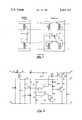
- FIG. 1is a schematic diagram illustrating one prior art technique for providing DC power feed current to repeaters by means of a simplex power loop.
- FIG. 2is a schematic diagram of one embodiment of this invention.
- DC power feed currentis supplied from a central office 2 via signal line (transmission cable pair) 12 to repeater 14.
- the repeater voltage supply developed at terminals 21 and 23is symbolically shown to be obtained from zener diode 20, or a result of the DC power feed current fed through the simplex power loop. It is apparent that at a more distant repeater a power connection would be made between signal line 12 and signal line 13 to provide the necessary return path to the power supply 8 at central office 2. It also is apparent that one signal line could be used, such as 12 in FIG. 1, and the return path could be an earth ground. In any case, the signal line may be and often is exposed to the elements so that longitudinally induced currents are caused by lightning.
- a power regulatorsuch as is shown in FIG. 2 replaces zener diode 20 and is connected between the voltage supply terminals 21 and 23 and the repeater power input circuit to minimize the effect of these induced currents.
- FIG. 2interconnects between a signal line repeater and the signal line.
- a pair of input terminals 40 and 42connect to the signal line terminals 21 and 23 to receive an input current, i.e., the line current which energizes the signal repeater.
- Input terminals 40 and 42connect to the signal line such that the polarity of terminal 40 is positive with respect to terminal 42.
- Output terminals 44 and 46connect to the power input connections of the signal repeater (not shown) with terminal 44 being positive with respect to terminal 46.
- terminals 42 and 46are common with each other.
- Diode CR1connected across terminals 40 and 42 protects against large currents
- diode CR2connected between lead 50 and lead 52 in combination with diode CR1 protect against reverse current.
- Inductor L1which offers an AC impedance to the line is connected across lead 52 and an output lead 54 which eventually connects to terminal 44.
- CR2 and L1conducts the DC input current to a shunt voltage regulating means which includes zener diode CR4 which serves as a reference source for shunt current regulator comparator 63.
- Resistor R1provides necessary current to assure proper zener operation of CR4.
- Resistors R2, R3, and R4provide the first and second bias voltage inputs to comparators 61 and 63.
- Capacitors C1, C2, and C3provide a low impedance for by-passing spurious currents which may affect the reference voltage developed by CR4.
- Shunt current regulator comparator 63is connected to the current limited compound shunt regulator consisting of Q1, R5, CR6, CR7, R6, R8 and Q2.
- L1is the input stage of the shunt current regulator.
- R5limits the current through Q1 and CR6 and CR7 to approximately 200 milliamperes.
- R6assures that Q2 will turn off when no current flows through Q1.
- Diodes CR6 and CR7limit the voltage between output terminal 44 and the base of Q2 to approximately 1.8 V. This will limit the voltage across R8 to approximately 0.9 V and thereby limit the current through R8 and Q2 to 9.0 amperes, thereby preventing self destruction of R8 and Q2.
- the total shunt current regulator capabilityis thereby approximately 9.2 amperes. (Sum of Q1 current and Q2 current).
- CR4has a zener voltage of 4.5 V and results in a voltage of approximately 10 V across output terminals 44 and 46.
- the shunt current regulatorwill therefore maintain the voltage across terminals 44 and 46 at approximately 10 V when the input current varies from the minimum bias current of approximately 100 mA to a current of 9.2 amperes.
- Comparator 61, CR5, Q3, CR3 and C4form an energy storage and control means.
- Diode CR3conducts current when the voltage at the junction of CR2, L1 and CR3 exceeds the voltage across C4 by 0.6 V (assumes CR3 is silicon device) and will charge C4 to a voltage of 0.6 V less than at the junction of CR2, CR3 and L1.
- the voltage at output terminal 44is approximately 1.0 V less than that at the junction of CR2, CR3 and L1 due to the DC resistance of L1 ( ⁇ 10 ⁇ ) and the minimum bias current required for the repeater and control circuitry of 100 mA. This results in the voltage at terminal 48 being approximately 0.4 V higher than the normal voltage at output terminal 44.
- Diode CR1serves to protect the circuitry from potential damage from very large currents (i.e., greater than 9.2 amperes) and CR1 and CR2 protect circuitry from reverse currents.
- the input currententers at terminal 40, and is conducted through diode CR2 and inductor L1. A small portion of this current goes to bias the voltage reference source CR4 via resistor R1, an additional small portion is conducted through the comparator input bias network R2, R3 and R4, and the remainder is connected through to the output terminals and the repeater load.
Landscapes
- Engineering & Computer Science (AREA)
- Computer Networks & Wireless Communication (AREA)
- Signal Processing (AREA)
- Emergency Protection Circuit Devices (AREA)
- Devices For Supply Of Signal Current (AREA)
Abstract
Description
Claims (5)
Priority Applications (2)
| Application Number | Priority Date | Filing Date | Title |
|---|---|---|---|
| US05/965,974US4241243A (en) | 1978-12-04 | 1978-12-04 | Power regulator for use with line signal repeaters which are remotely powered |
| CA340,857ACA1133047A (en) | 1978-12-04 | 1979-11-29 | Protection circuit for controlling the effect of induced current on line signal repeaters |
Applications Claiming Priority (1)
| Application Number | Priority Date | Filing Date | Title |
|---|---|---|---|
| US05/965,974US4241243A (en) | 1978-12-04 | 1978-12-04 | Power regulator for use with line signal repeaters which are remotely powered |
Publications (1)
| Publication Number | Publication Date |
|---|---|
| US4241243Atrue US4241243A (en) | 1980-12-23 |
Family
ID=25510758
Family Applications (1)
| Application Number | Title | Priority Date | Filing Date |
|---|---|---|---|
| US05/965,974Expired - LifetimeUS4241243A (en) | 1978-12-04 | 1978-12-04 | Power regulator for use with line signal repeaters which are remotely powered |
Country Status (2)
| Country | Link |
|---|---|
| US (1) | US4241243A (en) |
| CA (1) | CA1133047A (en) |
Cited By (12)
| Publication number | Priority date | Publication date | Assignee | Title |
|---|---|---|---|---|
| EP0124030A1 (en)* | 1983-04-28 | 1984-11-07 | Siemens Aktiengesellschaft | Power supply for series fed electronic circuits |
| US5270904A (en)* | 1990-05-02 | 1993-12-14 | Zdzislaw Gulczynski | Switching power apparatus with 3-state driver |
| US6175556B1 (en)* | 1994-06-06 | 2001-01-16 | International Business Machines Corporation | Remote powered ethernet repeater |
| ES2167210A1 (en)* | 2000-02-18 | 2002-05-01 | Telefonica Sa | Protection equipment for pulse code modulation installations |
| RU2242831C2 (en)* | 2003-02-10 | 2004-12-20 | Открытое акционерное общество "Ракетно-космическая корпорация "Энергия" имени С.П. Королева" | Voltage switching device incorporating load unit overcurrent protective gear |
| RU2280292C1 (en)* | 2004-12-15 | 2006-07-20 | Фгуп "Нии Сиис" | Method for load protection against abnormal supply voltage |
| US7317793B2 (en) | 2003-01-30 | 2008-01-08 | Serconet Ltd | Method and system for providing DC power on local telephone lines |
| US7424031B2 (en) | 1998-07-28 | 2008-09-09 | Serconet, Ltd. | Local area network of serial intelligent cells |
| US7483524B2 (en) | 1999-07-20 | 2009-01-27 | Serconet, Ltd | Network for telephony and data communication |
| US7522714B2 (en) | 2000-03-20 | 2009-04-21 | Serconet Ltd. | Telephone outlet for implementing a local area network over telephone lines and a local area network using such outlets |
| US8582598B2 (en) | 1999-07-07 | 2013-11-12 | Mosaid Technologies Incorporated | Local area network for distributing data communication, sensing and control signals |
| US10986164B2 (en) | 2004-01-13 | 2021-04-20 | May Patents Ltd. | Information device |
Citations (4)
| Publication number | Priority date | Publication date | Assignee | Title |
|---|---|---|---|---|
| US3986078A (en)* | 1974-05-10 | 1976-10-12 | Tekade Felten & Guilleaume Fernmeldeanlagen Gmbh | Devices for limiting the output voltage of current-controlled remote feed apparatuses |
| US4049929A (en)* | 1976-12-16 | 1977-09-20 | Gte Lenkurt Electric (Canada) Ltd. | Apparatus for reducing the susceptibility of line signal repeaters to induced currents |
| US4099217A (en)* | 1976-02-18 | 1978-07-04 | The Post Office | Protection circuits |
| US4110570A (en)* | 1976-05-25 | 1978-08-29 | International Standard Electric Corporation | Surge protection device for repeater |
- 1978
- 1978-12-04USUS05/965,974patent/US4241243A/ennot_activeExpired - Lifetime
- 1979
- 1979-11-29CACA340,857Apatent/CA1133047A/ennot_activeExpired
Patent Citations (4)
| Publication number | Priority date | Publication date | Assignee | Title |
|---|---|---|---|---|
| US3986078A (en)* | 1974-05-10 | 1976-10-12 | Tekade Felten & Guilleaume Fernmeldeanlagen Gmbh | Devices for limiting the output voltage of current-controlled remote feed apparatuses |
| US4099217A (en)* | 1976-02-18 | 1978-07-04 | The Post Office | Protection circuits |
| US4110570A (en)* | 1976-05-25 | 1978-08-29 | International Standard Electric Corporation | Surge protection device for repeater |
| US4049929A (en)* | 1976-12-16 | 1977-09-20 | Gte Lenkurt Electric (Canada) Ltd. | Apparatus for reducing the susceptibility of line signal repeaters to induced currents |
Cited By (37)
| Publication number | Priority date | Publication date | Assignee | Title |
|---|---|---|---|---|
| EP0124030A1 (en)* | 1983-04-28 | 1984-11-07 | Siemens Aktiengesellschaft | Power supply for series fed electronic circuits |
| US5270904A (en)* | 1990-05-02 | 1993-12-14 | Zdzislaw Gulczynski | Switching power apparatus with 3-state driver |
| US6175556B1 (en)* | 1994-06-06 | 2001-01-16 | International Business Machines Corporation | Remote powered ethernet repeater |
| US7653015B2 (en) | 1998-07-28 | 2010-01-26 | Mosaid Technologies Incorporated | Local area network of serial intelligent cells |
| US8325636B2 (en) | 1998-07-28 | 2012-12-04 | Mosaid Technologies Incorporated | Local area network of serial intelligent cells |
| US8885659B2 (en) | 1998-07-28 | 2014-11-11 | Conversant Intellectual Property Management Incorporated | Local area network of serial intelligent cells |
| US8867523B2 (en) | 1998-07-28 | 2014-10-21 | Conversant Intellectual Property Management Incorporated | Local area network of serial intelligent cells |
| US7424031B2 (en) | 1998-07-28 | 2008-09-09 | Serconet, Ltd. | Local area network of serial intelligent cells |
| US7965735B2 (en) | 1998-07-28 | 2011-06-21 | Mosaid Technologies Incorporated | Local area network of serial intelligent cells |
| US8908673B2 (en) | 1998-07-28 | 2014-12-09 | Conversant Intellectual Property Management Incorporated | Local area network of serial intelligent cells |
| US8885660B2 (en) | 1998-07-28 | 2014-11-11 | Conversant Intellectual Property Management Incorporated | Local area network of serial intelligent cells |
| US8270430B2 (en) | 1998-07-28 | 2012-09-18 | Mosaid Technologies Incorporated | Local area network of serial intelligent cells |
| US7969917B2 (en) | 1998-07-28 | 2011-06-28 | Mosaid Technologies Incorporated | Local area network of serial intelligent cells |
| US7986708B2 (en) | 1998-07-28 | 2011-07-26 | Mosaid Technologies Incorporated | Local area network of serial intelligent cells |
| US7978726B2 (en) | 1998-07-28 | 2011-07-12 | Mosaid Technologies Incorporated | Local area network of serial intelligent cells |
| US7830858B2 (en) | 1998-07-28 | 2010-11-09 | Mosaid Technologies Incorporated | Local area network of serial intelligent cells |
| US7852874B2 (en) | 1998-07-28 | 2010-12-14 | Mosaid Technologies Incorporated | Local area network of serial intelligent cells |
| US8582598B2 (en) | 1999-07-07 | 2013-11-12 | Mosaid Technologies Incorporated | Local area network for distributing data communication, sensing and control signals |
| US7492875B2 (en) | 1999-07-20 | 2009-02-17 | Serconet, Ltd. | Network for telephony and data communication |
| US8929523B2 (en) | 1999-07-20 | 2015-01-06 | Conversant Intellectual Property Management Inc. | Network for telephony and data communication |
| US7522713B2 (en) | 1999-07-20 | 2009-04-21 | Serconet, Ltd. | Network for telephony and data communication |
| US8351582B2 (en) | 1999-07-20 | 2013-01-08 | Mosaid Technologies Incorporated | Network for telephony and data communication |
| US7483524B2 (en) | 1999-07-20 | 2009-01-27 | Serconet, Ltd | Network for telephony and data communication |
| ES2167210A1 (en)* | 2000-02-18 | 2002-05-01 | Telefonica Sa | Protection equipment for pulse code modulation installations |
| US8855277B2 (en) | 2000-03-20 | 2014-10-07 | Conversant Intellectual Property Managment Incorporated | Telephone outlet for implementing a local area network over telephone lines and a local area network using such outlets |
| US7522714B2 (en) | 2000-03-20 | 2009-04-21 | Serconet Ltd. | Telephone outlet for implementing a local area network over telephone lines and a local area network using such outlets |
| US8363797B2 (en) | 2000-03-20 | 2013-01-29 | Mosaid Technologies Incorporated | Telephone outlet for implementing a local area network over telephone lines and a local area network using such outlets |
| US7715534B2 (en) | 2000-03-20 | 2010-05-11 | Mosaid Technologies Incorporated | Telephone outlet for implementing a local area network over telephone lines and a local area network using such outlets |
| US8787562B2 (en) | 2003-01-30 | 2014-07-22 | Conversant Intellectual Property Management Inc. | Method and system for providing DC power on local telephone lines |
| US7317793B2 (en) | 2003-01-30 | 2008-01-08 | Serconet Ltd | Method and system for providing DC power on local telephone lines |
| US8107618B2 (en) | 2003-01-30 | 2012-01-31 | Mosaid Technologies Incorporated | Method and system for providing DC power on local telephone lines |
| US7702095B2 (en) | 2003-01-30 | 2010-04-20 | Mosaid Technologies Incorporated | Method and system for providing DC power on local telephone lines |
| RU2242831C2 (en)* | 2003-02-10 | 2004-12-20 | Открытое акционерное общество "Ракетно-космическая корпорация "Энергия" имени С.П. Королева" | Voltage switching device incorporating load unit overcurrent protective gear |
| US10986164B2 (en) | 2004-01-13 | 2021-04-20 | May Patents Ltd. | Information device |
| US11032353B2 (en) | 2004-01-13 | 2021-06-08 | May Patents Ltd. | Information device |
| US11095708B2 (en) | 2004-01-13 | 2021-08-17 | May Patents Ltd. | Information device |
| RU2280292C1 (en)* | 2004-12-15 | 2006-07-20 | Фгуп "Нии Сиис" | Method for load protection against abnormal supply voltage |
Also Published As
| Publication number | Publication date |
|---|---|
| CA1133047A (en) | 1982-10-05 |
Similar Documents
| Publication | Publication Date | Title |
|---|---|---|
| US4241243A (en) | Power regulator for use with line signal repeaters which are remotely powered | |
| US4254442A (en) | Circuit for the protection of telephone lines | |
| US5574632A (en) | Power supply comprising a circuit for limiting inrush currents | |
| CA2026789C (en) | Power feed circuit for digital communications terminal equipment | |
| EP0450884B1 (en) | A subscriber line interface circuit providing regulated current | |
| US4322586A (en) | Transformerless line interface circuit | |
| US4056689A (en) | Telephone subscriber line circuit | |
| US5708574A (en) | Adaptive power direct current preregulator | |
| US4394703A (en) | Load protecting arrangement | |
| US4803721A (en) | DC control circuit | |
| AU603587B2 (en) | Transient protection device | |
| US4803722A (en) | Circuit for remote supply of subscriber line terminals in a telecommunication system | |
| US4555660A (en) | Current supply device for series-fed electronic circuits | |
| EP0661864A1 (en) | Battery feed for telephone line cards | |
| EP0232317B1 (en) | Apparatus for providing a ground reference for telephone customer special circuits powered from a floating battery feed | |
| US4571460A (en) | Active impedance line feed circuit with improved ground fault protection | |
| US4761812A (en) | Constant power telephone line circuit | |
| EP0425675B1 (en) | Ground fault detecting circuit for subscriber lines | |
| US4423292A (en) | Detector circuit for communication lines | |
| US4049929A (en) | Apparatus for reducing the susceptibility of line signal repeaters to induced currents | |
| US3435294A (en) | Voltage regulator circuit having constant input impedance and means for protecting against load voltage ripple | |
| CA1139470A (en) | Transformerless line interface circuit | |
| US4562525A (en) | DC Power supply circuit for line interface circuits | |
| US3707684A (en) | Error amplifier for switching regulator | |
| EP0155074B1 (en) | Active impedance line feed circuit with improved ground fault protection |
Legal Events
| Date | Code | Title | Description |
|---|---|---|---|
| AS | Assignment | Owner name:148074 HOLDINGS CANADA LTD., Free format text:CHANGE OF NAME;ASSIGNOR:MICROTEL LIMITED;REEL/FRAME:004890/0935 Effective date:19851231 Owner name:AEL MICROTEL LIMITED Free format text:CHANGE OF NAME;ASSIGNOR:GTE AUTOMATIC ELECTRIC (CANADA) LTD.,;REEL/FRAME:004890/0863 Effective date:19860411 Owner name:147170 CANADA HOLDINGS LTD., Free format text:ASSIGNMENT OF ASSIGNORS INTEREST.;ASSIGNOR:MICROTEL LIMITED;REEL/FRAME:004890/0924 Effective date:19851231 Owner name:MICROTEL LIMITED-MICROTEL LIMITEE Free format text:CHANGE OF NAME;ASSIGNOR:AEL MICROTEL LIMITED-AEL MICROTEL LIMITED;REEL/FRAME:004890/0901 Effective date:19860710 Owner name:MICROTEL LIMITED-MICROTEL LIMITEE Free format text:CHANGE OF NAME;ASSIGNOR:147170 CANADA HOLDINGS LTD.;REEL/FRAME:005811/0405 Effective date:19860710 Owner name:147170 CANADA HOLDINGS LTD. Free format text:ASSIGNMENT OF ASSIGNORS INTEREST.;ASSIGNOR:MICROTEL LIMITED;REEL/FRAME:005811/0392 Effective date:19851231 Owner name:AEL MICROTEL LIMITED Free format text:CERTIFICATE OF AMALGAMATION, EFFECTIVE OCT. 27, 1979.;ASSIGNORS:AEL MICROTEL LIMITED;GTE LENKURT ELECTRIC (CANADA) LTD.;REEL/FRAME:005811/0377 Effective date:19860710 Owner name:AEL MICROTEL LIMITED - AEL MICROTEL LIMITEE Free format text:CHANGE OF NAME;ASSIGNOR:AEL MICROTEL LIMITED;REEL/FRAME:004890/0889 Effective date:19860710 |