US4239092A - Adjustable tensioner - Google Patents
Adjustable tensionerDownload PDFInfo
- Publication number
- US4239092A US4239092AUS05/937,069US93706978AUS4239092AUS 4239092 AUS4239092 AUS 4239092AUS 93706978 AUS93706978 AUS 93706978AUS 4239092 AUS4239092 AUS 4239092A
- Authority
- US
- United States
- Prior art keywords
- magnetic
- outer housing
- magnetic assembly
- assembly
- space
- Prior art date
- Legal status (The legal status is an assumption and is not a legal conclusion. Google has not performed a legal analysis and makes no representation as to the accuracy of the status listed.)
- Expired - Lifetime
Links
Images
Classifications
- F—MECHANICAL ENGINEERING; LIGHTING; HEATING; WEAPONS; BLASTING
- F16—ENGINEERING ELEMENTS AND UNITS; GENERAL MEASURES FOR PRODUCING AND MAINTAINING EFFECTIVE FUNCTIONING OF MACHINES OR INSTALLATIONS; THERMAL INSULATION IN GENERAL
- F16D—COUPLINGS FOR TRANSMITTING ROTATION; CLUTCHES; BRAKES
- F16D37/00—Clutches in which the drive is transmitted through a medium consisting of small particles, e.g. centrifugally speed-responsive
- F16D37/02—Clutches in which the drive is transmitted through a medium consisting of small particles, e.g. centrifugally speed-responsive the particles being magnetisable
- F—MECHANICAL ENGINEERING; LIGHTING; HEATING; WEAPONS; BLASTING
- F16—ENGINEERING ELEMENTS AND UNITS; GENERAL MEASURES FOR PRODUCING AND MAINTAINING EFFECTIVE FUNCTIONING OF MACHINES OR INSTALLATIONS; THERMAL INSULATION IN GENERAL
- F16D—COUPLINGS FOR TRANSMITTING ROTATION; CLUTCHES; BRAKES
- F16D27/00—Magnetically- or electrically- actuated clutches; Control or electric circuits therefor
- F16D27/01—Magnetically- or electrically- actuated clutches; Control or electric circuits therefor with permanent magnets
- F—MECHANICAL ENGINEERING; LIGHTING; HEATING; WEAPONS; BLASTING
- F16—ENGINEERING ELEMENTS AND UNITS; GENERAL MEASURES FOR PRODUCING AND MAINTAINING EFFECTIVE FUNCTIONING OF MACHINES OR INSTALLATIONS; THERMAL INSULATION IN GENERAL
- F16D—COUPLINGS FOR TRANSMITTING ROTATION; CLUTCHES; BRAKES
- F16D37/00—Clutches in which the drive is transmitted through a medium consisting of small particles, e.g. centrifugally speed-responsive
- F16D2037/007—Clutches in which the drive is transmitted through a medium consisting of small particles, e.g. centrifugally speed-responsive characterised by multiple substantially radial gaps in which the fluid or medium consisting of small particles is arranged
Definitions
- This inventionpertains to a tensioning device or slip clutch.
- the inventionrelates to a tensioning device utilizing a permanent magnet and a magnetic coupling provided by magnetic particles to obtain an adjustable torque slip clutch.
- Tensioners or slip clutcheshave been used for a number of years in industrial uses.
- One function of these tensioners or clutchesis to provide a certain level of torque or resistance to turning in machinery where material is being wound or unwound on a mandril.
- friction clutcheshave been frequently used to provide the desired resistance to turning.
- friction clutcheshave a disadvantage because the friction material slips or abrades and gradually wears out.
- the life of the friction clutchcan be fairly short and is dependent upon the level of abrasion produced as the friction surfaces slip over one another.
- Another factor that limits the usefulness of this type of clutch arrangementis that as the friction surfaces wear the surfaces often do not provide the same amount of torque or resistance to turning.
- the torque or resistance to turningcan vary in the friction clutch due to the amount of wear received by the friction surfaces of the clutch.
- Another difficultyis that a powdery material can be produced as the friction surfaces wear. The powder is usually contained within the friction clutch mechanism and frequently causes difficulty with the operation of the friction clutch.
- An electrically magnetized coilcan be used to provide the desired resistance to turning. However, it is frequently difficult to provide the electrically wiring and power required to energize the magnetizable coil. The difficulties associated with an electrially magnetized coil are further compounded in areas where electrical power is not readily available or where power outages occur during the operation of the coil. Clearly such difficulties render the electrically magnetized coil virtually useless as a tensioning device or slip clutch.
- a permanent magnet and the magnetic flux from the magnetcan be used to link two coupling elements to provide the desired resistance to turning.
- the difficulty with using a permanent magnetis that it is very difficult to adjust the magnetic flux of the magnet to vary the torque or resistance to turning produced by the magnet.
- flux gatesas shown in U.S. Pat. No. 3,822,290, have been used to vary the magnetic flux produced by the permanent magnet.
- flux gateshave the disadvantage in that they reduce the maximum torque capability for a given size magnet.
- a flux gateis used as the means for varying the output torque of the magnet.
- An adjustable magnetic shuntcan also be positioned at the center of the magnet as a means for adjusting the flux of the magnet.
- the large size of the magnetic shuntadversely effects the relationship between the torque output and the size of the tensioning device.
- the use of a magnetic shunthas the disadvantage of inherently increasing the size of the tensioner to provide the desired range of torque or resistance to turning.
- a magnetic tensioning devicecomprising a rotatable outer housing and a magnetic assembly positioned in the interior of the outer housing.
- a spaceis provided between the outer housing and the magnetic assembly.
- a plurality of magnetic particlesis positioned in the space between the magnetic assembly and the outer housing. The magnetic particles are held in place by the magnetic flux from the magnetic assembly and the magnetic particles magnetically couple the magnetic assembly and the outer housing.
- Means for varying the size of the space between the magnetic assembly and the outer housingis provided. The varying of the size of the space varies the magnetic flux from the magnetic assembly and changes the magnetic coupling between the magnetic assembly and the outer housing.
- FIG. 1is a perspective view of the tensioning device.
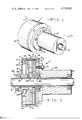
- FIG. 2is a cross sectional view of the tensioning device taken along line 2--2 and shown adjusted for a minimum torque transfer.
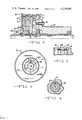
- FIG. 3is an end elevation view of the tensioning device.
- FIG. 4is a partial cross sectional view of the tensioning device taken along line 4--4 of FIG. 2.
- FIG. 5is a partial cross sectional view of the tensioning device and shown adjusted for a maximum torque transfer.
- FIG. 6is a partial cross sectional view of another embodiment of the tensioning device.
- FIGS. 1, 2, 3 and 4shows a tensioning device 1 that is comprised of an outer housing 3 that is generally cylindrical in shape.
- the outer housingis usually constructed from magnetizable metal such as cold rolled steel tubing.
- a substantially cylindrical magnetic assembly 5is positioned in the interior of the outer housing.
- the magnetic assemblycontains a permanent magnet 7, such as a ceramic magnet. Structurally bonded to the magnet is a first magnetically soft plate 9 and a second magnetically soft plate 11.
- the permanent magnet and the platesare magnetized as an assembly so that one face of the magnet (labeled N) is a north pole and the other face (labeled S) a south pole.
- the two magnetically soft platesact as flux collectors and concentrate the magnetic flux that is produced by the permanent magnet.
- the lines of magnetic flux, produced by the permanent magnetare shown as lines 12.
- the two magnetically soft platesare usually constructed of a material such as steel and, accordingly, the plates are magnetically soft but not necessarily mechanically soft.
- the radial grooves 13are spaced substantially the same distance apart as the two magnetically soft plates 9 and 11 on the magnetic assembly.
- the widths of the two radial groovesare substantially the same as the widths of the magnetically soft plates. As shown in FIG. 2 the position of the two magnetically soft plates corresponds generally with the position of the two radial grooves 13 in the outer housing.
- An annular space 14is located between the outer peripheral surface of the magnetic assembly 5 and the inner peripheral surface of the outer housing 3.
- the space 14is usually between from about 0.020" to about 0.050" in size although the space can be almost any size to accomodate different torque requirements for the tensioning device. It should also be noted that the space between the magnetic assembly and the outer housing will increase in the area of the two radial grooves 13.
- a plurality of magnetic particles 16Positioned in the space between the magnetic assembly and the outer housing are a plurality of magnetic particles 16.
- the magnetic particlesare attracted by the magnetic flux from the permanent magnet 7.
- the two magnetically soft plates 9 and 11concentrate the magnetic flux and pass the flux through the outer periphery of the soft plates. Accordingly, the magnetic particles are concentrated in the annular space 14 near the outer peripheral edge of the plates.
- a stationary, shaft 15passes through the center of the adjustable tensioner.
- a spindle shaft 18, having an axial keyway 17is positioned on a portion of the shaft 15.
- Spindle shaft 18is preferably a non-magnetic material, such as 300 series stainless steel, to provide a high reluctance path that minimizes magnetic flux leakage through the inside diameter of the permanent magnet 7.
- Shaft 15can be a magnetizable metal since spindle shaft 18 minimizes flux leakage from the permanent magnet.
- the spindle shaftis positioned in non-rotatable relationship on the shaft 15 by securement means 20.
- the first soft plate 9extends into the axial keyway 17 and the position of the first soft plate in the keyway prevents the magnetic assembly from rotating relative to the shaft 15. However, the first soft plate 9 is free to move in an axial direction along the keyway 17. Accordingly, the magnetic assembly is also free to move in an axial direction relative to the shaft 15.
- An adjustment mechanism 21is rotatably positioned on the spindle shaft 18.
- a snap ring 24is positioned in a groove on the spindle shaft 18 in contact with one end of the adjustment mechanism.
- the other end of the adjustment mechanismis in contact with a shoulder 25 that is located on the spindle shaft 18 where the axial keyway 17 terminates.
- the snap ring 24 and shoulder 25act to restrain the adjustment mechanism 21 from axial movement along the shaft 15 while allowing the adjustment mechanism to rotate freely around the shaft 15.
- the adjustment mechanismhas a plurality of threads 22 positioned on one surface. Threads 23, that are mateable with threads 22 on the adjustment mechanism, are positioned on the inner peripheral edge of the second magnetically soft plate 11.
- the second magnetically soft plate 11 and the adjustment mechanism 21are positioned with respect to one another so that the threads 22 and 23 are in engaging relationship.
- a rotatable chuck 27is mounted on the shaft 15. Suitable bearings 29 are positioned on the stationary shaft 15 so that the chuck 27 is free to rotate relative to the shaft. Bolts 31 or other suitable fastening means are used to secure one end of the rotatable chuck to the outer housing 3.
- the outer housing 3is also positioned on bearings 29 and is free to rotate relative to the shaft 15.
- the rotatable chuckis attached to the outer housing in such a manner that the housing rotates when the chuck is caused to rotate.
- FIG. 5shows the magnetic assembly 5 in another position with respect to the outer housing 3.
- the magnetic assemblyhas moved axially along the shaft 15 and plate 9 has moved axially along keyway 17.
- the threads 23 on the plate 11have also moved axially along the threads 22 on the adjustment mechanism 21.
- the two magnetically soft platesare no longer in alignment with the two radial grooves 13 in the outer housing 3.
- the space 14 between the two magnetically soft plates and the outer housingwill be considerably less than the space when the two plates are in alignment with the radial grooves.
- the magnetic flux from the north pole of the magnet 7passes into the second soft plate 11 where the flux is concentrated and directed so that the flux passes through the outer peripheral edge of the second plate.
- the magnetic fluxthen passes through the space 14 positioned between the magnetic assembly and the outer housing 3.
- the magnetic fluxpasses through the material of the outer housing, back across the space 14 and into the outer peripheral edge of the first soft plate 9.
- the second soft platedirects this flux to the south magnetic pole of the permanent magnet 7.
- the magnetic particles 16will be attracted by this magnetic flux. Accordingly, the magnetic particles are concentrated at the outer peripheral edges of the two soft plates.
- the magnetic particles 16are attracted to these lines of flux and form chains or columns of magnetic particles across the space between the outer peripheral edges of the two plates and the outer housing.
- These chains of magnetic particlesform a magnetic coupling between the magnetic assembly and the outer housing of the tensioning device.
- the magnetic particlesform a magnetic connection or bond between the magnetic assembly and the outer housing.
- the strength of the chains or columns formed by the magnetic particlesis dependent upon the strength of the magnetic flux passing across the space 14 between the magnetic assembly and the outer housing.
- the strength of the lines of fluxwill be dependent upon the strength of the permanent magnet, the degree of collection and concentration of the flux by the two magnetically soft plates, the size of the space 14 between the magnetic assembly and the outer housing, and the material of which the outer housing is formed. It should be noted that the larger the space 14 between the magnetic assembly and the outer housing, the weaker the lines of flux bridging this space will be.
- the two soft magnetic platesare positioned so that they are in substantial alignment with the two radial grooves 13 in the outer housing 3.
- the lines of magnetic fluxbridging across the space 14 between the outer peripheral edges of the plates and the outer housing, will have to pass through the additional air space created by the two radial grooves. This reduces the strength of the magnetic flux bridging across this space and, accordingly, reduces the strength of the chains or columns of magnetic particles formed along the lines of magnetic flux.
- the connection or torque transfer between the magnetic assembly 5 and the outer housing 3would be at its lowest point.
- the magnetic assemblyTo increase the connection or coupling between the magnetic assembly and the outer housing 3 the magnetic assembly must be moved or shifted axially so that the two magnetically soft plates are no longer in complete alignment with the two radial grooves 13.
- the moving of the magnetic assemblycan be accomplished by causing the adjustment mechanism 21 to rotate.
- the rotation of the adjustment mechanism 21causes the threads 23 on the inner peripheral edge of the second plate 11 to advance along the threads 22 located on the adjustment mechanism 21.
- the rotation of the adjustment mechanism 21causes the second plate 11 to move axially along the threads 22 away from the chuck 27. It should be noted, that as the second plate 11 moves, the entire magnetic assembly 5 will also move with the second plate.
- the magnetic assembly 5Since the first plate 9 is positioned in axial keyway 17 located on spindle shaft 18 the magnetic assembly 5 will be free to move in an axial direction along the shaft 15. However, the positioning of the first plate 9 in the axial keyway 17 will prevent the magnetic assembly 5 from moving in a radial direction with respect to shaft 15 or the outer housing 3. The movement of the magnetic assembly 5 causes the two plates to move out of alignment with the two radial grooves 13. As the two plates move out of alignment with the radial grooves 13 the air gap between the outer peripheral edge of the two plates and the outer housing 3 will be reduced and the strength of the lines of magnetic flux bridging the space 14 will be increased.
- the adjustment mechanism 21can be rotated to reposition the magnetic assembly 5 with respect to the radial grooves 13 until the desired amount of tension is supplied to resist the rotation of the chuck 27.
- FIG.6shows another embodiment that can be used in the tensioning device.
- the outer housing 3is adapted with radial grooves 13 and a non-magnetic insert 35 has been positioned in the radial grooves.
- the magnetic flux flowing from the outer peripheral edge of the plateswill pass through the non-magnetic inserts 35 located in the two radial grooves 13.
- the non-magnetic material in the insertswill act as a poor conductor of the magnetic flux and will result in a reduction in the force of the magnetic flux passing from the outer peripheral edge of the plates into the outer housing.
- the non-magnetic material of the insertswill result in a decrease in the strength of the magnetic flux that is greater than the decrease that is present when the magnetic flux passes through an air gap.
- the magnetic particles 16 located in the space 14 between the outer peripheral edge of the magnetic assembly 5 and the outer housing 3will be subjected to a lower magnetic flux. Accordingly, the magnetic particles 16 will form chains or columns across the space 14 that are not as strong as the columns that are formed when the non-magnetic inserts 35 are not present in the radial grooves 13.
- the magnetic coupling between the magnetic assembly 5 and the outer housing 3, created by the magnetic particles 16,will be decreased.
- the resistance to turning of the outer housing 3 and the chuck 27, that is connected to the outer housing,will be reduced.
- the non-magnetic inserts 35will act to reduce the magnetic coupling between the outer housing 3 and magnetic assembly 5 until the two plates are moved to a position where they are completely out of alignment with the non-magnetic inserts 35 located in the outer housing.
- the non-magnetic inserts 35will act to lower the magnetic coupling between the magnetic assembly 5 and the outer housing 3 when the magnetic assembly is in the position where there is the least amount of magnetic coupling.
- the non-magnetic insertsreduce the resistance to rotation of the tensioning device at the lower end of the tension range when the two magnetically soft plates are at least partially in alignment with the non-magnetic inserts 35.
Landscapes
- Engineering & Computer Science (AREA)
- General Engineering & Computer Science (AREA)
- Mechanical Engineering (AREA)
- Braking Arrangements (AREA)
- Devices For Conveying Motion By Means Of Endless Flexible Members (AREA)
Abstract
Description
Claims (8)
Priority Applications (4)
| Application Number | Priority Date | Filing Date | Title |
|---|---|---|---|
| US05/937,069US4239092A (en) | 1978-08-28 | 1978-08-28 | Adjustable tensioner |
| DE19792931261DE2931261A1 (en) | 1978-08-28 | 1979-08-01 | MAGNETIC SLIP CLUTCH, ESPECIALLY IN THE FORM OF A DEVICE MONITORING THE UNWINDING OR REWINDING TENSION |
| GB7929358AGB2029126B (en) | 1978-08-28 | 1979-08-23 | Adjustable magnetic coupling |
| JP10734279AJPS5533986A (en) | 1978-08-28 | 1979-08-24 | Magnetism type tension force adding device |
Applications Claiming Priority (1)
| Application Number | Priority Date | Filing Date | Title |
|---|---|---|---|
| US05/937,069US4239092A (en) | 1978-08-28 | 1978-08-28 | Adjustable tensioner |
Publications (1)
| Publication Number | Publication Date |
|---|---|
| US4239092Atrue US4239092A (en) | 1980-12-16 |
Family
ID=25469448
Family Applications (1)
| Application Number | Title | Priority Date | Filing Date |
|---|---|---|---|
| US05/937,069Expired - LifetimeUS4239092A (en) | 1978-08-28 | 1978-08-28 | Adjustable tensioner |
Country Status (4)
| Country | Link |
|---|---|
| US (1) | US4239092A (en) |
| JP (1) | JPS5533986A (en) |
| DE (1) | DE2931261A1 (en) |
| GB (1) | GB2029126B (en) |
Cited By (42)
| Publication number | Priority date | Publication date | Assignee | Title |
|---|---|---|---|---|
| US4529196A (en)* | 1983-02-25 | 1985-07-16 | Logan Robert C | Exercise device |
| US4674741A (en)* | 1985-08-05 | 1987-06-23 | Bally Manufacturing Corporation | Rowing machine with video display |
| US4718303A (en)* | 1986-10-06 | 1988-01-12 | Borg-Warner Automotive, Inc. | Four wheel drive transfer case with clutch mechanism |
| US4844220A (en)* | 1986-02-26 | 1989-07-04 | Shinko Electric Co., Ltd. | Torque limiter |
| US4856631A (en)* | 1987-07-24 | 1989-08-15 | Mitsubishi Denki Kabushiki Kaisha | Permanent magnet coupling torque limiter |
| US4878429A (en)* | 1988-05-26 | 1989-11-07 | Nu-Graphics Engineering, Inc. | Magnetic rotary locking mechanism and method |
| US4974512A (en)* | 1988-05-26 | 1990-12-04 | Nu-Graphics Equipment, Inc. | Magnetic rotary locking and tensioning mechanism |
| US5090531A (en)* | 1990-01-10 | 1992-02-25 | Lord Corporation | Electrophoretic fluid differential |
| US5158279A (en)* | 1991-09-30 | 1992-10-27 | Xerox Corporation | Magnetic clutch with adjustable slip torque |
| US5598908A (en)* | 1995-06-05 | 1997-02-04 | Gse, Inc. | Magnetorheological fluid coupling device and torque load simulator system |
| US6027429A (en)* | 1993-11-03 | 2000-02-22 | Nordictrack, Inc. | Variable resistance exercise device |
| US6466119B1 (en) | 1996-09-06 | 2002-10-15 | Chester Drew | Magnetic circuit |
| US20040074718A1 (en)* | 2002-03-19 | 2004-04-22 | Hiroshi Takeda | Simplified loading device |
| US6762523B1 (en)* | 1999-08-11 | 2004-07-13 | The Swatch Group Management Services Ag | Continuously variable electromagnetic transmission |
| US6823971B2 (en)* | 2000-10-20 | 2004-11-30 | Oriental Motor Co., Inc. | Simplified loading device |
| US20050247136A1 (en)* | 2004-05-07 | 2005-11-10 | Cross Joseph A | Wireline extensometer |
| US20070137955A1 (en)* | 2005-11-02 | 2007-06-21 | Clay Maranville | Magnetorheological damping device for reduction or elimination of vibration in steering systems |
| US20090266670A1 (en)* | 2008-04-29 | 2009-10-29 | Mcdaniel Andrew Joseph | Magneto-rheological brake-clutch apparatuses and methods |
| US20110155532A1 (en)* | 2009-04-10 | 2011-06-30 | Shoei Engineering Co., Ltd. | Clutch device |
| WO2011146893A1 (en)* | 2010-05-21 | 2011-11-24 | Flux Drive, Inc. | Improved apparatus for transferring torque magnetically |
| US20170014661A1 (en)* | 2015-07-14 | 2017-01-19 | Global Win Technology Co., Ltd. | Damping device |
| US20170045054A1 (en)* | 2012-07-09 | 2017-02-16 | Medtronic, Inc. | Reducing Centrifugal Pump Bearing Wear Through Dynamic Magnetic Coupling |
| US10188890B2 (en) | 2013-12-26 | 2019-01-29 | Icon Health & Fitness, Inc. | Magnetic resistance mechanism in a cable machine |
| US10220259B2 (en) | 2012-01-05 | 2019-03-05 | Icon Health & Fitness, Inc. | System and method for controlling an exercise device |
| US10226396B2 (en) | 2014-06-20 | 2019-03-12 | Icon Health & Fitness, Inc. | Post workout massage device |
| US10252109B2 (en) | 2016-05-13 | 2019-04-09 | Icon Health & Fitness, Inc. | Weight platform treadmill |
| US10272317B2 (en) | 2016-03-18 | 2019-04-30 | Icon Health & Fitness, Inc. | Lighted pace feature in a treadmill |
| US10279212B2 (en) | 2013-03-14 | 2019-05-07 | Icon Health & Fitness, Inc. | Strength training apparatus with flywheel and related methods |
| US10293211B2 (en) | 2016-03-18 | 2019-05-21 | Icon Health & Fitness, Inc. | Coordinated weight selection |
| US10391361B2 (en) | 2015-02-27 | 2019-08-27 | Icon Health & Fitness, Inc. | Simulating real-world terrain on an exercise device |
| US10426989B2 (en) | 2014-06-09 | 2019-10-01 | Icon Health & Fitness, Inc. | Cable system incorporated into a treadmill |
| US10433612B2 (en) | 2014-03-10 | 2019-10-08 | Icon Health & Fitness, Inc. | Pressure sensor to quantify work |
| US10441840B2 (en) | 2016-03-18 | 2019-10-15 | Icon Health & Fitness, Inc. | Collapsible strength exercise machine |
| US10449416B2 (en) | 2015-08-26 | 2019-10-22 | Icon Health & Fitness, Inc. | Strength exercise mechanisms |
| US10493349B2 (en) | 2016-03-18 | 2019-12-03 | Icon Health & Fitness, Inc. | Display on exercise device |
| US10625137B2 (en) | 2016-03-18 | 2020-04-21 | Icon Health & Fitness, Inc. | Coordinated displays in an exercise device |
| US10661114B2 (en) | 2016-11-01 | 2020-05-26 | Icon Health & Fitness, Inc. | Body weight lift mechanism on treadmill |
| US10671705B2 (en) | 2016-09-28 | 2020-06-02 | Icon Health & Fitness, Inc. | Customizing recipe recommendations |
| US10940360B2 (en) | 2015-08-26 | 2021-03-09 | Icon Health & Fitness, Inc. | Strength exercise mechanisms |
| US11081928B2 (en)* | 2016-08-23 | 2021-08-03 | Lord Corporation | Magnetic seal for magnetically-responsive devices, systems, and methods |
| US11561359B2 (en)* | 2018-02-09 | 2023-01-24 | Carl Zeiss Meditec Ag | Balancing device for rotary apparatus |
| CN118686878A (en)* | 2024-08-26 | 2024-09-24 | 江苏耐玛鑫精密机械有限公司 | A magnetic spring and a method of using the same |
Families Citing this family (4)
| Publication number | Priority date | Publication date | Assignee | Title |
|---|---|---|---|---|
| JPS61174054A (en)* | 1985-01-28 | 1986-08-05 | Japan Tobacco Inc | Payoff quantity controller for packaging material supply device |
| DE19705290A1 (en) | 1997-02-12 | 1998-09-24 | Zahnradfabrik Friedrichshafen | Hysteresis brake |
| DE102005041973A1 (en)* | 2005-09-03 | 2007-09-13 | Werth, Vladimir, Dipl.-Ing. | Permanent magnetic coupler for use in multi-function machine, has chamber adjustable in axial direction, where rotary torque transfer occurs from shaft to belt pulley without disassembly of coupler |
| RU2658303C1 (en)* | 2017-01-09 | 2018-06-20 | Федеральное государственное бюджетное образовательное учреждение высшего образования "Оренбургский государственный университет" | Asynchronous stator magnetic coupling |
Citations (15)
| Publication number | Priority date | Publication date | Assignee | Title |
|---|---|---|---|---|
| US1535238A (en)* | 1922-07-07 | 1925-04-28 | Miller Thomas Spencer | Thrust mechanism |
| US2226227A (en)* | 1939-12-07 | 1940-12-24 | Vera C Hodges | Clutch |
| GB693955A (en)* | 1950-10-11 | 1953-07-08 | British Thomson Houston Co Ltd | Improvements in and relating to permanent magnet clutch-brakes |
| US2778466A (en)* | 1953-05-01 | 1957-01-22 | Texas Instruments Inc | Magnetic bridge circuit to cancel hysteresis effects in magnetic clutches |
| GB776714A (en) | 1954-07-27 | 1957-06-12 | Vickers Electrical Co Ltd | Improvements relating to magnetic coupling devices including brakes and clutches |
| CA563552A (en)* | 1958-09-23 | P. Winther Martin | Magnetic fluid clutch | |
| DE1056885B (en)* | 1954-09-23 | 1959-05-06 | Siemens Ag | Soft-shifting claw clutch |
| DE1061578B (en)* | 1953-02-13 | 1959-07-16 | Max Baermann | Wet, magnetically operated friction disc clutch or brake |
| US2897934A (en)* | 1956-08-15 | 1959-08-04 | Ibm | Electroadhesive clutch |
| GB890357A (en) | 1959-04-09 | 1962-02-28 | Lear Inc | Magnetic clutch |
| US3216542A (en)* | 1963-11-07 | 1965-11-09 | Potter Instrument Co Inc | Magnetic fluid clutch with nonconductive spacer |
| US3366903A (en)* | 1965-12-06 | 1968-01-30 | Vibrac Corp | Magnetic tensioning device |
| US3419118A (en)* | 1966-12-01 | 1968-12-31 | Borg Warner | Electromagnetically actuated clutch |
| US3749955A (en)* | 1971-03-19 | 1973-07-31 | Zinser Textilmaschinen Gmbh | Electromagnetic brake incorporated in spinning or twisting spindles |
| US4122922A (en)* | 1977-08-17 | 1978-10-31 | Max Baermann | Infinitely variable wear-free eddy current and/or hysteresis brake, preferably for track-bound vehicles |
- 1978
- 1978-08-28USUS05/937,069patent/US4239092A/ennot_activeExpired - Lifetime
- 1979
- 1979-08-01DEDE19792931261patent/DE2931261A1/ennot_activeWithdrawn
- 1979-08-23GBGB7929358Apatent/GB2029126B/ennot_activeExpired
- 1979-08-24JPJP10734279Apatent/JPS5533986A/enactiveGranted
Patent Citations (15)
| Publication number | Priority date | Publication date | Assignee | Title |
|---|---|---|---|---|
| CA563552A (en)* | 1958-09-23 | P. Winther Martin | Magnetic fluid clutch | |
| US1535238A (en)* | 1922-07-07 | 1925-04-28 | Miller Thomas Spencer | Thrust mechanism |
| US2226227A (en)* | 1939-12-07 | 1940-12-24 | Vera C Hodges | Clutch |
| GB693955A (en)* | 1950-10-11 | 1953-07-08 | British Thomson Houston Co Ltd | Improvements in and relating to permanent magnet clutch-brakes |
| DE1061578B (en)* | 1953-02-13 | 1959-07-16 | Max Baermann | Wet, magnetically operated friction disc clutch or brake |
| US2778466A (en)* | 1953-05-01 | 1957-01-22 | Texas Instruments Inc | Magnetic bridge circuit to cancel hysteresis effects in magnetic clutches |
| GB776714A (en) | 1954-07-27 | 1957-06-12 | Vickers Electrical Co Ltd | Improvements relating to magnetic coupling devices including brakes and clutches |
| DE1056885B (en)* | 1954-09-23 | 1959-05-06 | Siemens Ag | Soft-shifting claw clutch |
| US2897934A (en)* | 1956-08-15 | 1959-08-04 | Ibm | Electroadhesive clutch |
| GB890357A (en) | 1959-04-09 | 1962-02-28 | Lear Inc | Magnetic clutch |
| US3216542A (en)* | 1963-11-07 | 1965-11-09 | Potter Instrument Co Inc | Magnetic fluid clutch with nonconductive spacer |
| US3366903A (en)* | 1965-12-06 | 1968-01-30 | Vibrac Corp | Magnetic tensioning device |
| US3419118A (en)* | 1966-12-01 | 1968-12-31 | Borg Warner | Electromagnetically actuated clutch |
| US3749955A (en)* | 1971-03-19 | 1973-07-31 | Zinser Textilmaschinen Gmbh | Electromagnetic brake incorporated in spinning or twisting spindles |
| US4122922A (en)* | 1977-08-17 | 1978-10-31 | Max Baermann | Infinitely variable wear-free eddy current and/or hysteresis brake, preferably for track-bound vehicles |
Cited By (53)
| Publication number | Priority date | Publication date | Assignee | Title |
|---|---|---|---|---|
| US4529196A (en)* | 1983-02-25 | 1985-07-16 | Logan Robert C | Exercise device |
| US4674741A (en)* | 1985-08-05 | 1987-06-23 | Bally Manufacturing Corporation | Rowing machine with video display |
| US4844220A (en)* | 1986-02-26 | 1989-07-04 | Shinko Electric Co., Ltd. | Torque limiter |
| US4974706A (en)* | 1986-02-26 | 1990-12-04 | Shinko Electric Co., Ltd. | Torque limiter |
| US4718303A (en)* | 1986-10-06 | 1988-01-12 | Borg-Warner Automotive, Inc. | Four wheel drive transfer case with clutch mechanism |
| US4856631A (en)* | 1987-07-24 | 1989-08-15 | Mitsubishi Denki Kabushiki Kaisha | Permanent magnet coupling torque limiter |
| US4878429A (en)* | 1988-05-26 | 1989-11-07 | Nu-Graphics Engineering, Inc. | Magnetic rotary locking mechanism and method |
| WO1989011393A1 (en)* | 1988-05-26 | 1989-11-30 | Nu-Graphics Equipment, Inc. | Magnetic rotary locking mechanism and method |
| US4974512A (en)* | 1988-05-26 | 1990-12-04 | Nu-Graphics Equipment, Inc. | Magnetic rotary locking and tensioning mechanism |
| US5090531A (en)* | 1990-01-10 | 1992-02-25 | Lord Corporation | Electrophoretic fluid differential |
| US5158279A (en)* | 1991-09-30 | 1992-10-27 | Xerox Corporation | Magnetic clutch with adjustable slip torque |
| US6027429A (en)* | 1993-11-03 | 2000-02-22 | Nordictrack, Inc. | Variable resistance exercise device |
| US5598908A (en)* | 1995-06-05 | 1997-02-04 | Gse, Inc. | Magnetorheological fluid coupling device and torque load simulator system |
| US6466119B1 (en) | 1996-09-06 | 2002-10-15 | Chester Drew | Magnetic circuit |
| US6762523B1 (en)* | 1999-08-11 | 2004-07-13 | The Swatch Group Management Services Ag | Continuously variable electromagnetic transmission |
| US6823971B2 (en)* | 2000-10-20 | 2004-11-30 | Oriental Motor Co., Inc. | Simplified loading device |
| US20040074718A1 (en)* | 2002-03-19 | 2004-04-22 | Hiroshi Takeda | Simplified loading device |
| US7222540B2 (en) | 2004-05-07 | 2007-05-29 | Call & Nicholas Instruments, Inc. | Wireline extensometer |
| US20050247136A1 (en)* | 2004-05-07 | 2005-11-10 | Cross Joseph A | Wireline extensometer |
| US9303716B2 (en) | 2005-11-02 | 2016-04-05 | Ford Global Technologies, Llc | Magnetorheological damping device for reduction or elimination of vibration in steering systems |
| US20070137955A1 (en)* | 2005-11-02 | 2007-06-21 | Clay Maranville | Magnetorheological damping device for reduction or elimination of vibration in steering systems |
| US7823708B2 (en) | 2005-11-02 | 2010-11-02 | Ford Global Technologies, Llc | Magnetorheological damping device for reduction or elimination of vibration in steering systems |
| US20110017556A1 (en)* | 2005-11-02 | 2011-01-27 | Ford Global Technologies, Llc | Magnetorheological Damping Device for Reduction or Elimination of Vibration in Steering Systems |
| US20090266670A1 (en)* | 2008-04-29 | 2009-10-29 | Mcdaniel Andrew Joseph | Magneto-rheological brake-clutch apparatuses and methods |
| US7891474B2 (en)* | 2008-04-29 | 2011-02-22 | Honda Motor Co., Ltd. | Magneto-rheological brake-clutch apparatuses and methods |
| US20110155532A1 (en)* | 2009-04-10 | 2011-06-30 | Shoei Engineering Co., Ltd. | Clutch device |
| WO2011146893A1 (en)* | 2010-05-21 | 2011-11-24 | Flux Drive, Inc. | Improved apparatus for transferring torque magnetically |
| US10220259B2 (en) | 2012-01-05 | 2019-03-05 | Icon Health & Fitness, Inc. | System and method for controlling an exercise device |
| US20170045054A1 (en)* | 2012-07-09 | 2017-02-16 | Medtronic, Inc. | Reducing Centrifugal Pump Bearing Wear Through Dynamic Magnetic Coupling |
| US10570904B2 (en) | 2012-07-09 | 2020-02-25 | Medtronic, Inc. | Reducing centrifugal pump bearing wear through dynamic magnetic coupling |
| US9945382B2 (en)* | 2012-07-09 | 2018-04-17 | Medtronic, Inc. | Reducing centrifugal pump bearing wear through dynamic magnetic coupling |
| US10279212B2 (en) | 2013-03-14 | 2019-05-07 | Icon Health & Fitness, Inc. | Strength training apparatus with flywheel and related methods |
| US10188890B2 (en) | 2013-12-26 | 2019-01-29 | Icon Health & Fitness, Inc. | Magnetic resistance mechanism in a cable machine |
| US10433612B2 (en) | 2014-03-10 | 2019-10-08 | Icon Health & Fitness, Inc. | Pressure sensor to quantify work |
| US10426989B2 (en) | 2014-06-09 | 2019-10-01 | Icon Health & Fitness, Inc. | Cable system incorporated into a treadmill |
| US10226396B2 (en) | 2014-06-20 | 2019-03-12 | Icon Health & Fitness, Inc. | Post workout massage device |
| US10391361B2 (en) | 2015-02-27 | 2019-08-27 | Icon Health & Fitness, Inc. | Simulating real-world terrain on an exercise device |
| US9687689B2 (en)* | 2015-07-14 | 2017-06-27 | Global Win Technology Co., Ltd. | Damping device |
| US20170014661A1 (en)* | 2015-07-14 | 2017-01-19 | Global Win Technology Co., Ltd. | Damping device |
| US10449416B2 (en) | 2015-08-26 | 2019-10-22 | Icon Health & Fitness, Inc. | Strength exercise mechanisms |
| US10940360B2 (en) | 2015-08-26 | 2021-03-09 | Icon Health & Fitness, Inc. | Strength exercise mechanisms |
| US10441840B2 (en) | 2016-03-18 | 2019-10-15 | Icon Health & Fitness, Inc. | Collapsible strength exercise machine |
| US10293211B2 (en) | 2016-03-18 | 2019-05-21 | Icon Health & Fitness, Inc. | Coordinated weight selection |
| US10625137B2 (en) | 2016-03-18 | 2020-04-21 | Icon Health & Fitness, Inc. | Coordinated displays in an exercise device |
| US10272317B2 (en) | 2016-03-18 | 2019-04-30 | Icon Health & Fitness, Inc. | Lighted pace feature in a treadmill |
| US10493349B2 (en) | 2016-03-18 | 2019-12-03 | Icon Health & Fitness, Inc. | Display on exercise device |
| US10252109B2 (en) | 2016-05-13 | 2019-04-09 | Icon Health & Fitness, Inc. | Weight platform treadmill |
| US11081928B2 (en)* | 2016-08-23 | 2021-08-03 | Lord Corporation | Magnetic seal for magnetically-responsive devices, systems, and methods |
| US11095184B2 (en) | 2016-08-23 | 2021-08-17 | Lord Corporation | Magnetic seal for magnetically-responsive devices, systems, and methods |
| US10671705B2 (en) | 2016-09-28 | 2020-06-02 | Icon Health & Fitness, Inc. | Customizing recipe recommendations |
| US10661114B2 (en) | 2016-11-01 | 2020-05-26 | Icon Health & Fitness, Inc. | Body weight lift mechanism on treadmill |
| US11561359B2 (en)* | 2018-02-09 | 2023-01-24 | Carl Zeiss Meditec Ag | Balancing device for rotary apparatus |
| CN118686878A (en)* | 2024-08-26 | 2024-09-24 | 江苏耐玛鑫精密机械有限公司 | A magnetic spring and a method of using the same |
Also Published As
| Publication number | Publication date |
|---|---|
| GB2029126B (en) | 1983-05-05 |
| JPH0114460B2 (en) | 1989-03-13 |
| JPS5533986A (en) | 1980-03-10 |
| GB2029126A (en) | 1980-03-12 |
| DE2931261A1 (en) | 1980-03-13 |
Similar Documents
| Publication | Publication Date | Title |
|---|---|---|
| US4239092A (en) | Adjustable tensioner | |
| US5569967A (en) | Magnetic gear and gear train configuration | |
| US4152617A (en) | Selectively variable torque magnetic brake | |
| US3301091A (en) | Magnetic gearing arrangement | |
| US3822390A (en) | Adjustable-torque magnetic brake | |
| US2771171A (en) | Magnetically activated torque coupling | |
| US3899223A (en) | Magnetic bearing | |
| EP0906233A1 (en) | Motorized conveyor roller | |
| US3700941A (en) | Adjustable hysteresis clutch and brake | |
| KR940001733B1 (en) | Magnetic clutch | |
| US4566574A (en) | Multiple-disc electromagnetic clutch | |
| US3366903A (en) | Magnetic tensioning device | |
| SE8403016D0 (en) | MAGNETIC BRAKE FOR BRAKEING THE LINCH SPOIL AT A FISHING ROLL | |
| KR850000738B1 (en) | Delivery mechanism for continuous filament | |
| US2336799A (en) | Ring-type variable-speed transmission | |
| JPH0741524Y2 (en) | Roll feed device | |
| US2852951A (en) | Manually adjustable variable pitch v-type pulley | |
| US2737820A (en) | Variable speed friction drive device | |
| US2492205A (en) | Magnetic friction clutch | |
| GB2056579A (en) | Pillow-block provided with a bearing with virtually zero axial clearance | |
| US4443776A (en) | Rotary magnet device | |
| US3394783A (en) | Magnetic fluid coupling | |
| JPH05252728A (en) | Magnetic coupling | |
| US5180115A (en) | Torque-transmission device | |
| US4069901A (en) | Momentum type electrically controlled torque producing devices |
Legal Events
| Date | Code | Title | Description |
|---|---|---|---|
| AS | Assignment | Owner name:BARCLAYS BUSINESS CREDIT, INC., CONNECTICUT Free format text:ASSIGNMENT OF ASSIGNORS INTEREST;ASSIGNOR:T.B. WOODS SONS COMPANY;REEL/FRAME:006547/0267 Effective date:19930331 | |
| AS | Assignment | Owner name:T.B. WOOD S SONS COMPANY, PENNSYLVANIA Free format text:ASSIGNMENT OF ASSIGNORS INTEREST;ASSIGNOR:DANA CORPORATION;REEL/FRAME:006987/0411 Effective date:19930402 | |
| AS | Assignment | Owner name:T.B. WOOD S SONS COMPANY, PENNSYLVANIA Free format text:RELEASE BY SECURED PARTY;ASSIGNOR:BARCLAYS BUSINESS CREDIT, INC.;REEL/FRAME:007147/0792 Effective date:19940512 Owner name:MAGNETIC POWER SYSTEMS, INC., MISSOURI Free format text:ASSIGNMENT OF ASSIGNORS INTEREST;ASSIGNOR:T.B. WOOD S SONS COMPANY;REEL/FRAME:007147/0796 Effective date:19940512 | |
| AS | Assignment | Owner name:T.B. WOOD S SONS COMPANY, PENNSYLVANIA Free format text:TERMINATION, RELEASE OF SECURITY;ASSIGNOR:BARCLAY S BUSINESS CREDIT INC.;REEL/FRAME:008200/0334 Effective date:19961010 | |
| AS | Assignment | Owner name:FLEET CAPITAL CORPORATION, ILLINOIS Free format text:PATENT, TRADEMARK AND LICENSE MORTGAGE;ASSIGNOR:MAGNETIC POWER SYSTEMS, INC.;REEL/FRAME:008209/0499 Effective date:19961211 |