US4233513A - Gas analyzer - Google Patents
Gas analyzerDownload PDFInfo
- Publication number
- US4233513A US4233513AUS05/948,674US94867478AUS4233513AUS 4233513 AUS4233513 AUS 4233513AUS 94867478 AUS94867478 AUS 94867478AUS 4233513 AUS4233513 AUS 4233513A
- Authority
- US
- United States
- Prior art keywords
- sample cell
- detector
- temperature
- infrared energy
- gas
- Prior art date
- Legal status (The legal status is an assumption and is not a legal conclusion. Google has not performed a legal analysis and makes no representation as to the accuracy of the status listed.)
- Expired - Lifetime
Links
- 230000004044responseEffects0.000claimsabstractdescription11
- 238000010521absorption reactionMethods0.000claimsabstractdescription9
- 239000000470constituentSubstances0.000claimsabstractdescription8
- 238000012545processingMethods0.000claimsdescription25
- GGYFMLJDMAMTAB-UHFFFAOYSA-NselanylideneleadChemical compound[Pb]=[Se]GGYFMLJDMAMTAB-UHFFFAOYSA-N0.000claimsdescription7
- 230000002457bidirectional effectEffects0.000claimsdescription3
- 239000000203mixtureSubstances0.000abstractdescription6
- 230000000087stabilizing effectEffects0.000abstractdescription2
- 239000007789gasSubstances0.000description38
- 239000003990capacitorSubstances0.000description7
- 230000008859changeEffects0.000description6
- 230000003287optical effectEffects0.000description6
- 230000005855radiationEffects0.000description5
- 230000001419dependent effectEffects0.000description4
- 238000001816coolingMethods0.000description3
- 238000010586diagramMethods0.000description3
- 230000000694effectsEffects0.000description3
- 230000003595spectral effectEffects0.000description3
- 238000012360testing methodMethods0.000description3
- CURLTUGMZLYLDI-UHFFFAOYSA-NCarbon dioxideChemical compoundO=C=OCURLTUGMZLYLDI-UHFFFAOYSA-N0.000description2
- 230000008901benefitEffects0.000description2
- 239000000919ceramicSubstances0.000description2
- 238000011109contaminationMethods0.000description2
- 238000013461designMethods0.000description2
- 238000010438heat treatmentMethods0.000description2
- 229910052751metalInorganic materials0.000description2
- 239000002184metalSubstances0.000description2
- 238000012986modificationMethods0.000description2
- 230000004048modificationEffects0.000description2
- 230000035945sensitivityEffects0.000description2
- 230000006641stabilisationEffects0.000description2
- 238000011105stabilizationMethods0.000description2
- WFKWXMTUELFFGS-UHFFFAOYSA-NtungstenChemical compound[W]WFKWXMTUELFFGS-UHFFFAOYSA-N0.000description2
- 229910052721tungstenInorganic materials0.000description2
- 239000010937tungstenSubstances0.000description2
- 239000004215Carbon black (E152)Substances0.000description1
- UGFAIRIUMAVXCW-UHFFFAOYSA-NCarbon monoxideChemical compound[O+]#[C-]UGFAIRIUMAVXCW-UHFFFAOYSA-N0.000description1
- 239000004593EpoxySubstances0.000description1
- PNEYBMLMFCGWSK-UHFFFAOYSA-Naluminium oxideInorganic materials[O-2].[O-2].[O-2].[Al+3].[Al+3]PNEYBMLMFCGWSK-UHFFFAOYSA-N0.000description1
- 238000010420art techniqueMethods0.000description1
- 230000033228biological regulationEffects0.000description1
- 230000005540biological transmissionEffects0.000description1
- 229910002092carbon dioxideInorganic materials0.000description1
- 239000001569carbon dioxideSubstances0.000description1
- 229910002091carbon monoxideInorganic materials0.000description1
- 230000001934delayEffects0.000description1
- 229930195733hydrocarbonNatural products0.000description1
- 150000002430hydrocarbonsChemical class0.000description1
- 239000011810insulating materialSubstances0.000description1
- 239000000463materialSubstances0.000description1
- 238000005259measurementMethods0.000description1
- 238000000034methodMethods0.000description1
- 230000000737periodic effectEffects0.000description1
- 230000000630rising effectEffects0.000description1
- 238000001228spectrumMethods0.000description1
Images
Classifications
- G—PHYSICS
- G01—MEASURING; TESTING
- G01N—INVESTIGATING OR ANALYSING MATERIALS BY DETERMINING THEIR CHEMICAL OR PHYSICAL PROPERTIES
- G01N21/00—Investigating or analysing materials by the use of optical means, i.e. using sub-millimetre waves, infrared, visible or ultraviolet light
- G01N21/17—Systems in which incident light is modified in accordance with the properties of the material investigated
- G01N21/25—Colour; Spectral properties, i.e. comparison of effect of material on the light at two or more different wavelengths or wavelength bands
- G01N21/31—Investigating relative effect of material at wavelengths characteristic of specific elements or molecules, e.g. atomic absorption spectrometry
- G01N21/35—Investigating relative effect of material at wavelengths characteristic of specific elements or molecules, e.g. atomic absorption spectrometry using infrared light
- G01N21/3504—Investigating relative effect of material at wavelengths characteristic of specific elements or molecules, e.g. atomic absorption spectrometry using infrared light for analysing gases, e.g. multi-gas analysis
Definitions
- This inventionrelates to gas analyzers and, more particularly, to an improved gas analyzer of the non-dispersive infrared type.
- Non-dispersive infrared gas analyzerstypically utilize an infrared source to produce and direct infrared energy through an unknown gas mixture contained in a sample cell. The energy passing through the sample cell is detected and electrical signals are produced representative thereof. These signals are processed to produce an output indicating the concentration of the constituents of the gas in the sample cell.
- Such gas analyzersutilize the principle that various gases exhibit substantially increased absorption characteristics at specific wavelengths in the infrared radiation spectrum.
- a gas analyzer of this typeis shown and described in U.S. Pat. No. 4,013,260, McClatchie et al, issued Mar. 22, 1977, and assigned to the assignee of the present invention.
- Another type of non-dispersive infrared gas analyzeris shown and described in U.S. Pat. No. 3,953,734, Dimeff, issued Apr. 27, 1976, and assigned to the United States of America.
- the accuracy of gas analyzers of this general typemay be substantially affected by a number of factors. For example, where a rotating filter wheel is utilized to interpose in succession one or more filters in the path of the infrared energy, the spectral properties of the system may change significantly with ambient temperature, as a result of, among other things, varying transmission characteristics of the interference filters, varying output of the detector with temperature, and variation in the absorption characteristics of the gases themselves with temperature.
- the accuracy of a gas analyzer of this general typemay also be affected because the response of the detector may be dependent on the wavelength of the energy which is impinging upon it. Accuracy may also be further affected as a result of variation in the rotary speed of the filter wheel.
- Another object of the inventionis to provide an improved gas analyzer which is stabilized against variation in output due to changes in ambient temperature.
- Another object of the inventionis to provide an improved gas analyzer wherein changes in output as a result of wavelength dependence are minimized.
- a further object of the inventionis to provide an improved gas analyzer wherein the rotary speed of the filter wheel is closely controlled.
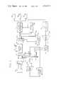
- FIG. 1is a schematic block diagram of a gas analyzer constructed in accordance with the invention
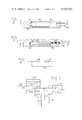
- FIG. 2is a full section view of an infrared source which may be employed in the analyzer of FIG. 1;
- FIG. 3is a cross-sectional view taken along the line 3--3 of FIG. 2;
- FIG. 4is a temperature stabilizing network which may be utilized in the gas analyzer of FIG. 1;
- FIG. 5is a circuit diagram of one form of synchronizing electronics which may be utilized in the analyzer of FIG. 1.
- the gas analyzer of the inventioncomprises a sample cell for containing a gas mixture to be analyzed, means for producing and directing infrared energy through the sample cell, and means for detecting the infrared energy passing through the sample cell.
- the electrical signal produced from the detected infrared energyis processed to produce an output indicating the concentration of the constituents of the gas of the sample cell.
- a rotary filter wheelwhich successively and repetitively positions at least one filter in the path of the infrared energy, is enclosed by a housing and is maintained at a substantially constant temperature.
- the infrared energy sourcehas an emissivity characteristic which varies in a way that at least partially compensates for wavelength dependence of the response of the detector.
- the detectoris temperature-stabilized by thermoelectric means which either heat the temperature up or cool the temperature down with respect to the ambient temperature. Temperature compensation means are also provided in the signal processor to compensate for variation in the absorption characteristics of gas with temperature.
- the motor which drives the rotary filter wheelis servo-controlled by synchronizing pulses derived directly from the detected infrared signal.
- a power source 11provides power to an infrared source 13.
- the source 13is located at one end of an infrared optical path which terminates at the other end at a detector 15.
- a rotating filter wheel 17rotating on an axle 19 parallel to and displaced from the optical path.
- the energy emitted by the source 13passes the filter wheel 17 and enters a sample cell 21 through which the gas mixture being analyzed is passed. Gas enters the sample cell through an inlet port 23 and exits the sample cell through an outlet port 25.
- Infrared transparent windows 27 and 29are provided at opposite ends of the sample cell in the optical path so that infrared energy may pass through the gas contained in the sample cell and be detected by the detector 15.
- the detector 15, which may be of the lead-selenide type,produces an electrical signal representative of the infrared energy which it detects.
- the filter wheel 17carries a plurality of filters, each of which corresponds to the characteristic absorption wavelength of a particular gas being analyzed for. For example, if carbon dioxide is to be detected, a filter having a wavelength region centered around 4.2 microns would be utilized in the filter wheel. In addition, a reference filter may be used having a wavelength centered close to but not overlapping with the wavelength of any of the gases present in the sample gas. As a result, the signal detected by the detector 15 will be a series of pulses, each pulse occurring when a particular filter is interposed in the path of the infrared energy. Between filters, the detected signal may drop to a background level and a sample of the background level may also be utilized in the processing electronics.
- the output of the detector 15is applied to the signal processing electronics 31.
- the signal processing electronicsmay be of any suitable design, analog or digital, which will produce an output indicating the concentration of the sought constituents of the gas mixture in the sample cell 21.
- As the reference filter is aligned in the optical patha measure of the basic sensitivity of the system to infrared radiation in general is obtained, including any attenuation of radiation by non-spectral contamination and the like on the infrared transparent windows of the sample cell.
- the sensitivity of the detector and the gain of the processing electronicsmay also be taken into account by this reference measurement.
- Each of the other filtersprovides radiation which ideally can only be absorbed if the specific gas to be detected through the use of that particular filter is present. Because these signals are affected by non-spectral contamination and the like identically with the reference signal, the reference signal can be used to minimize the effect of such phenomena. Because various signal processing techniques are well known in the prior art, further description of the signal processing electronics 31 will not be provided.
- the output of the signal processing electronicsis applied to the indicators 33, 35, and 37.
- the indicatorsmay be of any suitable design. Each of the indicators corresponds to a particular gas being analyzed for. Although three indicators are shown, it will be apparent that any number may be utilized.
- the synchronizing signal output of the synchronizing electronics 39is not only applied to the signal processing electronics 31, but is also applied to a servo-control loop for controlling the speed of the rotary filter wheel in accordance with the synchronizing pulses.
- the rotary filter wheel 17is driven on the axle 19 by a drum 41 and drive belt 43.
- the drive belt 43passes around the drum 41 and around a pulley 45 which is driven by a suitable motor 47.
- Power for the motor 47is provided by a motor drive circuit 49 which is voltage sensitive to regulate the speed of the motor 47.
- Such motor drive circuitsare well known in the art and will therefore not be described further herein.
- Voltageis applied to the motor drive circuit from an error amplifier 51.
- One input of the error amplifieris supplied by a frequency to voltage converter 53.
- the other input to the error amplifieris provided by a reference voltage source 55.
- Synchronizing pulses from the synchronizing electronics 39are applied to the frequency to voltage converter 53, which provides a voltage signal output representative of the frequency of the synchronizing pulses.
- This voltage outputis applied to the error amplifier, and the difference signal from the reference voltage is applied to the motor drive circuit to appropriately vary the speed of the motor 47. Accordingly, the detector optical pulse signal is utilized as the original source feedback information for control of the speed of the rotary filter wheel.
- a change in ambient temperature affecting the temperature of the various components of the systemmay significantly affect system stability.
- the location of the wavelength of the filtersnaturally affects the system stability.
- the resulting accuracy of the systemwill be affected, a phenomenon known as zero drift.
- an enclosure 57is provided surrounding the rotary filter wheel.
- the enclosure 57may include openings or transparent windows to allow passage of the infrared energy, and may also provide suitable openings for the belt 43.
- a heater 59is positioned inside the enclosure 57.
- a variable power source 61positioned outside the enclosure 57, is electrically connected to the heater 59 in order to provide power thereto.
- Connected to the variable power sourceis a comparator amplifier 63.
- One input of the comparator amplifieris connected to a temperature reference voltage 65, and the other is connected to a temperature sensor 67, for example a suitable thermistor.
- the temperature reference voltage at the terminal 65may be provided by a fixed resistor or the like, and the comparator amplifier servos the power delivered to the heater 59 to maintain the temperature sensor 67 at a constant temperature. In this manner, the temperature of the filter wheel 17 is maintained constant, minimizing the effects of zero drift.
- the temperature of the detectoris maintained constant.
- Prior art techniques for accomplishing thistypically have included means for cooling the detector to a level substantially below room temperature, or heating the detector substantially above room temperature. This unidirectional form of temperature regulation sometimes requires relatively large amounts of power, particularly where ambient temperature is high.
- the detector 15is maintained at a preselected temperature, for example room temperature, and is either cooled down or heated up from the ambient temperature as is necessary to maintain the preselected temperature.
- the detector 15is provided with a suitable housing 69 within which is mounted a thermistor or temperature transducer 71 and a thermoelectric heater-cooler 77.
- Thermistors and thermoelectric heater-coolersare well known in the art and will not be described further herein.
- the output of the thermistor or temperature transducer 71is applied to a comparator amplifier 79.
- the other input of the comparator amplifieris connected to a reference voltage 81.
- the comparator or error amplifieramplifies the difference between the two signals and applies it to the bidirectional power amplifier 83.
- the amplifier 83may be of any suitable type known in the art, and has one input connected to a positive voltage source 85 and another input connected to a negative voltage source 87.
- the amplifier 83causes the thermoelectric heater-cooler 77 to either increase or decrease the temperature of the detector 15 and the thermistor 71 within the housing 69 and therefore regulate the temperature of the detector 15. In this way, less power is required to maintain a constant temperature in the detector 15 than is typical of prior art devices. Because less cooling or heating effectiveness is required, the illustrated and described arrangement for maintaining constant detector temperature is also significantly lower in cost from typical prior art systems.
- the infrared source 13comprises an indirectly heated encapsulated tungsten metallized ceramic heater.
- the details of the sourceare shown in FIGS. 2 and 3.
- the tungsten heater 84is screen printed on alumina sheets and coated with a layer of insulating material. The assembly is then sintered at high temperature to produce a monolithic structure.
- the leads 86protrude from one end and the structure is mounted by a high temperature epoxy block 88 in a metal block 90.
- the metal blockhas a suitably shaped recess 92 to avoid contact with the heater 84, and is mounted to a heat sink 94 by means not shown.
- a window 96is provided communicating with the recess 92 and through which the infrared energy passes to the detector.
- One potential drawbackis maintaining the detector 15 at or near room temperature as above described is in the variation of detector response with wavelength.
- the typical lead-selenide detectorhas a response at carbon monoxide wavelengths which is much less than the response at hydrocarbon wavelengths.
- this differencemay be lessened by cooling the detector to 0° C. or lower, the cost saving advantages described above are no longer available.
- Differences in pulse amplitudesmay be accommodated by suitably constructing the signal processing electronics 31. However, this may significantly increase the costs of the electronics.
- the infrared source 13employs as the characteristic that its emissivity varies with the wavelengths in such a way as to at least partially compensate for the wavelength dependence of the response of the detector 15.
- a typical infrared sourcemay have a variation in emissivity with wavelength which is close to negligible.
- the variation of the response of a lead-selenide detector with wavelengthmay be as great as 60%, as is the case between HC and CO.
- the infrared source 13is selected to have an emissivity which varies substantially inversely in relation to the variation in response of the detector with wavelength.
- an infrared sourceis the ceramic heater available from Kyocera International Incorporated of Cupertino, Calif.
- This heaterfor example, has an emissivity of 0.5 for CO and an emissivity of 0.2 for HC at a temperature of 800° C.
- Another advantage of this particular heateris its relatively high temperature and large fraction of the emitter at the desired high temperature at wavelengths greater than 4.3 micrometers. In this range, the variation in emission with wavelength is minimized.
- the fraction of radiation at a given wavelength that is absorbed by a fixed concentration of gas in the sample cell 21will change if the temperature of the gas changes or if the interference filter in the filter wheel 17 does not completely cover the absorption band and either the filter or the gas temperature is allowed to change. Temperature stabilization of the filter wheel has been described above.
- the temperature dependence of the absorption of the gas in the sample cell 21 at any given wavelengthis compensated for by adding temperature sensitive resistor means, appropriately calibrated, in the signal processing means.
- Such temperature sensitive resistor meansmay be utilized to vary the gain of the signal processing means, such as by making the signal processing electronics temperature dependent and equal in magnitude, but opposite in sign, to that of the absorbed gaseous signal.
- provisionmay also be made to provide an electronic test signal for periodic calibration of the device whose value is temperature dependent in a way that is identical to that of the absorbed gaseous material.
- the span calibrationmay then be adjusted by the operator of the device to make the gain of the signal processing electronics agree with the test signal at each temperature.
- a networkmay be incorporated in either the signal processing electronics or the calibration electronics thereof as shown in FIG. 4.
- a resistor 89is series connected with a thermistor 92.
- a resistor 93is connected across the series combination of the resistor 89 and thermistor 91.
- the network shown in FIG. 4may be used to replace a suitable resistor in the processing electronics. For example, one of the gain determining resistors of the amplifiers may be replaced.
- a resistor in the electronic test signal networknot shown in detail but incorporated in the processing electronics, may be replaced by the thermistor network of FIG. 4.
- one networkmay be needed for each gas, or a single network may suffice.
- a resistor 95 and capacitor 97are series connected between the output of the detector and the negative input of an amplifier 99.
- a diode 101is connected across the negative input and the output of the amplifier 99 and the positive input of the amplifier 99 is grounded.
- a diode 103is connected in series with the output of the amplifier 99, and a resistor 105 and capacitor 107 are connected in parallel with each other across the series combination of the amplifier 99 and the diode 103.
- a diode 109is also series connected with the output of the amplifier 99.
- the diode 103is series connected through a resistor 111 to the positive input of a discriminator amplifier 113.
- a resistor 115is connected to the operational amplifier 113, and a load resistor 117 is connected from the junction between the diode 103 and the resistor 111 to ground.
- the resistor 117, resistor 111, resistor 115, and the operational amplifier 113together form a comparator.
- the function of a floating threshold networkis performed by resistors 119, 121, and 123, diodes 125 and 127, and capacitor 129.
- the resistor 119is series connected between the diode 109 and the negative input of the operational amplifier 113.
- the resistor 121is connected in series with the diodes 125 and 127 from the junction between the resistor 119 and the amplifier 113 to ground.
- the resistor 123is connected in parallel with the combination of the resistor 121 and diodes 125 and 127.
- the capacitor 129is connected in parallel with the resistor 123.
- the resistor 119attenuates the output of the amplifier 99, as does the resistor 123. On the rising edge of the output signal of the amplifier 99, the capacitor 129 follows the increasing signal or positive output.
- the capacitor 129together with the resistors 119 and 123 also serves as an R-C network which delays the decay time of the signal.
- the diode 109acts as a switch, in effect turning off the amplifier because of reverse bias. This makes the decay rate dependent on the amplitude of the derivative of the detector output.
- the threshold or switch pointfloats in accordance with the amplitude of the derivative signal, making it independent of the maximum amplitude of the pulses in the output of the detector.
- the inventionprovides an improved gas analyzer of the non-dispersive infrared type wherein temperature stability is provided, span stabilization is readily accomplished, and zero drift is minimized.
Landscapes
- Physics & Mathematics (AREA)
- Spectroscopy & Molecular Physics (AREA)
- Health & Medical Sciences (AREA)
- Life Sciences & Earth Sciences (AREA)
- Chemical & Material Sciences (AREA)
- Analytical Chemistry (AREA)
- Biochemistry (AREA)
- General Health & Medical Sciences (AREA)
- General Physics & Mathematics (AREA)
- Immunology (AREA)
- Pathology (AREA)
- Investigating Or Analysing Materials By Optical Means (AREA)
Abstract
Description
Claims (9)
Priority Applications (1)
| Application Number | Priority Date | Filing Date | Title |
|---|---|---|---|
| US05/948,674US4233513A (en) | 1978-10-05 | 1978-10-05 | Gas analyzer |
Applications Claiming Priority (1)
| Application Number | Priority Date | Filing Date | Title |
|---|---|---|---|
| US05/948,674US4233513A (en) | 1978-10-05 | 1978-10-05 | Gas analyzer |
Publications (1)
| Publication Number | Publication Date |
|---|---|
| US4233513Atrue US4233513A (en) | 1980-11-11 |
Family
ID=25488125
Family Applications (1)
| Application Number | Title | Priority Date | Filing Date |
|---|---|---|---|
| US05/948,674Expired - LifetimeUS4233513A (en) | 1978-10-05 | 1978-10-05 | Gas analyzer |
Country Status (1)
| Country | Link |
|---|---|
| US (1) | US4233513A (en) |
Cited By (27)
| Publication number | Priority date | Publication date | Assignee | Title |
|---|---|---|---|---|
| US4358679A (en)* | 1980-09-02 | 1982-11-09 | Astro Safety Products Inc. | Calibration of analyzers employing radiant energy |
| US4467435A (en)* | 1981-10-05 | 1984-08-21 | Beckman Instruments, Inc. | Infrared gas analyzer having detector elements of differing types |
| US4499378A (en)* | 1982-03-09 | 1985-02-12 | Horiba, Ltd. | Infrared radiation gas analyzer |
| US4499379A (en)* | 1982-03-09 | 1985-02-12 | Horiba, Ltd. | Infrared radiation gas analyzer |
| US4501968A (en)* | 1982-03-09 | 1985-02-26 | Horiba, Ltd. | Infrared radiation gas analyzer |
| US4549080A (en)* | 1983-06-17 | 1985-10-22 | Infrared Industries, Inc. | Double-pass flue gas analyzer |
| US4552164A (en)* | 1981-07-31 | 1985-11-12 | Tony Urella | Detection method and apparatus |
| US4569589A (en)* | 1983-05-25 | 1986-02-11 | University Of Pennsylvania | Lung water computer system |
| US4678914A (en)* | 1984-04-30 | 1987-07-07 | Environmental Tectonics Corporation | Digital IR gas analyzer |
| WO1987004240A1 (en)* | 1986-01-10 | 1987-07-16 | Andros Analyzers Incorporated | Infrared gas analyzer with automatic zero adjustment |
| US4687335A (en)* | 1985-12-09 | 1987-08-18 | Atlantic Richfield Company | Temperature compensation means for a radiometer |
| US4817013A (en)* | 1986-10-17 | 1989-03-28 | Nellcor, Inc. | Multichannel gas analyzer and method of use |
| WO1989009930A1 (en)* | 1988-04-15 | 1989-10-19 | Andros Analyzers Incorporated | An improved set point control circuit for an infrared gas analyzer |
| US5026992A (en)* | 1989-09-06 | 1991-06-25 | Gaztech Corporation | Spectral ratioing technique for NDIR gas analysis using a differential temperature source |
| US5127736A (en)* | 1982-02-22 | 1992-07-07 | Armco Inc. | Apparatus for measuring wear in the lining of refractory furnaces |
| US5433216A (en)* | 1993-06-14 | 1995-07-18 | Mountpelier Investments, S.A. | Intra-abdominal pressure measurement apparatus and method |
| US5479923A (en)* | 1992-10-16 | 1996-01-02 | Instrumentarium Corporation | Method and apparatus for analyzing a sample |
| US5570179A (en)* | 1993-12-16 | 1996-10-29 | Instrumentarium Oy | Measuring sensor and measuring arrangement for use in the analysis of gas mixtures |
| US5585635A (en)* | 1994-09-26 | 1996-12-17 | Marquette Electronics, Inc. | Infrared gas analyzer and method |
| US5870185A (en)* | 1996-10-21 | 1999-02-09 | C.F.C. Technology, Inc. | Apparatus and method for fluid analysis |
| US5908789A (en)* | 1996-03-14 | 1999-06-01 | Instrumentarium Oy | Analysis of gas mixtures with an infrared method |
| US5977546A (en)* | 1997-05-13 | 1999-11-02 | Carlson; Lee Richard | Self normalizing radiant energy monitor and apparatus for gain independent material quantity measurements |
| US6010453A (en)* | 1982-03-22 | 2000-01-04 | Instrumentarium Corporation | Tonometric catheter combination |
| US6238339B1 (en) | 1991-06-20 | 2001-05-29 | Instrumentarium Corp. | Remote sensing tonometric catheter apparatus and method |
| US6334064B1 (en) | 1988-08-26 | 2001-12-25 | Instrumentarium Corp. | Remote sensing tonometric catheter apparatus and method |
| US20040227928A1 (en)* | 2003-05-12 | 2004-11-18 | Honeywell International Inc. | High temperature pyrometer |
| CN103674883A (en)* | 2013-12-20 | 2014-03-26 | 中国科学技术大学 | Micro intermediate infrared gas concentration monitoring method and device |
Citations (4)
| Publication number | Priority date | Publication date | Assignee | Title |
|---|---|---|---|---|
| US3793525A (en)* | 1973-01-02 | 1974-02-19 | Philco Ford Corp | Dual cell non-dispersive gas analyzer |
| US3904880A (en)* | 1973-05-10 | 1975-09-09 | Honeywell Inc | Multi-component infrared analyzer |
| US3953734A (en)* | 1974-11-22 | 1976-04-27 | The United States Of America As Represented By The Administrator Of The National Aeronautics And Space Administration | Nulling device for detection of trace gases by NDIR absorption |
| US4013260A (en)* | 1974-09-27 | 1977-03-22 | Andros, Incorporated | Gas analyzer |
- 1978
- 1978-10-05USUS05/948,674patent/US4233513A/ennot_activeExpired - Lifetime
Patent Citations (4)
| Publication number | Priority date | Publication date | Assignee | Title |
|---|---|---|---|---|
| US3793525A (en)* | 1973-01-02 | 1974-02-19 | Philco Ford Corp | Dual cell non-dispersive gas analyzer |
| US3904880A (en)* | 1973-05-10 | 1975-09-09 | Honeywell Inc | Multi-component infrared analyzer |
| US4013260A (en)* | 1974-09-27 | 1977-03-22 | Andros, Incorporated | Gas analyzer |
| US3953734A (en)* | 1974-11-22 | 1976-04-27 | The United States Of America As Represented By The Administrator Of The National Aeronautics And Space Administration | Nulling device for detection of trace gases by NDIR absorption |
Cited By (34)
| Publication number | Priority date | Publication date | Assignee | Title |
|---|---|---|---|---|
| US4358679A (en)* | 1980-09-02 | 1982-11-09 | Astro Safety Products Inc. | Calibration of analyzers employing radiant energy |
| US4552164A (en)* | 1981-07-31 | 1985-11-12 | Tony Urella | Detection method and apparatus |
| US4467435A (en)* | 1981-10-05 | 1984-08-21 | Beckman Instruments, Inc. | Infrared gas analyzer having detector elements of differing types |
| US5127736A (en)* | 1982-02-22 | 1992-07-07 | Armco Inc. | Apparatus for measuring wear in the lining of refractory furnaces |
| US4499379A (en)* | 1982-03-09 | 1985-02-12 | Horiba, Ltd. | Infrared radiation gas analyzer |
| US4501968A (en)* | 1982-03-09 | 1985-02-26 | Horiba, Ltd. | Infrared radiation gas analyzer |
| US4499378A (en)* | 1982-03-09 | 1985-02-12 | Horiba, Ltd. | Infrared radiation gas analyzer |
| US6010453A (en)* | 1982-03-22 | 2000-01-04 | Instrumentarium Corporation | Tonometric catheter combination |
| US4569589A (en)* | 1983-05-25 | 1986-02-11 | University Of Pennsylvania | Lung water computer system |
| US4549080A (en)* | 1983-06-17 | 1985-10-22 | Infrared Industries, Inc. | Double-pass flue gas analyzer |
| US4678914A (en)* | 1984-04-30 | 1987-07-07 | Environmental Tectonics Corporation | Digital IR gas analyzer |
| US4687335A (en)* | 1985-12-09 | 1987-08-18 | Atlantic Richfield Company | Temperature compensation means for a radiometer |
| WO1987004240A1 (en)* | 1986-01-10 | 1987-07-16 | Andros Analyzers Incorporated | Infrared gas analyzer with automatic zero adjustment |
| US4687934A (en)* | 1986-01-10 | 1987-08-18 | Andros Analyzers Incorporated | Infrared gas analyzer with automatic zero adjustment |
| US4817013A (en)* | 1986-10-17 | 1989-03-28 | Nellcor, Inc. | Multichannel gas analyzer and method of use |
| AU617178B2 (en)* | 1988-04-15 | 1991-11-21 | Andros Analyzers Incorporated | An improved set point control circuit for an infrared gas analyzer |
| WO1989009930A1 (en)* | 1988-04-15 | 1989-10-19 | Andros Analyzers Incorporated | An improved set point control circuit for an infrared gas analyzer |
| EP0420858A4 (en)* | 1988-04-15 | 1991-12-04 | Andros Analyzers Incorporated | An improved set point control circuit for an infrared gas analyzer |
| US4918311A (en)* | 1988-04-15 | 1990-04-17 | Andros Analyzers Incorporated | Set point control circuit for an infrared gas analyzer |
| US6334064B1 (en) | 1988-08-26 | 2001-12-25 | Instrumentarium Corp. | Remote sensing tonometric catheter apparatus and method |
| US5026992A (en)* | 1989-09-06 | 1991-06-25 | Gaztech Corporation | Spectral ratioing technique for NDIR gas analysis using a differential temperature source |
| US6238339B1 (en) | 1991-06-20 | 2001-05-29 | Instrumentarium Corp. | Remote sensing tonometric catheter apparatus and method |
| US5479923A (en)* | 1992-10-16 | 1996-01-02 | Instrumentarium Corporation | Method and apparatus for analyzing a sample |
| US6134462A (en)* | 1992-10-16 | 2000-10-17 | Instrumentarium Corp. | Method and apparatus for analyzing a sample |
| US5433216A (en)* | 1993-06-14 | 1995-07-18 | Mountpelier Investments, S.A. | Intra-abdominal pressure measurement apparatus and method |
| US5570179A (en)* | 1993-12-16 | 1996-10-29 | Instrumentarium Oy | Measuring sensor and measuring arrangement for use in the analysis of gas mixtures |
| US5585635A (en)* | 1994-09-26 | 1996-12-17 | Marquette Electronics, Inc. | Infrared gas analyzer and method |
| US5908789A (en)* | 1996-03-14 | 1999-06-01 | Instrumentarium Oy | Analysis of gas mixtures with an infrared method |
| US5870185A (en)* | 1996-10-21 | 1999-02-09 | C.F.C. Technology, Inc. | Apparatus and method for fluid analysis |
| US5977546A (en)* | 1997-05-13 | 1999-11-02 | Carlson; Lee Richard | Self normalizing radiant energy monitor and apparatus for gain independent material quantity measurements |
| US20040227928A1 (en)* | 2003-05-12 | 2004-11-18 | Honeywell International Inc. | High temperature pyrometer |
| US7075629B2 (en)* | 2003-05-12 | 2006-07-11 | Honeywell International Inc. | High temperature pyrometer |
| CN103674883A (en)* | 2013-12-20 | 2014-03-26 | 中国科学技术大学 | Micro intermediate infrared gas concentration monitoring method and device |
| CN103674883B (en)* | 2013-12-20 | 2016-05-25 | 中国科学技术大学 | A kind of miniature middle infrared-gas concentration monitoring method and device |
Similar Documents
| Publication | Publication Date | Title |
|---|---|---|
| US4233513A (en) | Gas analyzer | |
| US4013260A (en) | Gas analyzer | |
| US5886348A (en) | Non-dispersive infrared gas analyzer with interfering gas correction | |
| US5464983A (en) | Method and apparatus for determining the concentration of a gas | |
| US5261415A (en) | CO2 mainstream capnography sensor | |
| US4346296A (en) | Non-dispersive infrared gas analyzer | |
| US4730112A (en) | Oxygen measurement using visible radiation | |
| US5542285A (en) | Method and apparatus for transient temperature compensation in gas analyzer equipment | |
| US3860818A (en) | Atmospheric pollution monitor | |
| US4177381A (en) | Gas analyzer sample cell | |
| EP1036311B1 (en) | Gas detection apparatus using a combined infrared source and high temperature bolometer | |
| US4596931A (en) | Method of eliminating measuring errors in photometric analysis | |
| CA1224944A (en) | Infrared fluid analyzer | |
| US4480191A (en) | Automatic gain control for an infrared source of an automotive emissions analyzer | |
| US3837744A (en) | Spectrometers | |
| EP0022789B1 (en) | Gas analyzer and gaz analyzing method | |
| US4398091A (en) | Temperature compensated gas analyzer | |
| US5905270A (en) | Apparatus for detecting the presence of a light absorbing gas within an atmosphere containing the gas | |
| US4035644A (en) | Atmospheric condition detecting and indicating apparatus and method | |
| US3039006A (en) | Radiometers with linearized final output | |
| US2758215A (en) | Pulsed stabilized infra-red detection system | |
| US4016423A (en) | Infrared analyzer of constant radiant energy | |
| US4283934A (en) | Pyrometric temperature measurements in flameless atomic absorption spectroscopy | |
| US3787694A (en) | Fluidic detector for the detection of radiant energy and for the analysis of gas mixtures | |
| SU1286985A1 (en) | Method of determining concentration of combustible gases |
Legal Events
| Date | Code | Title | Description |
|---|---|---|---|
| AS | Assignment | Owner name:BANQUE PARIBAS, AS ADMINISTRATIVE AGENT, CALIFORNI Free format text:SECURITY INTEREST;ASSIGNOR:ANDROS INCORPORATED;REEL/FRAME:007945/0517 Effective date:19960514 | |
| AS | Assignment | Owner name:ANDROS, INC., CALIFORNIA Free format text:RELEASE OF LIENS;ASSIGNOR:BNP PARIBAS, FKA BANQUE PARIBAS;REEL/FRAME:011084/0596 Effective date:20000728 | |
| AS | Assignment | Owner name:A.C., INC., CALIFORNIA Free format text:ASSIGNMENT OF ASSIGNORS INTEREST;ASSIGNOR:ANDROS, INC.;REEL/FRAME:011356/0625 Effective date:20000726 | |
| AS | Assignment | Owner name:NEW A.C., INC., CALIFORNIA Free format text:CORRECTIVE ASSIGNMENT TO CORRECT THE ASSIGNEE NAME PREVIOUSLY RECORDED ON REEL 011336, FRAME 0625;ASSIGNOR:ANDROS, INC.;REEL/FRAME:011751/0170 Effective date:20000726 | |
| AS | Assignment | Owner name:COMERICA BANK, MICHIGAN Free format text:SECURITY AGREEMENT;ASSIGNOR:NEW A.C., INC.;REEL/FRAME:023032/0755 Effective date:20070412 |