US4233029A - Liquid transport device and method - Google Patents
Liquid transport device and methodDownload PDFInfo
- Publication number
- US4233029A US4233029AUS05/954,689US95468978AUS4233029AUS 4233029 AUS4233029 AUS 4233029AUS 95468978 AUS95468978 AUS 95468978AUS 4233029 AUS4233029 AUS 4233029A
- Authority
- US
- United States
- Prior art keywords
- liquid
- grooves
- zone
- flow
- paths
- Prior art date
- Legal status (The legal status is an assumption and is not a legal conclusion. Google has not performed a legal analysis and makes no representation as to the accuracy of the status listed.)
- Expired - Lifetime
Links
- 239000007788liquidSubstances0.000titleclaimsabstractdescription192
- 238000000034methodMethods0.000titleclaimsabstractdescription25
- 230000002093peripheral effectEffects0.000claimsabstractdescription18
- 230000004888barrier functionEffects0.000claimsdescription16
- 239000000463materialSubstances0.000claimsdescription15
- 238000012360testing methodMethods0.000claimsdescription12
- 230000007480spreadingEffects0.000claimsdescription7
- 238000003892spreadingMethods0.000claimsdescription7
- 238000004458analytical methodMethods0.000claimsdescription6
- 230000008569processEffects0.000claimsdescription4
- 239000003153chemical reaction reagentSubstances0.000claimsdescription3
- 238000006243chemical reactionMethods0.000claimsdescription2
- 238000009826distributionMethods0.000claimsdescription2
- 239000012530fluidSubstances0.000claims3
- 210000002966serumAnatomy0.000description11
- 230000000694effectsEffects0.000description6
- 230000005499meniscusEffects0.000description6
- 238000009736wettingMethods0.000description4
- 230000009471actionEffects0.000description3
- 238000013461designMethods0.000description3
- 229920002284Cellulose triacetatePolymers0.000description2
- NNLVGZFZQQXQNW-ADJNRHBOSA-N[(2r,3r,4s,5r,6s)-4,5-diacetyloxy-3-[(2s,3r,4s,5r,6r)-3,4,5-triacetyloxy-6-(acetyloxymethyl)oxan-2-yl]oxy-6-[(2r,3r,4s,5r,6s)-4,5,6-triacetyloxy-2-(acetyloxymethyl)oxan-3-yl]oxyoxan-2-yl]methyl acetateChemical compoundO([C@@H]1O[C@@H]([C@H]([C@H](OC(C)=O)[C@H]1OC(C)=O)O[C@H]1[C@@H]([C@@H](OC(C)=O)[C@H](OC(C)=O)[C@@H](COC(C)=O)O1)OC(C)=O)COC(=O)C)[C@@H]1[C@@H](COC(C)=O)O[C@@H](OC(C)=O)[C@H](OC(C)=O)[C@H]1OC(C)=ONNLVGZFZQQXQNW-ADJNRHBOSA-N0.000description2
- 239000012491analyteSubstances0.000description2
- 238000013459approachMethods0.000description2
- 230000015572biosynthetic processEffects0.000description2
- 238000010276constructionMethods0.000description2
- 239000003792electrolyteSubstances0.000description2
- 238000005259measurementMethods0.000description2
- 229910052751metalInorganic materials0.000description2
- 239000002184metalSubstances0.000description2
- -1polyethylenePolymers0.000description2
- 238000012545processingMethods0.000description2
- 150000003839saltsChemical class0.000description2
- 239000000523sampleSubstances0.000description2
- 238000003466weldingMethods0.000description2
- 229920008347Cellulose acetate propionatePolymers0.000description1
- 239000004698PolyethyleneSubstances0.000description1
- 239000004743PolypropyleneSubstances0.000description1
- 239000004793PolystyreneSubstances0.000description1
- 150000001242acetic acid derivativesChemical class0.000description1
- 239000002253acidSubstances0.000description1
- 229920000122acrylonitrile butadiene styrenePolymers0.000description1
- 239000000853adhesiveSubstances0.000description1
- 230000001070adhesive effectEffects0.000description1
- 239000011230binding agentSubstances0.000description1
- 210000004369bloodAnatomy0.000description1
- 239000008280bloodSubstances0.000description1
- 238000004159blood analysisMethods0.000description1
- 230000015556catabolic processEffects0.000description1
- 229920006217cellulose acetate butyratePolymers0.000description1
- 230000008859changeEffects0.000description1
- 239000003795chemical substances by applicationSubstances0.000description1
- 150000001875compoundsChemical class0.000description1
- 238000007796conventional methodMethods0.000description1
- 230000007812deficiencyEffects0.000description1
- 230000003111delayed effectEffects0.000description1
- 238000004090dissolutionMethods0.000description1
- 230000008030eliminationEffects0.000description1
- 238000003379elimination reactionMethods0.000description1
- 238000004049embossingMethods0.000description1
- 239000011521glassSubstances0.000description1
- 230000002209hydrophobic effectEffects0.000description1
- 230000005661hydrophobic surfaceEffects0.000description1
- 230000001788irregularEffects0.000description1
- 230000002934lysing effectEffects0.000description1
- 238000004519manufacturing processMethods0.000description1
- 239000012528membraneSubstances0.000description1
- QSHDDOUJBYECFT-UHFFFAOYSA-NmercuryChemical compound[Hg]QSHDDOUJBYECFT-UHFFFAOYSA-N0.000description1
- 229910052753mercuryInorganic materials0.000description1
- 239000003595mistSubstances0.000description1
- 238000012986modificationMethods0.000description1
- 230000004048modificationEffects0.000description1
- 239000004033plasticSubstances0.000description1
- 229920003023plasticPolymers0.000description1
- 239000004417polycarbonateSubstances0.000description1
- 229920000515polycarbonatePolymers0.000description1
- 229920000573polyethylenePolymers0.000description1
- 229920001155polypropylenePolymers0.000description1
- 229920002223polystyrenePolymers0.000description1
- 230000002035prolonged effectEffects0.000description1
- 230000005855radiationEffects0.000description1
- 238000000926separation methodMethods0.000description1
- 239000002904solventSubstances0.000description1
- 125000006850spacer groupChemical group0.000description1
- 238000004381surface treatmentMethods0.000description1
- 239000012780transparent materialSubstances0.000description1
Images


Classifications
- B—PERFORMING OPERATIONS; TRANSPORTING
- B01—PHYSICAL OR CHEMICAL PROCESSES OR APPARATUS IN GENERAL
- B01L—CHEMICAL OR PHYSICAL LABORATORY APPARATUS FOR GENERAL USE
- B01L3/00—Containers or dishes for laboratory use, e.g. laboratory glassware; Droppers
- B01L3/50—Containers for the purpose of retaining a material to be analysed, e.g. test tubes
- B01L3/502—Containers for the purpose of retaining a material to be analysed, e.g. test tubes with fluid transport, e.g. in multi-compartment structures
- B01L3/5027—Containers for the purpose of retaining a material to be analysed, e.g. test tubes with fluid transport, e.g. in multi-compartment structures by integrated microfluidic structures, i.e. dimensions of channels and chambers are such that surface tension forces are important, e.g. lab-on-a-chip
- B01L3/50273—Containers for the purpose of retaining a material to be analysed, e.g. test tubes with fluid transport, e.g. in multi-compartment structures by integrated microfluidic structures, i.e. dimensions of channels and chambers are such that surface tension forces are important, e.g. lab-on-a-chip characterised by the means or forces applied to move the fluids
- B—PERFORMING OPERATIONS; TRANSPORTING
- B01—PHYSICAL OR CHEMICAL PROCESSES OR APPARATUS IN GENERAL
- B01L—CHEMICAL OR PHYSICAL LABORATORY APPARATUS FOR GENERAL USE
- B01L3/00—Containers or dishes for laboratory use, e.g. laboratory glassware; Droppers
- B01L3/50—Containers for the purpose of retaining a material to be analysed, e.g. test tubes
- B01L3/502—Containers for the purpose of retaining a material to be analysed, e.g. test tubes with fluid transport, e.g. in multi-compartment structures
- B01L3/5027—Containers for the purpose of retaining a material to be analysed, e.g. test tubes with fluid transport, e.g. in multi-compartment structures by integrated microfluidic structures, i.e. dimensions of channels and chambers are such that surface tension forces are important, e.g. lab-on-a-chip
- B01L3/502746—Containers for the purpose of retaining a material to be analysed, e.g. test tubes with fluid transport, e.g. in multi-compartment structures by integrated microfluidic structures, i.e. dimensions of channels and chambers are such that surface tension forces are important, e.g. lab-on-a-chip characterised by the means for controlling flow resistance, e.g. flow controllers, baffles
- G—PHYSICS
- G01—MEASURING; TESTING
- G01N—INVESTIGATING OR ANALYSING MATERIALS BY DETERMINING THEIR CHEMICAL OR PHYSICAL PROPERTIES
- G01N1/00—Sampling; Preparing specimens for investigation
- G01N1/28—Preparing specimens for investigation including physical details of (bio-)chemical methods covered elsewhere, e.g. G01N33/50, C12Q
- B—PERFORMING OPERATIONS; TRANSPORTING
- B01—PHYSICAL OR CHEMICAL PROCESSES OR APPARATUS IN GENERAL
- B01L—CHEMICAL OR PHYSICAL LABORATORY APPARATUS FOR GENERAL USE
- B01L2300/00—Additional constructional details
- B01L2300/06—Auxiliary integrated devices, integrated components
- B01L2300/0627—Sensor or part of a sensor is integrated
- B01L2300/0645—Electrodes
- B—PERFORMING OPERATIONS; TRANSPORTING
- B01—PHYSICAL OR CHEMICAL PROCESSES OR APPARATUS IN GENERAL
- B01L—CHEMICAL OR PHYSICAL LABORATORY APPARATUS FOR GENERAL USE
- B01L2300/00—Additional constructional details
- B01L2300/08—Geometry, shape and general structure
- B01L2300/0809—Geometry, shape and general structure rectangular shaped
- B01L2300/0816—Cards, e.g. flat sample carriers usually with flow in two horizontal directions
- B—PERFORMING OPERATIONS; TRANSPORTING
- B01—PHYSICAL OR CHEMICAL PROCESSES OR APPARATUS IN GENERAL
- B01L—CHEMICAL OR PHYSICAL LABORATORY APPARATUS FOR GENERAL USE
- B01L2300/00—Additional constructional details
- B01L2300/08—Geometry, shape and general structure
- B01L2300/089—Virtual walls for guiding liquids
- B—PERFORMING OPERATIONS; TRANSPORTING
- B01—PHYSICAL OR CHEMICAL PROCESSES OR APPARATUS IN GENERAL
- B01L—CHEMICAL OR PHYSICAL LABORATORY APPARATUS FOR GENERAL USE
- B01L2300/00—Additional constructional details
- B01L2300/16—Surface properties and coatings
- B01L2300/161—Control and use of surface tension forces, e.g. hydrophobic, hydrophilic
- B01L2300/165—Specific details about hydrophobic, oleophobic surfaces
- B01L2300/166—Suprahydrophobic; Ultraphobic; Lotus-effect
- B—PERFORMING OPERATIONS; TRANSPORTING
- B01—PHYSICAL OR CHEMICAL PROCESSES OR APPARATUS IN GENERAL
- B01L—CHEMICAL OR PHYSICAL LABORATORY APPARATUS FOR GENERAL USE
- B01L2400/00—Moving or stopping fluids
- B01L2400/04—Moving fluids with specific forces or mechanical means
- B01L2400/0403—Moving fluids with specific forces or mechanical means specific forces
- B01L2400/0406—Moving fluids with specific forces or mechanical means specific forces capillary forces
- B—PERFORMING OPERATIONS; TRANSPORTING
- B01—PHYSICAL OR CHEMICAL PROCESSES OR APPARATUS IN GENERAL
- B01L—CHEMICAL OR PHYSICAL LABORATORY APPARATUS FOR GENERAL USE
- B01L2400/00—Moving or stopping fluids
- B01L2400/08—Regulating or influencing the flow resistance
- B01L2400/084—Passive control of flow resistance
- B01L2400/086—Passive control of flow resistance using baffles or other fixed flow obstructions
- Y—GENERAL TAGGING OF NEW TECHNOLOGICAL DEVELOPMENTS; GENERAL TAGGING OF CROSS-SECTIONAL TECHNOLOGIES SPANNING OVER SEVERAL SECTIONS OF THE IPC; TECHNICAL SUBJECTS COVERED BY FORMER USPC CROSS-REFERENCE ART COLLECTIONS [XRACs] AND DIGESTS
- Y10—TECHNICAL SUBJECTS COVERED BY FORMER USPC
- Y10T—TECHNICAL SUBJECTS COVERED BY FORMER US CLASSIFICATION
- Y10T436/00—Chemistry: analytical and immunological testing
- Y10T436/25—Chemistry: analytical and immunological testing including sample preparation
Definitions
- This inventionis directed to a device and method for transporting liquid in controlled, predetermined flow patterns, and, more specifically, to such a device and method that transport liquid across a surface with the menisci of the liquid advancing as wave fronts having a controlled peripheral configuration.
- the non-uniform smoothness of the exposed surfaces in such devicescharacteristically results in uncontrolled and undirected capillary flow of the liquid across those surfaces.
- the consequences of such uncontrolled flowinclude the possibility of forming trapped air pockets and thus the incomplete wetting of certain portions of the surface. Air pockets are particularly undesirable when undertaking automatic, possibly microscopic, examination of the liquid and/or the wetted surfaces. Such examination cannot tolerate the absence of the liquid in the relevant scanning area, as automated equipment is not capable of ignoring such unwetted areas. Air pockets are a common occurrence when wetting or filling zones of tortuous configuration, e.g., those containing corners around which the liquid must flow.
- This inventionconcerns the discovery of a liquid transport device and method of transport that solves the aforementioned problems by providing a predetermined liquid flow pattern at a controlled rate across a desired surface area.
- a liquid transport devicecomprising two opposing surfaces, spaced apart a distance effective to induce capillary flow of such liquid, and means to permit the introduction of the liquid between the surfaces.
- Each of the surfacesincludes, across at least a portion thereof, means for directing the capillary flow of introduced liquid along predetermined paths.
- the directing means on each surfaceare relatively oriented so that at least a portion of the paths dictated by one of the surfaces forms a positive angle with respect to the paths dictated by the directly opposing portion of the other surface.
- capillary flow of liquid introduced between the surfacesoccurs multidirectionally across the surfaces with a predetermined peripheral configuration.
- the inventionprovides a method of transporting a liquid with a predetermined peripheral configuration while maintaining capillary action.
- the methodcomprises the steps of introducing liquid between two opposing surfaces that are spaced apart a distance effective to induce capillary flow in the liquid and provide therebetween a transport zone, directing a portion of the introduced liquid to flow across one of the surfaces along a predetermined first series of paths, and simultaneously directing another portion of the introduced liquid to flow across the other surface along a predetermined second series of paths at least a portion of which forms a positive angle with respect to the directly opposing portion of the first path series, whereby the liquid flows multidirectionally between the surfaces.
- a liquid transport device and methodwhich insure that liquid flows throughout a defined zone in accordance with a predetermined pattern and in a controlled manner.
- Yet another aspect of the inventionis to provide a device and method of liquid transport that insure predictable and controlled flow rates in defined areas.
- Still another aspect of the inventionis that liquid is transported in the manner described by a device that is entirely passive.
- passive devicesare desirable because they do not require the use of moving parts such as are found in pumps and the like. Passiveness drastically reduces costs, eliminates a primary source of breakdowns, and enhances miniaturization.
- FIG. 1is an isometric view of a transport device prepared in accordance with the invention, the spacing between parts being exaggerated for clarity;
- FIG. 2is an enlarged, fragmentary sectional view of the device of FIG. 1, the width of the grooves and the spacing between surfaces being exaggerated for clarity;
- FIG. 3is a fragmentary perspective view taken generally along the line III--III of FIG. 2, portions of the liquid in contact with the upper member having been deleted for clarity;
- FIGS. 4-6are plan views of devices like that shown in FIG. 1, illustrating several alternate embodiments thereof and particularly alternate liquid transport patterns;
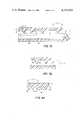
- FIGS. 7a and 7bare fragmentary sectional views similar to FIG. 2, illustrating dimensional variables and alternate configurations of the device;
- FIGS. 8a and 8bare fragmentary sectional views illustrating the effect of varying angle beta
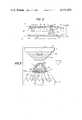
- FIG. 9is an isometric view of an embodiment of the invention, in a device for analyzing ionic activity of electrolytes of a liquid;
- FIG. 10is a fragmentary sectional view taken generally along the line X--X of FIG. 9;
- FIG. 11is a plan view of the ion bridge or FIG. 9, illustrating the advancing liquid wave fronts during use.
- FIG. 12is a fragmentary plan view of yet another embodiment of the invention.
- the liquid transport device of this inventionis applicable to the transport, also described as “spreading", of any liquid over a surface area or through transport zones of many sizes and shapes, flat or curved, regardless of end uses, provided that the surfaces and liquid involved are capable of providing capillary transport.
- the inventionprovides such liquid transport in a controlled, multidirectional manner, to produce a predetermined peripheral configuration.
- any two generally parallel surfaces with appropriate directing meanscan be used, provided the opposed surfaces are spaced apart a distance that will permit capillary flow of liquid introduced between the members. This distance need not be uniform throughout the device, that is, exact parallism need not be maintained, as long as capillary flow is maintained as further described hereafter.
- Useful parallel surfacesinclude curved parallel surfaces, e.g., cylindrical or spherical members one of which has a concave surface that is generally concentric with an opposing convex surface of the other member.
- liquids advantageously transported by this deviceinclude both aqueous and non-aqueous liquids with or without dissolved, dispersed, or emulsified addenda.
- the device and methodhave been found particularly useful for transport of blood and blood serum.
- a liquid transport or spreading device 10 constructed in accordance with the invention to have superior transport propertiescomprises, FIGS. 1-3, two members 12 and 14 having opposing surfaces 16 and 18, respectively, and additional edge surfaces 20, 22 and back surfaces 24 on the sides of the members opposite to surfaces 16 and 18.
- Meansare provided on surfaces 16 and 18 to control and direct flow of liquid across at least a portion of, and preferably the entire area of, those surfaces.
- a space of thickness "s"is provided between members 12 and 14. (See FIG. 2). Dimension s is selected to insure that capillary flow of liquid will occur between surfaces 16 and 18, under the influence of directing means 42 and 44.
- capillary flowor “capillary transport” is that flow or transport of liquid that occurs between confining surfaces, wettable by that liquid, due to surface tension in the meniscus of the liquid between the surfaces.
- capillary flowis a function of the space "s" between the confining surfaces, and the limit to which such space can be extended depends upon the properties of a given liquid.
- the space s between the members and the area of surfaces 16 and 18define the volume of the transport zone.
- the two members 12 and 14can be held apart distance s by a number of constructions, such as a spacer member, not shown, interposed at appropriate intervals through portions of the transport zone.
- surface 16can be supported spaced away from surface 18 along or adjacent to edges 20 and 22.
- At least one of surfaces 16 and 18is selected from a wettable material that is substantially impervious to the liquid to be transported.
- a "wettable surface”is one which, for the liquid to be transported, provides a liquid-vapor contact angle which is less than 90°. Such a contact angle insures the liquid will wet the surfaces to some extent, and is in contrast to the angle that exists when using the same surface material with a liquid such as mercury.
- a "substantially impervious" surface or materialis one with respect to which substantially all of the liquid to be transported will move across, rather than penetrate through or into to any appreciable extent.
- a highly useful embodimentis one wherein both surfaces 16 and 18 comprise a material that is substantially impervious to the transported liquid. As will also be apparent, any listing of such materials depends upon the nature of the particular liquid to be transported, and selection of the appropriate material will be readily evident in light of such liquid.
- a liquid access aperture 26is provided in member 12, extending from surface 24 to surface 16 and disposed above surface 18.
- the size and shape of the aperturepreferably are such as will direct liquid into contact with the surfaces bounding the transport zone. This is, both the surfaces 16 and 18 must be wetted by the continuous volume of the drop, and aperture 26 has a configuration that is not too small to permit this.
- the transverse dimension of the aperturecan also be so large as to prevent contact between the upper surface and a centered drop, but if the drop volume is increased, this deficiency can be overcome.
- a suitably sized droptherefore should have a volume which at least equals the sum of the volume of aperture 26 and the volume of the transport zone that is to be filled by the liquid.
- Convenient drop volumesare those between about 5 and about 1000 ⁇ l. The choice of course depends upon the end use of the device. For best results in driving the drop of liquid into the center of the aperture 26, and thus into the transport zone, it is preferred that the shape of the aperture be a regular hexagon, not shown, rather than a circle.
- the space between members 12 and 14 left exposed at either edge 20 or 22can serve as the means to permit the liquid to be introduced.
- the spacing between surfaces 16 and 18preferably causes the liquid to wet both surfaces.
- a highly preferred form of the directing means in surfaces 16 and 18comprises a pattern of exposed grooves 42 and 44, respectively, in each of such surfaces.
- grooverefers to a channel, depression or the like and thus each of grooves 42 and 44 is, FIG. 2, the space between two adjacent ridges 46 and 48, respectively.
- the grooves and ridges of one surfaceare disposed at an angle alpha ( ⁇ ) with respect to the grooves and ridges of the other surface, as is described in detail hereinafter.
- Each ridgehas a top portion or edge 50.
- FIGS. 2 and 3illustrate the manner in which device 10 is effective to provide controlled multidirectional flow.
- a quantity of liquid "L" of a volume sufficient to wet both surfaces 16 and 18is placed in aperture 26.
- the condition shown in FIG. 2is unstable and immediately the menisci m 1 and m 2 of the liquid move to the positions shown in phantom, filling the width of one groove 42. Meanwhile flow also advances along the length of groove 42. It is observed that a multidirectional flow soon develops, providing a peripheral configuration comprising wave fronts that conform to the linearity, or curvilinearity of the grooves or ridges.
- the groove 42' beyond that ridgeis a barrier to further flow until the rest of the liquid flowing across groove 42 reaches that ridge. More precisely, although the energy levels favor movement of the liquid to the top portion 50 of ridge 46', the edge at 50 created by the adjacent groove 42' is a temporary energy barrier to further flow by the meniscus into groove 42'. Therefore, less energy represents an increased spacing between the opposed surfaces and is thus required to pull any remaining, lagging portion of m 2 up to the top of ridge 46' than is required to move the leading portion of the meniscus shown in phantom at ridge 46', beyond that ridge.
- a portion of meniscus m 2moves or "jumps" to the next left-hand ridge (not shown).
- the energy levelsfavor the movement of all of meniscus m 2 to that next ridge before movement continues beyond.
- liquid flow within groove 44appears to be directed by the energy barriers or levels represented by the grooves or ridges, respectively, to jump repeatedly from ridge 46 to ridge 46 one ridge at a time.
- a wave front 60is formed, FIG. 3, having the linearity or curvilinearity of ridges 46. This wave front advances in the direction of arrows 62.
- wave fronts 64are formed such that, when a portion of the front moves to the next adjacent ridge 48, the energy levels favor the movement of the trailing or remaining portion of the wave front to that same adjacent ridge before the advance portion of the front 64 can move on. As a result, wave fronts 64 take on the linearity or curvilinearity of ridges 48.
- the ridge-jumping processcontinues until the source of liquid L in aperture 26 ceases to have sufficient volume to continue feeding the advancing wave fronts, or the capillary spacing between surfaces 16 and 18 terminates at a boundary of the transport zone such as at edge surfaces 20 or 22, whereby further capillary flow is prevented. If capillary flow ceases because of an open boundary such as at edges 20 or 22, such a boundary can be described as a flow-terminating energy barrier.
- the wave frontsdo not accidentally meet each other as in conventional designs so as to confine and trap an air pocket in the transport zone. Instead, the entire area of surfaces 16 and 18 is wetted, and the entire transport zone, defined by such surface areas and the space between them, is filled. Of course, should it be desired, controlled flow to form an air pocket could be achieved.
- the multidirectional flow achieved by the device as describedis the overall flow occurring in two or more non-aligned directions as primarily distinguished from unidirectional flow.
- the multidirectional flowcan occur generally in a planar manner, if the opposed surfaces are generally flat, or it can occur three dimensionally if the surfaces are curved.
- FIG. 3is only an estimate of the microscopic shape of such wave fronts, especially as seen elevationally. It is believed the wave fronts actually have a curvature about an axis, and specifically that wave front 60 has an axis of curvature 68 and wave fronts 64 an axis of curvature 70. However, whatever the actual microscopic curvature of the wave fronts, e.g., as might appear in a perspective view such as FIG. 3, such is not critical and does not affect the observed overall linearity or curvilinearity of the wave fronts when viewed in plan. In any case, the overall flow of the wave fronts is multidirectionally controlled with a predetermined peripheral configuration.
- each surfaceis preferably continuous; that is, each groove extends either all the way across surface 16 or 18, from an edge 20 or 22 to the opposite edge, or the groove closes upon itself, as in a closed curve, without a break.
- small breaks in the ridges forming the groovescan be tolerated as they will affect the control of the wave fronts to only a negligible extent.
- each of the grooveshas a substantially greater length than width, as determined by the adjacent ridges.
- Each pattern of groovese.g., grooves 42, provides at least a first predetermined series of flow paths, that is, in the directions of the grooves' lengths. Such directions are the primary flow directions of the grooves.
- grooves 42are illustrated as having a length extending in substantially parallel straight lines, providing essentially straight flow paths.
- the pattern of grooves 44provides at least a second predetermined series of flow paths, extending in the directions along the lengths of grooves 44.
- Grooves 44, FIGS. 1 and 2are also illustrated as having a length extending in substantially parallel straight lines.
- the grooves of the respective surfacesare disposed so that the grooves, and therefore the paths of flow of one surface, form an angle alpha ( ⁇ ) with respect to the directly opposed portions of the grooves and therefore the paths of flow, of the other surface, FIGS. 1 and 3.
- the term "directly opposed” as used in reference to a portion of a path or groove of a surface,means a portion that is disposed directly above or below a point, hereinafter "superposition point", on a respective path or groove of the other surface.
- the angle existing between the two paths or the two grooves of the two surfaces, at the superposition pointis angle alpha.
- angle alphais measured in a plane parallel to one of the surfaces at the superposition point.
- angle alphais positive, that is, non-zero, for at least a portion of the transport zone, and in the case of the patterns of FIG. 1, for the entire transport zone. It is the presence of this positive angle that insures that liquid introduced at aperture 26 will flow through the transport zone in the controlled, multidirectional manner described above.
- the actual shape or pattern of such overall flowdepends upon the value of alpha, the flow rate within the grooves, as described hereinafter, and the curvilinearity, if any, of the lengthwise extension of the ridges (or grooves).
- alphacan be 90°, and in these instances, with substantially parallel, straight grooves 42 and 44, a substantially rectilinear flow pattern proceeds, FIG. 4. That is, wave fronts 60 and 64 are generally perpendicular to each other to provide a predetermined peripheral configuration controlled to the shape of a rectangle. After a passage of time, the wave fronts 60' and 64' are still generally perpendicular.
- angle alphahas a value of 45°.
- the flow patternbecomes rhomboidal, as delineated by wave fronts 74 and 76.
- FIG. 6in device 10a grooves 42a, visible through transparent member 12a, are concentric circles centered upon aperture 26a. Grooves 44a are substantially straight and parallel as before. A flow pattern having an approximately hour-glass shape forms as wave front 80 advances, with the long axis extending in the direction of straight grooves 44a. In such a case, angle alpha varies within the pattern from 0° to 90°.
- Flow of wave front 80proceeds least rapidly along a line extending from aperture 26a in the direction perpendicular to the direction of the linear grooves, as it is along this line that alpha becomes zero for the infinitesimal portions of the linear grooves that are tangent to the directly opposed circular grooves.
- curvilinear patternsare also possible, e.g., sine wave patterns, not shown.
- the width "w" of the groovesis defined as the distance from top portion to top portion of adjacent ridges
- the thickness "t" of the ridgesis the thickness of the ridges at their base, FIG. 7a.
- space sis the distance between surfaces 16 and 18 measured between the bottom surfaces of the grooves.
- each groove or ridgehas a radius of curvature "R", R being infinite if the ridges are straight.
- the dimensions chosen for s, w, t, beta, R, d 1 , d 2 , and d 3can vary, depending upon the liquid being transported, the extent to which it wets surfaces 16 and 18, and the intended use of the liquid so transported. In all cases, capillary flow should be maintained across the surfaces 16 and 18 within the transport zone, and preferably within the grooves 42 and 44, at a rate that is consistent with the intended end use.
- the selection of particularly desired values of the noted variables to provide a particular capillary flowis a matter of design choice. For uses that contemplate certain lesser flow rates, spacing s can be no greater than d 1 and d 2 , that is, top portions 50 of ridges 46 can contact top portions 50 of ridges 48, FIG. 7b.
- wneed not be uniform across an entire pattern, but can be variable, FIG. 7a.
- w ncan be set equal to n times the width of w 1 , or each w can be of random widths.
- the width w of grooves 42does partially control, along with depth d 1 or d 2 , the rate of advance of the wave front within those grooves.
- the ratehas been found to vary roughly as an inverse function of the cross-sectional area of the groove that is transverse to the flow along the length of that groove. That is, the smaller the transverse cross-sectional area of flow through a groove, the faster is the rate of advance of the wave front along that groove, because of capillary action.
- the grooves 42 and 44have uniform, cross-sectional areas different one from the other, the direction of the grooves (measured lengthwise) having the smaller value of that area will be the dominant flow direction.
- angle beta in either of the ridges (e.g., 46, FIG. 8a) forming the groovescan become critical if it is too large, or if it is so small as to prevent proper capillary attraction of the liquid being transported, whether or not the ridges are truncated.
- a preferred value for angle betais about 90°. Values of beta much greater than this tend to cause a loss in control of the advance of the wave front, because the resulting surface approaches a smooth surface that has been noted to lack control. Smaller values of beta can be used, even as small as about 10°, FIG. 8b.
- betae.g., up to about 90°
- groovescan be achieved by a number of conventional techniques, including solvent-softening techniques and embossing techniques.
- a grooved form roller opposed by a pressure rollercan be used in the presence of a solvent mist to create a permanent set in the material as it passes through the rollers.
- the wave front configurationis determined by energy barriers or levels. It is such energy barriers or levels that confine the flow across each surface 16 and 18 to certain predetermined paths.
- Other equivalent meanscan be used, not shown, such as permanent surface treatments of strip portions of generally hydrophobic surfaces 16 and 18 to provide substantially parallel strips that are more hydrophilic than the strips between them.
- Useful known processes to increase the hydrophilicity of hydrophobic plastic surfacesinclude exposing alternating strip portions of the surface to elongated corona discharge, e.g., as taught in U.S. Pat. No. 3,376,208, issued on Apr. 2, 1968; flaming those strip portions with a flame at a temperature between about 885° C. and about 2000° C.
- any further processingcan be applied to the liquid as desired.
- the particular nature of such processingis not critical to the invention and can be selected from a variety of techniques. Examples of end uses available include, e.g., clinical analysis of analytes of the liquid, the use of the transported liquid as a photographic developer, and rapid dissolution of certain reagents distributed in the transport zone for reaction with components of the liquid. In those instances in which members 12 and 14 comprise a transparent material, the liquid and its components can be examined under a microscope.
- a reagent disposed on at least a portion of one or both of the surfacessuch as a buffer, a lysing agent in the case of blood analysis, and/or a compound capable of reacting with the liquid to generate a detectable change in the manner described in U.S. Pat. No. 3,992,158, issued on Nov. 16, 1976.
- Yet another use of the deviceis as a means for providing controlled distribution of the liquid at a uniform rate along the entire edge 20 or 22, FIG. 1.
- the transport device 10insures that the rate of flow of liquid to that edge is controlled and uniform along that entire edge.
- a preferred use of the device of the inventionfeatures the potentiometric analysis of blood serum after it is spread through the device to a test site where it contacts an adjacent electrode. Parts similar to those previously described bear the same reference numeral to which a distinguishing suffix "b" is added.
- a device 10bcomprises, FIGS. 9-11, an ion bridge in an apparatus 100 that also includes a frame 102 which mounts a pair of ion-selective electrodes (hereinafter, "ISE") 104, bridged by device 10b.
- ISEion-selective electrodes
- each ISE 104is a generally flat multilayered element comprising adjacent layers 106-110, FIG. 10.
- a drop of liquid A or B, FIG. 10such as blood serum
- the ion Z.sup. ⁇ of choicewhich is an analyte of the blood serum is carried or otherwise penetrates to the underlying layers 107-108 where an electrical potential is generated based upon the activity of that particular ion.
- Layer 107for example, can be a dried hydrophilic binder containing the salt Z.sup. ⁇ X.sup. ⁇ .
- Layer 108 in such instancesis the X.sup. ⁇ salt of an electrically conductive metal M.sup. ⁇ , and metal M° forms layer 109.
- layer 109is an electrically conductive layer, the potential can be detected by electrometer 116 via probes 114 which penetrate into contact with layer 109 at windows 112. Any difference in these potentials due to two different ion activities of two liquids A and B, one an unknown and one a reference having a known concentration of Z.sup. ⁇ , is registered as a difference potential on the electrometer. This reading then can be converted into a measure of concentration of the ionic analyte Z.sup. ⁇ .
- a pair of holes 26b and 118, and 26b' and 120,are formed above each ISE 104 as liquid access apertures, FIG. 10. It is through these hole pairs that the two drops of liquid A and B move to contact the ISE's, as shown by arrows 122.
- Device 10bis used to provide means for ionically connecting the liquid of drop A to the liquid of drop B, FIG. 10, whereby an electrical circuit, including the ISE's and the electrometer, is complete and the potentials generated in the ISE's will register on electrometer 116.
- thisis achieved by the use of members 12b and 14b having opposing surfaces each of which bears a pattern of grooves 42b and 44b, which can be for example sawtooth in shape.
- Grooves 44bextend from at least the vicinity of aperture 26b to at least the vicinity of aperture 26b', and are preferably substantially parallel and straight.
- Grooves 42bare superimposed over grooves 44b at an angle alpha of preferably about 90°, and are also substantially parallel and straight.
- grooves 42b and their ridges 46bhave a width w and thickness t, respectively, of about 13 microns. The same or different dimensions can be used for grooves 44b and their ridges. Grooves 42b, FIG. 10, represent a groove pattern as it would appear magnified approximately 700 times.
- Member 12bis spaced from member 14b by edge walls 124, so that grooves 42b are spaced from grooves 44b a distance effective to provide capillary flow of liquid from drops A and B within the space.
- Walls 124can be affixed to member 14b by means such as adhesive.
- at least a portion of the space between grooves 42b and 44bis left exposed at edge surfaces 20b of device 10, FIG. 9, whereby air can be vented or expelled as the menisci advance.
- the two memberscan be welded together at appropriate positions, such as by ultrasonic welding, to form bridging studs, not shown, that space the members apart.
- welding of the two members at two pairs of relatively small spots, each located so as to bracket apertures 26b and 26b',provides the desired spacing.
- the dropsnot only penetrate apertures 118 and 120 to contact ISE's 104, they also follow arrows 130 to form two advancing wave fronts 132, FIG. 11. Because grooves 42b and ridges 46b are linear, so are wave fronts 132. Because ridges 46b are parallel throughout device 10b, the wave fronts when they meet form a junction 134 of minimum width between the two different liquids A and B, shown in phantom, FIG. 11. Such minimum width of junction 134 represents a minimum of intermixing, which in turn insures that only source A will contact its electrode. Furthermore, a minimum width of intermixed liquid at 134 is desirable as it provides a stable junction potential and therefore a stable bias rather than a continuously varying bias.
- the flow from apertures 26b and 26b' along grooves 42bfills the width of the bridge from edge 20b to the opposite edge 20b before flow along grooves 44b results in the meeting of the wave fronts 132 at junction 134.
- One way in which this can be achievedis by providing, as noted above, that the cross-sectional area transverse to flow along groove 42b is smaller than the corresponding area along groove 44b.
- junction 134generally occurs one-half the distance between apertures 26b and 26b', and that distance equals the spacing of the apertures from the edges 20b of the zone, then such cross-sectional areas for grooves 42b and 44b can be about equal.
- the grooved surfaces of both members 12b and 14bpreferably comprise materials that are substantially impervious to blood serum.
- materialsinclude acetates such as cellulose triacetate, cellulose acetate propionate, and cellulose acetate butyrate; polystyrene; polyethylene; polypropylene; ABS plastic; and polycarbonate.
- the groove pattern variablesbe chosen as follows.
- the effective spacing s between the two surfacescan be varied between about 0.06 mm and about 0.6 mm for best results. Lesser values of s can be used, except that when the separation distance s approaches d 1 plus d 2 , spreading through the zone becomes extremely delayed. Values of s greater than about 0.6 mm can in some cases destroy the capillary effect and thus the control over the wave front shape and rate of movement.
- a preferred range for the width w of the groovesis between about 5 microns and about 5 mm, it being noted that beyond about 5 mm, the rate and direction of spreading becomes so ill-defined as to be insignificantly improved over the control achievable by two smooth surfaces.
- a useful spacing of holes 26b and 26b'is about 1 cm when the diameter of the holes is about 3 mm.
- a useful width of the entire bridge transport zone in such instances, from edges 20b to 20b,is about 6 mm.
- FIG. 12demonstrates the ability of a passive device constructed pursuant to the invention to transport liquid around corners within the transport zone. Parts similar to those previously described bear the same reference numeral to which the distinguishing suffix "c" has been added.
- device 10cincludes as previously described a lower member 14c and an upper member 12c superimposed over the lower member.
- the respective opposing surfaces of the two membersare both grooved as in the previous embodiment, for example with substantially linear, parallel grooves.
- the angle alpha between superimposed groovescan be any positive value, e.g., 90° as shown.
- Aperture 26cpermits introduction of liquid, as in previous embodiments.
- the boundaries of the transport zonewhich can be exposed edges of the transport zone adjacent member edges 20c or 22c or portions of additional closure walls such as wall 124 of FIG. 10, are disposed to provide isolated tests areas 136 and 138, and corners 140, 142 and 144 within the transport zone which must be negotiated in a predictable manner by the transported liquid.
- Each of these cornersrepresents the point at which a portion of the zone boundaries form an interior angle that is greater than 180°, e.g., an interior angle of 270°.
- the transport zoneis divided by corner 140 into two leg portions 150 and 152, portion 150 containing aperture 26c.
- Portion 152in turn has extending from it, at corners 142 and 144, respectively, test portions 136 and 138.
- test portions 136 and 138In order for liquid to pass from aperture 26c into leg portion 152, it must turn corner 40.
- the liquid in portion 152In order for liquid to pass from aperture 26c into leg portion 152, it must turn corner 40.
- the transport zone boundariescan be defined as one in which the transport zone boundaries are so disposed that they permit an imaginary straight line, dashed line 164, FIG. 12, to be drawn between two points X and Y on one or more of the boundaries, such as boundary 160 and boundary 162, respectively, without traversing the transport zone. It is of course the presence of corner 140 which permits such a line 164 to be drawn.
- corners 140, 142 and 144can be curves with no points of discontinuity (not shown), and it is around such curves that the liquid is transported. Such curves provide equivalent interior angles of greater than 180°.
- leg portion 150is being filled, the drop flows in the opposite direction, arrow 170, to other portions of the zone, not shown, which can be, e.g., a mirror image of portions 150, 152, 136 and 138.
Landscapes
- Chemical & Material Sciences (AREA)
- Health & Medical Sciences (AREA)
- Analytical Chemistry (AREA)
- General Health & Medical Sciences (AREA)
- Dispersion Chemistry (AREA)
- Hematology (AREA)
- Clinical Laboratory Science (AREA)
- Chemical Kinetics & Catalysis (AREA)
- Biochemistry (AREA)
- Life Sciences & Earth Sciences (AREA)
- Physics & Mathematics (AREA)
- General Physics & Mathematics (AREA)
- Immunology (AREA)
- Pathology (AREA)
- Automatic Analysis And Handling Materials Therefor (AREA)
- Feeding, Discharge, Calcimining, Fusing, And Gas-Generation Devices (AREA)
- Sampling And Sample Adjustment (AREA)
- Physical Or Chemical Processes And Apparatus (AREA)
- Investigating Or Analyzing Non-Biological Materials By The Use Of Chemical Means (AREA)
- Investigating Or Analysing Biological Materials (AREA)
- Measurement Of Radiation (AREA)
- Investigating Or Analysing Materials By The Use Of Chemical Reactions (AREA)
Abstract
Description
(1) Field of the Invention
This invention is directed to a device and method for transporting liquid in controlled, predetermined flow patterns, and, more specifically, to such a device and method that transport liquid across a surface with the menisci of the liquid advancing as wave fronts having a controlled peripheral configuration.
(2) Background of the Invention
Various passive liquid transport devices, that is, those free of moving parts, have been designed to deliver liquid over defined surface areas. For example, liquids have long been spread between two generally smooth surfaces by the use of capillary action, to permit the study, usually microscopic, of the liquid's contents. Examples of such devices are disclosed in U.S. Pat. Nos. 3,198,064, issued Aug. 3, 1965 and 3,961,346, issued June 1, 1976.
The non-uniform smoothness of the exposed surfaces in such devices, however, characteristically results in uncontrolled and undirected capillary flow of the liquid across those surfaces. The consequences of such uncontrolled flow include the possibility of forming trapped air pockets and thus the incomplete wetting of certain portions of the surface. Air pockets are particularly undesirable when undertaking automatic, possibly microscopic, examination of the liquid and/or the wetted surfaces. Such examination cannot tolerate the absence of the liquid in the relevant scanning area, as automated equipment is not capable of ignoring such unwetted areas. Air pockets are a common occurrence when wetting or filling zones of tortuous configuration, e.g., those containing corners around which the liquid must flow.
Another consequence of uncontrolled flow is the formation of rapidly extending irregular streams. These streams when contacting other liquids induce considerable mixing of the liquids. Such mixing can be particularly undesirable when two dissimilar liquids are transported in a device to make a potentiometric measurement relating to the presence or concentration of a common ionic species. For example, serum electrolytes can be analyzed in a device containing two ion-selective electrodes in which serum and a control liquid are passively transported across various surfaces to provide an ionic path for making potentiometric measurements. A specific example of such serum transport is shown in the devices of U.S. Pat. No. 4,053,381, issued Oct. 11, 1977. Mixing of serum and the control liquid under these circumstances can contaminate one of the electrodes with the wrong liquid, and in any event causes an unstable junction potential.
This invention concerns the discovery of a liquid transport device and method of transport that solves the aforementioned problems by providing a predetermined liquid flow pattern at a controlled rate across a desired surface area.
More specifically, there is provided a liquid transport device comprising two opposing surfaces, spaced apart a distance effective to induce capillary flow of such liquid, and means to permit the introduction of the liquid between the surfaces. Each of the surfaces includes, across at least a portion thereof, means for directing the capillary flow of introduced liquid along predetermined paths. The directing means on each surface are relatively oriented so that at least a portion of the paths dictated by one of the surfaces forms a positive angle with respect to the paths dictated by the directly opposing portion of the other surface. Remarkably, capillary flow of liquid introduced between the surfaces occurs multidirectionally across the surfaces with a predetermined peripheral configuration.
Characterized in another manner, the invention provides a method of transporting a liquid with a predetermined peripheral configuration while maintaining capillary action. The method comprises the steps of introducing liquid between two opposing surfaces that are spaced apart a distance effective to induce capillary flow in the liquid and provide therebetween a transport zone, directing a portion of the introduced liquid to flow across one of the surfaces along a predetermined first series of paths, and simultaneously directing another portion of the introduced liquid to flow across the other surface along a predetermined second series of paths at least a portion of which forms a positive angle with respect to the directly opposing portion of the first path series, whereby the liquid flows multidirectionally between the surfaces.
Thus, in accordance with the present invention, there are provided a liquid transport device and method which insure that liquid flows throughout a defined zone in accordance with a predetermined pattern and in a controlled manner.
In a related aspect of the invention, there are provided such a device and method which insure a multi-directional flow of liquid with a controlled peripheral configuration.
Yet another aspect of the invention is to provide a device and method of liquid transport that insure predictable and controlled flow rates in defined areas.
Still another aspect of the invention is that liquid is transported in the manner described by a device that is entirely passive. Such passive devices are desirable because they do not require the use of moving parts such as are found in pumps and the like. Passiveness drastically reduces costs, eliminates a primary source of breakdowns, and enhances miniaturization.
Other features and advantages will become apparent upon reference to the following Description of the Preferred Embodiments when read in light of the attached drawings.
FIG. 1 is an isometric view of a transport device prepared in accordance with the invention, the spacing between parts being exaggerated for clarity;
FIG. 2 is an enlarged, fragmentary sectional view of the device of FIG. 1, the width of the grooves and the spacing between surfaces being exaggerated for clarity;
FIG. 3 is a fragmentary perspective view taken generally along the line III--III of FIG. 2, portions of the liquid in contact with the upper member having been deleted for clarity;
FIGS. 4-6 are plan views of devices like that shown in FIG. 1, illustrating several alternate embodiments thereof and particularly alternate liquid transport patterns;
FIGS. 7a and 7b are fragmentary sectional views similar to FIG. 2, illustrating dimensional variables and alternate configurations of the device;
FIGS. 8a and 8b are fragmentary sectional views illustrating the effect of varying angle beta;
FIG. 9 is an isometric view of an embodiment of the invention, in a device for analyzing ionic activity of electrolytes of a liquid;
FIG. 10 is a fragmentary sectional view taken generally along the line X--X of FIG. 9;
FIG. 11 is a plan view of the ion bridge or FIG. 9, illustrating the advancing liquid wave fronts during use; and
FIG. 12 is a fragmentary plan view of yet another embodiment of the invention.
The liquid transport device of this invention is applicable to the transport, also described as "spreading", of any liquid over a surface area or through transport zones of many sizes and shapes, flat or curved, regardless of end uses, provided that the surfaces and liquid involved are capable of providing capillary transport. The invention provides such liquid transport in a controlled, multidirectional manner, to produce a predetermined peripheral configuration.
Although the preferred embodiments hereinafter described are those in which the opposed members are generally flat, the invention is not so limited. Any two generally parallel surfaces with appropriate directing means can be used, provided the opposed surfaces are spaced apart a distance that will permit capillary flow of liquid introduced between the members. This distance need not be uniform throughout the device, that is, exact parallism need not be maintained, as long as capillary flow is maintained as further described hereafter. Useful parallel surfaces include curved parallel surfaces, e.g., cylindrical or spherical members one of which has a concave surface that is generally concentric with an opposing convex surface of the other member.
Also, although "drops" are the preferred shape for introducing the liquid, the invention is applicable to liquid transport no matter what form the liquid takes when it is introduced.
Examples of liquids advantageously transported by this device include both aqueous and non-aqueous liquids with or without dissolved, dispersed, or emulsified addenda. The device and method have been found particularly useful for transport of blood and blood serum.
A liquid transport or spreadingdevice 10 constructed in accordance with the invention to have superior transport properties comprises, FIGS. 1-3, twomembers opposing surfaces additional edge surfaces back surfaces 24 on the sides of the members opposite tosurfaces surfaces members surfaces surfaces
The twomembers surface 16 can be supported spaced away fromsurface 18 along or adjacent toedges
As will be evident, at least one ofsurfaces surfaces
To permit liquid to be introduced into the transport zone, aliquid access aperture 26 is provided inmember 12, extending fromsurface 24 to surface 16 and disposed abovesurface 18. The size and shape of the aperture preferably are such as will direct liquid into contact with the surfaces bounding the transport zone. This is, both thesurfaces aperture 26 has a configuration that is not too small to permit this. The transverse dimension of the aperture can also be so large as to prevent contact between the upper surface and a centered drop, but if the drop volume is increased, this deficiency can be overcome. A suitably sized drop therefore should have a volume which at least equals the sum of the volume ofaperture 26 and the volume of the transport zone that is to be filled by the liquid. Convenient drop volumes are those between about 5 and about 1000 μl. The choice of course depends upon the end use of the device. For best results in driving the drop of liquid into the center of theaperture 26, and thus into the transport zone, it is preferred that the shape of the aperture be a regular hexagon, not shown, rather than a circle.
Alternatively, the space betweenmembers edge aperture 26, the spacing betweensurfaces
A highly preferred form of the directing means insurfaces grooves grooves adjacent ridges edge 50.
FIGS. 2 and 3 illustrate the manner in whichdevice 10 is effective to provide controlled multidirectional flow. A quantity of liquid "L" of a volume sufficient to wet bothsurfaces aperture 26. However, the condition shown in FIG. 2 is unstable and immediately the menisci m1 and m2 of the liquid move to the positions shown in phantom, filling the width of onegroove 42. Meanwhile flow also advances along the length ofgroove 42. It is observed that a multidirectional flow soon develops, providing a peripheral configuration comprising wave fronts that conform to the linearity, or curvilinearity of the grooves or ridges.
The physical explanation for the linearity or curvilinearity of the wave fronts is not necessary to the practice of the invention, and it is not completely understood. However, it is presently believed that, because of edge effects, the grooves act as repeating, energy barriers to the capillary flow of liquid moving transverse to those grooves,arrows 52 of FIG. 2, as opposed to along those grooves. As is well known, the surface discontinuities created at thetop portions 50 of the ridges create energy barriers to capillary flow. Each of the barriers is completely overcome before the next one is breached. Thus, in FIG. 2, if only a portion of the meniscus m2 reaches the left-hand ridge 46', the groove 42' beyond that ridge is a barrier to further flow until the rest of the liquid flowing acrossgroove 42 reaches that ridge. More precisely, although the energy levels favor movement of the liquid to thetop portion 50 of ridge 46', the edge at 50 created by the adjacent groove 42' is a temporary energy barrier to further flow by the meniscus into groove 42'. Therefore, less energy represents an increased spacing between the opposed surfaces and is thus required to pull any remaining, lagging portion of m2 up to the top of ridge 46' than is required to move the leading portion of the meniscus shown in phantom at ridge 46', beyond that ridge. When the ridge 46' is reached for the full length of thegroove 42 that is carrying liquid, there remains no energy gradient favoring the filling ofgroove 42 only up to ridge 46'. At that point, assuming sufficient liquid remaining inaperture 26, there is in the liquid sufficient energy to overcome the energy barrier represented by groove 42' beyond ridge 46'.
Thus, a portion of meniscus m2 moves or "jumps" to the next left-hand ridge (not shown). When that occurs, the energy levels favor the movement of all of meniscus m2 to that next ridge before movement continues beyond. Or, liquid flow withingroove 44 appears to be directed by the energy barriers or levels represented by the grooves or ridges, respectively, to jump repeatedly fromridge 46 toridge 46 one ridge at a time. As a result awave front 60 is formed, FIG. 3, having the linearity or curvilinearity ofridges 46. This wave front advances in the direction ofarrows 62.
In the meantime, the same phenomenon is occurring with respect to flow along the length ofgrooves 42 in the direction ofarrows 66, FIG. 3. That is,ridges 48 of the opposite surface create similar energy barriers and flow along the length ofgrooves 42 will "hesitate" at aridge 48 rather than cross the energy barrier represented bygroove 44 beyond. Only when a wave front has completely reached a givenridge 48 is there no energy gradient favoring movement only up to that ridge. Thus, wavefronts 64 are formed such that, when a portion of the front moves to the nextadjacent ridge 48, the energy levels favor the movement of the trailing or remaining portion of the wave front to that same adjacent ridge before the advance portion of the front 64 can move on. As a result,wave fronts 64 take on the linearity or curvilinearity ofridges 48.
The ridge-jumping process continues until the source of liquid L inaperture 26 ceases to have sufficient volume to continue feeding the advancing wave fronts, or the capillary spacing betweensurfaces edges
Because of the flow control provided by the surface means, e.g., the grooves and ridges, the wave fronts do not accidentally meet each other as in conventional designs so as to confine and trap an air pocket in the transport zone. Instead, the entire area ofsurfaces
The preceding discussion of the linearity or curvilinearity of the liquid wave fronts is based upon the flow as viewed overall, in plan. As shown in FIG. 4, when a drop of liquid L is introduced ataperture 26, it encounters surfaces provided with substantially parallel linear grooves. Thewave fronts
Thus, the multidirectional flow achieved by the device as described is the overall flow occurring in two or more non-aligned directions as primarily distinguished from unidirectional flow. The multidirectional flow can occur generally in a planar manner, if the opposed surfaces are generally flat, or it can occur three dimensionally if the surfaces are curved.
It will be understood, however, that the microscopic details of the wave fronts are probably more involved. The view in FIG. 3 is only an estimate of the microscopic shape of such wave fronts, especially as seen elevationally. It is believed the wave fronts actually have a curvature about an axis, and specifically thatwave front 60 has an axis of curvature 68 andwave fronts 64 an axis ofcurvature 70. However, whatever the actual microscopic curvature of the wave fronts, e.g., as might appear in a perspective view such as FIG. 3, such is not critical and does not affect the observed overall linearity or curvilinearity of the wave fronts when viewed in plan. In any case, the overall flow of the wave fronts is multidirectionally controlled with a predetermined peripheral configuration.
The pattern of grooves of each surface is preferably continuous; that is, each groove extends either all the way acrosssurface edge
As will be seen, each of the grooves has a substantially greater length than width, as determined by the adjacent ridges. Each pattern of grooves, e.g.,grooves 42, provides at least a first predetermined series of flow paths, that is, in the directions of the grooves' lengths. Such directions are the primary flow directions of the grooves. In FIGS. 1 and 2,grooves 42 are illustrated as having a length extending in substantially parallel straight lines, providing essentially straight flow paths. The pattern ofgrooves 44 provides at least a second predetermined series of flow paths, extending in the directions along the lengths ofgrooves 44.Grooves 44, FIGS. 1 and 2, are also illustrated as having a length extending in substantially parallel straight lines. The grooves of the respective surfaces are disposed so that the grooves, and therefore the paths of flow of one surface, form an angle alpha (α) with respect to the directly opposed portions of the grooves and therefore the paths of flow, of the other surface, FIGS. 1 and 3. The term "directly opposed" as used in reference to a portion of a path or groove of a surface, means a portion that is disposed directly above or below a point, hereinafter "superposition point", on a respective path or groove of the other surface. The angle existing between the two paths or the two grooves of the two surfaces, at the superposition point, is angle alpha. Preferably, angle alpha is measured in a plane parallel to one of the surfaces at the superposition point.
In accordance with one aspect of the invention, angle alpha is positive, that is, non-zero, for at least a portion of the transport zone, and in the case of the patterns of FIG. 1, for the entire transport zone. It is the presence of this positive angle that insures that liquid introduced ataperture 26 will flow through the transport zone in the controlled, multidirectional manner described above. The actual shape or pattern of such overall flow depends upon the value of alpha, the flow rate within the grooves, as described hereinafter, and the curvilinearity, if any, of the lengthwise extension of the ridges (or grooves). As shown in FIG. 1, alpha can be 90°, and in these instances, with substantially parallel,straight grooves wave fronts
In FIG. 5, angle alpha has a value of 45°. As the grooves in both the members are again substantially straight and parallel, the flow pattern becomes rhomboidal, as delineated bywave fronts
In the embodiment of FIG. 6, curvilinear grooves are utilized. Parts similar to those previously described bear the same reference, to which the distinguishing suffix "a" has been added. Thus, FIG. 6, indevice 10a grooves 42a, visible through transparent member 12a, are concentric circles centered uponaperture 26a. Grooves 44a are substantially straight and parallel as before. A flow pattern having an approximately hour-glass shape forms aswave front 80 advances, with the long axis extending in the direction of straight grooves 44a. In such a case, angle alpha varies within the pattern from 0° to 90°. Flow ofwave front 80 proceeds least rapidly along a line extending fromaperture 26a in the direction perpendicular to the direction of the linear grooves, as it is along this line that alpha becomes zero for the infinitesimal portions of the linear grooves that are tangent to the directly opposed circular grooves.
Other curvilinear patterns are also possible, e.g., sine wave patterns, not shown.
It will be appreciated that it is usually of little consequence which of the two members, upper or lower, has which pattern of grooves, so long as at least the portion of the directly opposed grooves over which control of flow is desired form a positive angle as described above.
Certain dimensional variables can provide variations in the performance ofdevice 10. Conveniently, the width "w" of the grooves is defined as the distance from top portion to top portion of adjacent ridges, and the thickness "t" of the ridges is the thickness of the ridges at their base, FIG. 7a. As noted, space s is the distance betweensurfaces grooves 42 is "d1 " and ofgrooves 44 is "d2 ", and the amount of truncation of theridges 46, if any, is "d3 " (or "d4 " forridges 48.) Finally, each groove or ridge has a radius of curvature "R", R being infinite if the ridges are straight.
The dimensions chosen for s, w, t, beta, R, d1, d2, and d3 can vary, depending upon the liquid being transported, the extent to which it wets surfaces 16 and 18, and the intended use of the liquid so transported. In all cases, capillary flow should be maintained across thesurfaces grooves top portions 50 ofridges 46 can contacttop portions 50 ofridges 48, FIG. 7b. However, in such instances w should be selected so that multidirectional flow will be achieved notwithstanding a value for s equal to only d1 and d2. If w is reduced below such larger values, when s=(d1 and d2), the transport time or time of spreading can become prolonged beyond useful values.
The value of w need not be uniform across an entire pattern, but can be variable, FIG. 7a. For example, wn can be set equal to n times the width of w1, or each w can be of random widths. However, the width w ofgrooves 42, for example, does partially control, along with depth d1 or d2, the rate of advance of the wave front within those grooves. The rate has been found to vary roughly as an inverse function of the cross-sectional area of the groove that is transverse to the flow along the length of that groove. That is, the smaller the transverse cross-sectional area of flow through a groove, the faster is the rate of advance of the wave front along that groove, because of capillary action. Furthermore, where thegrooves
Included angle beta in either of the ridges (e.g., 46, FIG. 8a) forming the grooves can become critical if it is too large, or if it is so small as to prevent proper capillary attraction of the liquid being transported, whether or not the ridges are truncated. For most liquids and most materials used in the manufacture of eithermember grooves 42. Just how much space is needed is a function of the liquid being transported, specifically its surface tension, as well as of its ability to wet the material forming the surface in question.
Larger values of beta, e.g., up to about 90°, can also be used in the embodiment shown in FIG. 8b. However, care must be taken that w is not so large that capillary flow is lost or the flow rate becomes too slow.
The preceding analysis assumes that the demarcation between the bottom surface between ridges, and the side wall of the ridges, is a sharp line of intersection, and thattop portions 50 form a sharp edge of demarcation with the side walls. However, one can also use curved surfaces for the bottom or top portions, so that there is no clear line of demarcation. In such instances, dimensional variables t, w and angle beta can be approximated only.
The formation of the above-described grooves can be achieved by a number of conventional techniques, including solvent-softening techniques and embossing techniques. For example, a grooved form roller opposed by a pressure roller can be used in the presence of a solvent mist to create a permanent set in the material as it passes through the rollers.
As noted, it is believed that the wave front configuration is determined by energy barriers or levels. It is such energy barriers or levels that confine the flow across eachsurface hydrophobic surfaces
After the liquid is transported or spread through the entire transport zone ofdevice 10, any further processing can be applied to the liquid as desired. The particular nature of such processing is not critical to the invention and can be selected from a variety of techniques. Examples of end uses available include, e.g., clinical analysis of analytes of the liquid, the use of the transported liquid as a photographic developer, and rapid dissolution of certain reagents distributed in the transport zone for reaction with components of the liquid. In those instances in whichmembers
Yet another use of the device is as a means for providing controlled distribution of the liquid at a uniform rate along theentire edge transport device 10 insures that the rate of flow of liquid to that edge is controlled and uniform along that entire edge.
A preferred use of the device of the invention features the potentiometric analysis of blood serum after it is spread through the device to a test site where it contacts an adjacent electrode. Parts similar to those previously described bear the same reference numeral to which a distinguishing suffix "b" is added. As described in copending U.S. application Ser. No. 059,816 filed on July 23, 1979 by Richard L. Columbus, entitled Electrode-Containing Device With Capillary Transport Between Electrodes, such adevice 10b comprises, FIGS. 9-11, an ion bridge in anapparatus 100 that also includes aframe 102 which mounts a pair of ion-selective electrodes (hereinafter, "ISE") 104, bridged bydevice 10b. As described in detail in U.S. Pat. No. 4,053,381, issued on Oct. 11, 1977, the details of which are expressly incorporated herein by reference, eachISE 104 is a generally flat multilayered element comprising adjacent layers 106-110, FIG. 10. When a drop of liquid A or B, FIG. 10, such as blood serum, makes contact withlayer 106, an ion-selective membrane, the ion Z.sup. ± of choice which is an analyte of the blood serum is carried or otherwise penetrates to the underlying layers 107-108 where an electrical potential is generated based upon the activity of that particular ion.Layer 107, for example, can be a dried hydrophilic binder containing the salt Z.sup.⊕ X.sup.⊖.Layer 108 in such instances is the X.sup.⊖ salt of an electrically conductive metal M.sup.⊕, and metal M°forms layer 109. Becauselayer 109 is an electrically conductive layer, the potential can be detected byelectrometer 116 viaprobes 114 which penetrate into contact withlayer 109 atwindows 112. Any difference in these potentials due to two different ion activities of two liquids A and B, one an unknown and one a reference having a known concentration of Z.sup. ± , is registered as a difference potential on the electrometer. This reading then can be converted into a measure of concentration of the ionic analyte Z.sup. ± .
A pair ofholes ISE 104 as liquid access apertures, FIG. 10. It is through these hole pairs that the two drops of liquid A and B move to contact the ISE's, as shown byarrows 122.
Alternatively, the two members can be welded together at appropriate positions, such as by ultrasonic welding, to form bridging studs, not shown, that space the members apart. For example, such welding of the two members at two pairs of relatively small spots, each located so as tobracket apertures
Thus, the drops not only penetrateapertures arrows 130 to form two advancingwave fronts 132, FIG. 11. Becausegrooves 42b and ridges 46b are linear, so arewave fronts 132. Because ridges 46b are parallel throughoutdevice 10b, the wave fronts when they meet form ajunction 134 of minimum width between the two different liquids A and B, shown in phantom, FIG. 11. Such minimum width ofjunction 134 represents a minimum of intermixing, which in turn insures that only source A will contact its electrode. Furthermore, a minimum width of intermixed liquid at 134 is desirable as it provides a stable junction potential and therefore a stable bias rather than a continuously varying bias.
To insure a junction of such minimum width, it is preferred that the flow fromapertures grooves 42b fills the width of the bridge fromedge 20b to theopposite edge 20b before flow along grooves 44b results in the meeting of thewave fronts 132 atjunction 134. One way in which this can be achieved is by providing, as noted above, that the cross-sectional area transverse to flow alonggroove 42b is smaller than the corresponding area along groove 44b. Alternatively, ifjunction 134 generally occurs one-half the distance betweenapertures edges 20b of the zone, then such cross-sectional areas forgrooves 42b and 44b can be about equal.
For use as described, the grooved surfaces of bothmembers
In the transport of blood serum, such as in the above-described use, it is preferred that the groove pattern variables be chosen as follows. For cellulose triacetate grooves having a depth d1 of between about 3 and about 15 microns, w=t, and a w/d1 ratio (FIG. 8a) between about 0.35 and about 7.5, the effective spacing s between the two surfaces can be varied between about 0.06 mm and about 0.6 mm for best results. Lesser values of s can be used, except that when the separation distance s approaches d1 plus d2, spreading through the zone becomes extremely delayed. Values of s greater than about 0.6 mm can in some cases destroy the capillary effect and thus the control over the wave front shape and rate of movement.
A preferred range for the width w of the grooves is between about 5 microns and about 5 mm, it being noted that beyond about 5 mm, the rate and direction of spreading becomes so ill-defined as to be insignificantly improved over the control achievable by two smooth surfaces.
Two representative examples of w, t, s, beta, d1 and d2 for the above-described potentiometric analysis of blood serum are as follows:
w (forsurface 12b)=13.3 microns
w (forsurface 14b)=13.3 microns
t (forsurface 12b)=13.3 microns
t (forsurface 14b)=13.3 microns
s=63.6 microns
beta=90°
d1 =6.8 microns
d2 =6.8 microns
As an example of spaced grooves in an otherwise smooth surface, one can have for each of the surfaces:
w=87.0 microns
t=1750 microns
s=250 microns
beta=60°
d1 and d2 each=75 microns
For either example, to insure that the liquid of each drop does not contact the wrong electrode, a useful spacing ofholes edges 20b to 20b, is about 6 mm.
The embodiment of FIG. 12 demonstrates the ability of a passive device constructed pursuant to the invention to transport liquid around corners within the transport zone. Parts similar to those previously described bear the same reference numeral to which the distinguishing suffix "c" has been added.
Thus,device 10c includes as previously described alower member 14c and anupper member 12c superimposed over the lower member. The respective opposing surfaces of the two members are both grooved as in the previous embodiment, for example with substantially linear, parallel grooves. The angle alpha between superimposed grooves can be any positive value, e.g., 90° as shown.Aperture 26c permits introduction of liquid, as in previous embodiments.
Unlike the previous embodiments, the boundaries of the transport zone, which can be exposed edges of the transport zone adjacent member edges 20c or 22c or portions of additional closure walls such aswall 124 of FIG. 10, are disposed to provideisolated tests areas corners
Thus, the transport zone is divided bycorner 140 into twoleg portions portion 150 containingaperture 26c.Portion 152 in turn has extending from it, atcorners test portions aperture 26c intoleg portion 152, it must turn corner 40. For the liquid inportion 152 to move intotest area 136, it must turncorner 142, and to move intotest area 138, it must turncorner 144. Such a transport device can be defined as one in which the transport zone boundaries are so disposed that they permit an imaginary straight line, dashedline 164, FIG. 12, to be drawn between two points X and Y on one or more of the boundaries, such asboundary 160 andboundary 162, respectively, without traversing the transport zone. It is of course the presence ofcorner 140 which permits such aline 164 to be drawn.
Alternatively,corners
It will be apparent that such a construction permits a plurality of separate tests to be conducted, e.g., inareas arrow 168, first to fillleg portion 150, then to fillleg portion 152 up tocorner 142, at whichtime area 136 fills while the rest ofleg portion 152 fills up tocorner 144.Test area 138 is then the last area to fill. Each of the transport zone boundaries blocks flow from occurring outside of the zone.
At the sametime leg portion 150 is being filled, the drop flows in the opposite direction,arrow 170, to other portions of the zone, not shown, which can be, e.g., a mirror image ofportions
Any desired use can be made ofisolated areas
Without the directing means such as the grooves ofmembers test areas
The invention has been described in detail with particular reference to certain preferred embodiments thereof, but it will be understood that variations and modifications can be effected within the spirit and scope of the invention.
Claims (33)
1. A liquid transport device for controlled fluid flow comprising
two fixedly mounted opposing surface areas substantially all portions of which are spaced apart throughout a zone of intended liquid transport a distance no greater than will maintain a capillary flow of liquid introduced therebetween, and means to permit the introduction of liquid between said surfaces,
each of said surfaces including, across at least a portion thereof, means for directing capillary flow of introduced liquid along predetermined paths, said directing means on the respective surfaces being relatively oriented so that the paths directed by a substantial portion of one of said surfaces form positive angles with respect to the paths directed by the directly opposing portion of the other surface,
whereby capillary flow of liquid between said surfaces occurs in a controlled multidirectional manner with a predetermined peripheral configuration.
2. A device as defined in claim 1, wherein at least one of said surfaces is formed of a material that is substantially impervious to the introduced liquid.
3. A device as defined in claim 1, wherein both of said surfaces are formed of material that is substantially impervious to the introduced liquid.
4. A device as defined in claim 1 wherein said directing means of each of said surfaces comprises a pattern of exposed grooves.
5. A device as defined in claim 4, wherein said grooves of at least one of said surfaces are substantially straight and parallel across said surface portion, whereby a substantially linear wave front is formed between said surfaces as the introduced liquid advances across said straight grooves.
6. A device as defined in claim 4, wherein said grooves of both of said surfaces are substantially straight and parallel, and wherein said angles are about 90°, whereby liquid introduced between said surfaces advances as at least two generally perpendicular linear wave fronts.
7. A device as defined in claim 4, wherein said grooves of one of said surfaces are curvilinear and substantially parallel, whereby liquid introduced between said surfaces advances as a curvilinear wave front.
8. A device as defined in claim 4, wherein said grooves are separated by ridges and the top portions of the ridges of one of said surfaces are spaced from the top portions of the ridges of the other surface.
9. A device as defined in claim 4, wherein said grooves are separated by ridges and the top portions of the ridges of one of said surfaces are in contact with the top portions of the ridges of the other surface.
10. A device as defined in claim 4, wherein the the grooves of one of the surfaces have smaller cross-sectional areas, transverse to flow along their length, than the grooves of the other surface to provide preferential flow in the direction of the grooves of said one surface.
11. A passive liquid spreading device for controlled fluid flow comprising
two opposed generally coplanar surfaces substantially all portions of which are fixedly spaced apart throughout a zone of intended liquid transport a distance no greater than that effective to induce capillary flow of an introduced liquid, and access means to permit the introduction of liquid between said surfaces,
said surfaces each including, across at least portions thereof, a plurality of exposed grooves formed in a predetermined pattern, at least a substantial portion of said grooves of one of said surfaces being disposed at positive angles with respect to the directly opposed grooves of the other surface to controllably induce the menisci of liquid introduced between said surfaces to advance with a predetermined peripheral configuration.
12. A device as defined in claim 11, wherein said grooves of at least one of said surfaces are substantially straight and parallel across said surface portion, whereby a substantially linear wave front is formed between said surfaces as introduced liquid advances across said straight grooves.
13. A device as defined in claim 11, wherein said grooves of both of said surfaces are substantially straight and parallel, and wherein said angles are about 90°, whereby liquid introduced between said surfaces advances as at least two generally perpendicular linear wave fronts.
14. A device as defined in claim 11, wherein said grooves of one of said surfaces are curvilinear and substantially parallel, whereby liquid introduced between said surfaces produces a curvilinear wave front.
15. A device as defined in claim 11, wherein at least one of said surfaces is formed of a material that is substantially impervious to the introduced liquid.
16. A device as defined in claim 11, wherein said access means comprises an aperture in at least one of said surfaces.
17. A device for controlled distribution of liquid across a zone of intended liquid transport by means of induced capillary forces, said device comprising
two surfaces respectively having fixedly mounted opposing surface areas substantially all portions of which are spaced throughout a transport zone a distance no greater than that effective to induce capillary flow and to define said transport zone, and access means to permit the introduction of liquid into said zone,
each of said surface areas having a plurality of grooves constructed in a predetermined pattern, a substantial portion of the grooves of one surface area forming positive angles with respect to the directly opposed grooves of the other surface area,
whereby liquid introduced into said zone flows with a controlled, predetermined peripheral configuration.
18. A device as defined in claim 17, wherein at least one of said surfaces is formed of a substantially liquid-impervious material.
19. A device as defined in claim 17, wherein said grooves of at least one of said surfaces are substantially straight and parallel through said zone, whereby a substantially linear wave front is formed between said surfaces as introduced liquid advances across said straight grooves.
20. A device as defined in claim 17, wherein said grooves of at least one of said surfaces are curvilinear and substantially parallel throughout said zone, whereby liquid introduced at said aperture produces a curvilinear wave front that advances curvilinearly.
21. A device as defined in claim 17, wherein said access means comprises an aperture located in at least one of said surfaces within said transport zone.
22. A device as defined in claim 17, wherein said surface areas have boundary portions which form an interior angle of greater than 180°.
23. A method of transporting a liquid with a controlled peripheral configuration, comprising the steps of
introducing liquid between two fixedly mounted opposing surfaces substantially all portions of which are spaced apart throughout a zone of intended liquid transport a distance no greater than that effective to induce capillary flow in the liquid across said zone between said surfaces,
directing a portion of the introduced liquid to flow across one of said surfaces along a predetermined first pattern of paths,
and simultaneously directing another portion of the introduced liquid to flow across the other of said surfaces along a predetermined second pattern of paths, the paths of one surface forming positive angles with respect to the directly opposing paths of flow directed by the other surface.
24. A method as defined in claim 23, wherein said zone is defined by boundaries, and further including the step of directing a portion of the liquid to flow around a portion of said boundaries forming an interior angle of greater than 180°.
25. A method as defined in claim 23, wherein said flow across at least one of said surfaces is directed to advance as a linear wave front.
26. A method as defined in claim 23, wherein said flow across at least one of said surfaces is directed to advance as a curvilinear wave front.
27. A method as defined in claim 23, wherein said liquid is a photographic developer solution.
28. In a method of analyzing a liquid, wherein a property of the liquid is detected after it is spread through a defined zone,
the improved process of spreading said liquid across the area, comprising:
(a) introducing the liquid between two fixedly mounted opposing surfaces which sandwich the zone, substantially all portions of said surfaces being spaced apart throughout said zone a distance no greater than that effective to induce capillary flow in the liquid,
(b) directing introduced liquid across one of said surfaces along first predetermined paths, and
(c) directing introduced liquid across the other of said surfaces along second predetermined paths which form positive angles with respect to said first paths.
29. In a method of analyzing a liquid, wherein a property of the liquid is detected after it is spread through a defined zone of intended liquid transport,
the process of transporting said liquid across the zone with a controlled peripheral configuration, comprising introducing the liquid between two surfaces having opposed surface areas substantially all portions of which are fixedly spaced throughout said zone a distance no greater than that effective to induce capillary flow and to define said transport zone, each of said surface areas having a plurality of grooves constructed in a predetermined pattern, at least a portion of the grooves of one surface area forming a positive angle with respect to the directly opposed grooves of the other surface area.
30. In a test element for analyzing a liquid at a test site, a liquid transport device for controlling liquid flow to said site, said device comprising
two fixedly mounted opposing surfaces substantially all portions of which are spaced apart throughout a zone of intended liquid transport a distance no greater than that distance effective to induce capillary flow of introduced liquid, and means to permit the introduction of liquid between said surfaces,
each of said surfaces including, across at least a portion thereof, means for directing capillary flow of introduced liquid along predetermined paths, said directing means on the respective surfaces being relatively oriented so that the paths directed by a substantial portion of one of said surfaces form positive angles with respect to the paths directed by the directly opposing portion of the other surface,
whereby capillary flow of liquid between said surfaces occurs in a controlled multidirectional manner with a predetermined peripheral configuration.
31. A test element for the analysis of a liquid comprising
two fixedly mounted opposing surfaces substantially all portions of which are spaced apart throughout a zone of intended liquid transport a distance no greater than that effective to induce capillary flow of introduced liquid, and means to permit the introduction of liquid between said surfaces,
each of said surfaces including, across at least a portion thereof, means for directing capillary flow of introduced liquid along predetermined paths, said directing means on the respective surfaces being relatively oriented so that the paths directed by a substantial portion of one of said surfaces form positive angles with respect to the paths directed by the directly opposing portion of the other surface,
whereby capillary flow of liquid between said surfaces occurs in a controlled multidirectional manner with a predetermined peripheral configuration,
and a reagent disposed on a portion of at least one of said surfaces for reaction with the liquid.
32. A liquid transport device for controlled fluid flow comprising
two fixedly mounted opposing surfaces substantially all portions of which are spaced apart throughout a zone of intended liquid transport a distance no greater than that effective to induce capillary flow of introduced liquid, and means to permit the introduction of liquid between said surfaces,
each of said surfaces including, across at least a portion thereof, a plurality of substantially parallel, spaced apart energy barriers to the capillary flow of liquid between said surfaces, at least a substantial portion of the barriers of one of said surfaces being disposed at positive angles with respect to the directly opposed barriers of the other surface to controllably induce the menisci of liquid introduced between said surfaces to advance with a predetermined, peripheral configuration.
33. A device as defined in claim 32, wherein said barriers comprise exposed grooves within said surfaces.
Priority Applications (15)
| Application Number | Priority Date | Filing Date | Title |
|---|---|---|---|
| US05/954,689US4233029A (en) | 1978-10-25 | 1978-10-25 | Liquid transport device and method |
| CA000332335ACA1119831A (en) | 1978-10-25 | 1979-07-23 | Liquid transport device and method |
| CA338,319ACA1129498A (en) | 1978-10-25 | 1979-10-24 | Structural configuration and method for transport of a liquid drop through an ingress aperture |
| CA338,320ACA1133059A (en) | 1978-10-25 | 1979-10-24 | Electrode-containing device with capillary transport between electrodes |
| JP54138256AJPS5826968B2 (en) | 1978-10-25 | 1979-10-25 | liquid transfer device |
| JP54138258AJPS5921501B2 (en) | 1978-10-25 | 1979-10-25 | Ionic sample activity measuring device |
| EP19790302339EP0010456B1 (en) | 1978-10-25 | 1979-10-25 | Liquid transport device |
| DE7979302338TDE2965945D1 (en) | 1978-10-25 | 1979-10-25 | Liquid transport device, method of transporting a liquid, method of analyzing a liquid and test element for use in analysis of a liquid |
| AT79302338TATE4249T1 (en) | 1978-10-25 | 1979-10-25 | APPARATUS FOR TRANSPORTING LIQUID, METHOD FOR TRANSPORTING A LIQUID, METHOD FOR ANALYZING LIQUID, AND TEST ELEMENT FOR USE IN ANALYZING LIQUID. |
| EP19790302340EP0010457B1 (en) | 1978-10-25 | 1979-10-25 | Device for determining the activity of an ionic analyte of a liquid |
| EP79302338AEP0014797B1 (en) | 1978-10-25 | 1979-10-25 | Liquid transport device, method of transporting a liquid, method of analyzing a liquid and test element for use in analysis of a liquid |
| AT79302339TATE1366T1 (en) | 1978-10-25 | 1979-10-25 | DEVICE FOR TRANSPORTING A LIQUID. |
| DE7979302340TDE2964110D1 (en) | 1978-10-25 | 1979-10-25 | Device for determining the activity of an ionic analyte of a liquid |
| DE7979302339TDE2963436D1 (en) | 1978-10-25 | 1979-10-25 | Liquid transport device |
| JP13825779AJPS5574462A (en) | 1978-10-25 | 1979-10-25 | Liquid transfer device |
Applications Claiming Priority (1)
| Application Number | Priority Date | Filing Date | Title |
|---|---|---|---|
| US05/954,689US4233029A (en) | 1978-10-25 | 1978-10-25 | Liquid transport device and method |
Related Child Applications (2)
| Application Number | Title | Priority Date | Filing Date |
|---|---|---|---|
| US5981679AContinuation-In-Part | 1978-10-25 | 1979-07-23 | |
| US06/059,924Continuation-In-PartUS4254083A (en) | 1978-10-25 | 1979-07-23 | Structural configuration for transport of a liquid drop through an ingress aperture |
Publications (1)
| Publication Number | Publication Date |
|---|---|
| US4233029Atrue US4233029A (en) | 1980-11-11 |
Family
ID=25495789
Family Applications (1)
| Application Number | Title | Priority Date | Filing Date |
|---|---|---|---|
| US05/954,689Expired - LifetimeUS4233029A (en) | 1978-10-25 | 1978-10-25 | Liquid transport device and method |
Country Status (6)
| Country | Link |
|---|---|
| US (1) | US4233029A (en) |
| EP (1) | EP0014797B1 (en) |
| JP (3) | JPS5826968B2 (en) |
| AT (1) | ATE4249T1 (en) |
| CA (1) | CA1119831A (en) |
| DE (1) | DE2965945D1 (en) |
Cited By (253)
| Publication number | Priority date | Publication date | Assignee | Title |
|---|---|---|---|---|
| US4323536A (en)* | 1980-02-06 | 1982-04-06 | Eastman Kodak Company | Multi-analyte test device |
| US4419434A (en)* | 1982-12-20 | 1983-12-06 | Eastman Kodak Company | Image transfer film unit with modified surface layer containing capillaries |
| US4426451A (en) | 1981-01-28 | 1984-01-17 | Eastman Kodak Company | Multi-zoned reaction vessel having pressure-actuatable control means between zones |
| US4437970A (en) | 1982-06-02 | 1984-03-20 | Fuji Photo Film Co., Ltd. | Device for determining ionic activity |
| US4439526A (en)* | 1982-07-26 | 1984-03-27 | Eastman Kodak Company | Clustered ingress apertures for capillary transport devices and method of use |
| US4473457A (en)* | 1982-03-29 | 1984-09-25 | Eastman Kodak Company | Liquid transport device providing diversion of capillary flow into a non-vented second zone |
| US4478944A (en)* | 1982-11-24 | 1984-10-23 | Eastman Kodak Company | Analytical element containing a barrier zone and process employing same |
| US4539182A (en)* | 1983-04-08 | 1985-09-03 | Miles Laboratories, Inc. | Automated reagent blotter |
| WO1985004719A1 (en)* | 1984-04-11 | 1985-10-24 | Sentech Medical Corporation | Self-calibrating single-use sensing device for clinical chemistry analyzer |
| US4549952A (en)* | 1982-11-22 | 1985-10-29 | Eastman Kodak Company | Capillary transport device having means for increasing the viscosity of the transported liquid |
| US4618476A (en)* | 1984-02-10 | 1986-10-21 | Eastman Kodak Company | Capillary transport device having speed and meniscus control means |
| US4623519A (en)* | 1983-07-27 | 1986-11-18 | Societe Nationale Elf Aquitaine | Cell for analysis device, to collect a fraction of a liquid sample for reaction and analysis |
| US4654197A (en)* | 1983-10-18 | 1987-03-31 | Aktiebolaget Leo | Cuvette for sampling and analysis |
| US4654127A (en)* | 1984-04-11 | 1987-03-31 | Sentech Medical Corporation | Self-calibrating single-use sensing device for clinical chemistry and method of use |
| US4684445A (en)* | 1985-07-05 | 1987-08-04 | Fuji Photo Film Co., Ltd. | Method and device of measuring ion activity |
| US4761381A (en)* | 1985-09-18 | 1988-08-02 | Miles Inc. | Volume metering capillary gap device for applying a liquid sample onto a reactive surface |
| US4762683A (en)* | 1986-09-16 | 1988-08-09 | E. I. Du Pont De Nemours And Company | Analysis device |
| US4783315A (en)* | 1980-10-09 | 1988-11-08 | Fuji Photo Film Co., Ltd. | Analysis material sheet |
| US4849340A (en)* | 1987-04-03 | 1989-07-18 | Cardiovascular Diagnostics, Inc. | Reaction system element and method for performing prothrombin time assay |
| EP0212314A3 (en)* | 1985-08-05 | 1989-07-19 | Biotrack, Inc. | Capillary flow device |
| WO1989006792A1 (en)* | 1988-01-21 | 1989-07-27 | Boehringer Mannheim Corporation | Method and apparatus for analyte determination |
| JPH01321359A (en)* | 1988-06-23 | 1989-12-27 | Pb Diagnostic Syst Inc | Liquid conveying apparatus |
| US4906439A (en)* | 1986-03-25 | 1990-03-06 | Pb Diagnostic Systems, Inc. | Biological diagnostic device and method of use |
| US4938927A (en)* | 1982-01-08 | 1990-07-03 | Environmental Diagnostics, Inc. | Rotary fluid manipulator |
| US4957582A (en)* | 1989-03-16 | 1990-09-18 | Eastman Kodak Company | Capillary transport zone coated with adhesive |
| US4981786A (en)* | 1987-09-04 | 1991-01-01 | Syntex (U.S.A.) Inc. | Multiple port assay device |
| WO1991013998A1 (en)* | 1990-03-12 | 1991-09-19 | Biosite Diagnostics, Inc. | Bioassay device with non-absorbent textured capillary surface |
| US5053197A (en)* | 1989-07-19 | 1991-10-01 | Pb Diagnostic Systems, Inc. | Diagnostic assay module |
| US5087556A (en)* | 1989-05-17 | 1992-02-11 | Actimed Laboratories, Inc. | Method for quantitative analysis of body fluid constituents |
| US5140161A (en)* | 1985-08-05 | 1992-08-18 | Biotrack | Capillary flow device |
| US5141875A (en)* | 1982-01-08 | 1992-08-25 | Environmental Diagnostics, Inc. | Rotary fluid manipulator |
| US5144139A (en)* | 1985-08-05 | 1992-09-01 | Biotrack, Inc. | Capillary flow device |
| US5164598A (en)* | 1985-08-05 | 1992-11-17 | Biotrack | Capillary flow device |
| US5204525A (en)* | 1985-08-05 | 1993-04-20 | Biotrack | Capillary flow device |
| US5222808A (en)* | 1992-04-10 | 1993-06-29 | Biotrack, Inc. | Capillary mixing device |
| US5223219A (en)* | 1992-04-10 | 1993-06-29 | Biotrack, Inc. | Analytical cartridge and system for detecting analytes in liquid samples |
| US5230864A (en)* | 1991-04-10 | 1993-07-27 | Eastman Kodak Company | Gravity assisted collection device |
| US5252294A (en)* | 1988-06-01 | 1993-10-12 | Messerschmitt-Bolkow-Blohm Gmbh | Micromechanical structure |
| US5296375A (en)* | 1992-05-01 | 1994-03-22 | Trustees Of The University Of Pennsylvania | Mesoscale sperm handling devices |
| US5304487A (en)* | 1992-05-01 | 1994-04-19 | Trustees Of The University Of Pennsylvania | Fluid handling in mesoscale analytical devices |
| US5426032A (en)* | 1986-08-13 | 1995-06-20 | Lifescan, Inc. | No-wipe whole blood glucose test strip |
| US5486335A (en)* | 1992-05-01 | 1996-01-23 | Trustees Of The University Of Pennsylvania | Analysis based on flow restriction |
| US5496520A (en)* | 1982-01-08 | 1996-03-05 | Kelton; Arden A. | Rotary fluid manipulator |
| US5498392A (en)* | 1992-05-01 | 1996-03-12 | Trustees Of The University Of Pennsylvania | Mesoscale polynucleotide amplification device and method |
| US5559596A (en)* | 1995-02-13 | 1996-09-24 | Point Source, Inc. | Fluid sample analysis by optical fourier transform imaging |
| US5587128A (en)* | 1992-05-01 | 1996-12-24 | The Trustees Of The University Of Pennsylvania | Mesoscale polynucleotide amplification devices |
| US5622871A (en)* | 1987-04-27 | 1997-04-22 | Unilever Patent Holdings B.V. | Capillary immunoassay and device therefor comprising mobilizable particulate labelled reagents |
| US5637469A (en)* | 1992-05-01 | 1997-06-10 | Trustees Of The University Of Pennsylvania | Methods and apparatus for the detection of an analyte utilizing mesoscale flow systems |
| US5726026A (en)* | 1992-05-01 | 1998-03-10 | Trustees Of The University Of Pennsylvania | Mesoscale sample preparation device and systems for determination and processing of analytes |
| US5726010A (en)* | 1991-07-31 | 1998-03-10 | Idexx Laboratories, Inc. | Reversible flow chromatographic binding assay |
| US5760894A (en)* | 1995-02-13 | 1998-06-02 | Point Source, Inc. | Liquid sample analysis in an optical fourier transform system |
| US5837115A (en)* | 1993-06-08 | 1998-11-17 | British Technology Group Usa Inc. | Microlithographic array for macromolecule and cell fractionation |
| US5863400A (en)* | 1994-04-14 | 1999-01-26 | Usf Filtration & Separations Group Inc. | Electrochemical cells |
| US5877028A (en)* | 1991-05-29 | 1999-03-02 | Smithkline Diagnostics, Inc. | Immunochromatographic assay device |
| US5879951A (en)* | 1997-01-29 | 1999-03-09 | Smithkline Diagnostics, Inc. | Opposable-element assay device employing unidirectional flow |
| US5885527A (en)* | 1992-05-21 | 1999-03-23 | Biosite Diagnostics, Inc. | Diagnostic devices and apparatus for the controlled movement of reagents without membrances |
| US5904824A (en)* | 1997-03-07 | 1999-05-18 | Beckman Instruments, Inc. | Microfluidic electrophoresis device |
| US5922615A (en)* | 1990-03-12 | 1999-07-13 | Biosite Diagnostics Incorporated | Assay devices comprising a porous capture membrane in fluid-withdrawing contact with a nonabsorbent capillary network |
| US5939252A (en)* | 1997-05-09 | 1999-08-17 | Lennon; Donald J. | Detachable-element assay device |
| US5942102A (en)* | 1995-11-16 | 1999-08-24 | Usf Filtration And Separations Group Inc. | Electrochemical method |
| US5980709A (en)* | 1995-04-12 | 1999-11-09 | Usf Filtration And Separations Group | Method of defining an electrode area |
| US5986754A (en)* | 1997-12-08 | 1999-11-16 | Lifescan, Inc. | Medical diagnostic apparatus using a Fresnel reflector |
| US5998220A (en)* | 1991-05-29 | 1999-12-07 | Beckman Coulter, Inc. | Opposable-element assay devices, kits, and methods employing them |
| US6007999A (en)* | 1991-07-31 | 1999-12-28 | Idexx Laboratories, Inc. | Reversible flow chromatographic binding assay |
| US6071251A (en)* | 1996-12-06 | 2000-06-06 | Abbott Laboratories | Method and apparatus for obtaining blood for diagnostic tests |
| US6080243A (en)* | 1998-06-18 | 2000-06-27 | 3M Innovative Properties Company | Fluid guide device having an open structure surface for attachement to a fluid transport source |
| US6168956B1 (en) | 1991-05-29 | 2001-01-02 | Beckman Coulter, Inc. | Multiple component chromatographic assay device |
| US6184040B1 (en) | 1998-02-12 | 2001-02-06 | Polaroid Corporation | Diagnostic assay system and method |
| US6187598B1 (en) | 1987-04-27 | 2001-02-13 | Conopco Inc. | Capillary immunoassay and device therefor comprising mobilizable particulate labelled reagents |
| US6193865B1 (en) | 1997-09-11 | 2001-02-27 | Usf Filtration And Separations Group, Inc. | Analytic cell |
| WO2001002093A3 (en)* | 1999-07-07 | 2001-07-26 | 3M Innovative Properties Co | Detection article having fluid control film with capillary channels |
| US6271040B1 (en) | 1992-05-21 | 2001-08-07 | Biosite Diagnostics Incorporated | Diagnostic devices method and apparatus for the controlled movement of reagents without membranes |
| US6284125B1 (en) | 1995-06-19 | 2001-09-04 | Usf Filtration And Separations Group, Inc. | Electrochemical cell |
| US6287451B1 (en) | 1999-06-02 | 2001-09-11 | Handani Winarta | Disposable sensor and method of making |
| US6290685B1 (en) | 1998-06-18 | 2001-09-18 | 3M Innovative Properties Company | Microchanneled active fluid transport devices |
| US6312888B1 (en) | 1998-06-10 | 2001-11-06 | Abbott Laboratories | Diagnostic assay for a sample of biological fluid |
| US6319719B1 (en) | 1999-10-28 | 2001-11-20 | Roche Diagnostics Corporation | Capillary hematocrit separation structure and method |
| US6328930B1 (en) | 1999-02-11 | 2001-12-11 | Polaroid Corporation | Apparatus for performing diagnostic testing |
| US6331715B1 (en) | 1998-10-14 | 2001-12-18 | Polaroid Corporation | Diagnostic assay system and method having a luminescent readout signal |
| WO2001074242A3 (en)* | 2000-03-31 | 2002-02-28 | Lifescan Inc | Capillary flow control in a medical diagnostic device |
| US6352862B1 (en) | 1989-02-17 | 2002-03-05 | Unilever Patent Holdings B.V. | Analytical test device for imuno assays and methods of using same |
| WO2002024320A1 (en)* | 2000-09-22 | 2002-03-28 | Kawamura Institute Of Chemical Research | Very small chemical device and flow rate adjusting method therefor |
| US6375871B1 (en) | 1998-06-18 | 2002-04-23 | 3M Innovative Properties Company | Methods of manufacturing microfluidic articles |
| US6381846B2 (en) | 1998-06-18 | 2002-05-07 | 3M Innovative Properties Company | Microchanneled active fluid heat exchanger method |
| US6406672B1 (en) | 2000-01-28 | 2002-06-18 | Roche Diagnostics | Plasma retention structure providing internal flow |
| US20020082540A1 (en)* | 1998-06-18 | 2002-06-27 | 3M Innovative Properties Company | Drug delivery dressing having fluid control film |
| US6413410B1 (en) | 1996-06-19 | 2002-07-02 | Lifescan, Inc. | Electrochemical cell |
| US6431695B1 (en) | 1998-06-18 | 2002-08-13 | 3M Innovative Properties Company | Microstructure liquid dispenser |
| US6451264B1 (en) | 2000-01-28 | 2002-09-17 | Roche Diagnostics Corporation | Fluid flow control in curved capillary channels |
| US6454839B1 (en) | 1999-10-19 | 2002-09-24 | 3M Innovative Properties Company | Electrofiltration apparatus |
| US6458326B1 (en) | 1999-11-24 | 2002-10-01 | Home Diagnostics, Inc. | Protective test strip platform |
| US6495373B1 (en) | 1998-10-14 | 2002-12-17 | Polaroid Corporation | Method and apparatus for performing diagnostic tests |
| US20020195343A1 (en)* | 2001-06-20 | 2002-12-26 | Coventor, Inc. | Microfabricated separation device employing a virtual wall for interfacing fluids |
| US20020197733A1 (en)* | 2001-06-20 | 2002-12-26 | Coventor, Inc. | Microfluidic system including a virtual wall fluid interface port for interfacing fluids with the microfluidic system |
| USD468437S1 (en) | 2000-11-21 | 2003-01-07 | Acon Laboratories, Inc. | Test platform |
| US20030007898A1 (en)* | 2001-06-20 | 2003-01-09 | Coventor, Inc. | Microfluidic system including a virtual wall fluid interface port for interfacing fluids with the microfluidic system |
| US20030015425A1 (en)* | 2001-06-20 | 2003-01-23 | Coventor Inc. | Microfluidic system including a virtual wall fluid interface port for interfacing fluids with the microfluidic system |
| US6511814B1 (en)* | 1999-03-26 | 2003-01-28 | Idexx Laboratories, Inc. | Method and device for detecting analytes in fluids |
| US6521110B1 (en) | 1995-11-16 | 2003-02-18 | Lifescan, Inc. | Electrochemical cell |
| US6525330B2 (en) | 2001-02-28 | 2003-02-25 | Home Diagnostics, Inc. | Method of strip insertion detection |
| US6524488B1 (en) | 1998-06-18 | 2003-02-25 | 3M Innovative Properties Company | Method of filtering certain particles from a fluid using a depth loading filtration media |
| WO2003018198A1 (en) | 2001-08-28 | 2003-03-06 | Gyros Ab | Retaining microfluidic microcavity and other microfluidic structures |
| US20030044322A1 (en)* | 2001-08-28 | 2003-03-06 | Gyros Ab | Retaining microfluidic microcavity and other microfluidic structures |
| WO2002085520A3 (en)* | 2001-04-24 | 2003-03-27 | Advalytix Ag | Method and device for manipulating small amounts of liquid on surfaces |
| DE10142788A1 (en)* | 2001-08-31 | 2003-03-27 | Advalytix Ag | To form a thin liquid film on a carrier, for chemical/biological sample analysis, the flat carrier is shrouded by a spaced cover, for liquid to pass through a passage drilling and spread by capillary action |
| US6541266B2 (en) | 2001-02-28 | 2003-04-01 | Home Diagnostics, Inc. | Method for determining concentration of an analyte in a test strip |
| US6551842B1 (en) | 1999-03-26 | 2003-04-22 | Idexx Laboratories, Inc. | Method and device for detecting analytes in fluids |
| US6555060B1 (en) | 1998-10-14 | 2003-04-29 | Polaroid Corporation | Apparatus for performing diagnostic testing |
| US6555387B1 (en)* | 2000-09-27 | 2003-04-29 | Becton, Dickinson And Company | Method for producing thin liquid samples for microscopic analysis |
| US6562625B2 (en) | 2001-02-28 | 2003-05-13 | Home Diagnostics, Inc. | Distinguishing test types through spectral analysis |
| US6571651B1 (en) | 2000-03-27 | 2003-06-03 | Lifescan, Inc. | Method of preventing short sampling of a capillary or wicking fill device |
| US20030111357A1 (en)* | 2001-12-13 | 2003-06-19 | Black Murdo M. | Test meter calibration |
| US6599480B1 (en)* | 2000-09-27 | 2003-07-29 | Becton, Dickinson And Company | Apparatus for obtaining increased particle concentration for optical examination |
| US6612111B1 (en) | 2000-03-27 | 2003-09-02 | Lifescan, Inc. | Method and device for sampling and analyzing interstitial fluid and whole blood samples |
| US20030169426A1 (en)* | 2002-03-08 | 2003-09-11 | Peterson Timothy A. | Test member orientation |
| US20030173650A1 (en)* | 2000-05-12 | 2003-09-18 | Olle Larsson | Micro channel in a substrate |
| US6632652B1 (en) | 1996-08-26 | 2003-10-14 | Princeton University | Reversibly sealable microstructure sorting devices |
| US20030199081A1 (en)* | 1992-05-01 | 2003-10-23 | Peter Wilding | Mesoscale polynucleotide amplification analysis |
| US6641782B1 (en) | 2000-11-15 | 2003-11-04 | Polaroid Corporation | Apparatus for performing diagnostic testing |
| US6645359B1 (en) | 2000-10-06 | 2003-11-11 | Roche Diagnostics Corporation | Biosensor |
| DE10238825A1 (en)* | 2002-08-23 | 2004-03-11 | Roche Diagnostics Gmbh | Microfluidic systems with a high aspect ratio |
| US20040061841A1 (en)* | 2002-07-11 | 2004-04-01 | Black Murdo M. | Enzyme electrodes and method of manufacture |
| US20040077103A1 (en)* | 1992-05-21 | 2004-04-22 | Biosite, Inc. | Diagnostic devices and apparatus for the controlled movement of reagents without membranes |
| US20040120856A1 (en)* | 2001-03-19 | 2004-06-24 | Per Andersson | Structural units that define fluidic functions |
| US6755949B1 (en) | 2001-10-09 | 2004-06-29 | Roche Diagnostics Corporation | Biosensor |
| EP1449585A1 (en)* | 1999-07-07 | 2004-08-25 | 3M Innovative Properties Company | Microfluidic article |
| US20040178216A1 (en)* | 2003-01-14 | 2004-09-16 | David Brickwood | Sensor dispensing device |
| US20040206636A1 (en)* | 1995-11-16 | 2004-10-21 | Hodges Alastair Mcindoe | Electrochemical cell |
| US20040224369A1 (en)* | 2002-04-19 | 2004-11-11 | Xiaohua Cai | Disposable sensor with enhanced sample port inlet |
| US20050042135A1 (en)* | 2001-09-05 | 2005-02-24 | David Matzinger | Devices for analyte concentration determination and methods of manufacturing and using the same |
| US20050106709A1 (en)* | 2003-11-14 | 2005-05-19 | 3M Innovative Properties Company | N-sulfonyldicarboximide containing tethering compounds |
| US20050107615A1 (en)* | 2003-11-14 | 2005-05-19 | 3M Innovative Properties Company | N-sulfonylaminocarbonyl containing compounds |
| US20050112672A1 (en)* | 2003-11-14 | 2005-05-26 | Benson Karl E. | N-sulfonylaminocarbonyl containing compounds |
| US6905882B2 (en) | 1992-05-21 | 2005-06-14 | Biosite, Inc. | Diagnostic devices and apparatus for the controlled movement of reagents without membranes |
| US20050150763A1 (en)* | 2004-01-09 | 2005-07-14 | Butters Colin W. | Biosensor and method of manufacture |
| DE10360220A1 (en)* | 2003-12-20 | 2005-07-21 | Steag Microparts Gmbh | Fine structure arrangement in fluid ejection system, has predetermined region in transitional zone between inlet and discharge ports, at which capillary force is maximum |
| EP1508373A3 (en)* | 2003-08-19 | 2005-08-03 | Herbener, Heinz-Gerd | Sample carrier with channel for liquids |
| US20050227076A1 (en)* | 2003-11-14 | 2005-10-13 | Benson Karl E | N-sulfonyldicarboximide containing tethering compounds |
| WO2005064349A3 (en)* | 2003-12-30 | 2005-11-10 | 3M Innovative Properties Co | Detection cartridges, modules, systems and methods |
| WO2005003724A3 (en)* | 2003-06-27 | 2005-12-22 | Bayer Healthcare Llc | Method and apparatus for entry and storage of specimens into a microfluidic device |
| US6982787B1 (en)* | 2002-01-02 | 2006-01-03 | The United States Of America As Represented By The Secretary Of The Air Force | Modification of the degree of liquid contact with a solid by control of surface and micro-channel capillary geometry |
| US6997343B2 (en) | 2001-11-14 | 2006-02-14 | Hypoguard Limited | Sensor dispensing device |
| US20060135718A1 (en)* | 2004-12-17 | 2006-06-22 | Benson Karl E | Soluble polymers as amine capture agents and methods |
| US20060135783A1 (en)* | 2004-12-17 | 2006-06-22 | Benson Karl E | Multifunctional amine capture agents |
| US7087389B2 (en) | 2001-02-09 | 2006-08-08 | Council Of Scientific & Industrial Research | Highly cost-effective analytical device for performing immunoassays with ultra high sensitivity |
| US7094354B2 (en) | 2002-12-19 | 2006-08-22 | Bayer Healthcare Llc | Method and apparatus for separation of particles in a microfluidic device |
| US7125711B2 (en) | 2002-12-19 | 2006-10-24 | Bayer Healthcare Llc | Method and apparatus for splitting of specimens into multiple channels of a microfluidic device |
| US20070059488A1 (en)* | 2005-09-14 | 2007-03-15 | Lucent Technologies, Inc. | Chemical and biological detection arrays |
| US7223364B1 (en) | 1999-07-07 | 2007-05-29 | 3M Innovative Properties Company | Detection article having fluid control film |
| US20070148777A1 (en)* | 2001-06-20 | 2007-06-28 | Cytonome, Inc. | Microfluidic system including a virtual wall fluid interface port for interfacing fluids with the microfluidic system |
| US20070190662A1 (en)* | 2003-11-14 | 2007-08-16 | Baetzold John P | Acoustic sensors and methods |
| US20070249921A1 (en)* | 2006-04-21 | 2007-10-25 | Henning Groll | Biological testing system |
| US20070280856A1 (en)* | 2006-06-02 | 2007-12-06 | Applera Corporation | Devices and Methods for Controlling Bubble Formation in Microfluidic Devices |
| US20070280857A1 (en)* | 2006-06-02 | 2007-12-06 | Applera Corporation | Devices and Methods for Positioning Dried Reagent In Microfluidic Devices |
| US20070286774A1 (en)* | 2004-12-09 | 2007-12-13 | Claus Barholm-Hansen | Micro fluidic devices and methods for producing same |
| US7338639B2 (en) | 1997-12-22 | 2008-03-04 | Roche Diagnostics Operations, Inc. | System and method for analyte measurement |
| US7347617B2 (en) | 2003-08-19 | 2008-03-25 | Siemens Healthcare Diagnostics Inc. | Mixing in microfluidic devices |
| US7390667B2 (en) | 1997-12-22 | 2008-06-24 | Roche Diagnostics Operations, Inc. | System and method for analyte measurement using AC phase angle measurements |
| US20080173552A1 (en)* | 2005-07-20 | 2008-07-24 | Bayer Healthcare Llc, Diabetes Care Division | Gated Amperometry |
| US20080179197A1 (en)* | 2005-09-30 | 2008-07-31 | Bayer Healthcare Llc, Diabetes Care Division | Gated Voltammetry |
| US7407811B2 (en) | 1997-12-22 | 2008-08-05 | Roche Diagnostics Operations, Inc. | System and method for analyte measurement using AC excitation |
| US7431820B2 (en) | 2001-10-10 | 2008-10-07 | Lifescan, Inc. | Electrochemical cell |
| US7452457B2 (en) | 2003-06-20 | 2008-11-18 | Roche Diagnostics Operations, Inc. | System and method for analyte measurement using dose sufficiency electrodes |
| US7459127B2 (en) | 2002-02-26 | 2008-12-02 | Siemens Healthcare Diagnostics Inc. | Method and apparatus for precise transfer and manipulation of fluids by centrifugal and/or capillary forces |
| US20080305008A1 (en)* | 2005-12-21 | 2008-12-11 | Oxford Biosensors Limited | Micro-Fluidic Structures |
| US7473398B2 (en) | 2001-05-25 | 2009-01-06 | Roche Diagnostics Operations, Inc. | Biosensor |
| US20090028755A1 (en)* | 2000-02-23 | 2009-01-29 | Zyomyx, Inc. | Microfluidic devices and methods |
| US7488601B2 (en) | 2003-06-20 | 2009-02-10 | Roche Diagnostic Operations, Inc. | System and method for determining an abused sensor during analyte measurement |
| US20090042241A1 (en)* | 2007-04-06 | 2009-02-12 | California Institute Of Technology | Microfluidic device |
| US20090068754A1 (en)* | 2006-10-24 | 2009-03-12 | Bayer Healthcare Llc | Transient Decay Amperometry |
| US20090071833A1 (en)* | 2004-02-20 | 2009-03-19 | Vera Gorfinkel | Method and device for manipulating liquids in microfluidic systems |
| US7524456B1 (en) | 1992-05-21 | 2009-04-28 | Biosite Incorporated | Diagnostic devices for the controlled movement of reagents without membranes |
| US20090115004A1 (en)* | 2003-12-30 | 2009-05-07 | 3M Innovative Properties Company | Surface acoustic wave sensor assemblies |
| US7544755B2 (en) | 2005-09-30 | 2009-06-09 | 3M Innovative Properties Company | Crosslinked polymers with amine binding groups |
| US7544754B2 (en) | 2005-09-30 | 2009-06-09 | 3M Innovative Properties Company | Crosslinked polymers with amine binding groups |
| US7556723B2 (en) | 2004-06-18 | 2009-07-07 | Roche Diagnostics Operations, Inc. | Electrode design for biosensor |
| US20090184004A1 (en) | 2008-01-17 | 2009-07-23 | Lifescan, Inc. | System and method for measuring an analyte in a sample |
| US7569126B2 (en) | 2004-06-18 | 2009-08-04 | Roche Diagnostics Operations, Inc. | System and method for quality assurance of a biosensor test strip |
| US20090214794A1 (en)* | 2005-09-30 | 2009-08-27 | 3M Innovative Properties Company | Crosslinked polymers with amine binding groups |
| US7597793B2 (en) | 2003-06-20 | 2009-10-06 | Roche Operations Ltd. | System and method for analyte measurement employing maximum dosing time delay |
| US7604721B2 (en) | 2003-06-20 | 2009-10-20 | Roche Diagnostics Operations, Inc. | System and method for coding information on a biosensor test strip |
| US20090317793A1 (en)* | 2007-01-10 | 2009-12-24 | Scandinavian Micro Biodevices Aps | Microfluidic device and a microfluidic system and a method of performing a test |
| US7645421B2 (en) | 2003-06-20 | 2010-01-12 | Roche Diagnostics Operations, Inc. | System and method for coding information on a biosensor test strip |
| US7645373B2 (en) | 2003-06-20 | 2010-01-12 | Roche Diagnostic Operations, Inc. | System and method for coding information on a biosensor test strip |
| US20100047845A1 (en)* | 2007-02-26 | 2010-02-25 | Stemcell Technologies Inc. | Method of reducing curvature in a meniscus of liquid medium |
| US20100067105A1 (en)* | 2008-09-12 | 2010-03-18 | Oliver Egeler | Cell culture vessels for meniscus reduction with aqueous solutions |
| US20100089529A1 (en)* | 2005-01-12 | 2010-04-15 | Inverness Medical Switzerland Gmbh | Microfluidic devices and production methods therefor |
| US7718439B2 (en) | 2003-06-20 | 2010-05-18 | Roche Diagnostics Operations, Inc. | System and method for coding information on a biosensor test strip |
| US20100151553A1 (en)* | 2006-12-29 | 2010-06-17 | Bjork Jason W | Method of detection of bioanalytes by acousto-mechanical detection systems comprising the addition of liposomes |
| US20100172801A1 (en)* | 2003-06-27 | 2010-07-08 | Pugia Michael J | Method for uniform application of fluid into a reactive reagent area |
| WO2010112168A1 (en) | 2009-03-30 | 2010-10-07 | Roche Diagnostics Gmbh | Biosensor with predetermined dose response curve and method of manufacturing |
| US20100307617A1 (en)* | 2008-02-01 | 2010-12-09 | Toru Miura | Flow cell |
| US20110011752A1 (en)* | 2006-03-31 | 2011-01-20 | Lifescan, Inc. | Systems and methods for discriminating contorl solution from a physiological sample |
| WO2011079938A2 (en) | 2009-12-30 | 2011-07-07 | Roche Diagnostics Gmbh | System and method for determining the concentration of an analyte in a sample fluid |
| WO2011082820A1 (en) | 2010-01-08 | 2011-07-14 | Roche Diagnostics Gmbh | Sample characterization based on ac measurement methods |
| US8058077B2 (en) | 2003-06-20 | 2011-11-15 | Roche Diagnostics Operations, Inc. | Method for coding information on a biosensor test strip |
| US8071384B2 (en) | 1997-12-22 | 2011-12-06 | Roche Diagnostics Operations, Inc. | Control and calibration solutions and methods for their use |
| US20120009097A1 (en)* | 2009-04-20 | 2012-01-12 | Panasonic Corporation | Flow path device |
| US8206565B2 (en) | 2003-06-20 | 2012-06-26 | Roche Diagnostics Operation, Inc. | System and method for coding information on a biosensor test strip |
| WO2012084194A1 (en) | 2010-12-22 | 2012-06-28 | Roche Diagnostics Gmbh | Systems and methods to compensate for sources of error during electrochemical testing |
| WO2012084152A1 (en) | 2010-12-20 | 2012-06-28 | Roche Diagnostics Gmbh | Controlled slew rate transition for electrochemical analysis |
| US8551320B2 (en) | 2008-06-09 | 2013-10-08 | Lifescan, Inc. | System and method for measuring an analyte in a sample |
| US20140004019A1 (en)* | 2011-03-15 | 2014-01-02 | Carclo Technical Plastics Limited | Capillary fluid flow control |
| US20140132954A1 (en)* | 2011-06-23 | 2014-05-15 | I-Sencs, Inc. | Cell for optical analysis |
| US8778168B2 (en) | 2007-09-28 | 2014-07-15 | Lifescan, Inc. | Systems and methods of discriminating control solution from a physiological sample |
| WO2014140177A2 (en) | 2013-03-15 | 2014-09-18 | Roche Diagnostics Gmbh | Methods of detecting high antioxidant levels during electrochemical measurements and failsafing an analyte concentration therefrom as well as devices, apparatuses and systems incorporting the same |
| WO2014140170A1 (en) | 2013-03-15 | 2014-09-18 | Roche Diagnostics Gmbh | Methods of scaling data used to construct biosensor algorithms as well as devices, apparatuses and systems incorporating the same |
| WO2014140172A1 (en) | 2013-03-15 | 2014-09-18 | Roche Diagnostics Gmbh | Methods of failsafing electrochemical measurements of an analyte as well as devices, apparatuses and systems incorporating the same |
| WO2014140164A1 (en) | 2013-03-15 | 2014-09-18 | Roche Diagnostics Gmbh | Methods of using information from recovery pulses in electrochemical analyte measurements as well as devices, apparatuses and systems incorporating the same |
| US8921102B2 (en) | 2005-07-29 | 2014-12-30 | Gpb Scientific, Llc | Devices and methods for enrichment and alteration of circulating tumor cells and other particles |
| US8945913B2 (en) | 2012-12-17 | 2015-02-03 | Leukodx Ltd. | Kits, compositions and methods for detecting a biological condition |
| US9410917B2 (en) | 2004-02-06 | 2016-08-09 | Ascensia Diabetes Care Holdings Ag | Method of using a biosensor |
| US9933385B2 (en) | 2007-12-10 | 2018-04-03 | Ascensia Diabetes Care Holdings Ag | Method of using an electrochemical test sensor |
| US9931633B2 (en) | 2013-01-10 | 2018-04-03 | Stemcell Technologies Inc. | Meniscus reducing member |
| WO2018067235A1 (en) | 2016-10-05 | 2018-04-12 | Roche Diabetes Care, Inc. | Detection reagents and electrode arrangements for multi-analyte diagnostic test elements, as well as methods of using the same |
| EP3336542A1 (en) | 2003-06-20 | 2018-06-20 | Roche Diabetes Care GmbH | Methods for using a biosensor test strip according to a subscription program |
| US10073091B2 (en) | 2014-08-08 | 2018-09-11 | Ortho-Clinical Diagnostics, Inc. | Lateral flow assay device |
| US10502448B1 (en)* | 2002-01-02 | 2019-12-10 | United States Of America As Represented By The Secretary Of The Air Force | Self-clearing vents based on droplet expulsion |
| US10537891B2 (en) | 2013-01-10 | 2020-01-21 | Stemcell Technologies Inc. | Meniscus reducing member |
| US10605805B2 (en) | 2015-09-14 | 2020-03-31 | Essenlix Corporation | Device and system for analyzing a sample, particularly blood, as well as methods of using the same |
| US10610861B2 (en) | 2012-12-17 | 2020-04-07 | Accellix Ltd. | Systems, compositions and methods for detecting a biological condition |
| US10628693B2 (en) | 2016-12-21 | 2020-04-21 | Essenlix Corporation | Devices and methods for authenticating a sample and use of the same |
| US10761094B2 (en) | 2012-12-17 | 2020-09-01 | Accellix Ltd. | Systems and methods for determining a chemical state |
| US10807095B2 (en) | 2017-10-26 | 2020-10-20 | Essenlix Corporation | Making and tracking assay card |
| US10830761B2 (en) | 2015-09-14 | 2020-11-10 | Essenlix Corporation | Device and system for collecting and analyzing vapor condensate, particularly exhaled breath condensate, as well as method of using the same |
| US10948389B2 (en) | 2015-08-10 | 2021-03-16 | Essenlix Corporation | Bio/chemical assay devices and methods for simplified steps, small samples, accelerated speed, and ease-of-use |
| US11156606B2 (en) | 2018-01-11 | 2021-10-26 | Essenlix Corporation | Homogeneous assay (II) |
| EP3907503A1 (en) | 2005-04-01 | 2021-11-10 | Roche Diabetes Care GmbH | System and method for coding information on a biosensor test strip |
| US11237113B2 (en) | 2017-10-26 | 2022-02-01 | Essenlix Corporation | Rapid pH measurement |
| US11243201B2 (en) | 2017-08-01 | 2022-02-08 | Essenlix Corporation | Sample collection, holding and assaying |
| US11274996B2 (en) | 2017-02-07 | 2022-03-15 | Essenlix Corporation | Compressed open flow assay and use |
| US11280706B2 (en) | 2017-08-01 | 2022-03-22 | Essenlix Corporation | Dilution calibration |
| US11393561B2 (en) | 2017-10-13 | 2022-07-19 | Essenlix Corporation | Devices and methods for authenticating a medical test and use of the same |
| EP4033235A1 (en) | 2014-11-03 | 2022-07-27 | Roche Diabetes Care GmbH | Methods of use of electrode arrangements for electrochemical test elements |
| US11510608B2 (en) | 2017-12-14 | 2022-11-29 | Essenlix Corporation | Devices, systems, and methods for monitoring hair |
| US11523752B2 (en) | 2017-02-16 | 2022-12-13 | Essenlix Corporation | Assay for vapor condensates |
| US11604148B2 (en) | 2017-02-09 | 2023-03-14 | Essenlix Corporation | Colorimetric assays |
| US11609224B2 (en) | 2017-10-26 | 2023-03-21 | Essenlix Corporation | Devices and methods for white blood cell analyses |
| US11648551B2 (en) | 2017-12-12 | 2023-05-16 | Essenlix Corporation | Sample manipulation and assay with rapid temperature change |
| US11674132B2 (en) | 2016-01-29 | 2023-06-13 | Purigen Biosystems, Inc. | Isotachophoresis for purification of nucleic acids |
| US11725227B2 (en) | 2017-08-01 | 2023-08-15 | Essenlix Corporation | Devices and methods for examining drug effects on microorganisms |
| US11883824B2 (en) | 2017-02-09 | 2024-01-30 | Essenlix Corporation | Assay using different spacing heights |
| US11885952B2 (en) | 2018-07-30 | 2024-01-30 | Essenlix Corporation | Optics, device, and system for assaying and imaging |
| US11927560B2 (en) | 2017-02-08 | 2024-03-12 | Essenlix Corporation | Bio/chemical material extraction and assay |
| US11940382B2 (en) | 2017-02-09 | 2024-03-26 | Essenlix Corporation | Assay with amplification |
| US11987789B2 (en) | 2017-08-02 | 2024-05-21 | Purigen Biosystems, Inc. | Systems, devices, and methods for isotachophoresis |
| US12007315B2 (en) | 2017-02-08 | 2024-06-11 | Essenlix Corporation | Sample collection and handling for delayed analysis |
| US12066434B2 (en) | 2017-02-08 | 2024-08-20 | Essenlix Corporation | QMAX assays and applications |
| US12151246B2 (en) | 2017-02-08 | 2024-11-26 | Essenlix Corporation | Molecular manipulation and assay with controlled temperature |
| US12181472B2 (en) | 2017-06-12 | 2024-12-31 | Essenlix Corporation | Homogeneous assay |
| US12345672B2 (en) | 2016-10-24 | 2025-07-01 | Roche Diabetes Care, Inc. | Methods of correcting for uncompensated resistances in the conductive elements of biosensors, as well as devices and systems incorporating the same |
| US12350680B2 (en) | 2017-02-15 | 2025-07-08 | Essenlix Corporation | Assay with rapid temperature change |
| US12403465B2 (en) | 2017-10-11 | 2025-09-02 | Essenlix Corporation | Containing a liquid sample |
Families Citing this family (19)
| Publication number | Priority date | Publication date | Assignee | Title |
|---|---|---|---|---|
| DE3134611A1 (en)* | 1981-09-01 | 1983-03-10 | Boehringer Mannheim Gmbh, 6800 Mannheim | METHOD FOR CARRYING OUT ANALYTICAL PROVISIONS AND MEANS SUITABLE FOR THIS |
| JPS59159254U (en)* | 1983-04-13 | 1984-10-25 | 誠和化学株式会社 | Culture solution supply control device |
| US4596695A (en)* | 1984-09-10 | 1986-06-24 | Cottingham Hugh V | Agglutinographic reaction chamber |
| US4731335A (en)* | 1985-09-13 | 1988-03-15 | Fisher Scientific Company | Method for treating thin samples on a surface employing capillary flow |
| WO1987006003A1 (en)* | 1986-03-25 | 1987-10-08 | P B Diagnostic Systems, Inc. | Biological diagnostic device |
| GB8626081D0 (en)* | 1986-10-31 | 1986-12-03 | Unilever Plc | Printing processes |
| JPH0750067B2 (en)* | 1987-07-04 | 1995-05-31 | 株式会社堀場製作所 | Ultra-thin liquid film forming method |
| JPH01121851U (en)* | 1988-02-10 | 1989-08-18 | ||
| US5234813A (en)* | 1989-05-17 | 1993-08-10 | Actimed Laboratories, Inc. | Method and device for metering of fluid samples and detection of analytes therein |
| HU9301278D0 (en)* | 1990-10-30 | 1993-09-28 | Hypoguard Ltd | Collecting and signalling device |
| US5744366A (en)* | 1992-05-01 | 1998-04-28 | Trustees Of The University Of Pennsylvania | Mesoscale devices and methods for analysis of motile cells |
| DE19919608A1 (en) | 1999-05-27 | 2000-11-30 | Roche Diagnostics Gmbh | Sample holder for the IR spectroscopy of sample liquids |
| DE10002500A1 (en)* | 2000-01-21 | 2001-07-26 | Univ Albert Ludwigs Freiburg | Capillary action mixer for mixing components which are analyzed during reaction, e.g. in DNA sequencing, uses capillary action to feed the reactants into the mixer |
| JP2008286539A (en)* | 2007-05-15 | 2008-11-27 | Hitachi High-Technologies Corp | Surface finishing method for reaction cell of automatic analyzer and reaction cell for automatic analyzer |
| FR2950544B1 (en)* | 2009-09-29 | 2011-12-09 | Ecole Polytech | MICROFLUIDIC CIRCUIT |
| JP5892197B2 (en)* | 2014-06-16 | 2016-03-23 | セイコーエプソン株式会社 | Devices and sensors with reaction fields |
| CN104991055A (en)* | 2015-06-19 | 2015-10-21 | 大连理工大学 | Blood sample time-delay flowing bionic control unit in thrombus POCT product |
| WO2016205875A1 (en) | 2015-06-26 | 2016-12-29 | Monash University | Liquid distribution and diagnostic device and system |
| CN110702562A (en)* | 2019-10-25 | 2020-01-17 | 济南大学 | Simulation test device for water and fine particle migration in two-dimensional porous media |
Citations (11)
| Publication number | Priority date | Publication date | Assignee | Title |
|---|---|---|---|---|
| US3198064A (en)* | 1961-06-29 | 1965-08-03 | Welch Allyn Inc | Blood sample holder |
| US3415502A (en)* | 1964-03-24 | 1968-12-10 | Munters Carl Georg | Liquid and gas contact body |
| US3450393A (en)* | 1964-07-10 | 1969-06-17 | Carl Georg Munters | Gas and liquid contact apparatus |
| US3619072A (en)* | 1969-03-24 | 1971-11-09 | Mobil Oil Corp | Fluid sample cell with quick purging means |
| US3690836A (en)* | 1966-03-01 | 1972-09-12 | Promoveo | Device for use in the study of chemical and biological reactions and method of making same |
| US3715192A (en)* | 1969-08-12 | 1973-02-06 | Merck Patent Gmbh | Indicator strip |
| US3961346A (en)* | 1975-01-30 | 1976-06-01 | Miles Laboratories, Inc. | Liquid inspection slide |
| US3992158A (en)* | 1973-08-16 | 1976-11-16 | Eastman Kodak Company | Integral analytical element |
| US4002056A (en)* | 1975-03-14 | 1977-01-11 | Ovutime, Inc. | Processes and devices for determining properties of viscous fluids |
| US4022521A (en)* | 1974-02-19 | 1977-05-10 | Honeywell Inc. | Microscope slide |
| US4053381A (en)* | 1976-05-19 | 1977-10-11 | Eastman Kodak Company | Device for determining ionic activity of components of liquid drops |
Family Cites Families (1)
| Publication number | Priority date | Publication date | Assignee | Title |
|---|---|---|---|---|
| US3926037A (en)* | 1975-03-14 | 1975-12-16 | Ovutime Inc | Processes and devices for determining properties of bodily mucus |
- 1978
- 1978-10-25USUS05/954,689patent/US4233029A/ennot_activeExpired - Lifetime
- 1979
- 1979-07-23CACA000332335Apatent/CA1119831A/ennot_activeExpired
- 1979-10-25ATAT79302338Tpatent/ATE4249T1/ennot_activeIP Right Cessation
- 1979-10-25JPJP54138256Apatent/JPS5826968B2/ennot_activeExpired
- 1979-10-25EPEP79302338Apatent/EP0014797B1/ennot_activeExpired
- 1979-10-25DEDE7979302338Tpatent/DE2965945D1/ennot_activeExpired
- 1979-10-25JPJP54138258Apatent/JPS5921501B2/ennot_activeExpired
- 1979-10-25JPJP13825779Apatent/JPS5574462A/enactivePending
Patent Citations (11)
| Publication number | Priority date | Publication date | Assignee | Title |
|---|---|---|---|---|
| US3198064A (en)* | 1961-06-29 | 1965-08-03 | Welch Allyn Inc | Blood sample holder |
| US3415502A (en)* | 1964-03-24 | 1968-12-10 | Munters Carl Georg | Liquid and gas contact body |
| US3450393A (en)* | 1964-07-10 | 1969-06-17 | Carl Georg Munters | Gas and liquid contact apparatus |
| US3690836A (en)* | 1966-03-01 | 1972-09-12 | Promoveo | Device for use in the study of chemical and biological reactions and method of making same |
| US3619072A (en)* | 1969-03-24 | 1971-11-09 | Mobil Oil Corp | Fluid sample cell with quick purging means |
| US3715192A (en)* | 1969-08-12 | 1973-02-06 | Merck Patent Gmbh | Indicator strip |
| US3992158A (en)* | 1973-08-16 | 1976-11-16 | Eastman Kodak Company | Integral analytical element |
| US4022521A (en)* | 1974-02-19 | 1977-05-10 | Honeywell Inc. | Microscope slide |
| US3961346A (en)* | 1975-01-30 | 1976-06-01 | Miles Laboratories, Inc. | Liquid inspection slide |
| US4002056A (en)* | 1975-03-14 | 1977-01-11 | Ovutime, Inc. | Processes and devices for determining properties of viscous fluids |
| US4053381A (en)* | 1976-05-19 | 1977-10-11 | Eastman Kodak Company | Device for determining ionic activity of components of liquid drops |
Cited By (486)
| Publication number | Priority date | Publication date | Assignee | Title |
|---|---|---|---|---|
| US6228660B1 (en) | 1908-04-27 | 2001-05-08 | Conopco Inc. | Capillary immunoassay and device therefor comprising mobilizable particulate labelled reagents |
| US4323536A (en)* | 1980-02-06 | 1982-04-06 | Eastman Kodak Company | Multi-analyte test device |
| US4783315A (en)* | 1980-10-09 | 1988-11-08 | Fuji Photo Film Co., Ltd. | Analysis material sheet |
| US4426451A (en) | 1981-01-28 | 1984-01-17 | Eastman Kodak Company | Multi-zoned reaction vessel having pressure-actuatable control means between zones |
| US4938927A (en)* | 1982-01-08 | 1990-07-03 | Environmental Diagnostics, Inc. | Rotary fluid manipulator |
| US5141875A (en)* | 1982-01-08 | 1992-08-25 | Environmental Diagnostics, Inc. | Rotary fluid manipulator |
| US5496520A (en)* | 1982-01-08 | 1996-03-05 | Kelton; Arden A. | Rotary fluid manipulator |
| US4473457A (en)* | 1982-03-29 | 1984-09-25 | Eastman Kodak Company | Liquid transport device providing diversion of capillary flow into a non-vented second zone |
| US4437970A (en) | 1982-06-02 | 1984-03-20 | Fuji Photo Film Co., Ltd. | Device for determining ionic activity |
| US4439526A (en)* | 1982-07-26 | 1984-03-27 | Eastman Kodak Company | Clustered ingress apertures for capillary transport devices and method of use |
| US4549952A (en)* | 1982-11-22 | 1985-10-29 | Eastman Kodak Company | Capillary transport device having means for increasing the viscosity of the transported liquid |
| US4478944A (en)* | 1982-11-24 | 1984-10-23 | Eastman Kodak Company | Analytical element containing a barrier zone and process employing same |
| EP0114335A3 (en)* | 1982-12-20 | 1984-10-03 | EASTMAN KODAK COMPANY (a New Jersey corporation) | Image transfer film unit with modified surface layer |
| US4419434A (en)* | 1982-12-20 | 1983-12-06 | Eastman Kodak Company | Image transfer film unit with modified surface layer containing capillaries |
| US4539182A (en)* | 1983-04-08 | 1985-09-03 | Miles Laboratories, Inc. | Automated reagent blotter |
| US4623519A (en)* | 1983-07-27 | 1986-11-18 | Societe Nationale Elf Aquitaine | Cell for analysis device, to collect a fraction of a liquid sample for reaction and analysis |
| US4654197A (en)* | 1983-10-18 | 1987-03-31 | Aktiebolaget Leo | Cuvette for sampling and analysis |
| EP0153110A3 (en)* | 1984-02-10 | 1987-05-13 | Eastman Kodak Company | Capillary transport device having speed and meniscus control means, and method of using |
| US4618476A (en)* | 1984-02-10 | 1986-10-21 | Eastman Kodak Company | Capillary transport device having speed and meniscus control means |
| US4654127A (en)* | 1984-04-11 | 1987-03-31 | Sentech Medical Corporation | Self-calibrating single-use sensing device for clinical chemistry and method of use |
| WO1985004719A1 (en)* | 1984-04-11 | 1985-10-24 | Sentech Medical Corporation | Self-calibrating single-use sensing device for clinical chemistry analyzer |
| US4684445A (en)* | 1985-07-05 | 1987-08-04 | Fuji Photo Film Co., Ltd. | Method and device of measuring ion activity |
| US5204525A (en)* | 1985-08-05 | 1993-04-20 | Biotrack | Capillary flow device |
| EP0212314A3 (en)* | 1985-08-05 | 1989-07-19 | Biotrack, Inc. | Capillary flow device |
| US5164598A (en)* | 1985-08-05 | 1992-11-17 | Biotrack | Capillary flow device |
| US5144139A (en)* | 1985-08-05 | 1992-09-01 | Biotrack, Inc. | Capillary flow device |
| US5140161A (en)* | 1985-08-05 | 1992-08-18 | Biotrack | Capillary flow device |
| US5300779A (en)* | 1985-08-05 | 1994-04-05 | Biotrack, Inc. | Capillary flow device |
| US4761381A (en)* | 1985-09-18 | 1988-08-02 | Miles Inc. | Volume metering capillary gap device for applying a liquid sample onto a reactive surface |
| US4906439A (en)* | 1986-03-25 | 1990-03-06 | Pb Diagnostic Systems, Inc. | Biological diagnostic device and method of use |
| US6268162B1 (en) | 1986-08-13 | 2001-07-31 | Lifescan, Inc. | Reflectance measurement of analyte concentration with automatic initiation of timing |
| US6821483B2 (en) | 1986-08-13 | 2004-11-23 | Lifescan, Inc. | Reagents test strip with alignment notch |
| US6887426B2 (en) | 1986-08-13 | 2005-05-03 | Roger Phillips | Reagents test strip adapted for receiving an unmeasured sample while in use in an apparatus |
| US6881550B2 (en) | 1986-08-13 | 2005-04-19 | Roger Phillips | Method for the determination of glucose employing an apparatus emplaced matrix |
| US6858401B2 (en) | 1986-08-13 | 2005-02-22 | Lifescan, Inc. | Minimum procedure system for the determination of analytes |
| US5843692A (en) | 1986-08-13 | 1998-12-01 | Lifescan, Inc. | Automatic initiation of a time interval for measuring glucose concentration in a sample of whole blood |
| US5563042A (en) | 1986-08-13 | 1996-10-08 | Lifescan, Inc. | Whole blood glucose test strip |
| US5426032A (en)* | 1986-08-13 | 1995-06-20 | Lifescan, Inc. | No-wipe whole blood glucose test strip |
| US4917865A (en)* | 1986-09-16 | 1990-04-17 | E. I. Du Pont De Nemours And Company | Analysis device |
| US4762683A (en)* | 1986-09-16 | 1988-08-09 | E. I. Du Pont De Nemours And Company | Analysis device |
| US6197494B1 (en)* | 1987-04-03 | 2001-03-06 | Cardiovascular Diagnostics, Inc. | Apparatus for performing assays on liquid samples accurately, rapidly and simply |
| US4849340A (en)* | 1987-04-03 | 1989-07-18 | Cardiovascular Diagnostics, Inc. | Reaction system element and method for performing prothrombin time assay |
| US5658723A (en)* | 1987-04-03 | 1997-08-19 | Cardiovascular Diagnostics, Inc. | Immunoassay system using forced convection currents |
| US6187598B1 (en) | 1987-04-27 | 2001-02-13 | Conopco Inc. | Capillary immunoassay and device therefor comprising mobilizable particulate labelled reagents |
| US5656503A (en)* | 1987-04-27 | 1997-08-12 | Unilever Patent Holdings B.V. | Test device for detecting analytes in biological samples |
| US6818455B2 (en) | 1987-04-27 | 2004-11-16 | Inverness Medical Switzerland Gmbh | Capillary immunoassay and device therefor comprising mobilizable particulate labelled reagents |
| US5622871A (en)* | 1987-04-27 | 1997-04-22 | Unilever Patent Holdings B.V. | Capillary immunoassay and device therefor comprising mobilizable particulate labelled reagents |
| US7109042B2 (en) | 1987-04-27 | 2006-09-19 | Inverness Medical Switzerland Gmbh | Assays |
| US4981786A (en)* | 1987-09-04 | 1991-01-01 | Syntex (U.S.A.) Inc. | Multiple port assay device |
| WO1989006792A1 (en)* | 1988-01-21 | 1989-07-27 | Boehringer Mannheim Corporation | Method and apparatus for analyte determination |
| US5252294A (en)* | 1988-06-01 | 1993-10-12 | Messerschmitt-Bolkow-Blohm Gmbh | Micromechanical structure |
| JPH01321359A (en)* | 1988-06-23 | 1989-12-27 | Pb Diagnostic Syst Inc | Liquid conveying apparatus |
| US5051237A (en)* | 1988-06-23 | 1991-09-24 | P B Diagnostic Systems, Inc. | Liquid transport system |
| US7238537B2 (en) | 1989-02-17 | 2007-07-03 | Inverness Medical Switzerland Gmbh | Assays |
| US7384796B2 (en) | 1989-02-17 | 2008-06-10 | Inverness Medical Switzerland Gmbh | Assays |
| US6352862B1 (en) | 1989-02-17 | 2002-03-05 | Unilever Patent Holdings B.V. | Analytical test device for imuno assays and methods of using same |
| US7407813B2 (en) | 1989-02-17 | 2008-08-05 | Inverness Medical Switzerland Gmbh | Assays |
| US4957582A (en)* | 1989-03-16 | 1990-09-18 | Eastman Kodak Company | Capillary transport zone coated with adhesive |
| US5087556A (en)* | 1989-05-17 | 1992-02-11 | Actimed Laboratories, Inc. | Method for quantitative analysis of body fluid constituents |
| US5053197A (en)* | 1989-07-19 | 1991-10-01 | Pb Diagnostic Systems, Inc. | Diagnostic assay module |
| WO1991013998A1 (en)* | 1990-03-12 | 1991-09-19 | Biosite Diagnostics, Inc. | Bioassay device with non-absorbent textured capillary surface |
| US5922615A (en)* | 1990-03-12 | 1999-07-13 | Biosite Diagnostics Incorporated | Assay devices comprising a porous capture membrane in fluid-withdrawing contact with a nonabsorbent capillary network |
| US6297060B1 (en) | 1990-03-12 | 2001-10-02 | Biosite Diagnostics, Inc. | Assay devices comprising a porous capture membrane in fluid-withdrawing contact with a nonabsorbent capillary network |
| US5230864A (en)* | 1991-04-10 | 1993-07-27 | Eastman Kodak Company | Gravity assisted collection device |
| US6168956B1 (en) | 1991-05-29 | 2001-01-02 | Beckman Coulter, Inc. | Multiple component chromatographic assay device |
| US5998220A (en)* | 1991-05-29 | 1999-12-07 | Beckman Coulter, Inc. | Opposable-element assay devices, kits, and methods employing them |
| US5877028A (en)* | 1991-05-29 | 1999-03-02 | Smithkline Diagnostics, Inc. | Immunochromatographic assay device |
| US6017767A (en)* | 1991-05-29 | 2000-01-25 | Beckman Coulter, Inc. | Assay device |
| US5750333A (en)* | 1991-07-31 | 1998-05-12 | Idexx Laboratories, Inc. | Reversible flow chromatographic binding assay |
| US5726013A (en)* | 1991-07-31 | 1998-03-10 | Idexx Laboratories, Inc. | Reversible flow chromatographic binding assay system, kit, and method |
| US5726010A (en)* | 1991-07-31 | 1998-03-10 | Idexx Laboratories, Inc. | Reversible flow chromatographic binding assay |
| US6007999A (en)* | 1991-07-31 | 1999-12-28 | Idexx Laboratories, Inc. | Reversible flow chromatographic binding assay |
| US5223219A (en)* | 1992-04-10 | 1993-06-29 | Biotrack, Inc. | Analytical cartridge and system for detecting analytes in liquid samples |
| US5222808A (en)* | 1992-04-10 | 1993-06-29 | Biotrack, Inc. | Capillary mixing device |
| US6551841B1 (en) | 1992-05-01 | 2003-04-22 | The Trustees Of The University Of Pennsylvania | Device and method for the detection of an analyte utilizing mesoscale flow systems |
| US7005292B2 (en) | 1992-05-01 | 2006-02-28 | The Trustees Of The University Of Pennsylvania | Device and method for the detection of an analyte utilizing mesoscale flow systems |
| US7494770B2 (en) | 1992-05-01 | 2009-02-24 | Trustees Of The University Of Pennsylvania | Mesoscale polynucleotide amplification analysis |
| US5955029A (en)* | 1992-05-01 | 1999-09-21 | Trustees Of The University Of Pennsylvania | Mesoscale polynucleotide amplification device and method |
| US20030199081A1 (en)* | 1992-05-01 | 2003-10-23 | Peter Wilding | Mesoscale polynucleotide amplification analysis |
| US6660517B1 (en) | 1992-05-01 | 2003-12-09 | Trustees Of The University Of Pennsylvania | Mesoscale polynucleotide amplification devices |
| US6953676B1 (en) | 1992-05-01 | 2005-10-11 | Trustees Of The University Of Pennsylvania | Mesoscale polynucleotide amplification device and method |
| US5928880A (en)* | 1992-05-01 | 1999-07-27 | Trustees Of The University Of Pennsylvania | Mesoscale sample preparation device and systems for determination and processing of analytes |
| US5726026A (en)* | 1992-05-01 | 1998-03-10 | Trustees Of The University Of Pennsylvania | Mesoscale sample preparation device and systems for determination and processing of analytes |
| US7892819B2 (en) | 1992-05-01 | 2011-02-22 | Trustees Of The University Of Pennsylvania | Mesoscale polynucleotide amplification devices |
| US20060040309A1 (en)* | 1992-05-01 | 2006-02-23 | Peter Wilding | Mesoscale polynucleotide amplification analysis |
| US5304487A (en)* | 1992-05-01 | 1994-04-19 | Trustees Of The University Of Pennsylvania | Fluid handling in mesoscale analytical devices |
| US6184029B1 (en) | 1992-05-01 | 2001-02-06 | Trustees Of The University Of Pennsylvania | Mesoscale sample preparation device and systems for determination and processing of analytes |
| US7018830B2 (en) | 1992-05-01 | 2006-03-28 | The Trustees Of The University Of Pennsylvania | Device and method for the detection of an analyte utilizing mesoscale flow systems |
| US5637469A (en)* | 1992-05-01 | 1997-06-10 | Trustees Of The University Of Pennsylvania | Methods and apparatus for the detection of an analyte utilizing mesoscale flow systems |
| US5635358A (en)* | 1992-05-01 | 1997-06-03 | Trustees Of The University Of Pennsylvania | Fluid handling methods for use in mesoscale analytical devices |
| US5587128A (en)* | 1992-05-01 | 1996-12-24 | The Trustees Of The University Of Pennsylvania | Mesoscale polynucleotide amplification devices |
| US20110020876A1 (en)* | 1992-05-01 | 2011-01-27 | Peter Wilding | Mesoscale polynucleotide amplification devices |
| US5498392A (en)* | 1992-05-01 | 1996-03-12 | Trustees Of The University Of Pennsylvania | Mesoscale polynucleotide amplification device and method |
| US5486335A (en)* | 1992-05-01 | 1996-01-23 | Trustees Of The University Of Pennsylvania | Analysis based on flow restriction |
| US20070190641A1 (en)* | 1992-05-01 | 2007-08-16 | Wilding Peter G | Mesoscale polynucleotide amplification device and method |
| US5427946A (en)* | 1992-05-01 | 1995-06-27 | Trustees Of The University Of Pennsylvania | Mesoscale sperm handling devices |
| US5296375A (en)* | 1992-05-01 | 1994-03-22 | Trustees Of The University Of Pennsylvania | Mesoscale sperm handling devices |
| US7524456B1 (en) | 1992-05-21 | 2009-04-28 | Biosite Incorporated | Diagnostic devices for the controlled movement of reagents without membranes |
| US20040077103A1 (en)* | 1992-05-21 | 2004-04-22 | Biosite, Inc. | Diagnostic devices and apparatus for the controlled movement of reagents without membranes |
| US6019944A (en)* | 1992-05-21 | 2000-02-01 | Biosite Diagnostics, Inc. | Diagnostic devices and apparatus for the controlled movement of reagents without membranes |
| US20050136552A1 (en)* | 1992-05-21 | 2005-06-23 | Biosite, Inc. | Diagnostic devices and apparatus for the controlled movement of reagents without membranes |
| US6905882B2 (en) | 1992-05-21 | 2005-06-14 | Biosite, Inc. | Diagnostic devices and apparatus for the controlled movement of reagents without membranes |
| US7615191B2 (en) | 1992-05-21 | 2009-11-10 | Biosite, Inc. | Diagnostic devices and apparatus for the controlled movement of reagents without membranes |
| US6767510B1 (en) | 1992-05-21 | 2004-07-27 | Biosite, Inc. | Diagnostic devices and apparatus for the controlled movement of reagents without membranes |
| US5885527A (en)* | 1992-05-21 | 1999-03-23 | Biosite Diagnostics, Inc. | Diagnostic devices and apparatus for the controlled movement of reagents without membrances |
| US6271040B1 (en) | 1992-05-21 | 2001-08-07 | Biosite Diagnostics Incorporated | Diagnostic devices method and apparatus for the controlled movement of reagents without membranes |
| US7824611B2 (en) | 1992-05-21 | 2010-11-02 | Biosite, Inc. | Diagnostic devices and apparatus for the controlled movement of reagents without membranes |
| US5837115A (en)* | 1993-06-08 | 1998-11-17 | British Technology Group Usa Inc. | Microlithographic array for macromolecule and cell fractionation |
| US5863400A (en)* | 1994-04-14 | 1999-01-26 | Usf Filtration & Separations Group Inc. | Electrochemical cells |
| US5559596A (en)* | 1995-02-13 | 1996-09-24 | Point Source, Inc. | Fluid sample analysis by optical fourier transform imaging |
| US5760894A (en)* | 1995-02-13 | 1998-06-02 | Point Source, Inc. | Liquid sample analysis in an optical fourier transform system |
| US5980709A (en)* | 1995-04-12 | 1999-11-09 | Usf Filtration And Separations Group | Method of defining an electrode area |
| US8597480B2 (en) | 1995-06-19 | 2013-12-03 | Lifescan, Inc. | Electrochemical cell |
| US8101056B2 (en) | 1995-06-19 | 2012-01-24 | Lifescan, Inc. | Electrochemical cell |
| US20050077176A1 (en)* | 1995-06-19 | 2005-04-14 | Lifescan, Inc. | Electrochemical cell |
| US8075760B2 (en) | 1995-06-19 | 2011-12-13 | Lifescan, Inc. | Electrochemical cell |
| US7608175B2 (en) | 1995-06-19 | 2009-10-27 | Lifescan, Inc. | Electrochemical cell |
| US7604722B2 (en) | 1995-06-19 | 2009-10-20 | Lifescan, Inc. | Electrochemical cell |
| US20050098431A1 (en)* | 1995-06-19 | 2005-05-12 | Lifescan, Inc. | Electrochemical cell |
| USRE44330E1 (en) | 1995-06-19 | 2013-07-02 | Lifescan Inc. | Electrochemical cell |
| US20050173246A1 (en)* | 1995-06-19 | 2005-08-11 | Lifescan, Inc. | Electrochemical cell |
| US6284125B1 (en) | 1995-06-19 | 2001-09-04 | Usf Filtration And Separations Group, Inc. | Electrochemical cell |
| US7431814B2 (en) | 1995-11-16 | 2008-10-07 | Lifescan, Inc. | Electrochemical cell |
| US20040206636A1 (en)* | 1995-11-16 | 2004-10-21 | Hodges Alastair Mcindoe | Electrochemical cell |
| US6179979B1 (en) | 1995-11-16 | 2001-01-30 | Usf Filtration & Separations Group, Inc. | Electrochemical cell |
| US6863801B2 (en) | 1995-11-16 | 2005-03-08 | Lifescan, Inc. | Electrochemical cell |
| US6521110B1 (en) | 1995-11-16 | 2003-02-18 | Lifescan, Inc. | Electrochemical cell |
| US5942102A (en)* | 1995-11-16 | 1999-08-24 | Usf Filtration And Separations Group Inc. | Electrochemical method |
| USRE42567E1 (en) | 1995-11-16 | 2011-07-26 | Lifescan, Inc. | Electrochemical cell |
| US6413410B1 (en) | 1996-06-19 | 2002-07-02 | Lifescan, Inc. | Electrochemical cell |
| US20020112969A1 (en)* | 1996-06-19 | 2002-08-22 | Hodges Alastair Mcindoe | Electrochemical cell |
| US9075004B2 (en) | 1996-06-19 | 2015-07-07 | Lifescan, Inc. | Electrochemical cell |
| US6960289B2 (en) | 1996-06-19 | 2005-11-01 | Lifescan, Inc. | Electrochemical cell |
| US6632652B1 (en) | 1996-08-26 | 2003-10-14 | Princeton University | Reversibly sealable microstructure sorting devices |
| US6071251A (en)* | 1996-12-06 | 2000-06-06 | Abbott Laboratories | Method and apparatus for obtaining blood for diagnostic tests |
| US6206841B1 (en)* | 1996-12-06 | 2001-03-27 | Abbott Laboratories | Method and apparatus for obtaining blood for diagnostic tests |
| US5879951A (en)* | 1997-01-29 | 1999-03-09 | Smithkline Diagnostics, Inc. | Opposable-element assay device employing unidirectional flow |
| US5904824A (en)* | 1997-03-07 | 1999-05-18 | Beckman Instruments, Inc. | Microfluidic electrophoresis device |
| US5939252A (en)* | 1997-05-09 | 1999-08-17 | Lennon; Donald J. | Detachable-element assay device |
| US7910790B2 (en) | 1997-08-01 | 2011-03-22 | 3M Innovative Properties Company | Medical article having fluid control film |
| US20020128578A1 (en)* | 1997-08-01 | 2002-09-12 | 3M Innovative Properties Company | Medical article having fluid control film |
| US7781639B2 (en) | 1997-08-01 | 2010-08-24 | 3M Innovative Properties Company | Medical article having fluid control film |
| US6420622B1 (en) | 1997-08-01 | 2002-07-16 | 3M Innovative Properties Company | Medical article having fluid control film |
| US6193865B1 (en) | 1997-09-11 | 2001-02-27 | Usf Filtration And Separations Group, Inc. | Analytic cell |
| US5986754A (en)* | 1997-12-08 | 1999-11-16 | Lifescan, Inc. | Medical diagnostic apparatus using a Fresnel reflector |
| US7338639B2 (en) | 1997-12-22 | 2008-03-04 | Roche Diagnostics Operations, Inc. | System and method for analyte measurement |
| US7494816B2 (en) | 1997-12-22 | 2009-02-24 | Roche Diagnostic Operations, Inc. | System and method for determining a temperature during analyte measurement |
| US8071384B2 (en) | 1997-12-22 | 2011-12-06 | Roche Diagnostics Operations, Inc. | Control and calibration solutions and methods for their use |
| US7407811B2 (en) | 1997-12-22 | 2008-08-05 | Roche Diagnostics Operations, Inc. | System and method for analyte measurement using AC excitation |
| US7390667B2 (en) | 1997-12-22 | 2008-06-24 | Roche Diagnostics Operations, Inc. | System and method for analyte measurement using AC phase angle measurements |
| US6184040B1 (en) | 1998-02-12 | 2001-02-06 | Polaroid Corporation | Diagnostic assay system and method |
| US6312888B1 (en) | 1998-06-10 | 2001-11-06 | Abbott Laboratories | Diagnostic assay for a sample of biological fluid |
| US6381846B2 (en) | 1998-06-18 | 2002-05-07 | 3M Innovative Properties Company | Microchanneled active fluid heat exchanger method |
| US6761962B2 (en) | 1998-06-18 | 2004-07-13 | 3M Innovative Properties Company | Microfluidic articles |
| US6524488B1 (en) | 1998-06-18 | 2003-02-25 | 3M Innovative Properties Company | Method of filtering certain particles from a fluid using a depth loading filtration media |
| US6080243A (en)* | 1998-06-18 | 2000-06-27 | 3M Innovative Properties Company | Fluid guide device having an open structure surface for attachement to a fluid transport source |
| US6431695B1 (en) | 1998-06-18 | 2002-08-13 | 3M Innovative Properties Company | Microstructure liquid dispenser |
| US6290685B1 (en) | 1998-06-18 | 2001-09-18 | 3M Innovative Properties Company | Microchanneled active fluid transport devices |
| US6375871B1 (en) | 1998-06-18 | 2002-04-23 | 3M Innovative Properties Company | Methods of manufacturing microfluidic articles |
| US6907921B2 (en) | 1998-06-18 | 2005-06-21 | 3M Innovative Properties Company | Microchanneled active fluid heat exchanger |
| US6867342B2 (en) | 1998-06-18 | 2005-03-15 | 3M Innovative Properties Company | Drug delivery dressing having fluid control film |
| US20020082540A1 (en)* | 1998-06-18 | 2002-06-27 | 3M Innovative Properties Company | Drug delivery dressing having fluid control film |
| US20040081586A1 (en)* | 1998-10-14 | 2004-04-29 | Polaroid Corporation | Method and apparatus for performing diagnostic testing |
| US6555060B1 (en) | 1998-10-14 | 2003-04-29 | Polaroid Corporation | Apparatus for performing diagnostic testing |
| US6495373B1 (en) | 1998-10-14 | 2002-12-17 | Polaroid Corporation | Method and apparatus for performing diagnostic tests |
| US6331715B1 (en) | 1998-10-14 | 2001-12-18 | Polaroid Corporation | Diagnostic assay system and method having a luminescent readout signal |
| US6328930B1 (en) | 1999-02-11 | 2001-12-11 | Polaroid Corporation | Apparatus for performing diagnostic testing |
| US6511814B1 (en)* | 1999-03-26 | 2003-01-28 | Idexx Laboratories, Inc. | Method and device for detecting analytes in fluids |
| US6551842B1 (en) | 1999-03-26 | 2003-04-22 | Idexx Laboratories, Inc. | Method and device for detecting analytes in fluids |
| US6287451B1 (en) | 1999-06-02 | 2001-09-11 | Handani Winarta | Disposable sensor and method of making |
| AU771122B2 (en)* | 1999-07-07 | 2004-03-11 | 3M Innovative Properties Company | Detection article having fluid control film with capillary channels |
| US7223364B1 (en) | 1999-07-07 | 2007-05-29 | 3M Innovative Properties Company | Detection article having fluid control film |
| WO2001002093A3 (en)* | 1999-07-07 | 2001-07-26 | 3M Innovative Properties Co | Detection article having fluid control film with capillary channels |
| US8197775B2 (en) | 1999-07-07 | 2012-06-12 | 3M Innovative Properties Company | Detection article having fluid control film |
| US20070212266A1 (en)* | 1999-07-07 | 2007-09-13 | 3M Innovative Properties Company | Detection article having fluid control film |
| EP1449585A1 (en)* | 1999-07-07 | 2004-08-25 | 3M Innovative Properties Company | Microfluidic article |
| US6454839B1 (en) | 1999-10-19 | 2002-09-24 | 3M Innovative Properties Company | Electrofiltration apparatus |
| US6471746B2 (en) | 1999-10-19 | 2002-10-29 | 3M Innovative Properties Company | Electrofiltration process |
| US6319719B1 (en) | 1999-10-28 | 2001-11-20 | Roche Diagnostics Corporation | Capillary hematocrit separation structure and method |
| US6458326B1 (en) | 1999-11-24 | 2002-10-01 | Home Diagnostics, Inc. | Protective test strip platform |
| US6979571B2 (en) | 1999-11-24 | 2005-12-27 | Home Diagnostics, Inc. | Method of using a protective test strip platform for optical meter apparatus |
| US6406672B1 (en) | 2000-01-28 | 2002-06-18 | Roche Diagnostics | Plasma retention structure providing internal flow |
| US6451264B1 (en) | 2000-01-28 | 2002-09-17 | Roche Diagnostics Corporation | Fluid flow control in curved capillary channels |
| US20090028755A1 (en)* | 2000-02-23 | 2009-01-29 | Zyomyx, Inc. | Microfluidic devices and methods |
| US8673240B2 (en)* | 2000-02-23 | 2014-03-18 | Zyomyx, Inc. | Microfluidic devices and methods |
| US6612111B1 (en) | 2000-03-27 | 2003-09-02 | Lifescan, Inc. | Method and device for sampling and analyzing interstitial fluid and whole blood samples |
| US20050010137A1 (en)* | 2000-03-27 | 2005-01-13 | Alastair Hodges | Method and device for sampling and analyzing interstitial fluid and whole blood samples |
| US7131342B2 (en) | 2000-03-27 | 2006-11-07 | Lifescan, Inc. | Method of preventing short sampling of a capillary or wicking fill device |
| US20050126915A1 (en)* | 2000-03-27 | 2005-06-16 | Mcindoe Hodges Alastair | Method of preventing short sampling of a capillary or wicking fill device |
| US20040040394A1 (en)* | 2000-03-27 | 2004-03-04 | Hodges Alastair Mcindoe | Method of preventing short sampling of a capillary or wicking fill device |
| US20040236250A1 (en)* | 2000-03-27 | 2004-11-25 | Alastair Hodges | Method and device for sampling and analyzing interstitial fluid and whole blood samples |
| US20070017805A1 (en)* | 2000-03-27 | 2007-01-25 | Lifescan, Inc. | Method and device for sampling and analyzing interstitial fluid and whole blood samples |
| US6939312B2 (en) | 2000-03-27 | 2005-09-06 | Lifescan, Inc. | Method and device for sampling and analyzing interstitial fluid and whole blood samples |
| US20030167862A1 (en)* | 2000-03-27 | 2003-09-11 | Hodges Alastair Mcindoe | Method of preventing short sampling of a capillary or wicking fill device |
| US20070062315A1 (en)* | 2000-03-27 | 2007-03-22 | Lifescan, Inc. | Method of preventing short sampling of a capillary or wicking fill device |
| US6823750B2 (en) | 2000-03-27 | 2004-11-30 | Lifescan, Inc. | Method of preventing short sampling of a capillary or wicking fill device |
| US7043821B2 (en) | 2000-03-27 | 2006-05-16 | Lifescan, Inc. | Method of preventing short sampling of a capillary or wicking fill device |
| US6571651B1 (en) | 2000-03-27 | 2003-06-03 | Lifescan, Inc. | Method of preventing short sampling of a capillary or wicking fill device |
| WO2001074242A3 (en)* | 2000-03-31 | 2002-02-28 | Lifescan Inc | Capillary flow control in a medical diagnostic device |
| US6488827B1 (en) | 2000-03-31 | 2002-12-03 | Lifescan, Inc. | Capillary flow control in a medical diagnostic device |
| US20030173650A1 (en)* | 2000-05-12 | 2003-09-18 | Olle Larsson | Micro channel in a substrate |
| US20070059216A1 (en)* | 2000-05-12 | 2007-03-15 | Gyros Patent Ab | Hydrophobic Barriers |
| WO2002024320A1 (en)* | 2000-09-22 | 2002-03-28 | Kawamura Institute Of Chemical Research | Very small chemical device and flow rate adjusting method therefor |
| US20030190265A1 (en)* | 2000-09-22 | 2003-10-09 | Takanori Anazawa | Very small chemical device and flow rate adjusting method therefor |
| US6599480B1 (en)* | 2000-09-27 | 2003-07-29 | Becton, Dickinson And Company | Apparatus for obtaining increased particle concentration for optical examination |
| US6555387B1 (en)* | 2000-09-27 | 2003-04-29 | Becton, Dickinson And Company | Method for producing thin liquid samples for microscopic analysis |
| US20030202908A1 (en)* | 2000-09-27 | 2003-10-30 | Scrivens Brian G. | Apparatus for obtaining increased particle concentration for optical examination |
| US6645359B1 (en) | 2000-10-06 | 2003-11-11 | Roche Diagnostics Corporation | Biosensor |
| US20040163953A1 (en)* | 2000-10-06 | 2004-08-26 | Bhullar Raghbir S. | Biosensor |
| US7287318B2 (en) | 2000-10-06 | 2007-10-30 | Roche Diagnostics Operations, Inc. | Biosensor |
| US6641782B1 (en) | 2000-11-15 | 2003-11-04 | Polaroid Corporation | Apparatus for performing diagnostic testing |
| USD468437S1 (en) | 2000-11-21 | 2003-01-07 | Acon Laboratories, Inc. | Test platform |
| US7312028B2 (en) | 2001-02-09 | 2007-12-25 | Council Of Scientific & Industrial Research | Highly cost-effective analytical device for performing immunoassays with ultra high sensitivity |
| US20060257862A1 (en)* | 2001-02-09 | 2006-11-16 | Council Of Scientific & Industrial Research | A highly cost-effective analytical device for performing immunoassays with ultra high sensitivity |
| US7087389B2 (en) | 2001-02-09 | 2006-08-08 | Council Of Scientific & Industrial Research | Highly cost-effective analytical device for performing immunoassays with ultra high sensitivity |
| US7390665B2 (en) | 2001-02-28 | 2008-06-24 | Gilmour Steven B | Distinguishing test types through spectral analysis |
| US6562625B2 (en) | 2001-02-28 | 2003-05-13 | Home Diagnostics, Inc. | Distinguishing test types through spectral analysis |
| US6525330B2 (en) | 2001-02-28 | 2003-02-25 | Home Diagnostics, Inc. | Method of strip insertion detection |
| US6541266B2 (en) | 2001-02-28 | 2003-04-01 | Home Diagnostics, Inc. | Method for determining concentration of an analyte in a test strip |
| US20040120856A1 (en)* | 2001-03-19 | 2004-06-24 | Per Andersson | Structural units that define fluidic functions |
| US7429354B2 (en) | 2001-03-19 | 2008-09-30 | Gyros Patent Ab | Structural units that define fluidic functions |
| US7198813B2 (en) | 2001-04-24 | 2007-04-03 | Advalytix Ag | Method and device for manipulating small amounts of liquid on surfaces |
| US20040180130A1 (en)* | 2001-04-24 | 2004-09-16 | Achim Wixforth | Method and device for manipulating small amounts of liquid on surfaces |
| WO2002085520A3 (en)* | 2001-04-24 | 2003-03-27 | Advalytix Ag | Method and device for manipulating small amounts of liquid on surfaces |
| US7473398B2 (en) | 2001-05-25 | 2009-01-06 | Roche Diagnostics Operations, Inc. | Biosensor |
| US20060263264A1 (en)* | 2001-06-20 | 2006-11-23 | Cytonome, Inc | Microfluidic system including a virtual wall fluid interface port for interfacing fluids with the microfluidic system |
| US20030015425A1 (en)* | 2001-06-20 | 2003-01-23 | Coventor Inc. | Microfluidic system including a virtual wall fluid interface port for interfacing fluids with the microfluidic system |
| US20020195343A1 (en)* | 2001-06-20 | 2002-12-26 | Coventor, Inc. | Microfabricated separation device employing a virtual wall for interfacing fluids |
| US20020197733A1 (en)* | 2001-06-20 | 2002-12-26 | Coventor, Inc. | Microfluidic system including a virtual wall fluid interface port for interfacing fluids with the microfluidic system |
| US20030007898A1 (en)* | 2001-06-20 | 2003-01-09 | Coventor, Inc. | Microfluidic system including a virtual wall fluid interface port for interfacing fluids with the microfluidic system |
| US7179423B2 (en) | 2001-06-20 | 2007-02-20 | Cytonome, Inc. | Microfluidic system including a virtual wall fluid interface port for interfacing fluids with the microfluidic system |
| US20070148777A1 (en)* | 2001-06-20 | 2007-06-28 | Cytonome, Inc. | Microfluidic system including a virtual wall fluid interface port for interfacing fluids with the microfluidic system |
| US7275858B2 (en) | 2001-08-28 | 2007-10-02 | Gyros Patent Ab | Retaining microfluidic microcavity and other microfluidic structures |
| US20050153434A1 (en)* | 2001-08-28 | 2005-07-14 | Gyros Ab | Retaining microfluidic microcavity and other microfluidic structures |
| EP2269736A1 (en) | 2001-08-28 | 2011-01-05 | Gyros Patent Ab | Retaining microfluidic microcavity and other microfluidic structures |
| WO2003018198A1 (en) | 2001-08-28 | 2003-03-06 | Gyros Ab | Retaining microfluidic microcavity and other microfluidic structures |
| EP2281633A1 (en) | 2001-08-28 | 2011-02-09 | Gyros Patent Ab | Retaining microfluidic microcavity and other microfluidic structures |
| EP2283924A1 (en) | 2001-08-28 | 2011-02-16 | Gyros Patent Ab | Retaining microfluidic microcavity and other microfluidic structures |
| US20030044322A1 (en)* | 2001-08-28 | 2003-03-06 | Gyros Ab | Retaining microfluidic microcavity and other microfluidic structures |
| US20050153432A1 (en)* | 2001-08-28 | 2005-07-14 | Gyros Ab | Retaining microfluidic microcavity and other microfluidic structures |
| US7459129B2 (en) | 2001-08-28 | 2008-12-02 | Gyros Patent Ab | Retaining microfluidic microcavity and other microfluidic structures |
| US6919058B2 (en) | 2001-08-28 | 2005-07-19 | Gyros Ab | Retaining microfluidic microcavity and other microfluidic structures |
| US20050153433A1 (en)* | 2001-08-28 | 2005-07-14 | Gyros Ab | Retaining microfluidic microcavity and other microfluidic structures |
| US8268262B2 (en) | 2001-08-28 | 2012-09-18 | Gyros Patent Ab | Retaining microfluidic microcavity and other microfluidic structures |
| US7300199B2 (en) | 2001-08-28 | 2007-11-27 | Gyros Ab | Retaining microfluidic microcavity and other microfluidic structures |
| DE10142788A1 (en)* | 2001-08-31 | 2003-03-27 | Advalytix Ag | To form a thin liquid film on a carrier, for chemical/biological sample analysis, the flat carrier is shrouded by a spaced cover, for liquid to pass through a passage drilling and spread by capillary action |
| US20050042135A1 (en)* | 2001-09-05 | 2005-02-24 | David Matzinger | Devices for analyte concentration determination and methods of manufacturing and using the same |
| US6755949B1 (en) | 2001-10-09 | 2004-06-29 | Roche Diagnostics Corporation | Biosensor |
| US8801907B2 (en) | 2001-10-10 | 2014-08-12 | Lifescan, Inc. | Electrochemical cell |
| US8486243B2 (en) | 2001-10-10 | 2013-07-16 | Lifescan, Inc. | Electrochemical cell |
| US7431820B2 (en) | 2001-10-10 | 2008-10-07 | Lifescan, Inc. | Electrochemical cell |
| US6997343B2 (en) | 2001-11-14 | 2006-02-14 | Hypoguard Limited | Sensor dispensing device |
| US20030111357A1 (en)* | 2001-12-13 | 2003-06-19 | Black Murdo M. | Test meter calibration |
| US6982787B1 (en)* | 2002-01-02 | 2006-01-03 | The United States Of America As Represented By The Secretary Of The Air Force | Modification of the degree of liquid contact with a solid by control of surface and micro-channel capillary geometry |
| US10502448B1 (en)* | 2002-01-02 | 2019-12-10 | United States Of America As Represented By The Secretary Of The Air Force | Self-clearing vents based on droplet expulsion |
| US8337775B2 (en) | 2002-02-26 | 2012-12-25 | Siemens Healthcare Diagnostics, Inc. | Apparatus for precise transfer and manipulation of fluids by centrifugal and or capillary forces |
| US7459127B2 (en) | 2002-02-26 | 2008-12-02 | Siemens Healthcare Diagnostics Inc. | Method and apparatus for precise transfer and manipulation of fluids by centrifugal and/or capillary forces |
| US20030169426A1 (en)* | 2002-03-08 | 2003-09-11 | Peterson Timothy A. | Test member orientation |
| US6837976B2 (en) | 2002-04-19 | 2005-01-04 | Nova Biomedical Corporation | Disposable sensor with enhanced sample port inlet |
| US20040224369A1 (en)* | 2002-04-19 | 2004-11-11 | Xiaohua Cai | Disposable sensor with enhanced sample port inlet |
| US20040061841A1 (en)* | 2002-07-11 | 2004-04-01 | Black Murdo M. | Enzyme electrodes and method of manufacture |
| US7250095B2 (en) | 2002-07-11 | 2007-07-31 | Hypoguard Limited | Enzyme electrodes and method of manufacture |
| US20060124184A1 (en)* | 2002-08-23 | 2006-06-15 | Gregor Ocvirk | Microfluidic system with high aspect ratio |
| DE10238825A1 (en)* | 2002-08-23 | 2004-03-11 | Roche Diagnostics Gmbh | Microfluidic systems with a high aspect ratio |
| US7156118B2 (en) | 2002-08-23 | 2007-01-02 | Roche Diagnostics Operations, Inc. | Microfluidic system with high aspect ratio |
| US7094354B2 (en) | 2002-12-19 | 2006-08-22 | Bayer Healthcare Llc | Method and apparatus for separation of particles in a microfluidic device |
| US7125711B2 (en) | 2002-12-19 | 2006-10-24 | Bayer Healthcare Llc | Method and apparatus for splitting of specimens into multiple channels of a microfluidic device |
| US20040178216A1 (en)* | 2003-01-14 | 2004-09-16 | David Brickwood | Sensor dispensing device |
| US7264139B2 (en) | 2003-01-14 | 2007-09-04 | Hypoguard Limited | Sensor dispensing device |
| US8298828B2 (en) | 2003-06-20 | 2012-10-30 | Roche Diagnostics Operations, Inc. | System and method for determining the concentration of an analyte in a sample fluid |
| US8859293B2 (en) | 2003-06-20 | 2014-10-14 | Roche Diagnostics Operations, Inc. | Method for determining whether a disposable, dry regent, electrochemical test strip is unsuitable for use |
| US8663442B2 (en) | 2003-06-20 | 2014-03-04 | Roche Diagnostics Operations, Inc. | System and method for analyte measurement using dose sufficiency electrodes |
| US7452457B2 (en) | 2003-06-20 | 2008-11-18 | Roche Diagnostics Operations, Inc. | System and method for analyte measurement using dose sufficiency electrodes |
| US8586373B2 (en) | 2003-06-20 | 2013-11-19 | Roche Diagnostics Operations, Inc. | System and method for determining the concentration of an analyte in a sample fluid |
| US8507289B1 (en) | 2003-06-20 | 2013-08-13 | Roche Diagnostics Operations, Inc. | System and method for coding information on a biosensor test strip |
| US8293538B2 (en) | 2003-06-20 | 2012-10-23 | Roche Diagnostics Operations, Inc. | System and method for coding information on a biosensor test strip |
| US7604721B2 (en) | 2003-06-20 | 2009-10-20 | Roche Diagnostics Operations, Inc. | System and method for coding information on a biosensor test strip |
| US8206565B2 (en) | 2003-06-20 | 2012-06-26 | Roche Diagnostics Operation, Inc. | System and method for coding information on a biosensor test strip |
| US7488601B2 (en) | 2003-06-20 | 2009-02-10 | Roche Diagnostic Operations, Inc. | System and method for determining an abused sensor during analyte measurement |
| US8148164B2 (en) | 2003-06-20 | 2012-04-03 | Roche Diagnostics Operations, Inc. | System and method for determining the concentration of an analyte in a sample fluid |
| US7645421B2 (en) | 2003-06-20 | 2010-01-12 | Roche Diagnostics Operations, Inc. | System and method for coding information on a biosensor test strip |
| EP3336542A1 (en) | 2003-06-20 | 2018-06-20 | Roche Diabetes Care GmbH | Methods for using a biosensor test strip according to a subscription program |
| US8083993B2 (en) | 2003-06-20 | 2011-12-27 | Riche Diagnostics Operations, Inc. | System and method for coding information on a biosensor test strip |
| US8058077B2 (en) | 2003-06-20 | 2011-11-15 | Roche Diagnostics Operations, Inc. | Method for coding information on a biosensor test strip |
| EP3361249A1 (en) | 2003-06-20 | 2018-08-15 | Roche Diabetes Care GmbH | Method for coding information on a biosensor test strip |
| US7977112B2 (en) | 2003-06-20 | 2011-07-12 | Roche Diagnostics Operations, Inc. | System and method for determining an abused sensor during analyte measurement |
| US7645373B2 (en) | 2003-06-20 | 2010-01-12 | Roche Diagnostic Operations, Inc. | System and method for coding information on a biosensor test strip |
| US7718439B2 (en) | 2003-06-20 | 2010-05-18 | Roche Diagnostics Operations, Inc. | System and method for coding information on a biosensor test strip |
| US7597793B2 (en) | 2003-06-20 | 2009-10-06 | Roche Operations Ltd. | System and method for analyte measurement employing maximum dosing time delay |
| US20100172801A1 (en)* | 2003-06-27 | 2010-07-08 | Pugia Michael J | Method for uniform application of fluid into a reactive reagent area |
| EP1642112A4 (en)* | 2003-06-27 | 2011-05-18 | Siemens Healthcare Diagnostics | METHOD FOR THE UNIFORM APPLICATION OF A LIQUID IN A REACTIVE REACTIVE AREA |
| WO2005003724A3 (en)* | 2003-06-27 | 2005-12-22 | Bayer Healthcare Llc | Method and apparatus for entry and storage of specimens into a microfluidic device |
| US7347617B2 (en) | 2003-08-19 | 2008-03-25 | Siemens Healthcare Diagnostics Inc. | Mixing in microfluidic devices |
| EP1508373A3 (en)* | 2003-08-19 | 2005-08-03 | Herbener, Heinz-Gerd | Sample carrier with channel for liquids |
| US7361767B2 (en) | 2003-11-14 | 2008-04-22 | 3M Innovative Properties Company | N-sulfonyldicarboximide containing tethering compounds |
| US20080145907A1 (en)* | 2003-11-14 | 2008-06-19 | 3M Innovative Properties Company | N-sulfonyldicarboximide containing tethering compounds |
| US7943388B2 (en) | 2003-11-14 | 2011-05-17 | 3M Innovative Properties Company | Acoustic sensors and methods |
| US20070154937A1 (en)* | 2003-11-14 | 2007-07-05 | 3M Innovative Properties Company | N-sulfonyldicarboximide containing tethering compounds |
| US20050227076A1 (en)* | 2003-11-14 | 2005-10-13 | Benson Karl E | N-sulfonyldicarboximide containing tethering compounds |
| US20050112672A1 (en)* | 2003-11-14 | 2005-05-26 | Benson Karl E. | N-sulfonylaminocarbonyl containing compounds |
| US7169933B2 (en) | 2003-11-14 | 2007-01-30 | 3M Innovative Properties Company | N-sulfonylaminocarbonyl containing compounds |
| US7179923B2 (en) | 2003-11-14 | 2007-02-20 | 3M Innovative Properties Company | N-sulfonylaminocarbonyl containing compounds |
| US7351838B2 (en) | 2003-11-14 | 2008-04-01 | 3M Innovative Properties Company | N-sulfonyldicarboximide containing tethering compounds |
| US20070190662A1 (en)* | 2003-11-14 | 2007-08-16 | Baetzold John P | Acoustic sensors and methods |
| US7667046B2 (en) | 2003-11-14 | 2010-02-23 | 3M Innovative Properties Company | N-sulfonyldicarboximide containing tethering compounds |
| US7947716B2 (en) | 2003-11-14 | 2011-05-24 | 3M Innovative Properties Company | N-sulfonylaminocarbonyl containing compounds |
| US7423155B2 (en) | 2003-11-14 | 2008-09-09 | 3M Innovative Properties Company | N-sulfonyldicarboximide containing tethering compounds |
| US20070045622A1 (en)* | 2003-11-14 | 2007-03-01 | 3M Innovative Properties Company | N-sulfonylaminocarbonyl containing compounds |
| US7675058B2 (en) | 2003-11-14 | 2010-03-09 | 3M Innovative Properties Company | N-sulfonylaminocarbonyl containing compounds |
| US20050106709A1 (en)* | 2003-11-14 | 2005-05-19 | 3M Innovative Properties Company | N-sulfonyldicarboximide containing tethering compounds |
| US20050107615A1 (en)* | 2003-11-14 | 2005-05-19 | 3M Innovative Properties Company | N-sulfonylaminocarbonyl containing compounds |
| US20100173377A1 (en)* | 2003-11-14 | 2010-07-08 | 3M Innovative Properties Company | N-sulfonylaminocarbonyl containing compounds |
| DE10360220A1 (en)* | 2003-12-20 | 2005-07-21 | Steag Microparts Gmbh | Fine structure arrangement in fluid ejection system, has predetermined region in transitional zone between inlet and discharge ports, at which capillary force is maximum |
| US20090115004A1 (en)* | 2003-12-30 | 2009-05-07 | 3M Innovative Properties Company | Surface acoustic wave sensor assemblies |
| CN100507548C (en) | 2003-12-30 | 2009-07-01 | 3M创新有限公司 | System and method for detecting target biological analyte |
| WO2005064349A3 (en)* | 2003-12-30 | 2005-11-10 | 3M Innovative Properties Co | Detection cartridges, modules, systems and methods |
| CN1922482B (en)* | 2003-12-30 | 2010-05-26 | 3M创新有限公司 | Assay Kits and Assays |
| US20070281369A1 (en)* | 2003-12-30 | 2007-12-06 | Carter Chad J | Acousto-Mechanical Detection Systems and Methods of Use |
| US20070245810A1 (en)* | 2003-12-30 | 2007-10-25 | Carter Chad J | Detection Cartridges, Modules, Systems and Methods |
| WO2005075973A3 (en)* | 2003-12-30 | 2006-01-26 | 3M Innovative Properties Co | Acousto-mechanical detection systems and methods of use |
| US20050150763A1 (en)* | 2004-01-09 | 2005-07-14 | Butters Colin W. | Biosensor and method of manufacture |
| US9410917B2 (en) | 2004-02-06 | 2016-08-09 | Ascensia Diabetes Care Holdings Ag | Method of using a biosensor |
| US10067082B2 (en) | 2004-02-06 | 2018-09-04 | Ascensia Diabetes Care Holdings Ag | Biosensor for determining an analyte concentration |
| US20090071833A1 (en)* | 2004-02-20 | 2009-03-19 | Vera Gorfinkel | Method and device for manipulating liquids in microfluidic systems |
| US8231844B2 (en)* | 2004-02-20 | 2012-07-31 | The Research Foundation Of State University Of New York | Method and device for manipulating liquids in microfluidic systems |
| US9410915B2 (en) | 2004-06-18 | 2016-08-09 | Roche Operations Ltd. | System and method for quality assurance of a biosensor test strip |
| US8092668B2 (en) | 2004-06-18 | 2012-01-10 | Roche Diagnostics Operations, Inc. | System and method for quality assurance of a biosensor test strip |
| US7569126B2 (en) | 2004-06-18 | 2009-08-04 | Roche Diagnostics Operations, Inc. | System and method for quality assurance of a biosensor test strip |
| EP2330413A1 (en) | 2004-06-18 | 2011-06-08 | Roche Diagnostics GmbH | Method for quality assurance of a biosensor test strip |
| EP2325629A1 (en) | 2004-06-18 | 2011-05-25 | Roche Diagnostics GmbH | Method for quality assurance of a biosensor test strip |
| US7556723B2 (en) | 2004-06-18 | 2009-07-07 | Roche Diagnostics Operations, Inc. | Electrode design for biosensor |
| US20070286774A1 (en)* | 2004-12-09 | 2007-12-13 | Claus Barholm-Hansen | Micro fluidic devices and methods for producing same |
| US7342082B2 (en) | 2004-12-17 | 2008-03-11 | 3M Innovative Properties Company | Soluble polymers as amine capture agents and methods |
| US20080132665A1 (en)* | 2004-12-17 | 2008-06-05 | Benson Karl E | Soluble polymers as amine capture agents and methods |
| US7943783B2 (en) | 2004-12-17 | 2011-05-17 | 3M Innovative Properties Company | Multifunctional amine capture agents |
| US20060135783A1 (en)* | 2004-12-17 | 2006-06-22 | Benson Karl E | Multifunctional amine capture agents |
| US20060135718A1 (en)* | 2004-12-17 | 2006-06-22 | Benson Karl E | Soluble polymers as amine capture agents and methods |
| US7521516B2 (en) | 2004-12-17 | 2009-04-21 | 3M Innovative Properties Company | Soluble polymers as amine capture agents and methods |
| US7402678B2 (en) | 2004-12-17 | 2008-07-22 | 3M Innovative Properties Company | Multifunctional amine capture agents |
| US20080249315A1 (en)* | 2004-12-17 | 2008-10-09 | 3M Innovative Properties Company | Multifunctional amine capture agents |
| US20100089529A1 (en)* | 2005-01-12 | 2010-04-15 | Inverness Medical Switzerland Gmbh | Microfluidic devices and production methods therefor |
| EP3907503A1 (en) | 2005-04-01 | 2021-11-10 | Roche Diabetes Care GmbH | System and method for coding information on a biosensor test strip |
| US20080173552A1 (en)* | 2005-07-20 | 2008-07-24 | Bayer Healthcare Llc, Diabetes Care Division | Gated Amperometry |
| US8877035B2 (en) | 2005-07-20 | 2014-11-04 | Bayer Healthcare Llc | Gated amperometry methods |
| US8425757B2 (en) | 2005-07-20 | 2013-04-23 | Bayer Healthcare Llc | Gated amperometry |
| US8921102B2 (en) | 2005-07-29 | 2014-12-30 | Gpb Scientific, Llc | Devices and methods for enrichment and alteration of circulating tumor cells and other particles |
| US20110086766A1 (en)* | 2005-09-14 | 2011-04-14 | Lucent Technologies, Inc. | Chemical and Biological Detection Arrays |
| US8097464B2 (en) | 2005-09-14 | 2012-01-17 | Alcatel Lucent | Chemical and biological detection arrays |
| US7883665B2 (en)* | 2005-09-14 | 2011-02-08 | Alcatel-Lucent Usa Inc. | Chemical and biological detection arrays |
| US20070059488A1 (en)* | 2005-09-14 | 2007-03-15 | Lucent Technologies, Inc. | Chemical and biological detection arrays |
| US9110013B2 (en) | 2005-09-30 | 2015-08-18 | Bayer Healthcare Llc | Gated voltammetry methods |
| US8647489B2 (en) | 2005-09-30 | 2014-02-11 | Bayer Healthcare Llc | Gated voltammetry devices |
| US9835582B2 (en) | 2005-09-30 | 2017-12-05 | Ascensia Diabetes Care Holdings Ag | Devices using gated voltammetry methods |
| US10670553B2 (en) | 2005-09-30 | 2020-06-02 | Ascensia Diabetes Care Holdings Ag | Devices using gated voltammetry methods |
| US20090215996A1 (en)* | 2005-09-30 | 2009-08-27 | 3M Innovative Properties Company | Crosslinked polymers with amine binding groups |
| US7544755B2 (en) | 2005-09-30 | 2009-06-09 | 3M Innovative Properties Company | Crosslinked polymers with amine binding groups |
| US20090214794A1 (en)* | 2005-09-30 | 2009-08-27 | 3M Innovative Properties Company | Crosslinked polymers with amine binding groups |
| US7632903B2 (en) | 2005-09-30 | 2009-12-15 | 3M Innovative Properties Company | Crosslinked polymers with amine binding groups |
| US11435312B2 (en) | 2005-09-30 | 2022-09-06 | Ascensia Diabetes Care Holdings Ag | Devices using gated voltammetry methods |
| US7544754B2 (en) | 2005-09-30 | 2009-06-09 | 3M Innovative Properties Company | Crosslinked polymers with amine binding groups |
| US7671155B2 (en) | 2005-09-30 | 2010-03-02 | 3M Innovative Properties Company | Crosslinked polymers with amine binding groups |
| US8404100B2 (en) | 2005-09-30 | 2013-03-26 | Bayer Healthcare Llc | Gated voltammetry |
| US20080179197A1 (en)* | 2005-09-30 | 2008-07-31 | Bayer Healthcare Llc, Diabetes Care Division | Gated Voltammetry |
| US7671154B2 (en) | 2005-09-30 | 2010-03-02 | 3M Innovative Properties Company | Crosslinked polymers with amine binding groups |
| US20080305008A1 (en)* | 2005-12-21 | 2008-12-11 | Oxford Biosensors Limited | Micro-Fluidic Structures |
| US20110011752A1 (en)* | 2006-03-31 | 2011-01-20 | Lifescan, Inc. | Systems and methods for discriminating contorl solution from a physiological sample |
| US9274078B2 (en) | 2006-03-31 | 2016-03-01 | Lifescan, Inc. | Systems and methods of discriminating control solution from a physiological sample |
| US8529751B2 (en) | 2006-03-31 | 2013-09-10 | Lifescan, Inc. | Systems and methods for discriminating control solution from a physiological sample |
| US8449740B2 (en) | 2006-03-31 | 2013-05-28 | Lifescan, Inc. | Systems and methods for discriminating control solution from a physiological sample |
| US20070249921A1 (en)* | 2006-04-21 | 2007-10-25 | Henning Groll | Biological testing system |
| US8398443B2 (en) | 2006-04-21 | 2013-03-19 | Roche Diagnostics Operations, Inc. | Biological testing system and connector therefor |
| US20070280857A1 (en)* | 2006-06-02 | 2007-12-06 | Applera Corporation | Devices and Methods for Positioning Dried Reagent In Microfluidic Devices |
| US20070280856A1 (en)* | 2006-06-02 | 2007-12-06 | Applera Corporation | Devices and Methods for Controlling Bubble Formation in Microfluidic Devices |
| US9005527B2 (en) | 2006-10-24 | 2015-04-14 | Bayer Healthcare Llc | Transient decay amperometry biosensors |
| US8026104B2 (en) | 2006-10-24 | 2011-09-27 | Bayer Healthcare Llc | Transient decay amperometry |
| US11091790B2 (en) | 2006-10-24 | 2021-08-17 | Ascensia Diabetes Care Holdings Ag | Determining analyte concentration from variant concentration distribution in measurable species |
| US20090068754A1 (en)* | 2006-10-24 | 2009-03-12 | Bayer Healthcare Llc | Transient Decay Amperometry |
| US8470604B2 (en) | 2006-10-24 | 2013-06-25 | Bayer Healthcare Llc | Transient decay amperometry |
| US10190150B2 (en) | 2006-10-24 | 2019-01-29 | Ascensia Diabetes Care Holdings Ag | Determining analyte concentration from variant concentration distribution in measurable species |
| US20100151553A1 (en)* | 2006-12-29 | 2010-06-17 | Bjork Jason W | Method of detection of bioanalytes by acousto-mechanical detection systems comprising the addition of liposomes |
| US20090317793A1 (en)* | 2007-01-10 | 2009-12-24 | Scandinavian Micro Biodevices Aps | Microfluidic device and a microfluidic system and a method of performing a test |
| US8877484B2 (en) | 2007-01-10 | 2014-11-04 | Scandinavian Micro Biodevices Aps | Microfluidic device and a microfluidic system and a method of performing a test |
| US9062283B2 (en) | 2007-02-26 | 2015-06-23 | Stemcell Technologies Inc. | Method of reducing curvature in a meniscus of liquid medium |
| US20100047845A1 (en)* | 2007-02-26 | 2010-02-25 | Stemcell Technologies Inc. | Method of reducing curvature in a meniscus of liquid medium |
| CN101678356B (en)* | 2007-04-06 | 2014-04-16 | 加利福尼亚技术学院 | Microfluidic device |
| US9535059B2 (en) | 2007-04-06 | 2017-01-03 | California Institute Of Technology | Microfluidic device |
| US20090042241A1 (en)* | 2007-04-06 | 2009-02-12 | California Institute Of Technology | Microfluidic device |
| US9757729B2 (en) | 2007-04-06 | 2017-09-12 | California Institute Of Technology | Microfluidic device |
| CN103977848B (en)* | 2007-04-06 | 2016-08-24 | 加利福尼亚技术学院 | Microfluidic device |
| CN103977848A (en)* | 2007-04-06 | 2014-08-13 | 加利福尼亚技术学院 | Microfluidic device |
| US9234884B2 (en) | 2007-04-06 | 2016-01-12 | California Institute Of Technology | Microfluidic device |
| US9029158B2 (en) | 2007-04-06 | 2015-05-12 | California Institute Of Technology | Microfluidic device |
| US8778168B2 (en) | 2007-09-28 | 2014-07-15 | Lifescan, Inc. | Systems and methods of discriminating control solution from a physiological sample |
| US9157110B2 (en) | 2007-09-28 | 2015-10-13 | Lifescan, Inc. | Systems and methods of discriminating control solution from a physiological sample |
| US9933385B2 (en) | 2007-12-10 | 2018-04-03 | Ascensia Diabetes Care Holdings Ag | Method of using an electrochemical test sensor |
| US10690614B2 (en) | 2007-12-10 | 2020-06-23 | Ascensia Diabetes Care Holdings Ag | Method of using an electrochemical test sensor |
| US8709739B2 (en) | 2008-01-17 | 2014-04-29 | Lifescan, Inc. | System and method for measuring an analyte in a sample |
| US8916040B2 (en) | 2008-01-17 | 2014-12-23 | Lifescan, Inc. | System and method for measuring an analyte in a sample |
| US9739749B2 (en) | 2008-01-17 | 2017-08-22 | Lifescan, Inc. | System and method for measuring an analyte in a sample |
| US8603768B2 (en) | 2008-01-17 | 2013-12-10 | Lifescan, Inc. | System and method for measuring an analyte in a sample |
| US20090184004A1 (en) | 2008-01-17 | 2009-07-23 | Lifescan, Inc. | System and method for measuring an analyte in a sample |
| US20100307617A1 (en)* | 2008-02-01 | 2010-12-09 | Toru Miura | Flow cell |
| US8263025B2 (en)* | 2008-02-01 | 2012-09-11 | Nippon Telegraph And Telephone Corporation | Flow cell |
| US8551320B2 (en) | 2008-06-09 | 2013-10-08 | Lifescan, Inc. | System and method for measuring an analyte in a sample |
| US9784707B2 (en) | 2008-06-09 | 2017-10-10 | Lifescan, Inc. | System and method for measuring an analyte in a sample |
| US9261454B2 (en) | 2008-09-12 | 2016-02-16 | Stemcell Technologies Inc. | Cell culture vessels for meniscus reduction with aqueous solutions |
| US8703072B2 (en)* | 2008-09-12 | 2014-04-22 | Oliver Egeler | Cell culture vessels for meniscus reduction with aqueous solutions |
| US20100067105A1 (en)* | 2008-09-12 | 2010-03-18 | Oliver Egeler | Cell culture vessels for meniscus reduction with aqueous solutions |
| WO2010112168A1 (en) | 2009-03-30 | 2010-10-07 | Roche Diagnostics Gmbh | Biosensor with predetermined dose response curve and method of manufacturing |
| EP2594939A1 (en) | 2009-03-30 | 2013-05-22 | Roche Diagniostics GmbH | Biosensor with predetermined dose response curve and method of manufacturing |
| US20120009097A1 (en)* | 2009-04-20 | 2012-01-12 | Panasonic Corporation | Flow path device |
| WO2011079938A2 (en) | 2009-12-30 | 2011-07-07 | Roche Diagnostics Gmbh | System and method for determining the concentration of an analyte in a sample fluid |
| EP3244207A1 (en) | 2009-12-30 | 2017-11-15 | Roche Diabetes Care GmbH | System and method for determining the concentration of an analyte in a sample fluid |
| WO2011082820A1 (en) | 2010-01-08 | 2011-07-14 | Roche Diagnostics Gmbh | Sample characterization based on ac measurement methods |
| US20110168575A1 (en)* | 2010-01-08 | 2011-07-14 | Roche Diaagnostics Operations, Inc. | Sample characterization based on ac measurement methods |
| WO2012084152A1 (en) | 2010-12-20 | 2012-06-28 | Roche Diagnostics Gmbh | Controlled slew rate transition for electrochemical analysis |
| EP3901624A1 (en) | 2010-12-22 | 2021-10-27 | Roche Diabetes Care GmbH | Systems and methods to compensate for sources of error during electrochemical testing |
| WO2012084194A1 (en) | 2010-12-22 | 2012-06-28 | Roche Diagnostics Gmbh | Systems and methods to compensate for sources of error during electrochemical testing |
| US20140004019A1 (en)* | 2011-03-15 | 2014-01-02 | Carclo Technical Plastics Limited | Capillary fluid flow control |
| US9352316B2 (en) | 2011-03-15 | 2016-05-31 | Carclo Technical Plastics Limited | Capillary fluid flow control |
| US9044757B2 (en)* | 2011-03-15 | 2015-06-02 | Carclo Technical Plastics Limited | Capillary fluid flow control |
| US20140132954A1 (en)* | 2011-06-23 | 2014-05-15 | I-Sencs, Inc. | Cell for optical analysis |
| US9267876B2 (en)* | 2011-06-23 | 2016-02-23 | I-Sens, Inc. | Detection cell for optical analysis of liquid sample |
| US9207239B2 (en) | 2012-12-17 | 2015-12-08 | Leukodx Ltd. | Kits, compositions and methods for detecting a biological condition |
| US10761094B2 (en) | 2012-12-17 | 2020-09-01 | Accellix Ltd. | Systems and methods for determining a chemical state |
| US9989523B2 (en) | 2012-12-17 | 2018-06-05 | Leukodx Ltd. | Kits, compositions and methods for detecting a biological condition |
| US11703506B2 (en) | 2012-12-17 | 2023-07-18 | Accellix Ltd. | Systems and methods for determining a chemical state |
| US10610861B2 (en) | 2012-12-17 | 2020-04-07 | Accellix Ltd. | Systems, compositions and methods for detecting a biological condition |
| US8945913B2 (en) | 2012-12-17 | 2015-02-03 | Leukodx Ltd. | Kits, compositions and methods for detecting a biological condition |
| US10537891B2 (en) | 2013-01-10 | 2020-01-21 | Stemcell Technologies Inc. | Meniscus reducing member |
| US9931633B2 (en) | 2013-01-10 | 2018-04-03 | Stemcell Technologies Inc. | Meniscus reducing member |
| WO2014140177A2 (en) | 2013-03-15 | 2014-09-18 | Roche Diagnostics Gmbh | Methods of detecting high antioxidant levels during electrochemical measurements and failsafing an analyte concentration therefrom as well as devices, apparatuses and systems incorporting the same |
| EP3388823A1 (en) | 2013-03-15 | 2018-10-17 | Roche Diabetes Care GmbH | Methods of scaling data used to construct biosensor algorithms as well as devices, apparatuses and systems incorporating the same |
| WO2014140170A1 (en) | 2013-03-15 | 2014-09-18 | Roche Diagnostics Gmbh | Methods of scaling data used to construct biosensor algorithms as well as devices, apparatuses and systems incorporating the same |
| EP3388824A1 (en) | 2013-03-15 | 2018-10-17 | Roche Diabetes Care GmbH | Methods of detecting high antioxidant levels during electrochemical measurements and failsafing an analyte concentration therefrom as well as devices, apparatuses and systems incorporting the same |
| EP3385707A1 (en) | 2013-03-15 | 2018-10-10 | Roche Diabetes Care GmbH | Methods of scaling data used to construct biosensor algorithms as well as devices, apparatuses and systems incorporating the same |
| EP3385706A1 (en) | 2013-03-15 | 2018-10-10 | Roche Diabetes Care GmbH | Methods of scaling data used to construct biosensor algorithms as well as devices, apparatuses and systems incorporating the same |
| WO2014140164A1 (en) | 2013-03-15 | 2014-09-18 | Roche Diagnostics Gmbh | Methods of using information from recovery pulses in electrochemical analyte measurements as well as devices, apparatuses and systems incorporating the same |
| WO2014140172A1 (en) | 2013-03-15 | 2014-09-18 | Roche Diagnostics Gmbh | Methods of failsafing electrochemical measurements of an analyte as well as devices, apparatuses and systems incorporating the same |
| US10073091B2 (en) | 2014-08-08 | 2018-09-11 | Ortho-Clinical Diagnostics, Inc. | Lateral flow assay device |
| EP4033235A1 (en) | 2014-11-03 | 2022-07-27 | Roche Diabetes Care GmbH | Methods of use of electrode arrangements for electrochemical test elements |
| US11385143B2 (en) | 2015-08-10 | 2022-07-12 | Essenlix Corporation | Bio/chemical assay devices and methods for simplified steps, small samples, accelerated speed, and ease-of-use |
| US10948389B2 (en) | 2015-08-10 | 2021-03-16 | Essenlix Corporation | Bio/chemical assay devices and methods for simplified steps, small samples, accelerated speed, and ease-of-use |
| US12276660B2 (en) | 2015-09-14 | 2025-04-15 | Essenlix Corporation | Device and system for analyzing a sample, particularly blood, as well as methods of using the same |
| US11415570B2 (en) | 2015-09-14 | 2022-08-16 | Essenlix Corporation | Rapid vapor condensate collection and analysis |
| US11543408B2 (en) | 2015-09-14 | 2023-01-03 | Essenlix Corporation | Device and system for analyzing a sample, particularly blood, as well as methods of using the same |
| US10605805B2 (en) | 2015-09-14 | 2020-03-31 | Essenlix Corporation | Device and system for analyzing a sample, particularly blood, as well as methods of using the same |
| US10830761B2 (en) | 2015-09-14 | 2020-11-10 | Essenlix Corporation | Device and system for collecting and analyzing vapor condensate, particularly exhaled breath condensate, as well as method of using the same |
| US11674132B2 (en) | 2016-01-29 | 2023-06-13 | Purigen Biosystems, Inc. | Isotachophoresis for purification of nucleic acids |
| US12428635B2 (en) | 2016-01-29 | 2025-09-30 | Purigen Biosystems, Inc. | Isotachophoresis for purification of nucleic acids |
| US12006496B2 (en) | 2016-01-29 | 2024-06-11 | Purigen Biosystems, Inc. | Isotachophoresis for purification of nucleic acids |
| EP4481375A2 (en) | 2016-10-05 | 2024-12-25 | F. Hoffmann-La Roche AG | Detection reagents and electrode arrangements for multi-analyte diagnostic test elements, as well as methods of using the same |
| WO2018067235A1 (en) | 2016-10-05 | 2018-04-12 | Roche Diabetes Care, Inc. | Detection reagents and electrode arrangements for multi-analyte diagnostic test elements, as well as methods of using the same |
| US11230727B2 (en) | 2016-10-05 | 2022-01-25 | Roche Diabetes Care, Inc. | Detection reagents and electrode arrangements for multi-analyte diagnostic test elements, as well as methods of using the same |
| US12024735B2 (en) | 2016-10-05 | 2024-07-02 | Roche Diabetes Care, Inc. | Detection reagents and electrode arrangements for multi-analyte diagnostic test elements, as well as methods of using the same |
| US12345672B2 (en) | 2016-10-24 | 2025-07-01 | Roche Diabetes Care, Inc. | Methods of correcting for uncompensated resistances in the conductive elements of biosensors, as well as devices and systems incorporating the same |
| US10628693B2 (en) | 2016-12-21 | 2020-04-21 | Essenlix Corporation | Devices and methods for authenticating a sample and use of the same |
| US11274996B2 (en) | 2017-02-07 | 2022-03-15 | Essenlix Corporation | Compressed open flow assay and use |
| US11796428B2 (en) | 2017-02-07 | 2023-10-24 | Essenlix Corporation | Compressed open flow assay and use |
| US12007315B2 (en) | 2017-02-08 | 2024-06-11 | Essenlix Corporation | Sample collection and handling for delayed analysis |
| US11927560B2 (en) | 2017-02-08 | 2024-03-12 | Essenlix Corporation | Bio/chemical material extraction and assay |
| US12066434B2 (en) | 2017-02-08 | 2024-08-20 | Essenlix Corporation | QMAX assays and applications |
| US12151246B2 (en) | 2017-02-08 | 2024-11-26 | Essenlix Corporation | Molecular manipulation and assay with controlled temperature |
| US11883824B2 (en) | 2017-02-09 | 2024-01-30 | Essenlix Corporation | Assay using different spacing heights |
| US11940382B2 (en) | 2017-02-09 | 2024-03-26 | Essenlix Corporation | Assay with amplification |
| US11604148B2 (en) | 2017-02-09 | 2023-03-14 | Essenlix Corporation | Colorimetric assays |
| US12350680B2 (en) | 2017-02-15 | 2025-07-08 | Essenlix Corporation | Assay with rapid temperature change |
| US11523752B2 (en) | 2017-02-16 | 2022-12-13 | Essenlix Corporation | Assay for vapor condensates |
| US12181472B2 (en) | 2017-06-12 | 2024-12-31 | Essenlix Corporation | Homogeneous assay |
| US11280706B2 (en) | 2017-08-01 | 2022-03-22 | Essenlix Corporation | Dilution calibration |
| US11796538B2 (en) | 2017-08-01 | 2023-10-24 | Essenlix Corporation | Sample collection, holding and assaying |
| US11243201B2 (en) | 2017-08-01 | 2022-02-08 | Essenlix Corporation | Sample collection, holding and assaying |
| US11725227B2 (en) | 2017-08-01 | 2023-08-15 | Essenlix Corporation | Devices and methods for examining drug effects on microorganisms |
| US11987789B2 (en) | 2017-08-02 | 2024-05-21 | Purigen Biosystems, Inc. | Systems, devices, and methods for isotachophoresis |
| US12359190B2 (en) | 2017-08-02 | 2025-07-15 | Purigen Biosystems, Inc. | Systems, devices, and methods for isotachophoresis |
| US12403465B2 (en) | 2017-10-11 | 2025-09-02 | Essenlix Corporation | Containing a liquid sample |
| US11393561B2 (en) | 2017-10-13 | 2022-07-19 | Essenlix Corporation | Devices and methods for authenticating a medical test and use of the same |
| US11609224B2 (en) | 2017-10-26 | 2023-03-21 | Essenlix Corporation | Devices and methods for white blood cell analyses |
| US11237113B2 (en) | 2017-10-26 | 2022-02-01 | Essenlix Corporation | Rapid pH measurement |
| US10807095B2 (en) | 2017-10-26 | 2020-10-20 | Essenlix Corporation | Making and tracking assay card |
| US12226769B2 (en) | 2017-12-12 | 2025-02-18 | Essenlix Corporation | Sample manipulation and assay with rapid temperature change |
| US11648551B2 (en) | 2017-12-12 | 2023-05-16 | Essenlix Corporation | Sample manipulation and assay with rapid temperature change |
| US11510608B2 (en) | 2017-12-14 | 2022-11-29 | Essenlix Corporation | Devices, systems, and methods for monitoring hair |
| US11696723B2 (en) | 2017-12-14 | 2023-07-11 | Essenlix Corporation | Devices, systems, and methods for monitoring hair |
| US11156606B2 (en) | 2018-01-11 | 2021-10-26 | Essenlix Corporation | Homogeneous assay (II) |
| US11885952B2 (en) | 2018-07-30 | 2024-01-30 | Essenlix Corporation | Optics, device, and system for assaying and imaging |
Also Published As
| Publication number | Publication date |
|---|---|
| JPS5921501B2 (en) | 1984-05-21 |
| JPS5826968B2 (en) | 1983-06-06 |
| JPS5559326A (en) | 1980-05-02 |
| DE2965945D1 (en) | 1983-08-25 |
| EP0014797B1 (en) | 1983-07-20 |
| CA1119831A (en) | 1982-03-16 |
| JPS5571942A (en) | 1980-05-30 |
| EP0014797A1 (en) | 1980-09-03 |
| ATE4249T1 (en) | 1983-08-15 |
| JPS5574462A (en) | 1980-06-05 |
Similar Documents
| Publication | Publication Date | Title |
|---|---|---|
| US4233029A (en) | Liquid transport device and method | |
| US4302313A (en) | Electrode-containing device with capillary transport between electrodes | |
| US4413407A (en) | Method for forming an electrode-containing device with capillary transport between electrodes | |
| US4271119A (en) | Capillary transport device having connected transport zones | |
| US4323536A (en) | Multi-analyte test device | |
| CA1310887C (en) | Liquid transport system | |
| CA1188958A (en) | Liquid transport device providing diversion of capillary flow into a non-vented second zone | |
| US4310399A (en) | Liquid transport device containing means for delaying capillary flow | |
| US7799578B2 (en) | Capillary active test element having an intermediate layer situated between the support and the covering | |
| EP0010456A1 (en) | Liquid transport device | |
| CA1145398A (en) | Capillary bridge in apparatus for determining ionic activity | |
| US5053197A (en) | Diagnostic assay module | |
| US6447661B1 (en) | External material accession systems and methods | |
| CA2331588A1 (en) | Fluid flow control in curved capillary channels | |
| JPH0616829B2 (en) | Capillary liquid transfer device | |
| ES2251650T3 (en) | TEST DEVICE FOR ANALYZING A LIQUID BIOLOGICAL SAMPLE. | |
| KR101191093B1 (en) | Fluid testing sensor having vents for directing fluid flow | |
| WO1984001828A1 (en) | Devices for use in determining ionic analyte activity and methods of making same | |
| EP0023157B1 (en) | Liquid transport device | |
| EP0010457B1 (en) | Device for determining the activity of an ionic analyte of a liquid | |
| EP0023156B1 (en) | Liquid transport device for controlled liquid flow, and liquid testing device and device for determining activity of an ionic analyte including a liquid transport device | |
| US4556474A (en) | Device for determining ionic analyte activity | |
| JP4458525B2 (en) | Electrophoresis device | |
| JPH01105157A (en) | Long-sized matter of slide for biochemical analysis | |
| ES2829617T3 (en) | Applicator comb for gel electrophoresis |
Legal Events
| Date | Code | Title | Description |
|---|---|---|---|
| AS | Assignment | Owner name:CLINICAL DIAGNOSTIC SYSTEMS INC., NEW YORK Free format text:ASSIGNMENT OF ASSIGNORS INTEREST;ASSIGNOR:EASTMAN KODAK COMPANY;REEL/FRAME:007453/0348 Effective date:19950118 |