US4226491A - Electronic device having a printed circuit board unit therein - Google Patents
Electronic device having a printed circuit board unit thereinDownload PDFInfo
- Publication number
- US4226491A US4226491AUS06/033,896US3389679AUS4226491AUS 4226491 AUS4226491 AUS 4226491AUS 3389679 AUS3389679 AUS 3389679AUS 4226491 AUS4226491 AUS 4226491A
- Authority
- US
- United States
- Prior art keywords
- cover
- circuit board
- electronic device
- printed circuit
- locking
- Prior art date
- Legal status (The legal status is an assumption and is not a legal conclusion. Google has not performed a legal analysis and makes no representation as to the accuracy of the status listed.)
- Expired - Lifetime
Links
Images
Classifications
- H—ELECTRICITY
- H05—ELECTRIC TECHNIQUES NOT OTHERWISE PROVIDED FOR
- H05K—PRINTED CIRCUITS; CASINGS OR CONSTRUCTIONAL DETAILS OF ELECTRIC APPARATUS; MANUFACTURE OF ASSEMBLAGES OF ELECTRICAL COMPONENTS
- H05K7/00—Constructional details common to different types of electric apparatus
- H05K7/14—Mounting supporting structure in casing or on frame or rack
- H05K7/1461—Slidable card holders; Card stiffeners; Control or display means therefor
- H—ELECTRICITY
- H05—ELECTRIC TECHNIQUES NOT OTHERWISE PROVIDED FOR
- H05K—PRINTED CIRCUITS; CASINGS OR CONSTRUCTIONAL DETAILS OF ELECTRIC APPARATUS; MANUFACTURE OF ASSEMBLAGES OF ELECTRICAL COMPONENTS
- H05K1/00—Printed circuits
- H05K1/02—Details
- H—ELECTRICITY
- H05—ELECTRIC TECHNIQUES NOT OTHERWISE PROVIDED FOR
- H05K—PRINTED CIRCUITS; CASINGS OR CONSTRUCTIONAL DETAILS OF ELECTRIC APPARATUS; MANUFACTURE OF ASSEMBLAGES OF ELECTRICAL COMPONENTS
- H05K1/00—Printed circuits
- H05K1/02—Details
- H05K1/11—Printed elements for providing electric connections to or between printed circuits
- H05K1/117—Pads along the edge of rigid circuit boards, e.g. for pluggable connectors
- H—ELECTRICITY
- H05—ELECTRIC TECHNIQUES NOT OTHERWISE PROVIDED FOR
- H05K—PRINTED CIRCUITS; CASINGS OR CONSTRUCTIONAL DETAILS OF ELECTRIC APPARATUS; MANUFACTURE OF ASSEMBLAGES OF ELECTRICAL COMPONENTS
- H05K2201/00—Indexing scheme relating to printed circuits covered by H05K1/00
- H05K2201/09—Shape and layout
- H05K2201/09009—Substrate related
- H05K2201/09063—Holes or slots in insulating substrate not used for electrical connections
Definitions
- This inventionrelates to an electronic device having a printed circuit board unit therein and, in particular, to a device of the type in which the printed circuit board unit is contained in a cover, such as a repeater of a carrier transmission system, for example.
- the electronic device of the type defined aboveis, when being used, set in a mounting chassis which is commonly installed in an underground hole, a shelter or the like.
- the printed circuit board unitis provided at one end of a printed circuit board with an electrical connector which is projected out of the cover.
- the electrical connector of the electronic deviceis brought into engagement with the corresponding electrical connector disposed at the mounting chassis, thereby providing the electrical connection for the printed circuit board unit.
- the coveris adapted to also serve as a guide member when the electronic device is inserted into the mounting chassis, for ensuring a smooth engagement of the electrical connector.
- the coveris usually provided with a handle used for the engagement and disengagement of the electrical connector.
- a specific object of the present inventionis to provide an electronic device of the above defined type which is constructed from a minimum number of separate elements.
- the coveris constructed from a member which is formed of a single piece of plastic material.
- This cover memberhas cover portions, flexible hinge portions for permitting the cover portions to be pivotally moved with respect to each other between open and closed positions of the cover, and locking portions adapted for retaining the cover portions in the closed position.
- the printed circuit board unithas a printed circuit board which is integrally formed with an electrical connector of edge type at one end and with a handle at the opposite end.
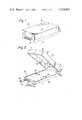
- FIG. 1is a perspective external view of an embodiment of the electronic device according to the present invention.
- FIG. 2is a perspective view of the device illustrated in FIG. 1, with the cover being partially opened;
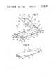
- FIG. 3is a perspective view of the cover illustrated in FIG. 2;
- FIG. 4is a perspective view of the printed circuit board unit illustrated in FIG. 2;
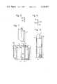
- FIG. 5is a cross sectional view taken through a part of the cover along the line 5--5 in FIG. 1;
- FIG. 6is a partial cross sectional view similar to FIG. 5, but illustrating another embodiment of the cover
- FIG. 7is a partially excluded perspective view illustrating a manner of setting the electronic device illustrated in FIG. 1 into a mounting chassis, and;
- FIG. 8is a partially excluded longitudinal cross sectional view taken along the line 8--8 in FIG. 7, illustrating the electronic device set in the mounting chassis.
- an electronic device designated generally by the reference numeral 10comprises a printed circuit board unit 11 and a cover 12.
- the printed circuit board unit 11includes a printed circuit board 13 on which a plurality of electronic elements (not shown) are mounted.
- the printed circuit board 13has integral portions 14 and 15 at the opposed ends, respectively.
- the end portion 14is provided with printed electrical terminals 16 so as to form an edge type electrical connector.
- the end portion 15is formed with a hole 17 therein so as to provide a handle which is used for insertion and removal of the electronic device 10 with respect to a mounting chassis, as will be described hereinafter.
- the printed circuit board unit 11is contained in or covered by the cover 12, with both the electrical connector 14 and the handle 15 being projected out of the cover, as illustrated in FIGS. 1 and 2.
- the cover 12is substantially rectangular parallelepiped in configuration in the assembled condition, as illustrated in FIG. 1, and is constructed from a single member of plastic material formed by moulding.
- the cover 12has an upper cover portion 21, a lower cover portion 22 and an end wall portion 23, which are integrally connected via flexible connecting portions 24 and 25.
- the end wall portion 23 and the flexible connecting portions 24 and 25serve as hinge means and permit pivotal movements of the upper and lower cover portions 21 and 22 with respect to each other, whereby the cover 12 can be opened and closed in the direction indicated by the arrow A in FIG. 3.
- the cover 12is made of a material which ensures high flexibility of the connecting portions 24 and 25, such as polypropylene or the like, for example.
- the upper cover portion 21has formed at its free edges two side walls 26 and 27, and an end wall 28, and; the lower cover portion 22 has formed at its free edges two side walls 29 and 30, and an end wall 31.
- the end wall 31 of the lower cover portion 22has a recess 32 formed on its upper edge, through which the electrical connector portion 14 of the printed circuit board unit 11 is projected out of the cover 12.
- the end wall portion 23is formed with a slit 33 therein, through which the handle 15 of the printed circuit board unit 11 is projected out of the cover 12.
- supporting seats 34On the insides of the respective side walls 29 and 30 of the lower cover portion 22, there are formed supporting seats 34, which have locking pins 35 projecting perpendicularly from the seat surfaces.
- supporting seats 36On the insides of the respective side walls 26 and 27, of the upper cover portion 21, there are formed supporting seats 36, which have holes 37 formed in the seat surfaces.
- the locking pins 35 and the holes 37are adapted for snap engagement with each other, so as to retain the upper and lower cover portions 21 and 22 in the closed position.
- the printed circuit board 13is formed with holes 18, through which the locking pins 35 pass loosely.
- the lower cover portion 22On the outside of the end wall 31 the lower cover portion 22 is provided with locking flaps 38, which are integrally connected to the end wall 31 via flexible hinge portions 39, and have locking pins 40 at the free end portion thereof.
- the hinge portions 39are adapted to permit the locking flaps 38 to be pivotally moved, in the direction indicated by an arrow B in FIG. 3, between the unlocking position illustrated by solid lines and the locking position illustrated by phantom lines, at which locking position the locking pins 40 are perpendicular to the locking pins 35.
- the upper cover portion 21has formed therein holes 41, which are adapted for snap engagement with the locking pins 40 so as to retain the upper and lower cover portions 21 and 22 in the closed position.
- the printed circuit board unit 11is initially put into the lower cover portion 22 of the cover 12, as illustrated in FIG. 2. This is effected by, firstly, inserting the handle 15 into the slit 33 so that the handle 15 projects beyond the end wall portion 23 and, then, putting the printed circuit board 13 on the supporting seats 34, with the locking pins 35 projecting through the holes 18, and also, with the electrical connector 14 being fitted in the recess 32 beyond the end wall 31. At this stage, the edges of three sides of the printed circuit board 13 abut against the insides of the side and end walls 29, 30 and 31, whereby the printed circuit board unit 11 is positioned in place.
- the locking flaps 38are turned up so as to bring the locking pins 40 into snap engagement with the holes 41 in the upper cover portion 21, as illustrated in FIG. 1, which completes the assembling. It will be appreciated that the direction of insertion of the locking pins 40 into the holes 41 is perpendicular to the direction of insertion of the locking pins 35 into the holes 37. This assures that the cover 12 is positively retained in the closed position against various external force.
- the upper and lower cover portions 21 and 22may have formed along partial adjoining lengths or the overall adjoining lengths of the side walls 26, 27, 29 and 30 additional locking portions, an example of which is illustrated in FIG. 6 by the reference numerals 26a and 29a. These locking portions interlock when the upper and lower cover portions are closed, thereby ensuring an even more positive retaining of the cover in the closed position than the above described embodiment.
- the cover 12is constructed from a single member, and can be easily and quickly assembled together with the printed circuit board unit in a one-touch locking manner without the use of fastening screws or the like.
- the assembled electronic device 10is set in a mounting chassis 50.
- the interior of the chassis 50is divided by partitions 51 into a plurality of compartments 52, in each of which the electronic device 10 is set with the electrical connector 14 of the electronic device 10 in engagement with an electrical connector 53 disposed at the bottom of the compartment 52, for providing the electrical connection for the printed circuit board unit 11.
- the outer walls of the cover 12slide along the inner wall of the compartment so as to guide the electrical connector 14 with respect to the corresponding connector 53, thereby ensuring a smooth engagement between them.
- the engagement and disengagement between the connectors 14 and 53is effected by using the handle 15.
- both the electrical connector 14 and the handle 15are integrally formed with the printed circuit board, the force applied to the handle 15 is transmitted via the printed circuit board to the connector 14, but is not applied to the cover 12. Accordingly, the engagement and disengagement of the electrical connector can be effected easily and accurately, and also, the cover can be made of a material having a low mechanical strength.
- the present inventionprovides an electronic device which is constructed from a minimum number of separate elements, which facilitates fabrication and assembly and accordingly, is simple in construction and inexpensive to manufacture.
Landscapes
- Engineering & Computer Science (AREA)
- Microelectronics & Electronic Packaging (AREA)
- Casings For Electric Apparatus (AREA)
- Mounting Of Printed Circuit Boards And The Like (AREA)
Abstract
Description
This invention relates to an electronic device having a printed circuit board unit therein and, in particular, to a device of the type in which the printed circuit board unit is contained in a cover, such as a repeater of a carrier transmission system, for example.
The electronic device of the type defined above is, when being used, set in a mounting chassis which is commonly installed in an underground hole, a shelter or the like. The printed circuit board unit is provided at one end of a printed circuit board with an electrical connector which is projected out of the cover. When the electronic device is inserted into the mounting chassis, the electrical connector of the electronic device is brought into engagement with the corresponding electrical connector disposed at the mounting chassis, thereby providing the electrical connection for the printed circuit board unit. The cover is adapted to also serve as a guide member when the electronic device is inserted into the mounting chassis, for ensuring a smooth engagement of the electrical connector. The cover is usually provided with a handle used for the engagement and disengagement of the electrical connector.
With the electronic device of the above defined type, various constructions are known. For example, a relatively convenient construction is disclosed in "Technical Manual Lynch 303RU01, 303RU02 Repeaters", produced by Lynch Communication System Inc., February 1977. However, even in this convenient construction, the cover is constructed from several separate elements which are assembled together with the printed circuit board unit by means of fastening screws. This construction is complicated, requires a large number of steps to fabricate and assemble and, accordingly, is expensive to manufacture.
It is, therefore, a primary object of the present invention to provide a new and improved electronic device of the above defined type which is relatively simple in construction and inexpensive to manufacture.
A specific object of the present invention is to provide an electronic device of the above defined type which is constructed from a minimum number of separate elements.
In a preferred form of the present invention, the cover is constructed from a member which is formed of a single piece of plastic material. This cover member has cover portions, flexible hinge portions for permitting the cover portions to be pivotally moved with respect to each other between open and closed positions of the cover, and locking portions adapted for retaining the cover portions in the closed position. The printed circuit board unit has a printed circuit board which is integrally formed with an electrical connector of edge type at one end and with a handle at the opposite end.
Such construction is relatively simple and minimizes the number of fabricating and assembling steps, thereby resulting in a low manufacturing cost.
The present invention will become more apparent from the following description of a preferred embodiment with reference to the accompanying drawings, in which:
FIG. 1 is a perspective external view of an embodiment of the electronic device according to the present invention;
FIG. 2 is a perspective view of the device illustrated in FIG. 1, with the cover being partially opened;
FIG. 3 is a perspective view of the cover illustrated in FIG. 2;
FIG. 4 is a perspective view of the printed circuit board unit illustrated in FIG. 2;
FIG. 5 is a cross sectional view taken through a part of the cover along theline 5--5 in FIG. 1;
FIG. 6 is a partial cross sectional view similar to FIG. 5, but illustrating another embodiment of the cover;
FIG. 7 is a partially excluded perspective view illustrating a manner of setting the electronic device illustrated in FIG. 1 into a mounting chassis, and;
FIG. 8 is a partially excluded longitudinal cross sectional view taken along theline 8--8 in FIG. 7, illustrating the electronic device set in the mounting chassis.
Referring to FIGS. 1 through 4, an electronic device designated generally by thereference numeral 10 comprises a printed circuit board unit 11 and acover 12. As best illustrated in FIG. 4, the printed circuit board unit 11 includes aprinted circuit board 13 on which a plurality of electronic elements (not shown) are mounted. The printedcircuit board 13 hasintegral portions end portion 14 is provided with printedelectrical terminals 16 so as to form an edge type electrical connector. Theend portion 15 is formed with ahole 17 therein so as to provide a handle which is used for insertion and removal of theelectronic device 10 with respect to a mounting chassis, as will be described hereinafter. The printed circuit board unit 11 is contained in or covered by thecover 12, with both theelectrical connector 14 and thehandle 15 being projected out of the cover, as illustrated in FIGS. 1 and 2.
Thecover 12 is substantially rectangular parallelepiped in configuration in the assembled condition, as illustrated in FIG. 1, and is constructed from a single member of plastic material formed by moulding. Thecover 12 has anupper cover portion 21, alower cover portion 22 and anend wall portion 23, which are integrally connected via flexible connectingportions end wall portion 23 and the flexible connectingportions lower cover portions cover 12 can be opened and closed in the direction indicated by the arrow A in FIG. 3. To this end, thecover 12 is made of a material which ensures high flexibility of the connectingportions
Theupper cover portion 21 has formed at its free edges twoside walls end wall 28, and; thelower cover portion 22 has formed at its free edges twoside walls end wall 31. When thecover 12 is in the closed position, thewalls walls
Theend wall 31 of thelower cover portion 22 has arecess 32 formed on its upper edge, through which theelectrical connector portion 14 of the printed circuit board unit 11 is projected out of thecover 12. On the other hand, theend wall portion 23 is formed with aslit 33 therein, through which thehandle 15 of the printed circuit board unit 11 is projected out of thecover 12.
On the insides of therespective side walls lower cover portion 22, there are formed supportingseats 34, which have lockingpins 35 projecting perpendicularly from the seat surfaces. On the other hand, on the insides of therespective side walls upper cover portion 21, there are formed supportingseats 36, which haveholes 37 formed in the seat surfaces. Thelocking pins 35 and theholes 37 are adapted for snap engagement with each other, so as to retain the upper andlower cover portions circuit board 13 is formed withholes 18, through which thelocking pins 35 pass loosely.
On the outside of theend wall 31 thelower cover portion 22 is provided withlocking flaps 38, which are integrally connected to theend wall 31 viaflexible hinge portions 39, and have lockingpins 40 at the free end portion thereof. Thehinge portions 39 are adapted to permit thelocking flaps 38 to be pivotally moved, in the direction indicated by an arrow B in FIG. 3, between the unlocking position illustrated by solid lines and the locking position illustrated by phantom lines, at which locking position thelocking pins 40 are perpendicular to thelocking pins 35. On the other hand, theupper cover portion 21 has formed thereinholes 41, which are adapted for snap engagement with thelocking pins 40 so as to retain the upper andlower cover portions
In assembling theelectronic device 10, the printed circuit board unit 11 is initially put into thelower cover portion 22 of thecover 12, as illustrated in FIG. 2. This is effected by, firstly, inserting thehandle 15 into theslit 33 so that thehandle 15 projects beyond theend wall portion 23 and, then, putting the printedcircuit board 13 on the supportingseats 34, with thelocking pins 35 projecting through theholes 18, and also, with theelectrical connector 14 being fitted in therecess 32 beyond theend wall 31. At this stage, the edges of three sides of the printedcircuit board 13 abut against the insides of the side andend walls
Subsequently, theupper cover portion 21 of thecover 12 is closed and, then, thelocking pins 35 and thecorresponding holes 37 are respectively brought into snap engagement with each other, whereby the printedcircuit board 13 is securely held between theseats lower cover portions
Finally, thelocking flaps 38 are turned up so as to bring thelocking pins 40 into snap engagement with theholes 41 in theupper cover portion 21, as illustrated in FIG. 1, which completes the assembling. It will be appreciated that the direction of insertion of thelocking pins 40 into theholes 41 is perpendicular to the direction of insertion of thelocking pins 35 into theholes 37. This assures that thecover 12 is positively retained in the closed position against various external force.
Furthermore, the upper andlower cover portions side walls reference numerals 26a and 29a. These locking portions interlock when the upper and lower cover portions are closed, thereby ensuring an even more positive retaining of the cover in the closed position than the above described embodiment.
As will be apparent from the above description, thecover 12 is constructed from a single member, and can be easily and quickly assembled together with the printed circuit board unit in a one-touch locking manner without the use of fastening screws or the like.
Referring to FIGS. 7 and 8, the assembledelectronic device 10 is set in amounting chassis 50. The interior of thechassis 50 is divided bypartitions 51 into a plurality ofcompartments 52, in each of which theelectronic device 10 is set with theelectrical connector 14 of theelectronic device 10 in engagement with anelectrical connector 53 disposed at the bottom of thecompartment 52, for providing the electrical connection for the printed circuit board unit 11. When theelectronic device 10 is inserted into thecompartment 52, the outer walls of thecover 12 slide along the inner wall of the compartment so as to guide theelectrical connector 14 with respect to thecorresponding connector 53, thereby ensuring a smooth engagement between them. The engagement and disengagement between theconnectors handle 15. In this case, since both theelectrical connector 14 and thehandle 15 are integrally formed with the printed circuit board, the force applied to thehandle 15 is transmitted via the printed circuit board to theconnector 14, but is not applied to thecover 12. Accordingly, the engagement and disengagement of the electrical connector can be effected easily and accurately, and also, the cover can be made of a material having a low mechanical strength.
It will be appreciated from the above description that the present invention provides an electronic device which is constructed from a minimum number of separate elements, which facilitates fabrication and assembly and accordingly, is simple in construction and inexpensive to manufacture.
The invention has been described in detail with particular reference to preferred embodiments thereof, but it will be appreciated that various variations and modifications can be effected within the spirit and scope of the invention.
Claims (8)
1. An electronic device for use in a communication system unit, said unit including a mounting chassis having a plurality of compartments, each compartment comprising means for receiving said electronic device and an electrical connector for making electrical connection thereto, said electronic device comprising:
a printed circuit board unit including a printed circuit board, said board being provided at one end with an integral electrical connector for engagement with said electrical connector of a respective one of said chassis compartments and at the opposite end with an integral handle for use for the insertion and removal of the electronic device into and from the chassis, and
cover means for containing said printed circuit board unit with said electrical connector and said handle projecting out from said cover means, said cover means being adapted to serve as guide means for insertion of the electronic device into the respective mounting chassis compartment and for positioning said circuit board within said cover means, said cover means being constructed from a single member, said single member comprising
first and second cover portions,
flexible hinge means for permitting said cover portions to be pivotally moved with respect to each other between open and closed positions of said cover means,
supporting seats formed on the inside of said cover portions for securely holding said printed circuit board unit when said cover means is in the closed position, and
locking means for retaining said cover means in the closed position, said locking means comprises a locking pin formed on the supporting seats on one of said cover portions, each said locking pin being adapted to pass through a hole formed in the printed circuit board for snap engagement with a hole formed in the other supporting seat on the other of said cover portions when said cover means is in the closed position.
2. An electronic device according to claim 1, said locking means further comprising a locking flap formed on the outside of a first one of said cover portions and having a flexible hinge portion and a second locking pin, said flexible hinge portion being adapted to permit said locking flap to be pivotally moved with respect to said first cover portion between a locked position of said locking flap, in which locked position said second locking pin is in snap engagement with a second hole formed in the outside of the other of said cover portions when said cover means is in the closed position, and an unlocked position of said locking flap, the direction in which said locking pin on the supporting seat engages the corresponding hole being perpendicular to the direction in which said second locking pin of the locking flap engages said second hole.
3. An electronic device according to claim 1 or 2, said locking means comprising interlocking portions formed selectively along respective adjoining edges of said first and second cover portions.
4. An electronic device according to claim 1 said electrical connector being of the edge type.
5. An electronic device according to claim 1, said handle being constructed from an integral end portion of said printed circuit board and having a hole therein.
6. An electronic device according to claim 1, said cover member comprising moulded plastic material.
7. The device of claim 1, said cover member comprising polypropylene.
8. The device of claim 1, said cover means for positioning said circuit board comprising said locking pins passing through said holes in said circuit board in said closed position of said cover means.
Applications Claiming Priority (2)
| Application Number | Priority Date | Filing Date | Title |
|---|---|---|---|
| JP1978058960UJPS5818299Y2 (en) | 1978-04-28 | 1978-04-28 | Electronic equipment with built-in printed circuit board unit |
| JP53/58960[U] | 1978-04-28 |
Publications (1)
| Publication Number | Publication Date |
|---|---|
| US4226491Atrue US4226491A (en) | 1980-10-07 |
Family
ID=13099398
Family Applications (1)
| Application Number | Title | Priority Date | Filing Date |
|---|---|---|---|
| US06/033,896Expired - LifetimeUS4226491A (en) | 1978-04-28 | 1979-04-27 | Electronic device having a printed circuit board unit therein |
Country Status (2)
| Country | Link |
|---|---|
| US (1) | US4226491A (en) |
| JP (1) | JPS5818299Y2 (en) |
Cited By (99)
| Publication number | Priority date | Publication date | Assignee | Title |
|---|---|---|---|---|
| US4358178A (en)* | 1981-01-05 | 1982-11-09 | Western Electric Company, Inc. | Hood for multicontact connector |
| US4391532A (en)* | 1980-04-22 | 1983-07-05 | Kabushiki Kaisha Daini Seikosha | Electromagnetic acoustic transducer |
| US4394707A (en)* | 1981-02-26 | 1983-07-19 | Bell Telephone Laboratories, Incorporated | Electrical circuit package |
| US4398236A (en)* | 1981-03-02 | 1983-08-09 | Zenith Radio Corporation | PC Board mounting apparatus |
| US4477862A (en)* | 1982-05-19 | 1984-10-16 | Gould Inc. | Backplane connector |
| EP0122974A1 (en)* | 1983-03-30 | 1984-10-31 | International Business Machines Corporation | Electronic component assembly comprising a printed circuit board unit and cover therefor |
| US4513354A (en)* | 1983-09-26 | 1985-04-23 | Sentrol, Inc. | Housing for an electronic circuit board |
| USRE31929E (en)* | 1980-07-18 | 1985-06-25 | Thomas & Betts Corporation | Electronic package and accessory component assembly |
| DE3411776A1 (en)* | 1984-03-30 | 1985-10-10 | Standard Elektrik Lorenz Ag, 7000 Stuttgart | Method for producing an insertion head, and an insertion head which is produced in accordance with this method, for apparatus inserts used in telecommunications |
| FR2572239A1 (en)* | 1984-10-19 | 1986-04-25 | Burr Brown Corp | HOUSING FOR EXTENSIBLE REMOTE INTERFACE TELEPHONE SYSTEMS |
| US4591950A (en)* | 1983-09-09 | 1986-05-27 | American Manufacturing Company, Inc. | Circuit board-terminal-housing assembly |
| DE3515772A1 (en)* | 1985-05-02 | 1986-11-06 | Robert Bosch Gmbh, 7000 Stuttgart | Housing consisting of two housing half shells |
| US4636920A (en)* | 1985-09-05 | 1987-01-13 | Caterpillar Inc. | Printed circuit board mounting apparatus |
| US4700272A (en)* | 1986-06-26 | 1987-10-13 | Digital Equipment Corporation | Apparatus and method for compensation of thermal expansion of cooling fluid in enclosed electronic packages |
| US4719696A (en)* | 1984-10-19 | 1988-01-19 | Burr-Brown Corporation | Package for an expandable remote interface unit |
| WO1988008662A1 (en)* | 1987-04-24 | 1988-11-03 | Racal Data Communications Inc. | Modular expandable housing arrangement for electronic apparatus |
| DE3813888A1 (en)* | 1988-04-20 | 1989-11-02 | Schleicher Elektronic Gmbh & C | MODULE FOR A CONTROLLER CONSTRUCTED FROM SEVERAL MODULES SIT ON A CARRIER |
| US4893001A (en)* | 1986-01-20 | 1990-01-09 | Itt Corporation | IC card |
| US4942380A (en)* | 1989-01-23 | 1990-07-17 | Motorola, Inc. | Housing assembly having flexible shield and insulator |
| US4945633A (en)* | 1989-03-01 | 1990-08-07 | Nokia-Mobira Oy | Method of mounting a printed circuit board and securing the earthing to a casing |
| US4966562A (en)* | 1988-09-06 | 1990-10-30 | The Ohio Bell Telephone Company | Single slot repeater mounting |
| US4986778A (en)* | 1989-05-04 | 1991-01-22 | 501 Venturdyne, Ltd. | Carrier for use in testing circuit boards |
| US5099391A (en)* | 1990-12-28 | 1992-03-24 | Square D Company | Housing for a rack mountable power supply for use with a programmable logic controller |
| US5106322A (en)* | 1988-07-13 | 1992-04-21 | Bull S.A. | Electrical computer connection system |
| US5156556A (en)* | 1991-03-13 | 1992-10-20 | Ma Hsi K | Office automation unit |
| DE4137687A1 (en)* | 1991-10-18 | 1993-04-22 | Vero Electronics Gmbh | Cassette for receiving circuit board - is mfr. as one piece with folding operation carried out to form open ended box cassette |
| US5243461A (en)* | 1992-01-02 | 1993-09-07 | Jiann Shyan Tsyan | Bicycle signalling assembly |
| US5242310A (en)* | 1992-06-19 | 1993-09-07 | Data Trek Corporation | PC I/O card |
| US5262923A (en)* | 1991-06-21 | 1993-11-16 | Tandon Corporation | Railing with grounding tabs for grounding and mounting computer components in a computer |
| US5276278A (en)* | 1993-03-09 | 1994-01-04 | Lin Min Huei | Housing of ceiling fan control circuit board |
| US5278445A (en)* | 1989-09-27 | 1994-01-11 | Mitsubishi Denki Kabushiki Kaisha | Semiconductor device card having a plurality of self-locking pawls |
| DE4232048A1 (en)* | 1992-09-24 | 1994-03-31 | Siemens Ag | Electronic controller with circuit board in housing - has inner chamber formed by two identical parts and plug-in component in between |
| US5373104A (en)* | 1993-07-12 | 1994-12-13 | Delco Electronics Corporation | Control module with integral fastening/locking assembly |
| US5446622A (en)* | 1993-08-06 | 1995-08-29 | Digital Equipment Corporation | PC board cartridge for a computer terminal |
| US5461543A (en)* | 1992-09-28 | 1995-10-24 | Hitachi Telecom Technologies Ltd. | Electric appliance, its assembling method, and its housing structure |
| US5477421A (en)* | 1993-11-18 | 1995-12-19 | Itt Corporation | Shielded IC card |
| USD369588S (en) | 1994-11-04 | 1996-05-07 | Metropage, Inc. | Heat seal connector for a pager |
| USD370464S (en) | 1994-11-30 | 1996-06-04 | Metropage, Inc. | Heat seal connector for a pager |
| US5581446A (en)* | 1992-09-28 | 1996-12-03 | Hitachi Telecom Technologies Ltd. | Housing structure of electric appliance and disassembling method thereof |
| DE19639889A1 (en)* | 1996-09-27 | 1998-04-02 | Siemens Ag | Electrical equipment housing |
| US5740019A (en)* | 1994-09-06 | 1998-04-14 | Samsung Electronics Co., Ltd. | Apparatus for mounting a printed circuit board in a monitor case |
| US5856910A (en)* | 1996-10-30 | 1999-01-05 | Intel Corporation | Processor card assembly having a cover with flexible locking latches |
| US5873751A (en)* | 1995-12-07 | 1999-02-23 | Methode Electronics, Inc. | Circuitized insulator |
| US5879173A (en)* | 1995-01-13 | 1999-03-09 | Methode Electronics, Inc. | Removable transceiver module and receptacle |
| US5892663A (en)* | 1997-06-03 | 1999-04-06 | International Business Machines Corporation | Flexible insulator for telecommunications network printed |
| US5923026A (en)* | 1996-12-11 | 1999-07-13 | Mitsubishi Denki Kabushiki Kaisha | Assembly structure for an IC card |
| US6028771A (en)* | 1998-11-11 | 2000-02-22 | Intel Corporation | Cover for an electronic cartridge |
| USRE36820E (en)* | 1995-01-13 | 2000-08-15 | Methode Electronics, Inc. | Removable optoelectronic module |
| WO2000076283A1 (en)* | 1999-06-03 | 2000-12-14 | Telefonaktiebolaget Lm Ericsson (Publ) | Encapsulation of printed circuit board |
| US6179627B1 (en) | 1998-04-22 | 2001-01-30 | Stratos Lightwave, Inc. | High speed interface converter module |
| US6201709B1 (en)* | 1999-03-05 | 2001-03-13 | Leviton Manufacturing Co., Inc. | Mounting system to support electrical components in a stacked relationship to one another |
| US6201704B1 (en) | 1995-01-13 | 2001-03-13 | Stratos Lightwave, Inc. | Transceive module with EMI shielding |
| US6203333B1 (en) | 1998-04-22 | 2001-03-20 | Stratos Lightwave, Inc. | High speed interface converter module |
| US6215673B1 (en)* | 1999-08-27 | 2001-04-10 | Intel Corporation | Hot plug PCI retainer and actuator |
| US6220878B1 (en) | 1995-10-04 | 2001-04-24 | Methode Electronics, Inc. | Optoelectronic module with grounding means |
| US6220873B1 (en)* | 1999-08-10 | 2001-04-24 | Stratos Lightwave, Inc. | Modified contact traces for interface converter |
| WO2001062056A1 (en)* | 2000-02-15 | 2001-08-23 | Bitmicro Networks, Inc. | Printed circuit board assembly |
| US6454580B1 (en)* | 2001-08-22 | 2002-09-24 | Hon Hai Precision Ind. Co., Ltd. | Guide rail for receiving a GBIC module |
| US20020150353A1 (en)* | 2001-04-14 | 2002-10-17 | Chiu Liew Chuang | Method and apparatus for push button release fiber optic modules |
| US20020150343A1 (en)* | 2001-04-14 | 2002-10-17 | Chiu Liew C. | De-latching mechanisms for fiber optic modules |
| US6504724B2 (en)* | 2000-10-31 | 2003-01-07 | Yazaki Corporation | Structure of drawing out flexible circuit member |
| US6527188B1 (en)* | 1998-04-14 | 2003-03-04 | J. S. T. Mfg. Co., Ltd | Frame kit for PC card, PC card, and method of manufacturing PC Card |
| US20030096524A1 (en)* | 1998-08-20 | 2003-05-22 | Llapitan David J. | Retention mechanism for an electrical assembly |
| US6607308B2 (en) | 2001-02-12 | 2003-08-19 | E20 Communications, Inc. | Fiber-optic modules with shielded housing/covers having mixed finger types |
| US6659655B2 (en) | 2001-02-12 | 2003-12-09 | E20 Communications, Inc. | Fiber-optic modules with housing/shielding |
| US6796715B2 (en) | 2001-04-14 | 2004-09-28 | E20 Communications, Inc. | Fiber optic modules with pull-action de-latching mechanisms |
| US20040190275A1 (en)* | 2000-10-18 | 2004-09-30 | Roscoe Brett D. | System for protecting electronic components |
| US6840680B1 (en) | 2001-04-14 | 2005-01-11 | Jds Uniphase Corporation | Retention and release mechanisms for fiber optic modules |
| US6851867B2 (en) | 2001-04-14 | 2005-02-08 | Jds Uniphase Corporation | Cam-follower release mechanism for fiber optic modules with side delatching mechanisms |
| US20050048850A1 (en)* | 2003-08-29 | 2005-03-03 | Hirschmann Electronics Gmbh & Co. Kg | Sandwich housing for an antenna amplifier |
| US20050148944A1 (en)* | 2003-12-24 | 2005-07-07 | Hsin-Po Hsieh | Syringe safety sleeve |
| US6942395B1 (en) | 2001-01-29 | 2005-09-13 | Jds Uniphase Corporation | Method and apparatus of pull-lever release for fiber optic modules |
| US6994478B1 (en) | 2001-04-14 | 2006-02-07 | Jds Uniphase Corporation | Modules having rotatable release and removal lever |
| US7090509B1 (en) | 1999-06-11 | 2006-08-15 | Stratos International, Inc. | Multi-port pluggable transceiver (MPPT) with multiple LC duplex optical receptacles |
| US7118281B2 (en) | 2002-08-09 | 2006-10-10 | Jds Uniphase Corporation | Retention and release mechanisms for fiber optic modules |
| US20070236905A1 (en)* | 2006-03-28 | 2007-10-11 | Inventec Corporation | Fixing structure of circuit board |
| USRE40150E1 (en) | 1994-04-25 | 2008-03-11 | Matsushita Electric Industrial Co., Ltd. | Fiber optic module |
| US20080077290A1 (en)* | 2006-09-25 | 2008-03-27 | Robert Vincent Weinmann | Fleet operations quality management system |
| US20080074854A1 (en)* | 2006-09-25 | 2008-03-27 | Barry Douglas Batcheller | Crash-hardened memory device and method of creating the same |
| US20080134349A1 (en)* | 2006-11-30 | 2008-06-05 | Honeywell International Inc. | Card slot anti-tamper protection system |
| US20080234936A1 (en)* | 2006-09-25 | 2008-09-25 | Robert Vincent Weinmann | Method for resolving ground level errors in simulations |
| US20090200489A1 (en)* | 2005-10-28 | 2009-08-13 | Fei Company | Hermetically sealed housing with electrical feed-in |
| US20100073901A1 (en)* | 2008-09-22 | 2010-03-25 | Fujitsu Limited | Electronic device |
| WO2010102894A1 (en)* | 2009-03-13 | 2010-09-16 | Osram Gesellschaft mit beschränkter Haftung | Casing for electronic ballast |
| DE102009048527A1 (en)* | 2009-10-07 | 2011-04-14 | Conti Temic Microelectronic Gmbh | Arrangement for connecting multiple interconnect devices by frame, has frame that has receiving frame part and fixing frame part, where both frame parts are connected with each other by flexible connecting unit |
| US20110171612A1 (en)* | 2005-07-22 | 2011-07-14 | Gelinske Joshua N | Synchronized video and synthetic visualization system and method |
| US8081921B2 (en) | 2005-07-22 | 2011-12-20 | Appareo Systems, Llc | Flight training and synthetic visualization system and method |
| US20110310574A1 (en)* | 2010-06-17 | 2011-12-22 | Denso Corporation | Electronic control unit for vehicle |
| US20120020038A1 (en)* | 2010-01-29 | 2012-01-26 | Fujitsu Limited | Electronic apparatus and method related thereto |
| US9047717B2 (en) | 2006-09-25 | 2015-06-02 | Appareo Systems, Llc | Fleet operations quality management system and automatic multi-generational data caching and recovery |
| US9172481B2 (en) | 2012-07-20 | 2015-10-27 | Appareo Systems, Llc | Automatic multi-generational data caching and recovery |
| US9202318B2 (en) | 2006-09-25 | 2015-12-01 | Appareo Systems, Llc | Ground fleet operations quality management system |
| US20170237204A1 (en)* | 2016-02-12 | 2017-08-17 | Jtekt Corporation | Circuit Board Assembly And Method Of Manufacturing The Same |
| EP2398306A3 (en)* | 2010-06-17 | 2017-11-08 | Seiko Epson Corporation | Board module and printer |
| US9972930B1 (en) | 2017-01-16 | 2018-05-15 | Methode Electronics, Inc. | Transceiver module wit flex circuit |
| US11089703B2 (en) | 2020-01-10 | 2021-08-10 | Chicony Power Technology Co., Ltd. | Power converter |
| US11177594B2 (en)* | 2020-04-09 | 2021-11-16 | Ii-Vi Delaware, Inc. | Housing for pluggable module |
| US11440605B2 (en)* | 2018-03-07 | 2022-09-13 | Honda Motor Co., Ltd. | Control unit arrangement structure for saddle riding-type vehicle |
| US20230148133A1 (en)* | 2021-11-09 | 2023-05-11 | Haier Us Appliance Solutions, Inc. | Domestic appliance and one-piece modular housing therefor |
Citations (8)
| Publication number | Priority date | Publication date | Assignee | Title |
|---|---|---|---|---|
| US2976510A (en)* | 1957-05-02 | 1961-03-21 | Sperry Rand Corp | Wrench for printed circuit card library rack |
| US3641482A (en)* | 1969-07-01 | 1972-02-08 | Kabel Metallwerke Ghh | Plug connector for flat conductor strip line |
| US3668476A (en)* | 1970-09-11 | 1972-06-06 | Seeburg Corp | Self-locking enclosure for electronic circuitry and method of assembling the same |
| US3825110A (en)* | 1972-07-14 | 1974-07-23 | F Halbich | Plastic case for glasses |
| US3937946A (en)* | 1974-03-06 | 1976-02-10 | General Electric Company | Multiple flash lamp unit |
| US4011940A (en)* | 1975-12-12 | 1977-03-15 | Amaray International Corporation | Hinged storage container for tape cartridge with self-aligning walls |
| US4030850A (en)* | 1976-08-02 | 1977-06-21 | The United States Of America As Represented By The Secretary Of The Army | Interlocked joint |
| US4138711A (en)* | 1977-09-29 | 1979-02-06 | Allen-Bradley Company | Static control device for printed circuit package |
Family Cites Families (2)
| Publication number | Priority date | Publication date | Assignee | Title |
|---|---|---|---|---|
| JPS4317685Y1 (en)* | 1965-10-29 | 1968-07-23 | ||
| JPS5150619Y2 (en)* | 1971-10-30 | 1976-12-04 |
- 1978
- 1978-04-28JPJP1978058960Upatent/JPS5818299Y2/ennot_activeExpired
- 1979
- 1979-04-27USUS06/033,896patent/US4226491A/ennot_activeExpired - Lifetime
Patent Citations (8)
| Publication number | Priority date | Publication date | Assignee | Title |
|---|---|---|---|---|
| US2976510A (en)* | 1957-05-02 | 1961-03-21 | Sperry Rand Corp | Wrench for printed circuit card library rack |
| US3641482A (en)* | 1969-07-01 | 1972-02-08 | Kabel Metallwerke Ghh | Plug connector for flat conductor strip line |
| US3668476A (en)* | 1970-09-11 | 1972-06-06 | Seeburg Corp | Self-locking enclosure for electronic circuitry and method of assembling the same |
| US3825110A (en)* | 1972-07-14 | 1974-07-23 | F Halbich | Plastic case for glasses |
| US3937946A (en)* | 1974-03-06 | 1976-02-10 | General Electric Company | Multiple flash lamp unit |
| US4011940A (en)* | 1975-12-12 | 1977-03-15 | Amaray International Corporation | Hinged storage container for tape cartridge with self-aligning walls |
| US4030850A (en)* | 1976-08-02 | 1977-06-21 | The United States Of America As Represented By The Secretary Of The Army | Interlocked joint |
| US4138711A (en)* | 1977-09-29 | 1979-02-06 | Allen-Bradley Company | Static control device for printed circuit package |
Cited By (152)
| Publication number | Priority date | Publication date | Assignee | Title |
|---|---|---|---|---|
| US4391532A (en)* | 1980-04-22 | 1983-07-05 | Kabushiki Kaisha Daini Seikosha | Electromagnetic acoustic transducer |
| USRE31929E (en)* | 1980-07-18 | 1985-06-25 | Thomas & Betts Corporation | Electronic package and accessory component assembly |
| US4358178A (en)* | 1981-01-05 | 1982-11-09 | Western Electric Company, Inc. | Hood for multicontact connector |
| US4394707A (en)* | 1981-02-26 | 1983-07-19 | Bell Telephone Laboratories, Incorporated | Electrical circuit package |
| US4398236A (en)* | 1981-03-02 | 1983-08-09 | Zenith Radio Corporation | PC Board mounting apparatus |
| US4477862A (en)* | 1982-05-19 | 1984-10-16 | Gould Inc. | Backplane connector |
| US4499523A (en)* | 1983-03-30 | 1985-02-12 | International Business Machines Corporation | Electronic component assembly with a printed circuit board unit and cover |
| EP0122974A1 (en)* | 1983-03-30 | 1984-10-31 | International Business Machines Corporation | Electronic component assembly comprising a printed circuit board unit and cover therefor |
| US4591950A (en)* | 1983-09-09 | 1986-05-27 | American Manufacturing Company, Inc. | Circuit board-terminal-housing assembly |
| US4513354A (en)* | 1983-09-26 | 1985-04-23 | Sentrol, Inc. | Housing for an electronic circuit board |
| DE3411776A1 (en)* | 1984-03-30 | 1985-10-10 | Standard Elektrik Lorenz Ag, 7000 Stuttgart | Method for producing an insertion head, and an insertion head which is produced in accordance with this method, for apparatus inserts used in telecommunications |
| FR2572239A1 (en)* | 1984-10-19 | 1986-04-25 | Burr Brown Corp | HOUSING FOR EXTENSIBLE REMOTE INTERFACE TELEPHONE SYSTEMS |
| US4672510A (en)* | 1984-10-19 | 1987-06-09 | Burr-Brown Corporation | Package for an expandable remote interface unit |
| US4719696A (en)* | 1984-10-19 | 1988-01-19 | Burr-Brown Corporation | Package for an expandable remote interface unit |
| DE3515772A1 (en)* | 1985-05-02 | 1986-11-06 | Robert Bosch Gmbh, 7000 Stuttgart | Housing consisting of two housing half shells |
| US4636920A (en)* | 1985-09-05 | 1987-01-13 | Caterpillar Inc. | Printed circuit board mounting apparatus |
| US4893001A (en)* | 1986-01-20 | 1990-01-09 | Itt Corporation | IC card |
| US4909742A (en)* | 1986-01-20 | 1990-03-20 | Itt Corporation | IC card and mating socket |
| US4700272A (en)* | 1986-06-26 | 1987-10-13 | Digital Equipment Corporation | Apparatus and method for compensation of thermal expansion of cooling fluid in enclosed electronic packages |
| GB2235592B (en)* | 1987-04-24 | 1991-10-23 | Racal Data Communications Inc | Modular expandable housing arrangement for electronic apparatus |
| US4858070A (en)* | 1987-04-24 | 1989-08-15 | Racal Data Communications Inc. | Modular expandable housing arrangement for electronic apparatus |
| WO1988008662A1 (en)* | 1987-04-24 | 1988-11-03 | Racal Data Communications Inc. | Modular expandable housing arrangement for electronic apparatus |
| GB2235592A (en)* | 1987-04-24 | 1991-03-06 | Racal Data Communications Inc | Modular expandable housing arrangement for electronic apparatus |
| DE3813888A1 (en)* | 1988-04-20 | 1989-11-02 | Schleicher Elektronic Gmbh & C | MODULE FOR A CONTROLLER CONSTRUCTED FROM SEVERAL MODULES SIT ON A CARRIER |
| US5032951A (en)* | 1988-04-20 | 1991-07-16 | Schleicher Electronic Gmbh & Co. Kg. | Module for a control system comprising several modules juxtaposed on a carrier |
| US5106322A (en)* | 1988-07-13 | 1992-04-21 | Bull S.A. | Electrical computer connection system |
| US4966562A (en)* | 1988-09-06 | 1990-10-30 | The Ohio Bell Telephone Company | Single slot repeater mounting |
| US4942380A (en)* | 1989-01-23 | 1990-07-17 | Motorola, Inc. | Housing assembly having flexible shield and insulator |
| US4945633A (en)* | 1989-03-01 | 1990-08-07 | Nokia-Mobira Oy | Method of mounting a printed circuit board and securing the earthing to a casing |
| US4986778A (en)* | 1989-05-04 | 1991-01-22 | 501 Venturdyne, Ltd. | Carrier for use in testing circuit boards |
| US5278445A (en)* | 1989-09-27 | 1994-01-11 | Mitsubishi Denki Kabushiki Kaisha | Semiconductor device card having a plurality of self-locking pawls |
| US5099391A (en)* | 1990-12-28 | 1992-03-24 | Square D Company | Housing for a rack mountable power supply for use with a programmable logic controller |
| US5156556A (en)* | 1991-03-13 | 1992-10-20 | Ma Hsi K | Office automation unit |
| US5262923A (en)* | 1991-06-21 | 1993-11-16 | Tandon Corporation | Railing with grounding tabs for grounding and mounting computer components in a computer |
| DE4137687A1 (en)* | 1991-10-18 | 1993-04-22 | Vero Electronics Gmbh | Cassette for receiving circuit board - is mfr. as one piece with folding operation carried out to form open ended box cassette |
| US5243461A (en)* | 1992-01-02 | 1993-09-07 | Jiann Shyan Tsyan | Bicycle signalling assembly |
| US5594625A (en)* | 1992-02-28 | 1997-01-14 | Hitachi Telecom Technologies Ltd. | Electric appliance, its assembling method, and its housing structure |
| US5242310A (en)* | 1992-06-19 | 1993-09-07 | Data Trek Corporation | PC I/O card |
| US5473509A (en)* | 1992-09-24 | 1995-12-05 | Siemens Aktiengesellschaft | Electronic control unit |
| DE4232048A1 (en)* | 1992-09-24 | 1994-03-31 | Siemens Ag | Electronic controller with circuit board in housing - has inner chamber formed by two identical parts and plug-in component in between |
| US5671122A (en)* | 1992-09-24 | 1997-09-23 | Siemens Akitiengesellschaft | Electronic control unit |
| US5461543A (en)* | 1992-09-28 | 1995-10-24 | Hitachi Telecom Technologies Ltd. | Electric appliance, its assembling method, and its housing structure |
| US5838402A (en)* | 1992-09-28 | 1998-11-17 | Hitachi Telecom Technologies, Ltd. | Electric appliance, its assembling method, and its housing structure |
| US5581446A (en)* | 1992-09-28 | 1996-12-03 | Hitachi Telecom Technologies Ltd. | Housing structure of electric appliance and disassembling method thereof |
| US5602722A (en)* | 1992-09-28 | 1997-02-11 | Hitachi Telecom Technologies, Ltd. | Electric appliance, its assembling method, and its housing structure |
| US5276278A (en)* | 1993-03-09 | 1994-01-04 | Lin Min Huei | Housing of ceiling fan control circuit board |
| US5373104A (en)* | 1993-07-12 | 1994-12-13 | Delco Electronics Corporation | Control module with integral fastening/locking assembly |
| US5446622A (en)* | 1993-08-06 | 1995-08-29 | Digital Equipment Corporation | PC board cartridge for a computer terminal |
| US5477421A (en)* | 1993-11-18 | 1995-12-19 | Itt Corporation | Shielded IC card |
| USRE40154E1 (en) | 1994-04-25 | 2008-03-18 | Matsushita Electric Industrial Co., Ltd. | Fiber optic module |
| USRE40150E1 (en) | 1994-04-25 | 2008-03-11 | Matsushita Electric Industrial Co., Ltd. | Fiber optic module |
| US5740019A (en)* | 1994-09-06 | 1998-04-14 | Samsung Electronics Co., Ltd. | Apparatus for mounting a printed circuit board in a monitor case |
| USD369588S (en) | 1994-11-04 | 1996-05-07 | Metropage, Inc. | Heat seal connector for a pager |
| USD370464S (en) | 1994-11-30 | 1996-06-04 | Metropage, Inc. | Heat seal connector for a pager |
| USRE36820E (en)* | 1995-01-13 | 2000-08-15 | Methode Electronics, Inc. | Removable optoelectronic module |
| US5879173A (en)* | 1995-01-13 | 1999-03-09 | Methode Electronics, Inc. | Removable transceiver module and receptacle |
| US6267606B1 (en) | 1995-01-13 | 2001-07-31 | Stratos Lightwave, Inc. | Removable transceiver module and receptacle |
| US6201704B1 (en) | 1995-01-13 | 2001-03-13 | Stratos Lightwave, Inc. | Transceive module with EMI shielding |
| US6220878B1 (en) | 1995-10-04 | 2001-04-24 | Methode Electronics, Inc. | Optoelectronic module with grounding means |
| US5873751A (en)* | 1995-12-07 | 1999-02-23 | Methode Electronics, Inc. | Circuitized insulator |
| DE19639889C2 (en)* | 1996-09-27 | 2000-01-05 | Siemens Ag | Housing for receiving electrical equipment |
| DE19639889A1 (en)* | 1996-09-27 | 1998-04-02 | Siemens Ag | Electrical equipment housing |
| US5856910A (en)* | 1996-10-30 | 1999-01-05 | Intel Corporation | Processor card assembly having a cover with flexible locking latches |
| US5923026A (en)* | 1996-12-11 | 1999-07-13 | Mitsubishi Denki Kabushiki Kaisha | Assembly structure for an IC card |
| US5892663A (en)* | 1997-06-03 | 1999-04-06 | International Business Machines Corporation | Flexible insulator for telecommunications network printed |
| US6527188B1 (en)* | 1998-04-14 | 2003-03-04 | J. S. T. Mfg. Co., Ltd | Frame kit for PC card, PC card, and method of manufacturing PC Card |
| US6179627B1 (en) | 1998-04-22 | 2001-01-30 | Stratos Lightwave, Inc. | High speed interface converter module |
| US6203333B1 (en) | 1998-04-22 | 2001-03-20 | Stratos Lightwave, Inc. | High speed interface converter module |
| US6585534B2 (en) | 1998-08-20 | 2003-07-01 | Intel Corporation | Retention mechanism for an electrical assembly |
| US20030096524A1 (en)* | 1998-08-20 | 2003-05-22 | Llapitan David J. | Retention mechanism for an electrical assembly |
| US6722908B2 (en) | 1998-08-20 | 2004-04-20 | Intel Corporation | Retention mechanism for an electrical assembly |
| WO2000028801A1 (en)* | 1998-11-11 | 2000-05-18 | Intel Corporation | A cover for an electronic cartridge |
| US6028771A (en)* | 1998-11-11 | 2000-02-22 | Intel Corporation | Cover for an electronic cartridge |
| US6201709B1 (en)* | 1999-03-05 | 2001-03-13 | Leviton Manufacturing Co., Inc. | Mounting system to support electrical components in a stacked relationship to one another |
| WO2000076283A1 (en)* | 1999-06-03 | 2000-12-14 | Telefonaktiebolaget Lm Ericsson (Publ) | Encapsulation of printed circuit board |
| US7090509B1 (en) | 1999-06-11 | 2006-08-15 | Stratos International, Inc. | Multi-port pluggable transceiver (MPPT) with multiple LC duplex optical receptacles |
| US6220873B1 (en)* | 1999-08-10 | 2001-04-24 | Stratos Lightwave, Inc. | Modified contact traces for interface converter |
| US6215673B1 (en)* | 1999-08-27 | 2001-04-10 | Intel Corporation | Hot plug PCI retainer and actuator |
| US6317330B1 (en)* | 2000-02-15 | 2001-11-13 | Bitmicro Networks, Inc. | Printed circuit board assembly |
| WO2001062056A1 (en)* | 2000-02-15 | 2001-08-23 | Bitmicro Networks, Inc. | Printed circuit board assembly |
| US7057901B2 (en)* | 2000-10-18 | 2006-06-06 | Hewlett-Packard Development Company, L.P. | System for protecting electronic components |
| US7057900B2 (en)* | 2000-10-18 | 2006-06-06 | Hewlett-Packard Development Company, L.P. | System for protecting electronic components |
| US20040212967A1 (en)* | 2000-10-18 | 2004-10-28 | Roscoe Brett D. | System for protecting electronic components |
| US20040190275A1 (en)* | 2000-10-18 | 2004-09-30 | Roscoe Brett D. | System for protecting electronic components |
| US6504724B2 (en)* | 2000-10-31 | 2003-01-07 | Yazaki Corporation | Structure of drawing out flexible circuit member |
| US6942395B1 (en) | 2001-01-29 | 2005-09-13 | Jds Uniphase Corporation | Method and apparatus of pull-lever release for fiber optic modules |
| US6874953B2 (en) | 2001-02-12 | 2005-04-05 | Jds Uniphase Corporation | Methods and apparatus for fiber-optic modules with shielded housings/covers with fingers |
| US6607308B2 (en) | 2001-02-12 | 2003-08-19 | E20 Communications, Inc. | Fiber-optic modules with shielded housing/covers having mixed finger types |
| US6659655B2 (en) | 2001-02-12 | 2003-12-09 | E20 Communications, Inc. | Fiber-optic modules with housing/shielding |
| US6832856B2 (en) | 2001-04-14 | 2004-12-21 | E2O Communications, Inc. | De-latching mechanisms for fiber optic modules |
| US6811317B2 (en) | 2001-04-14 | 2004-11-02 | Jds Uniphase Corporation | De-latching lever actuator for fiber optic modules |
| US6840680B1 (en) | 2001-04-14 | 2005-01-11 | Jds Uniphase Corporation | Retention and release mechanisms for fiber optic modules |
| US6851867B2 (en) | 2001-04-14 | 2005-02-08 | Jds Uniphase Corporation | Cam-follower release mechanism for fiber optic modules with side delatching mechanisms |
| US6796715B2 (en) | 2001-04-14 | 2004-09-28 | E20 Communications, Inc. | Fiber optic modules with pull-action de-latching mechanisms |
| US6863448B2 (en) | 2001-04-14 | 2005-03-08 | Jds Uniphase Corporation | Method and apparatus for push button release fiber optic modules |
| US6814502B2 (en) | 2001-04-14 | 2004-11-09 | Jds Uniphase Corporation | De-latching mechanisms for fiber optic modules |
| US6883971B2 (en) | 2001-04-14 | 2005-04-26 | Jds Uniphase Corporation | Pull-action de-latching mechanisms for fiber optic modules |
| US20020150343A1 (en)* | 2001-04-14 | 2002-10-17 | Chiu Liew C. | De-latching mechanisms for fiber optic modules |
| US20020150353A1 (en)* | 2001-04-14 | 2002-10-17 | Chiu Liew Chuang | Method and apparatus for push button release fiber optic modules |
| US6943854B2 (en) | 2001-04-14 | 2005-09-13 | Jds Uniphase Corporation | De-latching mechanisms for fiber optic modules |
| US6974265B2 (en) | 2001-04-14 | 2005-12-13 | Jds Uniphase Corporation | Fiber optic modules with de-latching mechanisms having a pull-action |
| US6994478B1 (en) | 2001-04-14 | 2006-02-07 | Jds Uniphase Corporation | Modules having rotatable release and removal lever |
| US6692159B2 (en) | 2001-04-14 | 2004-02-17 | E20 Communications, Inc. | De-latching mechanisms for fiber optic modules |
| US20030059167A1 (en)* | 2001-04-14 | 2003-03-27 | Chiu Liew C. | De-latching mechanisms for fiber optic modules |
| US6454580B1 (en)* | 2001-08-22 | 2002-09-24 | Hon Hai Precision Ind. Co., Ltd. | Guide rail for receiving a GBIC module |
| US7118281B2 (en) | 2002-08-09 | 2006-10-10 | Jds Uniphase Corporation | Retention and release mechanisms for fiber optic modules |
| US20050048850A1 (en)* | 2003-08-29 | 2005-03-03 | Hirschmann Electronics Gmbh & Co. Kg | Sandwich housing for an antenna amplifier |
| US7358438B2 (en)* | 2003-08-29 | 2008-04-15 | Hirschmann Electronics Gmbh & Co. Kg | Sandwich housing for an antenna amplifier |
| US20050148944A1 (en)* | 2003-12-24 | 2005-07-07 | Hsin-Po Hsieh | Syringe safety sleeve |
| US8944822B2 (en) | 2005-07-22 | 2015-02-03 | Appareo Systems, Llc | Synchronized video and synthetic visualization system and method |
| US8265542B2 (en) | 2005-07-22 | 2012-09-11 | Appareo Systems, Llc | Flight training and synthetic visualization system and method |
| US8081921B2 (en) | 2005-07-22 | 2011-12-20 | Appareo Systems, Llc | Flight training and synthetic visualization system and method |
| US20110171612A1 (en)* | 2005-07-22 | 2011-07-14 | Gelinske Joshua N | Synchronized video and synthetic visualization system and method |
| US8354587B2 (en)* | 2005-10-28 | 2013-01-15 | Fei Company | Hermetically sealed housing with electrical feed-in |
| US20090200489A1 (en)* | 2005-10-28 | 2009-08-13 | Fei Company | Hermetically sealed housing with electrical feed-in |
| US20070236905A1 (en)* | 2006-03-28 | 2007-10-11 | Inventec Corporation | Fixing structure of circuit board |
| US7466563B2 (en)* | 2006-03-28 | 2008-12-16 | Inventec Corporation | Fixing structure of circuit board |
| US20100020512A1 (en)* | 2006-09-25 | 2010-01-28 | Barry Douglas Batcheller | Crash-hardened memory device and method of creating the same |
| US20080074854A1 (en)* | 2006-09-25 | 2008-03-27 | Barry Douglas Batcheller | Crash-hardened memory device and method of creating the same |
| US20080077290A1 (en)* | 2006-09-25 | 2008-03-27 | Robert Vincent Weinmann | Fleet operations quality management system |
| US9202318B2 (en) | 2006-09-25 | 2015-12-01 | Appareo Systems, Llc | Ground fleet operations quality management system |
| US7957152B2 (en) | 2006-09-25 | 2011-06-07 | Appareo Systems, Llc | Crash-hardened memory device and method of creating the same |
| US7616449B2 (en)* | 2006-09-25 | 2009-11-10 | Appareo Systems, Llc | Crash-hardened memory device and method of creating the same |
| US20080234936A1 (en)* | 2006-09-25 | 2008-09-25 | Robert Vincent Weinmann | Method for resolving ground level errors in simulations |
| US8565943B2 (en) | 2006-09-25 | 2013-10-22 | Appereo Systems, LLC | Fleet operations quality management system |
| US9047717B2 (en) | 2006-09-25 | 2015-06-02 | Appareo Systems, Llc | Fleet operations quality management system and automatic multi-generational data caching and recovery |
| US8116922B2 (en) | 2006-09-25 | 2012-02-14 | Appareo Systems, Llc | Method for resolving ground level errors in simulations |
| US20080134349A1 (en)* | 2006-11-30 | 2008-06-05 | Honeywell International Inc. | Card slot anti-tamper protection system |
| US8279075B2 (en)* | 2006-11-30 | 2012-10-02 | Honeywell International Inc. | Card slot anti-tamper protection system |
| US20100073901A1 (en)* | 2008-09-22 | 2010-03-25 | Fujitsu Limited | Electronic device |
| US20120002384A1 (en)* | 2009-03-13 | 2012-01-05 | Osram Gesellschaft Mit Beschraenkter Haftung | Casing for electronic ballast |
| US8861206B2 (en)* | 2009-03-13 | 2014-10-14 | Osram Gesellschaft Mit Beschraenkter Haftung | Casing for electronic ballast |
| WO2010102894A1 (en)* | 2009-03-13 | 2010-09-16 | Osram Gesellschaft mit beschränkter Haftung | Casing for electronic ballast |
| DE102009048527B4 (en) | 2009-10-07 | 2021-12-09 | Vitesco Technologies Germany Gmbh | Arrangement of several circuit carriers and method for producing such an arrangement |
| DE102009048527A1 (en)* | 2009-10-07 | 2011-04-14 | Conti Temic Microelectronic Gmbh | Arrangement for connecting multiple interconnect devices by frame, has frame that has receiving frame part and fixing frame part, where both frame parts are connected with each other by flexible connecting unit |
| US20120020038A1 (en)* | 2010-01-29 | 2012-01-26 | Fujitsu Limited | Electronic apparatus and method related thereto |
| US8582315B2 (en)* | 2010-01-29 | 2013-11-12 | Fujitsu Limited | Electronic apparatus and method related thereto |
| US20110310574A1 (en)* | 2010-06-17 | 2011-12-22 | Denso Corporation | Electronic control unit for vehicle |
| EP2398306A3 (en)* | 2010-06-17 | 2017-11-08 | Seiko Epson Corporation | Board module and printer |
| US9172481B2 (en) | 2012-07-20 | 2015-10-27 | Appareo Systems, Llc | Automatic multi-generational data caching and recovery |
| CN107087360B (en)* | 2016-02-12 | 2020-11-03 | 株式会社捷太格特 | Circuit board assembly, final circuit board assembly and manufacturing method thereof |
| CN107087360A (en)* | 2016-02-12 | 2017-08-22 | 株式会社捷太格特 | Circuit board assembly, final circuit board assembly and manufacturing method thereof |
| US9979137B2 (en)* | 2016-02-12 | 2018-05-22 | Jtekt Corporation | Circuit board assembly and method of manufacturing the same |
| US20170237204A1 (en)* | 2016-02-12 | 2017-08-17 | Jtekt Corporation | Circuit Board Assembly And Method Of Manufacturing The Same |
| US10367286B2 (en)* | 2017-01-16 | 2019-07-30 | Methode Electronics, Inc. | Transceiver module with flex circuit |
| US20180205166A1 (en)* | 2017-01-16 | 2018-07-19 | Methode Electronics, Inc. | Transceiver module with flex circuit |
| US9972930B1 (en) | 2017-01-16 | 2018-05-15 | Methode Electronics, Inc. | Transceiver module wit flex circuit |
| US11440605B2 (en)* | 2018-03-07 | 2022-09-13 | Honda Motor Co., Ltd. | Control unit arrangement structure for saddle riding-type vehicle |
| US11089703B2 (en) | 2020-01-10 | 2021-08-10 | Chicony Power Technology Co., Ltd. | Power converter |
| US11177594B2 (en)* | 2020-04-09 | 2021-11-16 | Ii-Vi Delaware, Inc. | Housing for pluggable module |
| US20230148133A1 (en)* | 2021-11-09 | 2023-05-11 | Haier Us Appliance Solutions, Inc. | Domestic appliance and one-piece modular housing therefor |
| US11723508B2 (en)* | 2021-11-09 | 2023-08-15 | Haier Us Appliance Solutions, Inc. | Domestic appliance and one-piece modular housing therefor |
Also Published As
| Publication number | Publication date |
|---|---|
| JPS54161548U (en) | 1979-11-12 |
| JPS5818299Y2 (en) | 1983-04-13 |
Similar Documents
| Publication | Publication Date | Title |
|---|---|---|
| US4226491A (en) | Electronic device having a printed circuit board unit therein | |
| US5125849A (en) | Connector guide means | |
| EP0261807B1 (en) | Telephone cradle mount | |
| KR100424927B1 (en) | Electronic module forgiveness brakes | |
| US5130892A (en) | Portable electronic device with battery pack retained by a spring-loaded slider unit | |
| KR100259893B1 (en) | Electrical connector with terminal modules and terminal tail aligning device | |
| US5356302A (en) | Joint connector | |
| GB2280795A (en) | Terminal locking mechanism of an electrical connector | |
| JPH09509526A (en) | Secondary terminal lock plug with stuffer | |
| CA2232510C (en) | Device for the absorption of electrical noise | |
| GB2071926A (en) | A connector housing with contact retaining means | |
| US7056150B2 (en) | Electrical connector box | |
| US6500030B2 (en) | Plug connector | |
| JP3365355B2 (en) | Electrical junction box | |
| JP2594610Y2 (en) | Electrical junction box | |
| JP3482927B2 (en) | Electrical junction box | |
| JPH081990B2 (en) | Electronic device housing | |
| JPH04194183A (en) | lock | |
| JP3820813B2 (en) | Connected structure | |
| JPH0718144Y2 (en) | Connection locking mechanism for electrical connectors | |
| JPH09283220A (en) | Lock mechanism for connector | |
| JPH0554787A (en) | Electrical connection equipment for automobiles | |
| KR940005275Y1 (en) | Connector housing | |
| EP3961050A1 (en) | Pin and grommet fastener accommodating two directional offset and related methods | |
| JP2000217226A (en) | Electrical connection box |