US4222244A - Air conditioning apparatus utilizing solar energy and method - Google Patents
Air conditioning apparatus utilizing solar energy and methodDownload PDFInfo
- Publication number
- US4222244A US4222244AUS05/958,485US95848578AUS4222244AUS 4222244 AUS4222244 AUS 4222244AUS 95848578 AUS95848578 AUS 95848578AUS 4222244 AUS4222244 AUS 4222244A
- Authority
- US
- United States
- Prior art keywords
- heat
- air
- regenerator
- hygroscopic material
- dehumidifier
- Prior art date
- Legal status (The legal status is an assumption and is not a legal conclusion. Google has not performed a legal analysis and makes no representation as to the accuracy of the status listed.)
- Expired - Lifetime
Links
- 238000004378air conditioningMethods0.000titleabstractdescription15
- 238000000034methodMethods0.000titleabstractdescription4
- 238000005057refrigerationMethods0.000claimsabstractdescription62
- 230000001143conditioned effectEffects0.000claimsabstractdescription29
- 239000002274desiccantSubstances0.000claimsabstractdescription27
- 238000010521absorption reactionMethods0.000claimsabstractdescription19
- 238000007791dehumidificationMethods0.000claimsabstractdescription19
- 230000001172regenerating effectEffects0.000claimsabstractdescription15
- 239000002918waste heatSubstances0.000claimsabstractdescription13
- 239000000463materialSubstances0.000claimsdescription37
- XLYOFNOQVPJJNP-UHFFFAOYSA-NwaterSubstancesOXLYOFNOQVPJJNP-UHFFFAOYSA-N0.000claimsdescription32
- 238000001179sorption measurementMethods0.000claimsdescription30
- 230000003750conditioning effectEffects0.000claimsdescription23
- 238000005507sprayingMethods0.000claims2
- LYCAIKOWRPUZTN-UHFFFAOYSA-NEthylene glycolChemical compoundOCCOLYCAIKOWRPUZTN-UHFFFAOYSA-N0.000abstractdescription118
- WGCNASOHLSPBMP-UHFFFAOYSA-NhydroxyacetaldehydeNatural productsOCC=OWGCNASOHLSPBMP-UHFFFAOYSA-N0.000abstractdescription59
- 238000001816coolingMethods0.000abstractdescription26
- 239000012530fluidSubstances0.000abstractdescription15
- 239000000126substanceSubstances0.000abstractdescription12
- 239000003570airSubstances0.000description183
- 239000013529heat transfer fluidSubstances0.000description26
- 239000000203mixtureSubstances0.000description19
- 239000003507refrigerantSubstances0.000description16
- 239000007788liquidSubstances0.000description10
- 238000004146energy storageMethods0.000description9
- 230000008929regenerationEffects0.000description8
- 238000011069regeneration methodMethods0.000description8
- 238000002156mixingMethods0.000description6
- 238000010586diagramMethods0.000description5
- 239000007921spraySubstances0.000description5
- 239000006096absorbing agentSubstances0.000description4
- 239000007789gasSubstances0.000description4
- 238000010438heat treatmentMethods0.000description4
- 229920006395saturated elastomerPolymers0.000description4
- 239000006227byproductSubstances0.000description3
- 238000001704evaporationMethods0.000description3
- 239000012080ambient airSubstances0.000description2
- 230000003190augmentative effectEffects0.000description2
- 230000007423decreaseEffects0.000description2
- 230000005611electricityEffects0.000description2
- 239000000446fuelSubstances0.000description2
- 239000007800oxidant agentSubstances0.000description2
- 230000001590oxidative effectEffects0.000description2
- 239000002699waste materialSubstances0.000description2
- VYPSYNLAJGMNEJ-UHFFFAOYSA-NSilicium dioxideChemical compoundO=[Si]=OVYPSYNLAJGMNEJ-UHFFFAOYSA-N0.000description1
- XAGFODPZIPBFFR-UHFFFAOYSA-NaluminiumChemical compound[Al]XAGFODPZIPBFFR-UHFFFAOYSA-N0.000description1
- 229910052782aluminiumInorganic materials0.000description1
- 238000002485combustion reactionMethods0.000description1
- 238000009833condensationMethods0.000description1
- 230000005494condensationEffects0.000description1
- 238000010276constructionMethods0.000description1
- 239000013078crystalSubstances0.000description1
- 230000007613environmental effectEffects0.000description1
- 230000008020evaporationEffects0.000description1
- 238000005338heat storageMethods0.000description1
- 239000008236heating waterSubstances0.000description1
- 239000003595mistSubstances0.000description1
- 238000012986modificationMethods0.000description1
- 230000004048modificationEffects0.000description1
- 230000005855radiationEffects0.000description1
- 238000003303reheatingMethods0.000description1
- 239000011369resultant mixtureSubstances0.000description1
- 239000000741silica gelSubstances0.000description1
- 229910002027silica gelInorganic materials0.000description1
- 239000007787solidSubstances0.000description1
- 238000005406washingMethods0.000description1
Images


Classifications
- F—MECHANICAL ENGINEERING; LIGHTING; HEATING; WEAPONS; BLASTING
- F24—HEATING; RANGES; VENTILATING
- F24F—AIR-CONDITIONING; AIR-HUMIDIFICATION; VENTILATION; USE OF AIR CURRENTS FOR SCREENING
- F24F3/00—Air-conditioning systems in which conditioned primary air is supplied from one or more central stations to distributing units in the rooms or spaces where it may receive secondary treatment; Apparatus specially designed for such systems
- F24F3/12—Air-conditioning systems in which conditioned primary air is supplied from one or more central stations to distributing units in the rooms or spaces where it may receive secondary treatment; Apparatus specially designed for such systems characterised by the treatment of the air otherwise than by heating and cooling
- F24F3/14—Air-conditioning systems in which conditioned primary air is supplied from one or more central stations to distributing units in the rooms or spaces where it may receive secondary treatment; Apparatus specially designed for such systems characterised by the treatment of the air otherwise than by heating and cooling by humidification; by dehumidification
- F24F3/1411—Air-conditioning systems in which conditioned primary air is supplied from one or more central stations to distributing units in the rooms or spaces where it may receive secondary treatment; Apparatus specially designed for such systems characterised by the treatment of the air otherwise than by heating and cooling by humidification; by dehumidification by absorbing or adsorbing water, e.g. using an hygroscopic desiccant
- F24F3/1417—Air-conditioning systems in which conditioned primary air is supplied from one or more central stations to distributing units in the rooms or spaces where it may receive secondary treatment; Apparatus specially designed for such systems characterised by the treatment of the air otherwise than by heating and cooling by humidification; by dehumidification by absorbing or adsorbing water, e.g. using an hygroscopic desiccant with liquid hygroscopic desiccants
- B—PERFORMING OPERATIONS; TRANSPORTING
- B01—PHYSICAL OR CHEMICAL PROCESSES OR APPARATUS IN GENERAL
- B01D—SEPARATION
- B01D53/00—Separation of gases or vapours; Recovering vapours of volatile solvents from gases; Chemical or biological purification of waste gases, e.g. engine exhaust gases, smoke, fumes, flue gases, aerosols
- B01D53/26—Drying gases or vapours
- F—MECHANICAL ENGINEERING; LIGHTING; HEATING; WEAPONS; BLASTING
- F24—HEATING; RANGES; VENTILATING
- F24F—AIR-CONDITIONING; AIR-HUMIDIFICATION; VENTILATION; USE OF AIR CURRENTS FOR SCREENING
- F24F3/00—Air-conditioning systems in which conditioned primary air is supplied from one or more central stations to distributing units in the rooms or spaces where it may receive secondary treatment; Apparatus specially designed for such systems
- F24F3/12—Air-conditioning systems in which conditioned primary air is supplied from one or more central stations to distributing units in the rooms or spaces where it may receive secondary treatment; Apparatus specially designed for such systems characterised by the treatment of the air otherwise than by heating and cooling
- F24F3/14—Air-conditioning systems in which conditioned primary air is supplied from one or more central stations to distributing units in the rooms or spaces where it may receive secondary treatment; Apparatus specially designed for such systems characterised by the treatment of the air otherwise than by heating and cooling by humidification; by dehumidification
- F24F3/1411—Air-conditioning systems in which conditioned primary air is supplied from one or more central stations to distributing units in the rooms or spaces where it may receive secondary treatment; Apparatus specially designed for such systems characterised by the treatment of the air otherwise than by heating and cooling by humidification; by dehumidification by absorbing or adsorbing water, e.g. using an hygroscopic desiccant
- F24F3/1423—Air-conditioning systems in which conditioned primary air is supplied from one or more central stations to distributing units in the rooms or spaces where it may receive secondary treatment; Apparatus specially designed for such systems characterised by the treatment of the air otherwise than by heating and cooling by humidification; by dehumidification by absorbing or adsorbing water, e.g. using an hygroscopic desiccant with a moving bed of solid desiccants, e.g. a rotary wheel supporting solid desiccants
- F—MECHANICAL ENGINEERING; LIGHTING; HEATING; WEAPONS; BLASTING
- F24—HEATING; RANGES; VENTILATING
- F24F—AIR-CONDITIONING; AIR-HUMIDIFICATION; VENTILATION; USE OF AIR CURRENTS FOR SCREENING
- F24F5/00—Air-conditioning systems or apparatus not covered by F24F1/00 or F24F3/00, e.g. using solar heat or combined with household units such as an oven or water heater
- F24F5/0046—Air-conditioning systems or apparatus not covered by F24F1/00 or F24F3/00, e.g. using solar heat or combined with household units such as an oven or water heater using natural energy, e.g. solar energy, energy from the ground
- F—MECHANICAL ENGINEERING; LIGHTING; HEATING; WEAPONS; BLASTING
- F25—REFRIGERATION OR COOLING; COMBINED HEATING AND REFRIGERATION SYSTEMS; HEAT PUMP SYSTEMS; MANUFACTURE OR STORAGE OF ICE; LIQUEFACTION SOLIDIFICATION OF GASES
- F25B—REFRIGERATION MACHINES, PLANTS OR SYSTEMS; COMBINED HEATING AND REFRIGERATION SYSTEMS; HEAT PUMP SYSTEMS
- F25B27/00—Machines, plants or systems, using particular sources of energy
- F—MECHANICAL ENGINEERING; LIGHTING; HEATING; WEAPONS; BLASTING
- F02—COMBUSTION ENGINES; HOT-GAS OR COMBUSTION-PRODUCT ENGINE PLANTS
- F02B—INTERNAL-COMBUSTION PISTON ENGINES; COMBUSTION ENGINES IN GENERAL
- F02B3/00—Engines characterised by air compression and subsequent fuel addition
- F02B3/06—Engines characterised by air compression and subsequent fuel addition with compression ignition
- F—MECHANICAL ENGINEERING; LIGHTING; HEATING; WEAPONS; BLASTING
- F24—HEATING; RANGES; VENTILATING
- F24F—AIR-CONDITIONING; AIR-HUMIDIFICATION; VENTILATION; USE OF AIR CURRENTS FOR SCREENING
- F24F3/00—Air-conditioning systems in which conditioned primary air is supplied from one or more central stations to distributing units in the rooms or spaces where it may receive secondary treatment; Apparatus specially designed for such systems
- F24F3/12—Air-conditioning systems in which conditioned primary air is supplied from one or more central stations to distributing units in the rooms or spaces where it may receive secondary treatment; Apparatus specially designed for such systems characterised by the treatment of the air otherwise than by heating and cooling
- F24F3/14—Air-conditioning systems in which conditioned primary air is supplied from one or more central stations to distributing units in the rooms or spaces where it may receive secondary treatment; Apparatus specially designed for such systems characterised by the treatment of the air otherwise than by heating and cooling by humidification; by dehumidification
- F24F2003/144—Air-conditioning systems in which conditioned primary air is supplied from one or more central stations to distributing units in the rooms or spaces where it may receive secondary treatment; Apparatus specially designed for such systems characterised by the treatment of the air otherwise than by heating and cooling by humidification; by dehumidification by dehumidification only
- F—MECHANICAL ENGINEERING; LIGHTING; HEATING; WEAPONS; BLASTING
- F24—HEATING; RANGES; VENTILATING
- F24F—AIR-CONDITIONING; AIR-HUMIDIFICATION; VENTILATION; USE OF AIR CURRENTS FOR SCREENING
- F24F3/00—Air-conditioning systems in which conditioned primary air is supplied from one or more central stations to distributing units in the rooms or spaces where it may receive secondary treatment; Apparatus specially designed for such systems
- F24F3/12—Air-conditioning systems in which conditioned primary air is supplied from one or more central stations to distributing units in the rooms or spaces where it may receive secondary treatment; Apparatus specially designed for such systems characterised by the treatment of the air otherwise than by heating and cooling
- F24F3/14—Air-conditioning systems in which conditioned primary air is supplied from one or more central stations to distributing units in the rooms or spaces where it may receive secondary treatment; Apparatus specially designed for such systems characterised by the treatment of the air otherwise than by heating and cooling by humidification; by dehumidification
- F24F2003/1458—Air-conditioning systems in which conditioned primary air is supplied from one or more central stations to distributing units in the rooms or spaces where it may receive secondary treatment; Apparatus specially designed for such systems characterised by the treatment of the air otherwise than by heating and cooling by humidification; by dehumidification using regenerators
- F—MECHANICAL ENGINEERING; LIGHTING; HEATING; WEAPONS; BLASTING
- F24—HEATING; RANGES; VENTILATING
- F24F—AIR-CONDITIONING; AIR-HUMIDIFICATION; VENTILATION; USE OF AIR CURRENTS FOR SCREENING
- F24F2203/00—Devices or apparatus used for air treatment
- F24F2203/10—Rotary wheel
- F24F2203/1032—Desiccant wheel
- F—MECHANICAL ENGINEERING; LIGHTING; HEATING; WEAPONS; BLASTING
- F24—HEATING; RANGES; VENTILATING
- F24F—AIR-CONDITIONING; AIR-HUMIDIFICATION; VENTILATION; USE OF AIR CURRENTS FOR SCREENING
- F24F2203/00—Devices or apparatus used for air treatment
- F24F2203/10—Rotary wheel
- F24F2203/1056—Rotary wheel comprising a reheater
- F—MECHANICAL ENGINEERING; LIGHTING; HEATING; WEAPONS; BLASTING
- F24—HEATING; RANGES; VENTILATING
- F24F—AIR-CONDITIONING; AIR-HUMIDIFICATION; VENTILATION; USE OF AIR CURRENTS FOR SCREENING
- F24F2203/00—Devices or apparatus used for air treatment
- F24F2203/10—Rotary wheel
- F24F2203/1068—Rotary wheel comprising one rotor
- F—MECHANICAL ENGINEERING; LIGHTING; HEATING; WEAPONS; BLASTING
- F24—HEATING; RANGES; VENTILATING
- F24F—AIR-CONDITIONING; AIR-HUMIDIFICATION; VENTILATION; USE OF AIR CURRENTS FOR SCREENING
- F24F2203/00—Devices or apparatus used for air treatment
- F24F2203/10—Rotary wheel
- F24F2203/1084—Rotary wheel comprising two flow rotor segments
- Y—GENERAL TAGGING OF NEW TECHNOLOGICAL DEVELOPMENTS; GENERAL TAGGING OF CROSS-SECTIONAL TECHNOLOGIES SPANNING OVER SEVERAL SECTIONS OF THE IPC; TECHNICAL SUBJECTS COVERED BY FORMER USPC CROSS-REFERENCE ART COLLECTIONS [XRACs] AND DIGESTS
- Y02—TECHNOLOGIES OR APPLICATIONS FOR MITIGATION OR ADAPTATION AGAINST CLIMATE CHANGE
- Y02T—CLIMATE CHANGE MITIGATION TECHNOLOGIES RELATED TO TRANSPORTATION
- Y02T10/00—Road transport of goods or passengers
- Y02T10/10—Internal combustion engine [ICE] based vehicles
- Y02T10/12—Improving ICE efficiencies
Definitions
- This inventionrelates to air conditioning and more particularly to a method and apparatus for controlling the humidity and the temperature of air through the use of solar energy.
- Solar energy collectorshave been produced from sheets of aluminum laminated one to another, each sheet having a raised portion extending from end-to-end thereof, and matching a raised portion on the other sheet, so that the laminate has a channel extending from end-to-end through which a heat transfer fluid, usually water, can be circulated.
- a heat transfer fluidusually water
- Such a collectorcan be positioned so that solar radiation is intercepted by a major surface thereof, and a heat transfer fluid can be circulated through the collector channel to be heated by the intercepted solar energy.
- the temperature to which the heat transfer fluid is heatedcan be varied, within limits, by controlling the rate at which it is circulated through the collector.
- the temperature to which the heat transfer fluid is heatedvaries as an inverse function of the flow rate, and, it has been found, the amount of energy available from any given collector also varies as an inverse function of the discharge temperature of the heat transfer fluid. For example, slightly less than 70 percent as much energy is available from a given collector when the discharge temperature of the heat transfer fluid having a relatively low flow rate is 200° F. as when the discharge temperature of the fluid at a higher flow rate is 140° F., other factors being equal.
- absorption refrigeration apparatususes energy from a solar collector in absorption refrigeration apparatus. It has been found that available absorption refrigeration apparatus can be operated on energy from a solar collector, provided that the collector is operated to provide a heat transfer fluid at a temperature of at least about 200° F., but that the absorption refrigeration apparatus will have approximately 50 percent of the capacity for which it was designed. It will be appreciated, therefore, that there is a need for more efficient ways to utilize energy from solar collectors.
- apparatusfor conditioning air through a more efficient use of solar energy than that found in the prior art.
- Either a mixture of fresh air and return air or fresh air onlyis dehumidified by passing the air through a contactor where it comes in contact with a hygroscopic solution of a glycol.
- the dehumidified fresh air onlyis mixed with the return air.
- the resultant mixtureis further chilled to the extent necessary and it is delivered to a closed air conditioned space. Dehumidification of the outside air component considerably reduces the energy requirements for cooling the mixed air to a desired temperature level.
- Solar energy absorbed by a solar collectoris transferred into a heat storage tank by means of a liquid and is used for regenerating the hygroscopic solution used in the contactor.
- Dilute hygroscopic solution from the contactoris circulated to a regenerator where it is concentrated and the concentrated solution is returned to the contactor.
- At least some of the dilute hygroscopic solution circulated to the regeneratoris also circulated through a heat exchange coil in a storage tank containing a liquid heated with solar energy to maintain a desired temperature of the hygroscopic solution during regeneration, e.g., 130° F. to 150° F. for a glycol solution.
- Energy stored in the tankmay also be used for energizing absorption refrigeration apparatus which includes a generator, a condenser and an evaporator.
- the energyis used to heat refrigerant in the generator.
- the condensermay be connected, in place of the heat exchange coil in the solar energy storage tank, to heat the hygroscopic solution which is being concentrated in the regenerator.
- Either the evaporator or an evaporative coolermay be used for cooling the concentrated hygroscopic solution circulated through the contactor during dehumidification to increase the efficiency of dehumidification in the contactor and to lower the temperature of the dehumidified air leaving the contactor.
- either the evaporative cooler or the evaporator of the absorption refrigeration apparatusmay be operatively connected to a heat exchanger for cooling dehumidified fresh air or a mixture of the dehumidified fresh air and return air. Since the moisture content of the air has been greatly reduced by the dehumidifier, the energy required to cool the air to a desired level also will be reduced significantly.
- Another object of the inventionis to provide air conditioning apparatus in which solar energy is used both for operating absorption refrigeration apparatus and for regenerating a hygroscopic solution of a glycol used in a dehumidifier.
- Still another object of the inventionis to provide air conditioning apparatus in which solar energy is used both for operating refrigeration apparatus driven by a rankine cycle engine and for regenerating a hygroscopic solution of a glycol used in a dehumidifier.
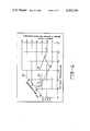
- FIG. 1is a partially schematic diagram of air conditioning apparatus according to the invention, and including a solar collector, an energy storage tank, and a chemical dehumidifier;
- FIG. 2is a psychometric chart illustrating one way of operating the apparatus of FIG. 1;
- FIG. 3is a partially schematic diagram of air conditioning apparatus according to the invention, and including a solar collector, an energy storage tank, a chemical dehumidifier and absorption refrigeration apparatus;
- FIG. 4is a psychometric chart illustrating one way of operating the apparatus of FIG. 3;
- FIG. 5is a partially schematic diagram of air conditioning apparatus according to the invention, and including a solar collector, an energy storage tank, a chemical dehumidifier and refrigeration apparatus of the compressor-condenser-evaporator type driven by a rankine cycle engine;
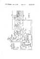
- FIG. 6is a schematic diagram of air conditioning apparatus according to the present invention in which a desiccant from a chemical dehumidifier is regenerated with both solar energy and waste energy from a diesel engine which drives an air conditioner compressor; and
- FIG. 7is a schematic diagram of air conditioning apparatus according to the present invention in which a liquid desiccant in a first dehumidification stage is regenerated with solar energy and a dry desiccant in a second dehumidification stage is regenerated with waste heat from a diesel engine which drives an air conditioner compressor.
- air conditioning apparatuscomprising a solar collector 10, a heated water storage tank 11, and dehumidification apparatus including a contactor 12 and a regenerator 13.
- a heat transfer fluidusually treated water, is circulated from the tank 11 through a line 14 to a pump 15, and from thence through a line 16 to the solar collector 10. Heated fluid returns from the collector 10 through a line 17 to the tank 11.
- the pump 15is controlled to maintain a predetermined fluid temperature, say, 140° F., within the tank 11.
- fresh airis dehumidified by drawing the air through a spray of an aqueous hygroscopic solution of a glycol in the contactor 12.
- the hygroscopic solutionis recirculated through the contactor 12 from a collection reservoir located at the bottom of the contactor 12. A portion of the solution in the reservoir is also circulated through the regenerator 13 where it is concentrated by evaporating water from the solution. Concentrated solution is returned from the regenerator 13 to the contactor 12.
- the aqueous hygroscopic solutionis circulated by a pump 18 through a line 19, an indirect heat exchanger 20 and a line 21 to the regenerator 13.
- the concentrated solutionis then returned by a pump 22 through a line 23, the indirect heat exchanger 20, and a line 24 back into a reservoir in the contactor 12.
- the glycol solutionis also circulated by a pump 25 from the regenerator 13 through a line 26 to a heat exchange coil 27 positioned within the tank 11 where the solution is heated, and thence through a line 28 to spray nozzles 29 within the regenerator 13.
- Preheated airenters the regenerator 13 at the upper left, travels downwardly with the heated glycol solution sprayed from the nozzles 29, past a baffle 31, and then upwardly through the blower 30 to be discharged from the system along with water evaporated from the heated glycol solution.
- the regenerator 13can be controlled conveniently by utilizing a by-pass 32, under the control of a valve 33 to maintain the temperature of the glycol solution leaving the nozzles 29 at a predetermined control level.
- Hygroscopic glycol solutionsare available, for example, for which a predetermined controlled temperature on the order of 120° F. to 130° F. is sufficient to evaporate the water from the solution.
- the hygroscopic glycol solutionis also circulated from the reservoir in the contactor 12 by a pump 34 through a three-way valve 35 and a line 36 to a coil 37 of an evaporative cooler or cooling tower 38.
- the cooling tower 38transfers to a heat sink, the atmosphere, heat of sorption from the dehumidification process.
- Heat of sorptionmay be defined as a change from latent heat to sensible heat including the latent heat of condensation of water vapor and any heat of solution resulting from the mixing of the water removed from the dehumidified air with the glycol solution, or other hygroscopic material.
- the cooled glycol solution from the coil 37flows through a line 39 and is sprayed from nozzles 40 within the contactor 12.
- Fresh airis drawn into the contactor 12 by a blower 41, is dehumidified and, usually, cooled sensibly, by contact with the glycol solution sprayed from the nozzles 40.
- the contactor 12can be controlled by using a by-pass 42, under the control of a valve 43 to maintain a predetermined dry bulb temperature at the inlet to the blower 41.
- the contactor 12requires a cooled glycol solution while the regenerator 13 requires a heated solution.
- the warm concentrated solution pumped from the regenerator 13 to the contactor 12is therefore passed through the heat exchanger 20 where some of the unwanted heat in the concentrated solution is transferred to the cool dilute solution being pumped from the contactor 12 to the regenerator 13.
- the heat exchanger 20increases the efficiency of the dehumidification apparatus.
- Conditioned airleaves the contactor 12 in a duct 44 where it is mixed with return air in a duct 45 of a conventional air distribution system (not illustrated).
- the mixture of dehumidified fresh air and return airflows from the duct 44 through an indirect heat exchanger 46 and into a duct 47, from which it is delivered to the air distribution system.
- the duct 45may be connected to mix the return and fresh air prior to dehumidification in the contactor 12.
- the indirect heat exchanger 46the mixture of dehumidified fresh air and return air is cooled sensibly by contact with an indirect heat exchange coil 48 through which chilled water from a conventional source (not illustrated) is circulated as required to maintain a desired dry bulb temperature in the duct 47.
- the air entering the left side of the regenerator 13is pre-heated. This can be accomplished by delivering the regenerating air, preferably relief air from the building being conditioned, through a line 49 to an indirect air-to-air heat exchanger 50. Hot, saturated air within the regenerator 13 flows through the opposite side of the indirect heat exchanger 50 before entering the blower 30 for discharge from the regenerator 13.
- building exhaust air in the line 49may have a dry bulb temperature of about 83° F. and a dew point of about 56° F., while air entering the heat exchanger 50 from the regenerator 13 may be saturated at 120° F.
- the psychometric chartillustrates a preferred mode of operating the apparatus of FIG. 1.
- Outside air entering the contactor 12 having a dry bulb temperature of 92° F. and a wet bulb temperature of 76° F., point Ais dehumidified and cooled, and then enters the duct 44 at a dry bulb temperature of 85° F. and a wet bulb temperature of 48° F., point B, and is mixed with 61/2 times its weight of return air having a dry bulb temperature of 81° F. and a wet bulb temperature of 56° F., point C.
- the mixturehas a dry bulb temperature of 82° F. and a wet bulb temperature of 55° F., point D.
- the mixturecan be cooled sensibly in the indirect heat exchanger 46 to a dry bulb temperature of 63° F. without changing its wet bulb temperature, point E, and will be heated to a dry bulb temperature of about 67° F., point F, in the building distribution system (not illustrated), so that it can be used as required to maintain a control condition: dry bulb temperature 76° F. and wet bulb temperature 56° F., point G. It has been found that the apparatus of FIG. 1, when operated as just described, requires about 3.2 tons of refrigeration for the indirect heat exchanger 46 and 1 ton of refrigeration for the chemical dehumidifier to condition a given number of pounds of air per hour as described.
- airis conditioned at the same given rate, but by mixing outside air and return air, and cooling and dehumidifying this mixture by means of a chilled, indirect heat exchange coil, it is found that: (1) the mixture has to be chilled to a dry bulb temperature of about 58° F. to achieve the required dehumidification; (2) the mixture, after dehumidification must be reheated to about 67° F.; and (3) the energy requirement, for cooling, dehumidifying and reheating, is equivalent to about 4.8 tons of refrigeration.
- the solar collector 10will collect insufficient heat for regenerating the hygroscopic glycol solution. For example, on certain hot, humid days, heavy cloud cover may limit the solar energy intercepted by the collector 10. Additional energy will also be required if the apparatus is operated at night.
- a steam or other heat source 51may be connected to a coil 52 located to heat water in the storage tank 11 during such conditions. In many cities, large office buildings are heated during cold weather with steam purchased from a utility company such as an electric company. The steam, which may be a by-product from the utility company, is also available in the summer and may be used when necessary for heating water in the tank 11 to provide sufficient energy for operating the regenerator 13.
- the apparatusgenerally comprises a collector 60 for solar energy, a storage tank 61 for heated heat transfer fluid, dehumidification apparatus including a contactor 62 and a regenerator 63, and absorption refrigeration apparatus shown schematically as including a generator 64, a condenser 65, an evaporator 66 and an absorber and heat exchanger 67.
- a heat transfer fluidusually treated water, is circulated from the tank 61 through a line 68 by a pump 69, and thence through a line 70 to the solar collector 60. Heated fluid returns from the collector 60 through a line 71 to the tank 61.
- the pump 69is controlled to maintain a predetermined fluid temperature, for example, 200° F., within the tank 61.
- a predetermined fluid temperaturefor example, 200° F.
- the fluidmay be heated from an auxiliary steam source 72 connected to a heat exchanger coil 73 in the tank 61 or by any other convenient means.
- An aqueous hygroscopic solution of a glycolis circulated by a pump 74 from a reservoir in the contactor 62 through a line 75, an indirect heat exchanger 76 and a line 77 to the regenerator 63 for concentration, while the concentrated solution is circulated by a pump 78 through a line 79, the indirect heat exchanger 76, and a line 80 back to the contactor 62.
- the glycol solutionis also circulated by a pump 81 from the regenerator 63 through a line 82 and a heat exchange coil 83 positioned within the condenser 65 wherein the fluid is heated, and thence through a line 84 and spray nozzles 85 within the regenerator 63.
- Three-way valves 86 and 87may also be provided in the lines 82 and 84, respectively, for selectively circulating at least a portion of the fluid through a heat exchange coil 88 in the solar energy storage tank 61 in place of the condenser 65. This enables heating the glycol solution for regeneration directly from the solar energy storage tank when the absorption refrigeration apparatus is not in use.
- the heated glycol solutionis regenerated by air drawn into the regenerator 63 by a blower 89 and through an indirect heat exchanger 90.
- the airpreferably building exhaust air, travels downwardly on the left side of the regenerator 63 with glycol solution sprayed from the nozzles 85, laterally to the right, and then upwardly through the indirect heat exchanger 90 and the blower 89 to be discharged from the system along with water vaporized from the heated glycol solution.
- the regenerator 63can be controlled conveniently by utilizing a by-pass 91, under the control of a valve 92, to maintain the temperature of the glycol solution leaving the nozzles 85 at a predetermined control temperature.
- the indirect heat exchanger 76heats the dilute glycol solution flowing from the contactor 62 to the regenerator 63 while simultaneously cooling the concentrated glycol solution flowing from the regenerator 63 to the contactor 62, thereby increasing the efficiency of the dehumidification apparatus.
- the glycol solutioncan be circulated from the contactor 62 by a pump 93 through a three-way valve 94 and a line 95 to a heat exchange coil 96 in an evaporative cooler or cooling tower 97. Cooled glycol solution from the coil 96 can flow through a line 98 and a valve 99, and be sprayed from nozzles 100 within the contactor 62. Either fresh air or a mixture of fresh and return air is drawn into the contactor 62 by a blower 101, and is dehumidified and, usually, cooled sensibly, by contact with the glycol solution being sprayed from the nozzles 100.
- the contactor 62can be controlled by using a by-pass 102 under the control of a valve 103, to maintain a predetermined dry bulb temperature at the inlet to the blower 101.
- Operation of the apparatus of FIG. 3 as described, i.e., using the evaporative cooler 97 to remove heat from the glycol solution, as required, to maintain the predetermined dry bulb temperature at the inlet to the blower 101is preferred when the outside wet bulb temperature is comparatively low.
- the valves 94 and 99can be set to circulate at least a portion of the glycol solution through a heat exchange coil 104 in the evaporator 66 of the absorption refrigeration apparatus. As is subsequently explained in more detail, this constitutes a particularly advantageous way to operate the apparatus of FIG. 3.
- the absorption refrigeration apparatusis of a conventional design.
- a heat exchange coil 105 in the storage tank 61is connected to supply heated heat transfer fluid to a heat exchange coil 106 in the generator 64.
- Heat supplied to the generator 64evaporates a refrigerant which is carried by a line 107 to the condenser 65.
- Heatis liberated.
- Heatmay be absorbed by hygroscopic fluid circulated through the coil 83 to heat such fluid as required for evaporating water vapor from the fluid in the regenerator 63. Any remaining unwanted heat in the condenser 65 may be absorbed by a heat transfer fluid circulated through a heat exchange coil 108 in the cendenser 65.
- the heated heat transfer fluidflows through a line 109 to a heat exchange coil 110 in the evaporative cooler or cooling tower 97 and the cooled fluid is returned through a pump 111 and a line 112 to the coil 108.
- the liquefied refrigerant in the condenser 65passes through a line 113 which includes an expansion valve 114 to the evaporator 66.
- refrigerantis vaporized in the evaporator 66, heat is absorbed from heat transfer fluid circulated through the coil 104 and through a heat exchange coil 115.
- the vaporized refrigerantflows through the absorber and heat exchanger 67, wherein it is again liquefied and returned to the generator 64.
- the pump 111also circulates heat transfer fluid through the line 112, a heat exchange coil 116 in the absorber and heat exchanger 67, the line 109 and the heat exchange coil 110 in the evaporative cooler 97 for removing waste heat from the absorber and heat exchanger 67.
- heat transfer fluidmay be circulated through the solar collector 60 at a rate to maintain a temperature of about 200° F. in the solar energy storage tank 61. If refrigerant is heated to substantially 200° F. in the generator 64 by heat transfer from the solar energy storage tank 61, the absorption refrigeration apparatus will cool the evaporator coil 104 to about 55° F. for cooling the glycol solution which dehumidifies air passed through the contactor 62. At the same time, the dilute glycol solution in the regenerator 63 is heated to about 140° F. by circulating a portion of the solution through either the condenser coil 83 or the coil 88 in the solar energy storage tank 61. At these operating temperatures, air leaving the contactor 62 can be cooled to a dry bulb temperature of about 55° F. and dehumidified to a wet bulb temperature of about 30° F.
- the conditioned air delivered to an air conditioned spacecan also be cooled.
- the blower 101draws air through the contactor 62 wherein moisture is removed from the air through contact with the hygroscopic glycol solution.
- the dehumidified airthen flows through a duct 117 to a space, room or building being conditioned.
- the duct 117passes through an indirect heat exchanger 118 wherein the dehumidified air may be sensibly cooled to a predetermined temperature.
- the indirect heat exchanger 118includes a heat exchange coil 119 which is connected through lines 120 and 121 to a heat exchange coil 122 in the evaporative cooler 97.
- a pump 123may be operated to circulate a heat transfer fluid between the coil 119 where heat is absorbed from the dehumidified air and the coil 122 where the absorbed heat energy is dissipated in air and water passed through the cooler 97.
- the heat exchanger 118also includes a heat exchange coil 124 through which a chilled heat transfer fluid may be circulated.
- the coil 124is connected through lines 125 and 126 to the heat exchange coil 115 in the evaporator 66 of the absorption refrigeration apparatus. Heat transfer fluid which is chilled in the evaporator 66 may be circulated through the coil 124 for cooling air flowing through the duct 117.
- the duct 117may be connected to receive return air from a duct 127.
- the duct 127passes through a heat exchanger 128 wherein the return air may be cooled, when necessary, prior to mixing with the dehumidified fresh air in the duct 117.
- the heat exchanger 128includes a heat exchange coil 129 which is connected through a three-way valve 130 to the line 125 and is connected directly to the line 126 for receiving chilled heat transfer fluid from the coil 115 in the evaporator 66 of the absorption refrigeration apparatus.
- the return air duct 127may be connected to mix the return air with the fresh air entering the contactor 62 instead of connecting it to mix the return air with the dehumidified air in the duct 117 (as shown).
- the heat exchanger 128may be by-passed or the valve 130 may be closed to prevent circulation of a cooled heat exchange fluid through the coil 129 in the heat exchanger 128.
- the dehumidified mixture of return air and fresh airmay be cooled sensibly in the heat exchanger 118, if necessary.
- the duct 117 carrying dehumidified air from the contactor 62also may be connected to pass through a humidifier or washer 131.
- a pump 132circulates water to a plurality of nozzles 133 which spray a mist of water for humidifying the air delivered to the air conditioned space, and simultaneously adiabatically cooling such air.
- FIG. 4a psychometric chart is shown for a mode of operation in which the air delivered to an air conditioned space is adiabatically cooled by means of the washer 131.
- FIG. 4shows the conditioning of outside or fresh air having a dry bulb temperature of 102° F. and a wet bulb temperature of 44° F., point A. This air is mixed with half its weight of return air having a dry bulb temperature of 81° F.
- the mixtureresults in air having a dry bulb temperature of about 95° F. and a wet bulb temperature of about 48° F., point C.
- This mixtureis delivered to the contactor 62 wherein it is dehumidified and cooled to a dry bulb temperature of 84° F. and a wet bulb temperature of 35° F., point D.
- the airis then adiabatically cooled in the washer 131 to a dry bulb temperature of 63° F. and a wet bulb temperature of 55° F., as shown at point E.
- the airenters the building distribution system in a condition identical to that discussed in reference to FIG. 2.
- the airwill be heated within the distribution system to a dry bulb temperature of 67° F. without changing the wet bulb temperature of 55° F., point F, and under these conditions is delivered to the air conditioned space as required to maintain a dry bulb temperature of 76° F. within the space.
- the apparatus shown in FIG. 3, operated as describedcools the mixture of outside air and return air to a dry bulb temperature of about 63° F. This is done by dehumidifying to a lower dew point than is required for humidity control, followed by adiabatic washing, and can be accomplished at fairly high contactor temperatures, e.g., temperatures which can be achieved in the coil 96 (FIG.
- the evaporative cooler 97provides that dry ambient air is available as indicated by point A in FIG. 4.
- the hygroscopic glycol solutionmust be circulated through the coil 104 of the evaporator 66 to accomplish this result.
- the evaporator 66need not provide a particularly low temperature, 70° F. being entirely adequate, and a temperature that can be readily achieved when the condenser 65 is at 140° F., or at a temperature sufficiently high to enable regeneration of the glycol solution.
- air conditioning apparatusin another embodiment, comprises a solar collector 135, chemical dehumidification apparatus including a contactor 136 and a regenerator 137 and refrigeration apparatus including a compressor 138, a condenser 139 and an evaporator 140.
- the compressor 138 of the refrigeration apparatusis driven by an expander 141, which is a part of a rankine cycle engine.
- a refrigerantsuch as F-113, is heated, as subsequently described in more detail, by energy from the solar collector 135 and flows through a line 142 to the expander 141 where its expansion drives a turbine (not illustrated) which is operatively connected through a shaft 143 in driving relationship with the compressor 138.
- Refrigerantflows from the expander 141 through a line 144, a regenerator 145, a line 146, the condenser 139 and a line 147 to a pump 148.
- Refrigerantflows from the pump 148 through a line 149 back to the opposite side of the regenerator 145 and from thence through a line 150 to a storage tank 151 for water heated in the solar collector 135 or using augmenting heat, as subsequently explained.
- Refrigerant flowcan be controlled so that the temperature entering the expander 141 is about 200° F., while the temperature entering the condenser 139 is about 140° F.
- Refrigerantis circulated from the condenser 138 through a line 152 to the condenser 139, and, thence, through a line 153 to the evaporator 140, where it can be flashed to a temperature of about 70° F. before being returned to the compressor 138.
- a hygroscopic solution of a glycolis circulated by a pump 154 through a line 155 from the contactor 136, and is delivered to a three-way valve 156 which divides the flow between a line 157 and a line 158.
- the glycol solution flowing in the line 157is delivered to the evaporator 140 and from there flows through lines 159 and 160 into the contactor 136 to be sprayed from nozzles 161.
- Glycol solution delivered to the line 158flows directly to the line 160 and to the nozzles 161.
- the three-way valve 156is controlled to maintain a predetermined temperature of the hygroscopic glycol solution sprayed from the nozzles 161.
- Heatis transferred from the condenser 139 to a hygroscopic glycol solution which is circulated from the regenerator 137 by a pump 162 through a line 163, and to a three-way valve 164 which divides the flow between a line 165 and a line 166.
- the hygroscopic glycol solution delivered to the line 165is circulated to the condenser 139 where it is heated by heat transferred thereto from refrigerant from the compressor 138 and from refrigerant circulated in the solar energy collection system, and is then returned through a line 167 into the regenerator 137, where it is sprayed from nozzles 168.
- the three-way valve 164is controlled to divide the flow of hygroscopic glycol solution through the condenser 139, as just described, and through the line 166 to maintain a predetermined temperature of the solution as it is sprayed within the regenerator 137.
- Airpreferably relief air from the building served by the apparatus, enters the regenerator 137, as indicated by an arrow 169, passes through an indirect air-to-air heat exchanger 170, and from thence through an indirect air-to-liquid heat exchanger 171 and then downwardly with hygroscopic glycol solution being sprayed from the nozzles 168, laterally to the left and then upwardly through the opposite side of the air-to-air heat exchanger 170 and a blower 172 by which it is discharged from the regenerator 137, through an indirect heat exchanger 173 and then is exhausted through a duct 174.
- Heatis transferred to the air entering the regenerator 137 (a) from air traveling upwardly through the regenerator 137 to the blower 172 in the indirect heat exchanger 170 and (b) from hygroscopic glycol solution circulated as subsequently described in more detail through the indirect heat exchanger 171. Heat is also transferred from the effluent from the blower 172 in the indirect heat exchanger 173 as subsequently described in more detail.
- the apparatuscan be operated so that air from inside the regenerator 137 entering the indirect heat exchanger 170 is saturated with water vapor and at a dry bulb temperature of 120° F. By indirect heat exchange with the building exhaust air, which can enter the indirect heat exchanger 170 at a dry bulb temperature of about 83° F.
- the exhaust air entering the blower 171can be at a dry bulb temperature of 96° F., and have a dew point of 79° F. while, as a consequence of heat transfer in the indirect heat exchanger 173, the exhausted air in the duct 174 can be saturated with water vapor and at a dry bulb temperature of about 75° F.
- Airis drawn into the contactor 136 by a blower 175, and flows downwardly therethrough in contact with cooled hygroscopic glycol solution from the nozzles 161, then laterally to the left and upwardly through the blower 175, a line 176, an adiabatic washer indicated generally at 177 and a duct 178 to a space (not illustrated) to be air conditioned.
- the apparatus of FIG. 5also includes an evaporative cooler 188 from which cool water can be circulated by a pump 189 through a line 190 to an auxiliary coil (not illustrated) in the condenser 139. Water is returned from the condenser 139 through a line 191. Water from the cooler 188 is used to maintain a thermal balance whenever there is excess heat in the condenser 139 above that required by the regenerator 137.
- the apparatus of FIG. 5is designed to condition air when the outside dew point is comparatively high, e.g., a dry bulb temperature of 92° F. and a wet bulb temperature of 76° F.: point A, FIG. 2, and to condition that air or, preferably, a mixture of that air with return room air to a lower wet bulb temperature than is required for humidity control in the space, e.g., a dry bulb temperature of 84° F. and a wet bulb temperature of 35° F.: point B, FIG. 4.
- This aircan then be adiabatically washed in the washer 177, distributed throughout the building, and used as required to maintain temperature and humidity.
- a refrigerant that has been heated by energy from the solar collector 135flows through a line 142 to the expander 141.
- Refrigerant in the line 142has been heated as it flowed through a liquid-to-liquid indirect heat exchanger 192 in the heated water storage tank 151.
- a liquid-to-liquid indirect heat exchanger 192in the heated water storage tank 151.
- the apparatusalso includes an indirect liquid-to-liquid heat exchanger 196 within the storage tank 151. Whenever required heat from the solar collector 135 can be supplemented, or replaced, by heat from an auxiliary steam source 197 connected to the indirect heat exchanger 196.
- a heating, ventilating and air conditioning systemis shown in which thermal energy from a solar collector 200 is augmented with waste heat from a diesel engine 201 for regenerating a desiccant such as a glycol solution in a regenerator 202.
- Outside airpasses from an air intake 203 through a chemical dehumidifier 204 which may, for example, be the same as the contactor 12 shown in FIG. 1.
- a chemical dehumidifier 204Within the dehumidifier 204, moisture is removed from the fresh outside air.
- heat of sorptionis transferred through a coil 205 to a cooling tower 206 and thence transferred to the atmosphere.
- the dehumidified airpasses through a duct 207 along with return air from a duct 208 to a cooling coil 209.
- Heat transfer fluidis circulated from the cooling coil 209 to refrigeration apparatus 210.
- the refrigeration apparatus 210transfers heat from the cooling coil 209 to a cooling tower 211 in a conventional manner.
- the refrigeration apparatus 210is driven by the diesel engine 201.
- the diesel engine 201may also be connected to drive an electric generator 212 and an emergency power generator 213, when desired.
- the dehumidified and chilled air discharged from the cooling coil 209passes through a blower 214 and a duct 215 and is then discharged through defusers 216 located in the ceiling of an air conditioned space 217.
- Building exhaust air and return air from the space 217is drawn through a lighting fixture 218 into a duct 219 by return air fan 220.
- return airpasses through the lighting fixture 218, waste thermal energy is removed from such lighting fixture 219.
- As much as 50 percent or more of the lighting fixture thermal loadmay be removed from the space 217 by exhausting the return air through the lighting fixture 218. This in turn decreases the quantity of air needed to be supplied to the space 217 to maintain a desired space temperature.
- the return air withdrawn from the space 217 through the lighting fixtures 218will be at an appreciably higher temperature than the normal temperature of the conditioned space 217. For example, if the space 217 is maintained at 75° F., the return air may be on the order of 87° F.
- a portion of the return airis exhausted from the building through the regenerator 202.
- the duct 208is connected to a duct 221 in which a portion of the return air is mixed with outside air, as needed, from a duct 222.
- a blower 223forces air from the duct 221 through the regenerator 202 and exhausts the moisture laden air through a building exhaust duct 224.
- a pump 225is connected to circulate a dilute glycol solution from the contactor 204 to the regenerator 202 and to return concentrated glycol solution from the regenerator 202 to the contactor 204.
- the glycol solution within the regenerator 202is heated by a coil 226 through which a hot heat transfer solution is circulated.
- the heat transfer solutionis circulated to receive solar energy from the solar collector 200 and also to receive thermal energy from a coil 227 located in the exhaust stach for the diesel engine 201. Through the use of solar energy from the solar collector 200 and exhaust energy from the coil 227 in the diesel engine exhaust stack, sufficient heat is available for maintaining the desiccant within the regenerator 202 at 200° F.
- FIG. 7still a further modified embodiment is shown of apparatus for conditioning air within a space 250.
- the apparatusgenerally uses two stages of dehumidification, refrigeration apparatus driven from a diesel engine and an evaporative cooler for cooling air supplied through a ceiling diffuser 251 to the space 250.
- a combination of solar energy and waste heat from the diesel engine which drives the refrigeration apparatusis used for regenerating desiccant for the two stages of dehumidification.
- a blower 252is connected to withdraw air from the space 250 through lighting fixtures 253 located within a ceiling 254 for the conditioned space 250. As air is withdrawn through the lighting fixtures 253, a portion of the heat produced by the lighting fixtures 253 is withdrawn from the space 250, thereby reducing the quantity of air needed to be supplied through the diffuser 251 to cool the space 250 to a desired temperature. A portion of the air withdrawn from the space 250 by the blower 252 is circulated through a duct 255 to a mixing valve or chamber 256. Fresh air which is to be added to the conditioned space 250 enters the apparatus through a duct 257.
- Fresh air entering through the duct 257passes through a contactor or chemical dehumidifier 258 wherein it contacts a spray of a liquid chemical desiccant, such as a glycol solution.
- a contactor or chemical dehumidifier 258wherein it contacts a spray of a liquid chemical desiccant, such as a glycol solution.
- heat of sorptionis generated.
- a heat transfer fluid circulated between a coil or indirect heat exchanger 259 and a cooling tower 260removes the heat of sorption from the dehumidified fresh air.
- the dehumidified fresh airleaves the dehumidifier 258 through a duct 261 which connects with the mixing valve or chamber 256 wherein it mixes with recirculated air from the space 250.
- the dehumidifier 262is in the form of a rotating wheel having a crystalline desiccant, such as silica gel, located within a porous honeycomb structure. As the dehumidifier 262 is rotated about an axis 263, the air mixture passing through the dehumidifier 262 is exposed to regenerated desiccant crystals for removing moisture from such air mixture. From the dehumidifier 262, the air passes into a duct 264 which is connected through a first indirect heat exchanger coil 265 and a second indirect exchange coil 266 to a fan or blower 267.
- a duct 264which is connected through a first indirect heat exchanger coil 265 and a second indirect exchange coil 266 to a fan or blower 267.
- the first indirect heat exchange coil 265is connected to a cooling tower 268 for removing heat of sorption from the dehumidified air mixture leaving the dehumidifier 262 and dissipating such heat of sorption to the atmosphere.
- the second indirect heat exchange coil 266is cooled by refrigeration apparatus 269.
- a diesel engine 270drives the refrigeration apparatus 269 for transferring heat from the second coil 266 to a cooling tower 271.
- the blower 267circulates the cooled air from the second coil 266 through an evaporative cooler 272 to the diffuser 251 located within the ceiling structure 254 over the conditioned space 250. Within the evaporative cooler 272, moisture is evaporated into the air to decrease the temperature of such air.
- Air supplied from the evaporative cooler 272 to the space 250may, for example, have a temperature on the order of 40° F. This low temperature is achieved through the use of a minimum load on the refrigeration apparatus 269.
- a pump 273circulates dilute desiccant from the dehumidifier 258 to a regenerator 274 and returns a concentrated desiccant from the regenerator 274 back to the dehumidifier 258.
- a pump 275circulates a heat transfer fluid between a coil 276 within the regenerator 274 and a solar energy collector 277. The heat transfer fluid is heated to a predetermined high temperature, such as approximately 200° F., within the solar collector 277. The heated heat transfer fluid is then circulated from the solar collector 277 to the coil 276 where such heat is transferred to the dilute hygroscopic solution during regeneration.
- the dilute solutionAfter the dilute solution is heated, it is contacted with air which picks up moisture from the dilute solution and then the hot moist air is discharged through a duct 278 to the atmosphere.
- air supplied to the regenerator 274is in the form of exhaust air from the conditioned space 250.
- the return air duct 255is connected through a blower 279 to supply building exhaust air to the regenerator 274.
- Fresh outside air, as needed,is also supplied from a duct 280 through the blower 279 through the regenerator 274.
- the diesel engine 270is connected to drive the refrigeration apparatus 269 and also to drive auxiliary electric generator 281.
- the output from the electric generator 281may be used, for example, for driving the various pumps, blowers and fans within the system for conditioning air within the building space 250. In addition, it may be used for any other desired purpose. If the environmental control system shown in FIG.
- the diesel enginemay also be connected through a clutch 282 for driving an emergency electric generator 283 during a failure of the commercial power source used for operating lighting and equipment in such hospital.
- Waste heatis a by-product from operation of the diesel engine 270.
- a pump 284circulates a heat transfer fluid, such as water, through passages around cylinders within the internal combustion engine 270 for cooling such cylinders.
- the pump 284circulates such water from the engine 270 to an indirect fluid-to-air heat exchange coil 285.
- Exhaust gasesalso carry waste heat from the engine 270.
- the exhaust gasespass through an indirect air-to-air heat exchanger 286 for recovering waste heat from such exhaust gases.
- the granular desiccant within the dehumidifier 262is regenerated with exhaust air from the building space 250 along with the regeneration of liquid desiccant within the regenerator 274.
- a portion of the air withdrawn from the space 250 by the blower 252flows from the blower 252 into a duct 287.
- the duct 287is connected sequentially through the heat exchanger 285 and the heat exchanger 286.
- the hot water circulated through the heat exchanger 285may, for example, heat the air in the duct 287 to approximately 200° F.
- the hot exhaust gases passing through the heat exchanger 286further heats this air to approximately 300° F. The 300° F.
- air leaving the heat exchanger 286 in the duct 287is circulated through the dehumidifier 262 to regenerate the desiccant therein.
- the hot air within the duct 287is circulated through a portion of the desiccant within the dehumidifier 262 as the wheel containing the desiccant rotates.
- the portion of the hot air circulated through the desiccant for regenerationis spaced from the portion of the regenerated desiccant contacted by air circulated through the duct 264 for delivery to the conditioned space 250.
- a blower or fan 288withdraws the moisture-laden hot air from the dehumidifier 262 and discharges such air through a duct 289 to the atmosphere outside the building containing the conditioned space 250.
- FIGS. 6 and 7represent considerable increase in energy efficiency over a conventional system in which chilled fresh air is mixed with recirculated air for conditioning spaces within a building.
- the efficienciesare also increased over prior art solar systems because there is not a total reliance on the availability of solar energy.
- both the waste heat from the diesel engine and solar energyare available for winter heating.
- a diesel enginewas operated to drive refrigeration apparatus and to drive generators which serve as a source of electricity for powering the system.
- the diesel enginealso produces waste heat which is used for regeneration of a desiccant within a chemical dehumidifier.
- the diesel enginecan be replaced with a bank of fuel-cells.
- a fuel-celldirectly converts a fuel and an oxidant into an electric current and, as a by-product, also produces heat.
- the heat leveldepends upon the construction of the fuel-cell and various other factors such as the nature of the fuel and the oxidant used within the fuel-cell.
- Various fuel-cellsoperate anywhere from relatively low temperatures, below 200° C., up to very high temperatures, above 900° C.
- a bank of fuel-cellsmay be used to replace the diesel engine and the electric generators within the systems of either FIG. 6 or FIG. 7.
- the fuel-cellgenerates electricity which operates the various fans, blowers and pumps within the system and, when necessary, also drives electrically powered refrigeration apparatus. Waste heat from the fuel-cell is transferred to air circulated through a desiccant regenerator or through a granular or solid desiccant for removing moisture from such desiccant. The hot, moisture-laden air is then discharged to the atmosphere.
- the dehumidifiercan be reversed for humidifying fresh air supplied to a space.
- a heated dilute hygroscopic glycol solution, or even water,can be sprayed in the contactor 12 (FIG. 1) for humidifying air circulated through the contactor.
- the solar energy collectoris used for heating such solution.
- the temperature of the solution and the rate at which it is sprayed from the contactor nozzlesis controlled to give a desired wet bulb temperature at the outlet from the contactor.
- the humidified aircan then be heated, as necessary, to maintain a desired temperature in the space being air conditioned.
- at least one air-to-liquid heat exchanger analogous to the exchanger 171, to the exchanger 173, or to both (FIG. 5)can be used in a similar manner in the apparatus of FIG. 1 or in the apparatus of FIG. 3.
Landscapes
- Engineering & Computer Science (AREA)
- Chemical & Material Sciences (AREA)
- General Engineering & Computer Science (AREA)
- Mechanical Engineering (AREA)
- Combustion & Propulsion (AREA)
- Life Sciences & Earth Sciences (AREA)
- Sustainable Energy (AREA)
- Sustainable Development (AREA)
- Thermal Sciences (AREA)
- Physics & Mathematics (AREA)
- Analytical Chemistry (AREA)
- General Chemical & Material Sciences (AREA)
- Oil, Petroleum & Natural Gas (AREA)
- Chemical Kinetics & Catalysis (AREA)
- Central Air Conditioning (AREA)
- Drying Of Gases (AREA)
Abstract
Description
Claims (17)
Priority Applications (1)
| Application Number | Priority Date | Filing Date | Title |
|---|---|---|---|
| US05/958,485US4222244A (en) | 1978-11-07 | 1978-11-07 | Air conditioning apparatus utilizing solar energy and method |
Applications Claiming Priority (1)
| Application Number | Priority Date | Filing Date | Title |
|---|---|---|---|
| US05/958,485US4222244A (en) | 1978-11-07 | 1978-11-07 | Air conditioning apparatus utilizing solar energy and method |
Related Parent Applications (1)
| Application Number | Title | Priority Date | Filing Date |
|---|---|---|---|
| US05777049Continuation | 1977-03-14 |
Publications (1)
| Publication Number | Publication Date |
|---|---|
| US4222244Atrue US4222244A (en) | 1980-09-16 |
Family
ID=25500985
Family Applications (1)
| Application Number | Title | Priority Date | Filing Date |
|---|---|---|---|
| US05/958,485Expired - LifetimeUS4222244A (en) | 1978-11-07 | 1978-11-07 | Air conditioning apparatus utilizing solar energy and method |
Country Status (1)
| Country | Link |
|---|---|
| US (1) | US4222244A (en) |
Cited By (85)
| Publication number | Priority date | Publication date | Assignee | Title |
|---|---|---|---|---|
| US4429545A (en) | 1981-08-03 | 1984-02-07 | Ocean & Atmospheric Science, Inc. | Solar heating system |
| US4535754A (en)* | 1981-02-23 | 1985-08-20 | D&M Investments | Manufactured fuel assisted solar heat exchanger |
| WO1987005683A1 (en)* | 1986-03-19 | 1987-09-24 | Purdue, John, C. | Air conditioning apparatus |
| US4703629A (en)* | 1986-12-15 | 1987-11-03 | Moore Roy A | Solar cooling apparatus |
| WO1988008947A1 (en)* | 1987-05-12 | 1988-11-17 | Purde, John, C. | Air conditioning apparatus |
| US4860548A (en)* | 1988-06-13 | 1989-08-29 | Ahlstromforetagen Svenska Ab | Air conditioning process and apparatus therefor |
| US4864830A (en)* | 1988-06-13 | 1989-09-12 | Ahlstromforetagen Svenska Ab | Air conditioning process and apparatus |
| US4955205A (en)* | 1989-01-27 | 1990-09-11 | Gas Research Institute | Method of conditioning building air |
| US4963231A (en)* | 1988-06-13 | 1990-10-16 | Ahlstromforetagen Svenska Ab | Method for evaporation of liquids |
| US5058394A (en)* | 1990-02-06 | 1991-10-22 | Battelle Memorial Institute | Hybrid air conditioning system subsystem integration |
| US5070703A (en)* | 1990-02-06 | 1991-12-10 | Battelle Memorial Institute | Hybrid air conditioning system integration |
| US5097668A (en)* | 1990-10-30 | 1992-03-24 | Walter F. Albers | Energy reuse regenerator for liquid desiccant air conditioners |
| US5300138A (en)* | 1993-01-21 | 1994-04-05 | Semco Incorporated | Langmuir moderate type 1 desiccant mixture for air treatment |
| US5401706A (en)* | 1993-01-06 | 1995-03-28 | Semco Incorporated | Desiccant-coated substrate and method of manufacture |
| US5685152A (en)* | 1995-04-19 | 1997-11-11 | Sterling; Jeffrey S. | Apparatus and method for converting thermal energy to mechanical energy |
| WO2001079771A1 (en)* | 2000-04-14 | 2001-10-25 | Work Smart Energy Enterprises, Inc. | Solar air conditioner |
| US6536677B2 (en)* | 2000-06-08 | 2003-03-25 | University Of Puerto Rico | Automation and control of solar air conditioning systems |
| US6539738B2 (en) | 2000-06-08 | 2003-04-01 | University Of Puerto Rico | Compact solar-powered air conditioning systems |
| WO2003012348A3 (en)* | 2001-08-01 | 2003-05-30 | Ronald S Ace | Geothermal space conditioning |
| US6688129B2 (en)* | 2001-08-01 | 2004-02-10 | Ronald S Ace | Geothermal space conditioning |
| US20040118125A1 (en)* | 2002-12-19 | 2004-06-24 | Potnis Shailesh Vijay | Turbine inlet air-cooling system and method |
| US20040221589A1 (en)* | 2003-05-09 | 2004-11-11 | Serge Dube | Energy storage with refrigeration systems and method |
| US20060037343A1 (en)* | 2004-08-17 | 2006-02-23 | Lg Electronics Inc. | Electricity generating and air conditioning system with dehumidifier |
| US20060213218A1 (en)* | 2005-03-25 | 2006-09-28 | Denso Corporation | Fluid pump having expansion device and rankine cycle using the same |
| EP1734317A1 (en)* | 2005-06-16 | 2006-12-20 | LG Electronics, Inc. | Cogeneration system |
| CN1295464C (en)* | 2002-03-03 | 2007-01-17 | 吴佶伟 | Domestic solar energy intelligent artificial environment system |
| CN100378413C (en)* | 2004-08-17 | 2008-04-02 | Lg电子株式会社 | Cogeneration system |
| CN100424446C (en)* | 2007-03-16 | 2008-10-08 | 东南大学 | Solar air pretreatment solution heat collection regeneration device |
| US20090078114A1 (en)* | 2007-09-25 | 2009-03-26 | Hess Spencer W | System and method for recovering ice-clad machinery and equipment |
| CN100554796C (en)* | 2008-05-15 | 2009-10-28 | 上海交通大学 | Solar energy driving compaction type two-stage parallel connection liquid dehumidifying air conditioner |
| US20100307171A1 (en)* | 2009-06-06 | 2010-12-09 | International Business Machines Corporation | Cooling Infrastructure Leveraging a Combination of Free and Solar Cooling |
| CN101968293A (en)* | 2010-11-03 | 2011-02-09 | 合肥美的荣事达电冰箱有限公司 | Refrigerator and control method for power supply of refrigerator |
| US7886986B2 (en) | 2006-11-08 | 2011-02-15 | Semco Inc. | Building, ventilation system, and recovery device control |
| CN102000478A (en)* | 2010-10-29 | 2011-04-06 | 中国农业大学 | Dehumidification liquid regenerating method and device |
| US20110113796A1 (en)* | 2007-08-09 | 2011-05-19 | Ayman Adnan Salim Al-Maaitah | Two-stage low temperature air cooled adsorption cooling unit |
| US20110232305A1 (en)* | 2010-03-26 | 2011-09-29 | Exxonmobil Research And Engineering Company | Systems and methods for generating power and chilling using unutilized heat |
| CN102261702A (en)* | 2011-05-28 | 2011-11-30 | 浙江理工大学 | Dual-effect solution dehumidification fresh air unit |
| US20120125031A1 (en)* | 2010-05-25 | 2012-05-24 | 7Ac Technologies, Inc. | Methods and systems for desiccant air conditioning |
| WO2012071036A1 (en)* | 2010-11-23 | 2012-05-31 | Ducool Ltd. | Air conditioning system |
| WO2012122350A1 (en) | 2011-03-08 | 2012-09-13 | Poerio Wayne | Solar turbo pump - hybrid heating-air conditioning and method of operation |
| US20120285189A1 (en)* | 2011-05-13 | 2012-11-15 | Nobuyuki Takeda | Sunlight heat utilized steam absorption chiller and sunlight heat utilization system |
| US20130125566A1 (en)* | 2011-11-18 | 2013-05-23 | Airbus Operations Gmbh | Vehicle with a cooling system for cooling and method for cooling in a vehicle |
| CN103185379A (en)* | 2013-03-29 | 2013-07-03 | 江苏大学 | Novel solar energy liquid dehumidifying air-conditioning system and implementation method |
| WO2013172789A1 (en)* | 2012-05-16 | 2013-11-21 | Nanyang Technological University | A dehumidifying system, a method of dehumidifying and a cooling system |
| EP1861659A4 (en)* | 2005-03-25 | 2014-06-25 | Ducool Ltd | System and method for managing water content in a fluid |
| US20140190195A1 (en)* | 2006-10-23 | 2014-07-10 | Ralph Muscatell | Solar energy air conditioning system with storage capability |
| US8790451B1 (en)* | 2010-09-17 | 2014-07-29 | Pvt Solar, Inc. | Method and system for integrated home cooling utilizing solar power |
| US20140245772A1 (en)* | 2013-03-04 | 2014-09-04 | Carrier Corporation | Integrated membrane dehumidification system |
| JP2015510576A (en)* | 2012-02-21 | 2015-04-09 | ウォータージー ゲーエムベーハー | System for adjusting the temperature and humidity in the housing |
| US20150176869A1 (en)* | 2013-11-27 | 2015-06-25 | King Fahd University Of Petroleum And Minerals | Intermittent absorption refrigeration system equipped with a waste energy storage unit |
| US9101874B2 (en) | 2012-06-11 | 2015-08-11 | 7Ac Technologies, Inc. | Methods and systems for turbulent, corrosion resistant heat exchangers |
| US9453666B2 (en) | 2013-01-10 | 2016-09-27 | King Saud University | Fluid system for hot and humid climates |
| US9470426B2 (en) | 2013-06-12 | 2016-10-18 | 7Ac Technologies, Inc. | In-ceiling liquid desiccant air conditioning system |
| US9506697B2 (en) | 2012-12-04 | 2016-11-29 | 7Ac Technologies, Inc. | Methods and systems for cooling buildings with large heat loads using desiccant chillers |
| US9631848B2 (en) | 2013-03-01 | 2017-04-25 | 7Ac Technologies, Inc. | Desiccant air conditioning systems with conditioner and regenerator heat transfer fluid loops |
| US20170130998A1 (en)* | 2015-11-09 | 2017-05-11 | King Fahd University Of Petroleum And Minerals | Solar-powered libr-water absorption air conditioning system using hybrid storage |
| US9709285B2 (en) | 2013-03-14 | 2017-07-18 | 7Ac Technologies, Inc. | Methods and systems for liquid desiccant air conditioning system retrofit |
| US9772127B2 (en) | 2011-03-08 | 2017-09-26 | JOI Scientific, Inc. | Solar turbo pump—hybrid heating-air conditioning and method of operation |
| EP2643640A4 (en)* | 2010-11-22 | 2018-04-25 | Munters Corporation | Desiccant dehumidification system with chiller boost |
| US10024558B2 (en) | 2014-11-21 | 2018-07-17 | 7Ac Technologies, Inc. | Methods and systems for mini-split liquid desiccant air conditioning |
| US20180259203A1 (en)* | 2015-11-24 | 2018-09-13 | Southeast University | Independent temperature and humidity processing air conditioning system driven by low-level thermal energy |
| WO2019096889A1 (en)* | 2017-11-16 | 2019-05-23 | Aquahara Technology GmbH | Method and device for obtaining water from the ambient air |
| CN109869846A (en)* | 2017-12-01 | 2019-06-11 | 陶柳成 | Zero energy consumption, zero carbon solution dehumidifies degerming except haze fresh air conditioner |
| US10323867B2 (en) | 2014-03-20 | 2019-06-18 | 7Ac Technologies, Inc. | Rooftop liquid desiccant systems and methods |
| US10619867B2 (en) | 2013-03-14 | 2020-04-14 | 7Ac Technologies, Inc. | Methods and systems for mini-split liquid desiccant air conditioning |
| US10632416B2 (en) | 2016-05-20 | 2020-04-28 | Zero Mass Water, Inc. | Systems and methods for water extraction control |
| CN111773890A (en)* | 2020-06-29 | 2020-10-16 | 南京航空航天大学 | Electrowetting-based solar regeneration solution dehumidification system and method |
| US10835861B2 (en) | 2014-11-20 | 2020-11-17 | Arizona Board Of Regents On Behalf Of Arizona State University | Systems and methods for generating liquid water from air |
| US10921001B2 (en) | 2017-11-01 | 2021-02-16 | 7Ac Technologies, Inc. | Methods and apparatus for uniform distribution of liquid desiccant in membrane modules in liquid desiccant air-conditioning systems |
| US10941948B2 (en) | 2017-11-01 | 2021-03-09 | 7Ac Technologies, Inc. | Tank system for liquid desiccant air conditioning system |
| US11022330B2 (en) | 2018-05-18 | 2021-06-01 | Emerson Climate Technologies, Inc. | Three-way heat exchangers for liquid desiccant air-conditioning systems and methods of manufacture |
| US11159123B2 (en) | 2016-04-07 | 2021-10-26 | Source Global, PBC | Solar thermal unit |
| US11160223B2 (en) | 2018-02-18 | 2021-11-02 | Source Global, PBC | Systems for generating water for a container farm and related methods therefor |
| US11281997B2 (en) | 2017-12-06 | 2022-03-22 | Source Global, PBC | Systems for constructing hierarchical training data sets for use with machine-learning and related methods therefor |
| US11285435B2 (en) | 2018-10-19 | 2022-03-29 | Source Global, PBC | Systems and methods for generating liquid water using highly efficient techniques that optimize production |
| US11359356B2 (en) | 2017-09-05 | 2022-06-14 | Source Global, PBC | Systems and methods for managing production and distribution of liquid water extracted from air |
| US11384517B2 (en) | 2017-09-05 | 2022-07-12 | Source Global, PBC | Systems and methods to produce liquid water extracted from air |
| US11414843B2 (en) | 2019-04-22 | 2022-08-16 | Source Global, PBC | Thermal desiccant systems and methods for generating liquid water |
| US11447407B2 (en) | 2017-07-14 | 2022-09-20 | Source Global, PBC | Systems for controlled treatment of water with ozone and related methods therefor |
| US11555421B2 (en) | 2017-10-06 | 2023-01-17 | Source Global, PBC | Systems for generating water with waste heat and related methods therefor |
| US11607644B2 (en) | 2018-05-11 | 2023-03-21 | Source Global, PBC | Systems for generating water using exogenously generated heat, exogenously generated electricity, and exhaust process fluids and related methods therefor |
| US11814820B2 (en) | 2021-01-19 | 2023-11-14 | Source Global, PBC | Systems and methods for generating water from air |
| US11913903B1 (en) | 2018-10-22 | 2024-02-27 | Source Global, PBC | Systems and methods for testing and measuring compounds |
| US12312265B2 (en) | 2020-10-27 | 2025-05-27 | Source Global, PBC | Systems and methods for water treatment and storage |
| USD1094637S1 (en) | 2021-04-21 | 2025-09-23 | Source Global, PBC | Water generation panel |
Citations (9)
| Publication number | Priority date | Publication date | Assignee | Title |
|---|---|---|---|---|
| US2030350A (en)* | 1933-04-10 | 1936-02-11 | Carl G Fisher | Solar operated refrigerating system |
| US2221971A (en)* | 1937-06-23 | 1940-11-19 | Haywood Carl | Solar-absorption cooling system for building structures |
| US2257485A (en)* | 1939-08-15 | 1941-09-30 | B F Sturtevant Co | Air conditioning system |
| US2557204A (en)* | 1947-06-17 | 1951-06-19 | Allan S Richardson | Concentrating hygroscopic solution |
| US2693939A (en)* | 1949-05-06 | 1954-11-09 | Marchant Lewis | Heating and cooling system |
| US3247679A (en)* | 1964-10-08 | 1966-04-26 | Lithonia Lighting Inc | Integrated comfort conditioning system |
| US3417574A (en)* | 1967-05-31 | 1968-12-24 | Midland Ross Corp | Method and means for providing high humidity, low temperature air to a space |
| US3488971A (en)* | 1968-04-29 | 1970-01-13 | Gershon Meckler | Comfort conditioning system |
| US4011731A (en)* | 1974-11-15 | 1977-03-15 | Gershon Meckler | Air conditioning apparatus utilizing solar energy and method |
- 1978
- 1978-11-07USUS05/958,485patent/US4222244A/ennot_activeExpired - Lifetime
Patent Citations (9)
| Publication number | Priority date | Publication date | Assignee | Title |
|---|---|---|---|---|
| US2030350A (en)* | 1933-04-10 | 1936-02-11 | Carl G Fisher | Solar operated refrigerating system |
| US2221971A (en)* | 1937-06-23 | 1940-11-19 | Haywood Carl | Solar-absorption cooling system for building structures |
| US2257485A (en)* | 1939-08-15 | 1941-09-30 | B F Sturtevant Co | Air conditioning system |
| US2557204A (en)* | 1947-06-17 | 1951-06-19 | Allan S Richardson | Concentrating hygroscopic solution |
| US2693939A (en)* | 1949-05-06 | 1954-11-09 | Marchant Lewis | Heating and cooling system |
| US3247679A (en)* | 1964-10-08 | 1966-04-26 | Lithonia Lighting Inc | Integrated comfort conditioning system |
| US3417574A (en)* | 1967-05-31 | 1968-12-24 | Midland Ross Corp | Method and means for providing high humidity, low temperature air to a space |
| US3488971A (en)* | 1968-04-29 | 1970-01-13 | Gershon Meckler | Comfort conditioning system |
| US4011731A (en)* | 1974-11-15 | 1977-03-15 | Gershon Meckler | Air conditioning apparatus utilizing solar energy and method |
Non-Patent Citations (1)
| Title |
|---|
| "Cooling with Solar Energy" by George O. G. Lof, pp. 171-189, Proceedings of World Symposium on Applied Solar Energy at Phoenix, Ariz. on Nov. 1-Nov. 5, 1956, published and distributed by Stanford Research Institute, Menlo Park, Calif. copyright 1956 by the Assn. for Applied Solar Energy.* |
Cited By (149)
| Publication number | Priority date | Publication date | Assignee | Title |
|---|---|---|---|---|
| US4535754A (en)* | 1981-02-23 | 1985-08-20 | D&M Investments | Manufactured fuel assisted solar heat exchanger |
| US4429545A (en) | 1981-08-03 | 1984-02-07 | Ocean & Atmospheric Science, Inc. | Solar heating system |
| WO1987005683A1 (en)* | 1986-03-19 | 1987-09-24 | Purdue, John, C. | Air conditioning apparatus |
| US4703629A (en)* | 1986-12-15 | 1987-11-03 | Moore Roy A | Solar cooling apparatus |
| US4959970A (en)* | 1987-05-12 | 1990-10-02 | Gershon Meckler | Air conditioning apparatus |
| WO1988008947A1 (en)* | 1987-05-12 | 1988-11-17 | Purde, John, C. | Air conditioning apparatus |
| US4860548A (en)* | 1988-06-13 | 1989-08-29 | Ahlstromforetagen Svenska Ab | Air conditioning process and apparatus therefor |
| US4864830A (en)* | 1988-06-13 | 1989-09-12 | Ahlstromforetagen Svenska Ab | Air conditioning process and apparatus |
| US4963231A (en)* | 1988-06-13 | 1990-10-16 | Ahlstromforetagen Svenska Ab | Method for evaporation of liquids |
| US4955205A (en)* | 1989-01-27 | 1990-09-11 | Gas Research Institute | Method of conditioning building air |
| US5070703A (en)* | 1990-02-06 | 1991-12-10 | Battelle Memorial Institute | Hybrid air conditioning system integration |
| US5058394A (en)* | 1990-02-06 | 1991-10-22 | Battelle Memorial Institute | Hybrid air conditioning system subsystem integration |
| US5097668A (en)* | 1990-10-30 | 1992-03-24 | Walter F. Albers | Energy reuse regenerator for liquid desiccant air conditioners |
| US5401706A (en)* | 1993-01-06 | 1995-03-28 | Semco Incorporated | Desiccant-coated substrate and method of manufacture |
| US5496397A (en)* | 1993-01-06 | 1996-03-05 | Semco Incorporated | Desiccant-coated substrate and method of manufacture |
| US5300138A (en)* | 1993-01-21 | 1994-04-05 | Semco Incorporated | Langmuir moderate type 1 desiccant mixture for air treatment |
| US5685152A (en)* | 1995-04-19 | 1997-11-11 | Sterling; Jeffrey S. | Apparatus and method for converting thermal energy to mechanical energy |
| US6513339B1 (en)* | 1999-04-16 | 2003-02-04 | Work Smart Energy Enterprises, Inc. | Solar air conditioner |
| WO2001079771A1 (en)* | 2000-04-14 | 2001-10-25 | Work Smart Energy Enterprises, Inc. | Solar air conditioner |
| US6539738B2 (en) | 2000-06-08 | 2003-04-01 | University Of Puerto Rico | Compact solar-powered air conditioning systems |
| US6536677B2 (en)* | 2000-06-08 | 2003-03-25 | University Of Puerto Rico | Automation and control of solar air conditioning systems |
| WO2003012348A3 (en)* | 2001-08-01 | 2003-05-30 | Ronald S Ace | Geothermal space conditioning |
| US6688129B2 (en)* | 2001-08-01 | 2004-02-10 | Ronald S Ace | Geothermal space conditioning |
| CN1295464C (en)* | 2002-03-03 | 2007-01-17 | 吴佶伟 | Domestic solar energy intelligent artificial environment system |
| US6837056B2 (en)* | 2002-12-19 | 2005-01-04 | General Electric Company | Turbine inlet air-cooling system and method |
| US20040118125A1 (en)* | 2002-12-19 | 2004-06-24 | Potnis Shailesh Vijay | Turbine inlet air-cooling system and method |
| US20040221589A1 (en)* | 2003-05-09 | 2004-11-11 | Serge Dube | Energy storage with refrigeration systems and method |
| US20060037343A1 (en)* | 2004-08-17 | 2006-02-23 | Lg Electronics Inc. | Electricity generating and air conditioning system with dehumidifier |
| EP1628102A3 (en)* | 2004-08-17 | 2006-11-08 | Lg Electronics Inc. | Electricity generating and air conditioning system with dehumidifier |
| CN100378413C (en)* | 2004-08-17 | 2008-04-02 | Lg电子株式会社 | Cogeneration system |
| US7240503B2 (en) | 2004-08-17 | 2007-07-10 | Lg Electronics Inc. | Electricity generating and air conditioning system with dehumidifier |
| US7735335B2 (en)* | 2005-03-25 | 2010-06-15 | Denso Corporation | Fluid pump having expansion device and rankine cycle using the same |
| US20060213218A1 (en)* | 2005-03-25 | 2006-09-28 | Denso Corporation | Fluid pump having expansion device and rankine cycle using the same |
| EP1861659A4 (en)* | 2005-03-25 | 2014-06-25 | Ducool Ltd | System and method for managing water content in a fluid |
| US20060283967A1 (en)* | 2005-06-16 | 2006-12-21 | Lg Electronics Inc. | Cogeneration system |
| EP1734317A1 (en)* | 2005-06-16 | 2006-12-20 | LG Electronics, Inc. | Cogeneration system |
| US20140190195A1 (en)* | 2006-10-23 | 2014-07-10 | Ralph Muscatell | Solar energy air conditioning system with storage capability |
| US9389008B2 (en)* | 2006-10-23 | 2016-07-12 | Ralph Muscatell | Solar energy air conditioning system with storage capability |
| US7886986B2 (en) | 2006-11-08 | 2011-02-15 | Semco Inc. | Building, ventilation system, and recovery device control |
| CN100424446C (en)* | 2007-03-16 | 2008-10-08 | 东南大学 | Solar air pretreatment solution heat collection regeneration device |
| US20110113796A1 (en)* | 2007-08-09 | 2011-05-19 | Ayman Adnan Salim Al-Maaitah | Two-stage low temperature air cooled adsorption cooling unit |
| US8479529B2 (en)* | 2007-08-09 | 2013-07-09 | Millennium Energy Industries, Incorporated | Two-stage low temperature air cooled adsorption cooling unit |
| US20090078114A1 (en)* | 2007-09-25 | 2009-03-26 | Hess Spencer W | System and method for recovering ice-clad machinery and equipment |
| US7789937B2 (en)* | 2007-09-25 | 2010-09-07 | Hess Spencer W | System and method for recovering ice-clad machinery and equipment |
| CN100554796C (en)* | 2008-05-15 | 2009-10-28 | 上海交通大学 | Solar energy driving compaction type two-stage parallel connection liquid dehumidifying air conditioner |
| US20100307171A1 (en)* | 2009-06-06 | 2010-12-09 | International Business Machines Corporation | Cooling Infrastructure Leveraging a Combination of Free and Solar Cooling |
| US8020390B2 (en)* | 2009-06-06 | 2011-09-20 | International Business Machines Corporation | Cooling infrastructure leveraging a combination of free and solar cooling |
| CN102834680A (en)* | 2010-03-26 | 2012-12-19 | 埃克森美孚研究工程公司 | Systems and methods for generating power and chilling using unutilized heat |
| US20110232305A1 (en)* | 2010-03-26 | 2011-09-29 | Exxonmobil Research And Engineering Company | Systems and methods for generating power and chilling using unutilized heat |
| US9709286B2 (en) | 2010-05-25 | 2017-07-18 | 7Ac Technologies, Inc. | Methods and systems for desiccant air conditioning |
| US9631823B2 (en) | 2010-05-25 | 2017-04-25 | 7Ac Technologies, Inc. | Methods and systems for desiccant air conditioning |
| US20120131940A1 (en)* | 2010-05-25 | 2012-05-31 | 7Ac Technologies, Inc. | Methods and systems for desiccant air conditioning with combustion contaminant filtering |
| US9273877B2 (en)* | 2010-05-25 | 2016-03-01 | 7Ac Technologies, Inc. | Methods and systems for desiccant air conditioning |
| US20120186281A1 (en)* | 2010-05-25 | 2012-07-26 | 7Ac Technologies, Inc. | Methods and systems for desiccant air conditioning using fluids heated or cooled by a solar thermal system |
| US10168056B2 (en) | 2010-05-25 | 2019-01-01 | 7Ac Technologies, Inc. | Desiccant air conditioning methods and systems using evaporative chiller |
| US10006648B2 (en) | 2010-05-25 | 2018-06-26 | 7Ac Technologies, Inc. | Methods and systems for desiccant air conditioning |
| US9086223B2 (en) | 2010-05-25 | 2015-07-21 | 7Ac Technologies, Inc. | Methods and systems for desiccant air conditioning |
| US10753624B2 (en) | 2010-05-25 | 2020-08-25 | 7Ac Technologies, Inc. | Desiccant air conditioning methods and systems using evaporative chiller |
| US8943850B2 (en)* | 2010-05-25 | 2015-02-03 | 7Ac Technologies, Inc. | Desalination methods and systems |
| US9000289B2 (en) | 2010-05-25 | 2015-04-07 | 7Ac Technologies, Inc. | Photovoltaic-thermal (PVT) module with storage tank and associated methods |
| US9243810B2 (en) | 2010-05-25 | 2016-01-26 | 7AC Technologies | Methods and systems for desiccant air conditioning |
| US9429332B2 (en) | 2010-05-25 | 2016-08-30 | 7Ac Technologies, Inc. | Desiccant air conditioning methods and systems using evaporative chiller |
| US20120125031A1 (en)* | 2010-05-25 | 2012-05-24 | 7Ac Technologies, Inc. | Methods and systems for desiccant air conditioning |
| US9377207B2 (en) | 2010-05-25 | 2016-06-28 | 7Ac Technologies, Inc. | Water recovery methods and systems |
| US11624517B2 (en) | 2010-05-25 | 2023-04-11 | Emerson Climate Technologies, Inc. | Liquid desiccant air conditioning systems and methods |
| US20120132513A1 (en)* | 2010-05-25 | 2012-05-31 | 7Ac Technologies, Inc. | Desalination methods and systems |
| US20120125020A1 (en)* | 2010-05-25 | 2012-05-24 | 7Ac Technologies, Inc. | Methods and systems for desiccant air conditioning using photovoltaic-thermal (pvt) modules |
| US8800308B2 (en)* | 2010-05-25 | 2014-08-12 | 7Ac Technologies, Inc. | Methods and systems for desiccant air conditioning with combustion contaminant filtering |
| US8790451B1 (en)* | 2010-09-17 | 2014-07-29 | Pvt Solar, Inc. | Method and system for integrated home cooling utilizing solar power |
| CN102000478A (en)* | 2010-10-29 | 2011-04-06 | 中国农业大学 | Dehumidification liquid regenerating method and device |
| CN101968293A (en)* | 2010-11-03 | 2011-02-09 | 合肥美的荣事达电冰箱有限公司 | Refrigerator and control method for power supply of refrigerator |
| CN101968293B (en)* | 2010-11-03 | 2012-07-18 | 合肥美的荣事达电冰箱有限公司 | Refrigerator and control method for power supply of refrigerator |
| EP2643640A4 (en)* | 2010-11-22 | 2018-04-25 | Munters Corporation | Desiccant dehumidification system with chiller boost |
| US20150107287A1 (en)* | 2010-11-23 | 2015-04-23 | Ducool Ltd. | Air conditioning system |
| US20130227982A1 (en)* | 2010-11-23 | 2013-09-05 | Ducool Ltd. | Air conditioning system |
| CN102667350B (en)* | 2010-11-23 | 2015-03-25 | 杜酷尔有限公司 | Air conditioning system |
| WO2012071036A1 (en)* | 2010-11-23 | 2012-05-31 | Ducool Ltd. | Air conditioning system |
| CN102667350A (en)* | 2010-11-23 | 2012-09-12 | 杜酷尔有限公司 | air conditioning system |
| US8943844B2 (en)* | 2010-11-23 | 2015-02-03 | Ducool Ltd. | Desiccant-based air conditioning system |
| US9772127B2 (en) | 2011-03-08 | 2017-09-26 | JOI Scientific, Inc. | Solar turbo pump—hybrid heating-air conditioning and method of operation |
| WO2012122350A1 (en) | 2011-03-08 | 2012-09-13 | Poerio Wayne | Solar turbo pump - hybrid heating-air conditioning and method of operation |
| US20120285189A1 (en)* | 2011-05-13 | 2012-11-15 | Nobuyuki Takeda | Sunlight heat utilized steam absorption chiller and sunlight heat utilization system |
| US9068740B2 (en)* | 2011-05-13 | 2015-06-30 | Hitachi, Ltd. | Sunlight heat utilized steam absorption chiller and sunlight heat utilization system |
| CN102261702B (en)* | 2011-05-28 | 2013-10-16 | 浙江理工大学 | Dual-effect solution dehumidification fresh air unit |
| CN102261702A (en)* | 2011-05-28 | 2011-11-30 | 浙江理工大学 | Dual-effect solution dehumidification fresh air unit |
| US20130125566A1 (en)* | 2011-11-18 | 2013-05-23 | Airbus Operations Gmbh | Vehicle with a cooling system for cooling and method for cooling in a vehicle |
| US9052128B2 (en)* | 2011-11-18 | 2015-06-09 | Airbus Operations Gmbh | Vehicle with a cooling system for cooling and method for cooling in a vehicle |
| JP2015510576A (en)* | 2012-02-21 | 2015-04-09 | ウォータージー ゲーエムベーハー | System for adjusting the temperature and humidity in the housing |
| WO2013172789A1 (en)* | 2012-05-16 | 2013-11-21 | Nanyang Technological University | A dehumidifying system, a method of dehumidifying and a cooling system |
| US9308490B2 (en) | 2012-06-11 | 2016-04-12 | 7Ac Technologies, Inc. | Methods and systems for turbulent, corrosion resistant heat exchangers |
| US9835340B2 (en) | 2012-06-11 | 2017-12-05 | 7Ac Technologies, Inc. | Methods and systems for turbulent, corrosion resistant heat exchangers |
| US11098909B2 (en) | 2012-06-11 | 2021-08-24 | Emerson Climate Technologies, Inc. | Methods and systems for turbulent, corrosion resistant heat exchangers |
| US10443868B2 (en) | 2012-06-11 | 2019-10-15 | 7Ac Technologies, Inc. | Methods and systems for turbulent, corrosion resistant heat exchangers |
| US9101875B2 (en) | 2012-06-11 | 2015-08-11 | 7Ac Technologies, Inc. | Methods and systems for turbulent, corrosion resistant heat exchangers |
| US9101874B2 (en) | 2012-06-11 | 2015-08-11 | 7Ac Technologies, Inc. | Methods and systems for turbulent, corrosion resistant heat exchangers |
| US9506697B2 (en) | 2012-12-04 | 2016-11-29 | 7Ac Technologies, Inc. | Methods and systems for cooling buildings with large heat loads using desiccant chillers |
| US10024601B2 (en) | 2012-12-04 | 2018-07-17 | 7Ac Technologies, Inc. | Methods and systems for cooling buildings with large heat loads using desiccant chillers |
| US9453666B2 (en) | 2013-01-10 | 2016-09-27 | King Saud University | Fluid system for hot and humid climates |
| US10760830B2 (en) | 2013-03-01 | 2020-09-01 | 7Ac Technologies, Inc. | Desiccant air conditioning methods and systems |
| US9631848B2 (en) | 2013-03-01 | 2017-04-25 | 7Ac Technologies, Inc. | Desiccant air conditioning systems with conditioner and regenerator heat transfer fluid loops |
| US20140245772A1 (en)* | 2013-03-04 | 2014-09-04 | Carrier Corporation | Integrated membrane dehumidification system |
| US9267696B2 (en)* | 2013-03-04 | 2016-02-23 | Carrier Corporation | Integrated membrane dehumidification system |
| US10619867B2 (en) | 2013-03-14 | 2020-04-14 | 7Ac Technologies, Inc. | Methods and systems for mini-split liquid desiccant air conditioning |
| US9709285B2 (en) | 2013-03-14 | 2017-07-18 | 7Ac Technologies, Inc. | Methods and systems for liquid desiccant air conditioning system retrofit |
| CN103185379B (en)* | 2013-03-29 | 2015-01-07 | 江苏大学 | Novel solar energy liquid dehumidifying air-conditioning system and implementation method |
| CN103185379A (en)* | 2013-03-29 | 2013-07-03 | 江苏大学 | Novel solar energy liquid dehumidifying air-conditioning system and implementation method |
| US9470426B2 (en) | 2013-06-12 | 2016-10-18 | 7Ac Technologies, Inc. | In-ceiling liquid desiccant air conditioning system |
| US10619868B2 (en) | 2013-06-12 | 2020-04-14 | 7Ac Technologies, Inc. | In-ceiling liquid desiccant air conditioning system |
| US9194617B2 (en)* | 2013-11-27 | 2015-11-24 | King Fahd University Of Petroleum And Minerals | Intermittent absorption refrigeration system equipped with a waste energy storage unit |
| US20150176869A1 (en)* | 2013-11-27 | 2015-06-25 | King Fahd University Of Petroleum And Minerals | Intermittent absorption refrigeration system equipped with a waste energy storage unit |
| US10323867B2 (en) | 2014-03-20 | 2019-06-18 | 7Ac Technologies, Inc. | Rooftop liquid desiccant systems and methods |
| US10619895B1 (en) | 2014-03-20 | 2020-04-14 | 7Ac Technologies, Inc. | Rooftop liquid desiccant systems and methods |
| US10835861B2 (en) | 2014-11-20 | 2020-11-17 | Arizona Board Of Regents On Behalf Of Arizona State University | Systems and methods for generating liquid water from air |
| US11707710B2 (en) | 2014-11-20 | 2023-07-25 | Arizona Board Of Regents On Behalf Of Arizona State University | Systems and methods for generating liquid water from air |
| US10731876B2 (en) | 2014-11-21 | 2020-08-04 | 7Ac Technologies, Inc. | Methods and systems for mini-split liquid desiccant air conditioning |
| US10024558B2 (en) | 2014-11-21 | 2018-07-17 | 7Ac Technologies, Inc. | Methods and systems for mini-split liquid desiccant air conditioning |
| US20170130998A1 (en)* | 2015-11-09 | 2017-05-11 | King Fahd University Of Petroleum And Minerals | Solar-powered libr-water absorption air conditioning system using hybrid storage |
| US9835361B2 (en)* | 2015-11-09 | 2017-12-05 | King Fahd University Of Petroleum And Minerals | Solar-powered LiBr-water absorption air conditioning system using hybrid storage |
| US10330331B2 (en)* | 2015-11-24 | 2019-06-25 | Southeast University | Independent temperature and humidity processing air conditioning system driven by low-level thermal energy |
| US20180259203A1 (en)* | 2015-11-24 | 2018-09-13 | Southeast University | Independent temperature and humidity processing air conditioning system driven by low-level thermal energy |
| US11159123B2 (en) | 2016-04-07 | 2021-10-26 | Source Global, PBC | Solar thermal unit |
| US12021488B2 (en) | 2016-04-07 | 2024-06-25 | Source Global, PBC | Solar thermal unit |
| US11266944B2 (en) | 2016-05-20 | 2022-03-08 | Source Global, PBC | Systems and methods for water extraction control |
| US10632416B2 (en) | 2016-05-20 | 2020-04-28 | Zero Mass Water, Inc. | Systems and methods for water extraction control |
| US11975289B2 (en) | 2016-05-20 | 2024-05-07 | Source Global, PBC | Systems and methods for water extraction control |
| US11447407B2 (en) | 2017-07-14 | 2022-09-20 | Source Global, PBC | Systems for controlled treatment of water with ozone and related methods therefor |
| US11858835B2 (en) | 2017-07-14 | 2024-01-02 | Source Global, PBC | Systems for controlled treatment of water with ozone and related methods therefor |
| US12276091B2 (en) | 2017-09-05 | 2025-04-15 | Source Global, PBC | Systems and methods for managing production and distribution of liquid water extracted from air |
| US11859372B2 (en) | 2017-09-05 | 2024-01-02 | Source Global, PBC | Systems and methods to produce liquid water extracted from air |
| US11359356B2 (en) | 2017-09-05 | 2022-06-14 | Source Global, PBC | Systems and methods for managing production and distribution of liquid water extracted from air |
| US11384517B2 (en) | 2017-09-05 | 2022-07-12 | Source Global, PBC | Systems and methods to produce liquid water extracted from air |
| US11555421B2 (en) | 2017-10-06 | 2023-01-17 | Source Global, PBC | Systems for generating water with waste heat and related methods therefor |
| US10921001B2 (en) | 2017-11-01 | 2021-02-16 | 7Ac Technologies, Inc. | Methods and apparatus for uniform distribution of liquid desiccant in membrane modules in liquid desiccant air-conditioning systems |
| US10941948B2 (en) | 2017-11-01 | 2021-03-09 | 7Ac Technologies, Inc. | Tank system for liquid desiccant air conditioning system |
| WO2019096889A1 (en)* | 2017-11-16 | 2019-05-23 | Aquahara Technology GmbH | Method and device for obtaining water from the ambient air |
| CN109869846A (en)* | 2017-12-01 | 2019-06-11 | 陶柳成 | Zero energy consumption, zero carbon solution dehumidifies degerming except haze fresh air conditioner |
| US11281997B2 (en) | 2017-12-06 | 2022-03-22 | Source Global, PBC | Systems for constructing hierarchical training data sets for use with machine-learning and related methods therefor |
| US11900226B2 (en) | 2017-12-06 | 2024-02-13 | Source Global, PBC | Systems for constructing hierarchical training data sets for use with machine-learning and related methods therefor |
| US11160223B2 (en) | 2018-02-18 | 2021-11-02 | Source Global, PBC | Systems for generating water for a container farm and related methods therefor |
| US11607644B2 (en) | 2018-05-11 | 2023-03-21 | Source Global, PBC | Systems for generating water using exogenously generated heat, exogenously generated electricity, and exhaust process fluids and related methods therefor |
| US11022330B2 (en) | 2018-05-18 | 2021-06-01 | Emerson Climate Technologies, Inc. | Three-way heat exchangers for liquid desiccant air-conditioning systems and methods of manufacture |
| US11285435B2 (en) | 2018-10-19 | 2022-03-29 | Source Global, PBC | Systems and methods for generating liquid water using highly efficient techniques that optimize production |
| US11946232B2 (en) | 2018-10-19 | 2024-04-02 | Source Global, PBC | Systems and methods for generating liquid water using highly efficient techniques that optimize production |
| US11913903B1 (en) | 2018-10-22 | 2024-02-27 | Source Global, PBC | Systems and methods for testing and measuring compounds |
| US11414843B2 (en) | 2019-04-22 | 2022-08-16 | Source Global, PBC | Thermal desiccant systems and methods for generating liquid water |
| CN111773890A (en)* | 2020-06-29 | 2020-10-16 | 南京航空航天大学 | Electrowetting-based solar regeneration solution dehumidification system and method |
| US12312265B2 (en) | 2020-10-27 | 2025-05-27 | Source Global, PBC | Systems and methods for water treatment and storage |
| US11814820B2 (en) | 2021-01-19 | 2023-11-14 | Source Global, PBC | Systems and methods for generating water from air |
| USD1094637S1 (en) | 2021-04-21 | 2025-09-23 | Source Global, PBC | Water generation panel |
Similar Documents
| Publication | Publication Date | Title |
|---|---|---|
| US4222244A (en) | Air conditioning apparatus utilizing solar energy and method | |
| US4011731A (en) | Air conditioning apparatus utilizing solar energy and method | |
| US5131238A (en) | Air conditioning apparatus | |
| US5181387A (en) | Air conditioning apparatus | |
| US4903503A (en) | Air conditioning apparatus | |
| US4910971A (en) | Indirect air conditioning system | |
| US4987748A (en) | Air conditioning apparatus | |
| US4373347A (en) | Hybrid double-absorption cooling system | |
| US4723417A (en) | Dehumidification apparatus | |
| US4987750A (en) | Air conditioning apparatus | |
| US5782104A (en) | Integrated air conditioning system with hot water production | |
| US5022241A (en) | Residential hybrid air conditioning system | |
| US5373704A (en) | Desiccant dehumidifier | |
| US4171624A (en) | Air conditioning apparatus | |
| US5791157A (en) | Heat pump device and desiccant assisted air conditioning system | |
| US5758511A (en) | Desiccant multi-duel hot air/water air conditioning system | |
| US4635446A (en) | Dehumidification apparatus | |
| EP0843781B1 (en) | A process and installation for cooling air | |
| US7654101B2 (en) | Split-air stream air conditioning with desiccant dehumidification | |
| US4287721A (en) | Chemical heat pump and method | |
| CN107627808B (en) | A vehicle dehumidification and cooling device | |
| JP2007255780A (en) | Desiccant air conditioning system using solar heat. | |
| CN215909269U (en) | Heat pump type low-temperature regeneration runner fresh air frequency conversion dehumidification system for radiant air conditioner | |
| GB1583201A (en) | Air conditioning apparatus utilizing solar energy and method | |
| JP2003279069A (en) | Desiccant air conditioning system |
Legal Events
| Date | Code | Title | Description |
|---|---|---|---|
| AS | Assignment | Owner name:CAMP DRESSER & MCKEE INC., BOSTON, MA A MA CORP Free format text:ASSIGNMENT OF ASSIGNORS INTEREST.;ASSIGNOR:GERSHON MECKLER ASSOCIATES, P.C.;REEL/FRAME:004320/0892 Effective date:19841009 | |
| AS | Assignment | Owner name:CAMP DRESSER & MCKEE INC., A CORP. OF MA. Free format text:ASSIGNS TO EACH ASSIGNEE THE PERCENTAGES OPPOSITE THEIR RESPECTIVE NAME.;ASSIGNOR:CAMP DRESSER & MCKEE INC. A CORP. OF MA.;REEL/FRAME:004682/0026 Effective date:19870130 | |
| AS | Assignment | Owner name:MANVILLE SALES CORPORATION, A CORP. OF DE Free format text:ASSIGNMENT OF ASSIGNORS INTEREST.;ASSIGNORS:MECKLER, GERSHON;CAMP DRESSER & MECKEE INC.;PURDUE, JOHN C.;REEL/FRAME:004948/0610 Effective date:19880602 Owner name:MANVILLE SALES CORPORATION, A CORP. OF DE,STATELES Free format text:ASSIGNMENT OF ASSIGNORS INTEREST;ASSIGNORS:MECKLER, GERSHON;CAMP DRESSER & MECKEE INC.;PURDUE, JOHNC.;REEL/FRAME:004948/0610 Effective date:19880602 | |
| AS | Assignment | Owner name:PURDUE, JOHN C. (10%), OHIO Free format text:ASSIGNMENT OF ASSINGORS INTEREST IN THE FOLLOWING PERCENTAGES (1) 45%, (2) 45%, (3) 10%;ASSIGNOR:MANVILLE SALES CORPORATION;REEL/FRAME:005203/0490 Effective date:19891027 Owner name:CAMP DRESSER & MCKEE, INC., (45%), A CORP. OF MA, Free format text:ASSIGNMENT OF ASSINGORS INTEREST IN THE FOLLOWING PERCENTAGES (1) 45%, (2) 45%, (3) 10%;ASSIGNOR:MANVILLE SALES CORPORATION;REEL/FRAME:005203/0490 Effective date:19891027 Owner name:MECKLER, GERSHON, (45%), VIRGINIA Free format text:ASSIGNMENT OF ASSINGORS INTEREST IN THE FOLLOWING PERCENTAGES (1) 45%, (2) 45%, (3) 10%;ASSIGNOR:MANVILLE SALES CORPORATION;REEL/FRAME:005203/0490 Effective date:19891027 |