US4221269A - Pipe spinner - Google Patents
Pipe spinnerDownload PDFInfo
- Publication number
- US4221269A US4221269AUS05/967,586US96758678AUS4221269AUS 4221269 AUS4221269 AUS 4221269AUS 96758678 AUS96758678 AUS 96758678AUS 4221269 AUS4221269 AUS 4221269A
- Authority
- US
- United States
- Prior art keywords
- pivot
- fluid
- central area
- motors
- rotary
- Prior art date
- Legal status (The legal status is an assumption and is not a legal conclusion. Google has not performed a legal analysis and makes no representation as to the accuracy of the status listed.)
- Expired - Lifetime
Links
Images

Classifications
- E—FIXED CONSTRUCTIONS
- E21—EARTH OR ROCK DRILLING; MINING
- E21B—EARTH OR ROCK DRILLING; OBTAINING OIL, GAS, WATER, SOLUBLE OR MELTABLE MATERIALS OR A SLURRY OF MINERALS FROM WELLS
- E21B19/00—Handling rods, casings, tubes or the like outside the borehole, e.g. in the derrick; Apparatus for feeding the rods or cables
- E21B19/16—Connecting or disconnecting pipe couplings or joints
- E21B19/168—Connecting or disconnecting pipe couplings or joints using a spinner with rollers or a belt adapted to engage a well pipe
Definitions
- This inventionrelates to tools and more particularly to a machine wrench for round work.
- Oil drilling industryrequires extremely rugged equipment not only are the loads and the forces on the equipment very great, but also because of the urgent need to operate the equipment often times it receives rough handling in being roughly used and the equipment itself dropped or sometimes other pieces of equipment dropped upon top of it.
- a traditional way of spinning the drill stem or the pipeis to wrap a chain around the pipe and then pull the chain, thereby spinning the pipe.
- WILSON ET AL.discloses a pipe spinner for such use.
- the spinnerspins the pipe by three rollers bearing against the pipe, one of which is hydraulically actuated against the pipe.
- the three rollersare driven by a chain drive from a single hydraulic rotary motor.
- the equipmentalso has the advantage over other type equipment using chains or jaws to engage the pipe inasmuch as the pipe is not damaged.
- rollersby coating the rollers with a urethane resin coating it gives a very good contact between the rollers and the pipe yet is a very tough coating on the rollers with no damage to the pipe.
- An object of this inventionis to spin pipe.
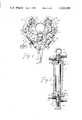
- FIG. 1is a top plan view of a pipe and a spinner according to my invention with the valve manifold schematically represented by dashed lines.
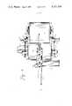
- FIG. 2is a sectional view of the spinner, taken substantially on line 2--2 of FIG. 4.
- FIG. 3is a sectional view of a pivot taken substantially on line 3--3 of FIG. 1.
- FIG. 4is a side elevational view of the spinner.
- a pipe spinnerthe main purpose of which is to spin pipe P.
- the main structural feature of the spinneris yoke 10.
- the yoke 10has the central area 12 from which projects right leg 14 and left leg 16.
- the main yokeis constructed to top plate 18 and bottom plate 20 having the shape as seen in FIGS. 1 and 2.
- the platesare thickened at the end of the legs for forming the pivots 22.
- the top and bottom platesare spaced apart by reinforced spacers 24.
- These reinforced spacersare mainly made from segments of casing, i.e., segments of a cylinder. Some plates are used in making the reinforced spacers 24.
- the main yoke 10is basically open, the inside or front or pipe side of the yoke to receive main roller 26, the right roller 28 and the left roller 30.
- torque tab 32Extending to the rear or outside of the main yoke to the central area is torque tab 32. It may be seen that the torque tab is made of a plate which is halfway between the top and bottom plates 18 and 20 (FIG. 4). Torque arm (not shown in FIG. 2 for clarity) 34 is bolted to the torque tab and has hole 36 in the end thereof for attaching a chain to the torque arm for exerting a torque upon the pipe spinner and, thus, the pipe P.
- Swing arm 38is attached to each pivot.
- Each swing armalso has top plate 40 and bottom plate 42 connected together by reinforced spacer 44.
- pivot block 46extends in the swing arms between the top plate 40 and the bottom plate 42. The pivot block 46 fits within the end of the heavy plates 22 on the end of each leg.
- Pivot shaft 48extends through the hole in the thickened plate 22 on the end of the legs and through the pivot block 46.
- the swing arms 38have cylinder ear 50 extending halfway between the top and bottom plates 40 and 42 and parallel thereto. Hydraulic cylinder 52 is attached to the torque tab 32. Hydraulic rod 54 extending from the hydraulic cylinder is attached to the cylinder ear 50.
- Arm rotary hydraulic motor 56is attached between the top and bottom plate 40 and 42 of each swing arm 38. As may be seen on the drawing, the axis of the hydraulic motor, the axis of the pivot and the axis of the cylinder ear pin 58 are aligned and parallel. Also, the outer housing of the arm rotary hydraulic motor 56 has the rollers 28 and 30 coaxially thereabout.
- Central rotary hydraulic motor 60is attached at the central area 12 of the yoke 10 between the top and bottom plates 18 and 20.
- the central hydraulic motoris co-axial with the central or main roller 26 which is thereabout.
- the axis of the central hydraulic motoris parallel to the axis of the arm rotary hydraulic motors 56 and obviously in use will also be parallel to the pipe P.
- the left swing arm 38is shown to be held rigidly in place by link arm 62.
- link arm 62which is provided, has clevis 64 which attaches to the torque tab 32.
- Turnbuckle 66extends between the clevis 64 and adjustment plate 68.
- the adjustment plateas may be seen, has a plurality of holes.
- the three rotary motors, 56 and 60each have roller 26, 28 or 30 therearound.
- the rollersall have urethane coating on the exterior thereof to provide a tough friction contact with the pipe P.
- Valve mounting plate 70is attached to the left leg 16.
- Valve console 72is attached thereto.
- the function of the valve consoleis to receive hydraulic fluid under pressure from source 74 of hydraulic fluid under pressure and selectively actuate a height adjustment cylinder (not shown) or the hydraulic cylinder 52 or to operate the rotary hydraulic motors 56 or 60 either forward, reverse or neutral.
- a height adjustment cylindernot shown
- the hydraulic cylinder 52includes a load lock so that the hydraulic cylinder may be locked in any position desired.
- the hydraulic cylindercan be extended so that the pipe P is firmly clamped between the three rollers 26, 28 and 30 and the cylinder 52 locked into position so that it remains tightly locked therein with sufficient pressure so that there is sufficient friction between the pipe and the rollers to spin the pipe upon actuation of the rotary motors 56 and 60.
- the fluid conduits 76connects the valve console to the hydraulic cylinder 52.
- Each of the rotary motorshas an axial inlet fluid connection 78 at the top thereof for receiving hydraulic fluid under pressure. Also, each of the rotary motors 56 and 60 have an axial outlet fluid connection 80 at the bottom thereof.
- Manifold 82is attached on the top of the fluid inlet connection 78 of the central motor 60.
- Fluid conduit 84supplies fluid under pressure from the valve console 72 to the manifold 82.
- the manifold 82provides fluid to the inlet of the motor 60 and also provides fluid to right conduit 86 and left conduit 88.
- Right fluid conduitextends along right leg 14 to the hydraulic swivel 90 on the pivot at the right leg.
- left fluid conduit 88extends along the left leg to the hydraulic swivel 90 on that pivot.
- Each hydraulic pivotincludes tubular body 92 (FIG. 3). The body has a fixed housing 94 attached thereto and a rotatable housing 96 attached thereto.
- the fluid conduits 86 and 88are attached to the fixed housing 94 and arm fluid conduits 98 connect the rotatable housing 96 to the inlet 78 of the arm rotary hydraulic motor 56. Therefore, it may be seen that a flexible connection has been made at the pivot point to supply hydraulic fluid under pressure to the arm rotary hydraulic motors.
- the axial outlet fluid connection 80 of each of the arm hydraulic motors 56is connected through a hydraulic swivel 90 to manifold 82 on the bottom of the central hydraulic motor and from that manifold by outlet fluid conduit 100 to the valve console 72.
- Front arm or front lifting eye 102has its shank extending through the hydraulic swivel tubular body 92 and screwed into a tapped hole in the top of thepivot shaft 48 (FIG. 3).
- Arm or front foot 104is attached by front foot shaft 106 through tubular body 92 of hydraulic swivel 90 on the bottom of pivot shaft 48.
- the front foot shaftis also threaded into a tapped hole in the bottom of the pivot shaft 48.
- Yoke or back lifting eye 108is attached to the rear of torque tab 32.
- rear foot 110is attached to the bottom of the rear of torque tab 32.
- the pipe spinnermay be placed upon a floor and supported by the three feet 104 and 110 or that by use of bridle (not shown) connected from eyes 102 and 108 to the height adjustment cylinder (not shown), the pipe spinner may be hoisted to a desirable height.
Landscapes
- Engineering & Computer Science (AREA)
- Life Sciences & Earth Sciences (AREA)
- Geology (AREA)
- Mining & Mineral Resources (AREA)
- Mechanical Engineering (AREA)
- Physics & Mathematics (AREA)
- Environmental & Geological Engineering (AREA)
- Fluid Mechanics (AREA)
- General Life Sciences & Earth Sciences (AREA)
- Geochemistry & Mineralogy (AREA)
- Hydraulic Motors (AREA)
Abstract
Description
(1) Field of the Invention
This invention relates to tools and more particularly to a machine wrench for round work.
(2) Description of the Prior Art
In the drilling of oil wells, and other oil field work, it is often necessary to run pipe or drill stem in and out of the well. In drilling wells, when it is necessary to remove the drill stem from the well, one or more sections of drill stem are pulled from the well and the joint "broken" or initially loosened by tongs. Thereafter, the sections are spun loose to completely disconnect the joint. The disconnected joint or joints are then moved to one side and another section or sections are lifted from the well.
Basically, the same steps are performed in reverse to place pipe or drill stem in a well.
Oil drilling industry requires extremely rugged equipment not only are the loads and the forces on the equipment very great, but also because of the urgent need to operate the equipment often times it receives rough handling in being roughly used and the equipment itself dropped or sometimes other pieces of equipment dropped upon top of it.
A traditional way of spinning the drill stem or the pipe is to wrap a chain around the pipe and then pull the chain, thereby spinning the pipe.
It will be understood that often times the drill stem or pipe is stressed to near its limit. Therefore, it is desirable not to damage the surface of the pipe inasmuch as this in itself will inherently weaken the point where toothed jaws bite deeply into the pipe. Furthermore, often the pipe is coated to prevent corrosion or damage.
Many of the prior art devices engage the pipe for spinning with toothed jaws or chains which tend to damage the surface of the pipe being spun.
Before this patent application was filed, a search was made in the United States Patent and Trademark Office which showed the following patents:
Mason U.S. Pat. No. 3,086,413
Wilson et al. U.S. Pat. No. 3,122,211
Campbell U.S. Pat. No. 3,380,323
Duke et al. U.S. Pat. No. 3,521,509
WILSON ET AL. discloses a pipe spinner for such use. The spinner spins the pipe by three rollers bearing against the pipe, one of which is hydraulically actuated against the pipe. The three rollers are driven by a chain drive from a single hydraulic rotary motor.
It appears that the other three patents are no more pertinent than the WILSON ET AL. patent.
(1) New and Different Function
I have invented a pipe spinner which is extremely compact and light in weight yet rugged and able to withstand the rough treatment that equipment of this nature may be expected to receive.
Specifically, I have achieved this by having each roller driven by a hydraulic rotary motor co-axial with the roller and mounted within the roller. In this manner, I can provide the necessary torque for the three rollers and not have the weight of chain drives to the three rollers together with the necessary support required by the three rollers. The equipment also has the advantage over other type equipment using chains or jaws to engage the pipe inasmuch as the pipe is not damaged.
Further, I have found that by coating the rollers with a urethane resin coating it gives a very good contact between the rollers and the pipe yet is a very tough coating on the rollers with no damage to the pipe.
Therefore, it may be seen that I have invented an improved pipe spinner, the total function of which far exceeds the sum of the functions of the individual motors, rollers, pivots and other elements.
(2) Objects of this Invention
An object of this invention is to spin pipe.
Further objects are to achieve the above with a device that is sturdy, compact, durable, lightweight, simple, safe, efficient, versatile, ecologically compatible, energy conserving, and reliable, yet inexpensive and easy to manufacture, adjust, operate and maintain.
Other objects are to achieve the above with a method that is versatile, ecologically compatible, energy conserving, rapid, efficient, and inexpensive, and does not require highly skilled people to adjust, operate, and maintain.
The specific nature of the invention, as well as other objects, uses, and advantages thereof, will clearly appear from the following description and from the accompanying drawing.
FIG. 1 is a top plan view of a pipe and a spinner according to my invention with the valve manifold schematically represented by dashed lines.
FIG. 2 is a sectional view of the spinner, taken substantially online 2--2 of FIG. 4.
FIG. 3 is a sectional view of a pivot taken substantially online 3--3 of FIG. 1.
FIG. 4 is a side elevational view of the spinner.
Referring to the drawings, and more particularly to FIG. 1, there may be seen a pipe spinner, the main purpose of which is to spin pipe P. The main structural feature of the spinner isyoke 10. Theyoke 10 has thecentral area 12 from which projects right leg 14 andleft leg 16. The main yoke is constructed totop plate 18 andbottom plate 20 having the shape as seen in FIGS. 1 and 2. The plates are thickened at the end of the legs for forming thepivots 22.
The top and bottom plates are spaced apart by reinforcedspacers 24. These reinforced spacers are mainly made from segments of casing, i.e., segments of a cylinder. Some plates are used in making the reinforcedspacers 24. It will be noted that themain yoke 10 is basically open, the inside or front or pipe side of the yoke to receivemain roller 26, the right roller 28 and theleft roller 30.
Extending to the rear or outside of the main yoke to the central area istorque tab 32. It may be seen that the torque tab is made of a plate which is halfway between the top andbottom plates 18 and 20 (FIG. 4). Torque arm (not shown in FIG. 2 for clarity) 34 is bolted to the torque tab and hashole 36 in the end thereof for attaching a chain to the torque arm for exerting a torque upon the pipe spinner and, thus, the pipe P.
Arm rotaryhydraulic motor 56 is attached between the top andbottom plate swing arm 38. As may be seen on the drawing, the axis of the hydraulic motor, the axis of the pivot and the axis of the cylinder ear pin 58 are aligned and parallel. Also, the outer housing of the arm rotaryhydraulic motor 56 has therollers 28 and 30 coaxially thereabout.
Central rotaryhydraulic motor 60 is attached at thecentral area 12 of theyoke 10 between the top andbottom plates main roller 26 which is thereabout. The axis of the central hydraulic motor is parallel to the axis of the arm rotaryhydraulic motors 56 and obviously in use will also be parallel to the pipe P.
Theleft swing arm 38 is shown to be held rigidly in place bylink arm 62. Those skilled in the art will recognize that a second hydraulic cylinder identical tohydraulic cylinder 52 could be used. The use of two hydraulic cylinders have certain advantages and certain disadvantages and the operators of this equipment, realizing both the advantages and disadvantages, may choose as to whether to use thelink arm 62 or a secondhydraulic cylinder 52. The link arm, which is provided, has clevis 64 which attaches to thetorque tab 32.Turnbuckle 66 extends between theclevis 64 andadjustment plate 68. The adjustment plate, as may be seen, has a plurality of holes. By the use of selecting which holes in theadjustment plate 68 is pinnedcylinder ear 50 and the adjustment of theturnbuckle 66 of the roller may be positioned as desired.
As stated before, the three rotary motors, 56 and 60, each haveroller
Each of the rotary motors has an axialinlet fluid connection 78 at the top thereof for receiving hydraulic fluid under pressure. Also, each of therotary motors outlet fluid connection 80 at the bottom thereof.
Front arm orfront lifting eye 102 has its shank extending through the hydraulic swiveltubular body 92 and screwed into a tapped hole in the top of thepivot shaft 48 (FIG. 3). Arm orfront foot 104 is attached byfront foot shaft 106 throughtubular body 92 ofhydraulic swivel 90 on the bottom ofpivot shaft 48. The front foot shaft is also threaded into a tapped hole in the bottom of thepivot shaft 48.
Yoke or back liftingeye 108 is attached to the rear oftorque tab 32. Likewiserear foot 110 is attached to the bottom of the rear oftorque tab 32.
Those skilled in the art will understand that the pipe spinner may be placed upon a floor and supported by the threefeet eyes
Thus it may be seen that I have provided a pipe spinner which is compact, sturdy and flexible over a large range of pipe size.
The embodiment shown and described above is only exemplary. I do not claim to have invented all the parts, elements or steps described. Various modifications can be made in the construction, material, arrangement, and operation, and still be within the scope of my invention. The limits of the invention and the bounds of the patent protection are measured by and defined in the following claims. The restrictive description and drawing of the specific example above do not point out what an infringement of this patent would be, but are to enable the reader to make and use the invention.
As an aid to correlating the terms of the claims to the exemplary drawing, the following catalog of elements is provided:
______________________________________ Pipe -P 10yoke 62link arm 12 maincentral area 64 clevis 14right leg 66turnbuckle 16left leg 68adjustment plate 18top plate 70valve mounting plate 20bottom plate 72valve console 22 pivots 74source 24 reinforced spacers 76 fluid conduits (cylinder) 26main roller 78 axial inlet fluid connection 28right roller 80 axialoutlet fluid connection 30 leftroller 82manifold 32torque tab 84 fluid conduit (manifold inlet) 34torque arm 86right fluid conduit 36 hole 88 leftfluid conduit 38swing arm 90hydraulic swivel 40top plate 92tubular body 42bottom plate 94 fixedhousing 44 reinforcedspacer 96rotatable housing 46pivot block 98arm fluid conduits 48pivot shaft 100outlet fluid conduit 50cylinder ear 102front lifting eye 52hydraulic cylinder 104front foot 54hydraulic rod 106front foot shaft 56 armhydraulic motor 108 yoke or back lifting eye 58cylinder ear pin 110rear foot 60 central hydraulic motor ______________________________________
Claims (14)
1. A pipe spinner for spinning pipe comprising:
a. a main yoke having a central area,
b. a right leg angling forward and to the right of the central area,
c. a left leg angling forward and to the left of the central area,
d. a torque arm tab extending directly back from the central area,
e. a torque arm bolted to the torque arm tab,
f. a pivot at the extreme end of the right arm,
g. a pivot at the extreme end of the left arm,
h. a swing arm pivoted to each pivot,
j. said swing arm having an ear extending on the outside,
k. a rotary hydraulic motor on the pipe side of said swing arm,
m. a hydraulic cylinder having one end pinned to the torque arm tab and having a rod extending from the other end,
n. said rod pinned to the swing arm ear,
o. said tab pin, said ear pin, said pivot and said rotary motor axis all being parallel,
p. a rotary hydraulic motor at the central area of the yoke and the axis of all of said motors being parallel.
2. The invention as defined in claim 1 wherein
q. an adjustable link arm extends from said torque tab to said ear on the outside of one of said swing arms.
3. The invention as defined in claim 1 further comprising:
q. said yoke including a top plate and a bottom plate,
e. reinforcement spacers between said top plate and said bottom plate,
s. said swing arms including a top plate below said yoke plate and a bottom plate above said yoke bottom plate and reinforcement spacers therebetween.
4. The invention as defined in claim 1 further comprising:
q. each of said rotary motors having a fluid inlet on the top thereof co-axial therewith,
r. a fluid conduit extending from the swing arm rotary motors to the pivots,
s. said conduit being flexible at said pivot and said fluid conduit extending to the central area motor,
t. each of said rotary motors having a fluid outlet connection concentric therewith on the bottom of said pipe spinner,
u. a fluid outlet connection attached from each of the swing arm rotary motors to said pivot,
v. said outlet fluid connections being flexible at the pivot,
w. said fluid connections extending from said pivot to said central area motor,
x. a source of hydraulic fluid under pressure,
y. a valve manifold,
z. said source of hydraulic fluid under pressure connected to said valve manifold,
aa. said valve manifold being a means for selectively furnishing hydraulic fluid under pressure to said hydraulic cylinder and to said three rotary motors.
5. The invention as defined in claim 4 further comprising:
bb. a manifold mounted on the top and bottom of said central area rotary motor coaxial therewith,
cc. said manifold providing
(i) a connection to said valve means,
(ii) a fluid connection to said central area rotary motor,
(iii) a fluid connection to said right leg pivot, and
(iv) a fluid connection to said left leg pivot.
6. The inventin as defined in claim 4 wherein
bb. said fluid inlet and outlet conduits to the swing arm motors are connected to a swivel connection attached to said pivot thereby achieveing said flexibility.
7. The invention as defined in claim 1 further comprising:
q. the outside of all of said motors having a roller attached thereto,
r. a polyurethane coating on all of said rollers.
8. The invention as defined in claim 1 further comprising:
q. pivot pins at each pivot,
r. a front lifting eye attached to each of said pivots above said pivot pins co-axial therewith,
s. a rear lifting eye attached to said torque tab, whereby a bridle may be attached to said lifting eyes to lift said pipe spinner,
t. a rear support foot below said rear lifting eye,
u. a front support foot co-axial with each of said pivot pins, whereby the pipe spinner may be supported by said three feet.
9. The invention as defined in claim 8 further comprising:
v. the outside of all of said motors having a roller attached thereto,
w. a polyurethane coating on all of said rollers.
10. The invention as defined in claim 9 further comprising:
x. each of said rotary motors having a fluid inlet on the top thereof co-axial therewith,
y. a fluid conduit extending from the swing arm rotary motors to the pivots,
z. said conduit being flexible at said pivot and said fluid conduit extending to the central area motor,
aa. each of said rotary motors having a fluid outlet connection concentric therewith on the bottom of said pipe spinner,
bb. a fluid outlet connection attached from each of the swing arm rotary motors to said pivot,
cc. said outlet fluid connections being flexible at the pivot,
dd. said fluid connections extending from said pivot to said central area motor,
ee. a source of hydraulic fluid under pressure,
ff. a valve manifold,
gg. said source of hydraulic fluid under pressure connected to said valve manifold,
hh. said valve manifold being a means for selectively furnishing hydraulic fluid under pressure to said hydraulic cylinder and to said three rotary motors.
11. The invention as defined in claim 10 wherein
jj. said fluid inlet and outlet conduits to the swing arm motors are connected to a swivel connection attached to said pivot thereby achieveing said flexibility.
12. The invention as defined in claim 11 further comprising:
kk. a manifold mounted on the top and bottom of said central area rotary motor coaxial therewith,
mm. said manifold providing
(i) a connection to said valve means,
(ii) a fluid connection to said central area rotary motor,
(iii) a fluid connection to said right leg pivot, and
(iv) a fluid connection to said left leg pivot.
13. The invention as defined in claim 12 further comprising:
nn. said yoke including a top plate and a bottom plate,
oo. reinforcement spacers between said top plate and said bottom plate,
pp. said swing arms including a top plate below said yoke plate and a bottom plate above said yoke bottom plate and reinforcement spacers therebetween.
14. The invention as defined in claim 13 wherein
qq. an adjustable link arm extends from said torque tab to said ear on the outside of one of said swing arms.
Priority Applications (1)
| Application Number | Priority Date | Filing Date | Title |
|---|---|---|---|
| US05/967,586US4221269A (en) | 1978-12-08 | 1978-12-08 | Pipe spinner |
Applications Claiming Priority (1)
| Application Number | Priority Date | Filing Date | Title |
|---|---|---|---|
| US05/967,586US4221269A (en) | 1978-12-08 | 1978-12-08 | Pipe spinner |
Publications (1)
| Publication Number | Publication Date |
|---|---|
| US4221269Atrue US4221269A (en) | 1980-09-09 |
Family
ID=25513012
Family Applications (1)
| Application Number | Title | Priority Date | Filing Date |
|---|---|---|---|
| US05/967,586Expired - LifetimeUS4221269A (en) | 1978-12-08 | 1978-12-08 | Pipe spinner |
Country Status (1)
| Country | Link |
|---|---|
| US (1) | US4221269A (en) |
Cited By (107)
| Publication number | Priority date | Publication date | Assignee | Title |
|---|---|---|---|---|
| EP0068610A3 (en)* | 1981-06-24 | 1983-03-23 | Weatherford/Lamb, Inc. | A power spinner for rotating a kelly joint |
| US4446761A (en)* | 1981-04-24 | 1984-05-08 | Varco International, Inc. | Pipe spinning tool |
| US4681158A (en)* | 1982-10-07 | 1987-07-21 | Mobil Oil Corporation | Casing alignment tool |
| US4756538A (en)* | 1985-04-01 | 1988-07-12 | The Science and Technic Department of Dagang Petroleum Administration | Device for clamping drill pipe and the like in mouse hole pipe |
| US4984936A (en)* | 1988-07-19 | 1991-01-15 | Hitachi Construction Machinery Co., Ltd. | Stopper apparatus for rotary reaction force |
| US5351582A (en)* | 1992-09-04 | 1994-10-04 | Aldridge Electric Inc. | Pipe turning tool |
| US6065372A (en)* | 1998-06-02 | 2000-05-23 | Rauch; Vernon | Power wrench for drill pipe |
| US6431655B1 (en)* | 1999-10-18 | 2002-08-13 | Mantovanibenne S.R.L. | Breaker device for removing the tops of columns |
| US20020144575A1 (en)* | 1999-09-17 | 2002-10-10 | David Niven | Gripping or clamping mechanisms |
| US6598501B1 (en) | 1999-01-28 | 2003-07-29 | Weatherford/Lamb, Inc. | Apparatus and a method for facilitating the connection of pipes |
| US20030164276A1 (en)* | 2000-04-17 | 2003-09-04 | Weatherford/Lamb, Inc. | Top drive casing system |
| US20030221519A1 (en)* | 2000-03-14 | 2003-12-04 | Haugen David M. | Methods and apparatus for connecting tubulars while drilling |
| US6668684B2 (en) | 2000-03-14 | 2003-12-30 | Weatherford/Lamb, Inc. | Tong for wellbore operations |
| US6684737B1 (en) | 1999-01-28 | 2004-02-03 | Weatherford/Lamb, Inc. | Power tong |
| US20040045717A1 (en)* | 2002-09-05 | 2004-03-11 | Haugen David M. | Method and apparatus for reforming tubular connections |
| US6745646B1 (en) | 1999-07-29 | 2004-06-08 | Weatherford/Lamb, Inc. | Apparatus and method for facilitating the connection of pipes |
| US6776070B1 (en)* | 1999-05-02 | 2004-08-17 | Varco I/P, Inc | Iron roughneck |
| US6814149B2 (en) | 1999-11-26 | 2004-11-09 | Weatherford/Lamb, Inc. | Apparatus and method for positioning a tubular relative to a tong |
| US20040237726A1 (en)* | 2002-02-12 | 2004-12-02 | Schulze Beckinghausen Joerg E. | Tong |
| US6857487B2 (en) | 2002-12-30 | 2005-02-22 | Weatherford/Lamb, Inc. | Drilling with concentric strings of casing |
| US20050056122A1 (en)* | 2003-09-05 | 2005-03-17 | Jaroslav Belik | Drillpipe spinner |
| US20050061112A1 (en)* | 2003-09-19 | 2005-03-24 | Weatherford Lamb, Inc. | Adapter frame for a power frame |
| US20050077743A1 (en)* | 2003-10-08 | 2005-04-14 | Bernd-Georg Pietras | Tong assembly |
| US6896075B2 (en) | 2002-10-11 | 2005-05-24 | Weatherford/Lamb, Inc. | Apparatus and methods for drilling with casing |
| US6899186B2 (en) | 2002-12-13 | 2005-05-31 | Weatherford/Lamb, Inc. | Apparatus and method of drilling with casing |
| US6920808B2 (en)* | 2002-03-08 | 2005-07-26 | Vernon Rauch | Double-action power pipe wrench |
| US6953096B2 (en) | 2002-12-31 | 2005-10-11 | Weatherford/Lamb, Inc. | Expandable bit with secondary release device |
| GB2414207A (en)* | 2004-05-20 | 2005-11-23 | Weatherford Lamb | Methods and apparatus for rotating and connecting tubulars |
| US6994176B2 (en) | 2002-07-29 | 2006-02-07 | Weatherford/Lamb, Inc. | Adjustable rotating guides for spider or elevator |
| US7004264B2 (en) | 2002-03-16 | 2006-02-28 | Weatherford/Lamb, Inc. | Bore lining and drilling |
| US7013997B2 (en) | 1994-10-14 | 2006-03-21 | Weatherford/Lamb, Inc. | Methods and apparatus for cementing drill strings in place for one pass drilling and completion of oil and gas wells |
| US7028586B2 (en) | 2000-02-25 | 2006-04-18 | Weatherford/Lamb, Inc. | Apparatus and method relating to tongs, continous circulation and to safety slips |
| US7028585B2 (en) | 1999-11-26 | 2006-04-18 | Weatherford/Lamb, Inc. | Wrenching tong |
| US7036610B1 (en) | 1994-10-14 | 2006-05-02 | Weatherford / Lamb, Inc. | Apparatus and method for completing oil and gas wells |
| US7040420B2 (en) | 1994-10-14 | 2006-05-09 | Weatherford/Lamb, Inc. | Methods and apparatus for cementing drill strings in place for one pass drilling and completion of oil and gas wells |
| US7048050B2 (en) | 1994-10-14 | 2006-05-23 | Weatherford/Lamb, Inc. | Method and apparatus for cementing drill strings in place for one pass drilling and completion of oil and gas wells |
| US7073598B2 (en) | 2001-05-17 | 2006-07-11 | Weatherford/Lamb, Inc. | Apparatus and methods for tubular makeup interlock |
| US7090021B2 (en) | 1998-08-24 | 2006-08-15 | Bernd-Georg Pietras | Apparatus for connecting tublars using a top drive |
| US7090254B1 (en) | 1999-04-13 | 2006-08-15 | Bernd-Georg Pietras | Apparatus and method aligning tubulars |
| US7093675B2 (en) | 2000-08-01 | 2006-08-22 | Weatherford/Lamb, Inc. | Drilling method |
| US7096982B2 (en) | 2003-02-27 | 2006-08-29 | Weatherford/Lamb, Inc. | Drill shoe |
| US7100710B2 (en) | 1994-10-14 | 2006-09-05 | Weatherford/Lamb, Inc. | Methods and apparatus for cementing drill strings in place for one pass drilling and completion of oil and gas wells |
| US7100713B2 (en) | 2000-04-28 | 2006-09-05 | Weatherford/Lamb, Inc. | Expandable apparatus for drift and reaming borehole |
| US7108084B2 (en) | 1994-10-14 | 2006-09-19 | Weatherford/Lamb, Inc. | Methods and apparatus for cementing drill strings in place for one pass drilling and completion of oil and gas wells |
| US7117957B2 (en) | 1998-12-22 | 2006-10-10 | Weatherford/Lamb, Inc. | Methods for drilling and lining a wellbore |
| US7128154B2 (en) | 2003-01-30 | 2006-10-31 | Weatherford/Lamb, Inc. | Single-direction cementing plug |
| US7128161B2 (en) | 1998-12-24 | 2006-10-31 | Weatherford/Lamb, Inc. | Apparatus and methods for facilitating the connection of tubulars using a top drive |
| US7137454B2 (en) | 1998-07-22 | 2006-11-21 | Weatherford/Lamb, Inc. | Apparatus for facilitating the connection of tubulars using a top drive |
| US7140445B2 (en) | 1997-09-02 | 2006-11-28 | Weatherford/Lamb, Inc. | Method and apparatus for drilling with casing |
| US7147068B2 (en) | 1994-10-14 | 2006-12-12 | Weatherford / Lamb, Inc. | Methods and apparatus for cementing drill strings in place for one pass drilling and completion of oil and gas wells |
| US7188687B2 (en) | 1998-12-22 | 2007-03-13 | Weatherford/Lamb, Inc. | Downhole filter |
| US7191840B2 (en) | 2003-03-05 | 2007-03-20 | Weatherford/Lamb, Inc. | Casing running and drilling system |
| US7213656B2 (en) | 1998-12-24 | 2007-05-08 | Weatherford/Lamb, Inc. | Apparatus and method for facilitating the connection of tubulars using a top drive |
| US7216727B2 (en) | 1999-12-22 | 2007-05-15 | Weatherford/Lamb, Inc. | Drilling bit for drilling while running casing |
| US7219744B2 (en) | 1998-08-24 | 2007-05-22 | Weatherford/Lamb, Inc. | Method and apparatus for connecting tubulars using a top drive |
| US7228901B2 (en) | 1994-10-14 | 2007-06-12 | Weatherford/Lamb, Inc. | Method and apparatus for cementing drill strings in place for one pass drilling and completion of oil and gas wells |
| US7264067B2 (en) | 2003-10-03 | 2007-09-04 | Weatherford/Lamb, Inc. | Method of drilling and completing multiple wellbores inside a single caisson |
| US7284617B2 (en) | 2004-05-20 | 2007-10-23 | Weatherford/Lamb, Inc. | Casing running head |
| US7303022B2 (en) | 2002-10-11 | 2007-12-04 | Weatherford/Lamb, Inc. | Wired casing |
| US7311148B2 (en) | 1999-02-25 | 2007-12-25 | Weatherford/Lamb, Inc. | Methods and apparatus for wellbore construction and completion |
| US7325610B2 (en) | 2000-04-17 | 2008-02-05 | Weatherford/Lamb, Inc. | Methods and apparatus for handling and drilling with tubulars or casing |
| US7334650B2 (en) | 2000-04-13 | 2008-02-26 | Weatherford/Lamb, Inc. | Apparatus and methods for drilling a wellbore using casing |
| US7360594B2 (en) | 2003-03-05 | 2008-04-22 | Weatherford/Lamb, Inc. | Drilling with casing latch |
| US7370707B2 (en) | 2003-04-04 | 2008-05-13 | Weatherford/Lamb, Inc. | Method and apparatus for handling wellbore tubulars |
| US7413020B2 (en) | 2003-03-05 | 2008-08-19 | Weatherford/Lamb, Inc. | Full bore lined wellbores |
| US20080202813A1 (en)* | 2007-02-27 | 2008-08-28 | Xtech Industries, Inc. | Mouse hole support unit with rotatable or stationary operation |
| US20080307932A1 (en)* | 2007-06-15 | 2008-12-18 | Longyear Tm, Inc. | Methods and apparatus for joint disassembly |
| US20090056931A1 (en)* | 2007-08-30 | 2009-03-05 | Longyear Tm, Inc. | Clamping and breaking device |
| US7503397B2 (en) | 2004-07-30 | 2009-03-17 | Weatherford/Lamb, Inc. | Apparatus and methods of setting and retrieving casing with drilling latch and bottom hole assembly |
| US7506564B2 (en) | 2002-02-12 | 2009-03-24 | Weatherford/Lamb, Inc. | Gripping system for a tong |
| US7509722B2 (en)* | 1997-09-02 | 2009-03-31 | Weatherford/Lamb, Inc. | Positioning and spinning device |
| US20090211404A1 (en)* | 2008-02-25 | 2009-08-27 | Jan Erik Pedersen | Spinning wrench systems |
| US20090277308A1 (en)* | 2008-05-12 | 2009-11-12 | Longyear Tm, Inc. | Open-faced rod spinner |
| US20090277626A1 (en)* | 2008-05-12 | 2009-11-12 | Keith William Littlely | Drill rod spinner device |
| US7617866B2 (en) | 1998-08-24 | 2009-11-17 | Weatherford/Lamb, Inc. | Methods and apparatus for connecting tubulars using a top drive |
| US7650944B1 (en) | 2003-07-11 | 2010-01-26 | Weatherford/Lamb, Inc. | Vessel for well intervention |
| US7669662B2 (en) | 1998-08-24 | 2010-03-02 | Weatherford/Lamb, Inc. | Casing feeder |
| US7694744B2 (en) | 2005-01-12 | 2010-04-13 | Weatherford/Lamb, Inc. | One-position fill-up and circulating tool and method |
| US7757759B2 (en) | 2006-04-27 | 2010-07-20 | Weatherford/Lamb, Inc. | Torque sub for use with top drive |
| US20100187740A1 (en)* | 2009-01-26 | 2010-07-29 | T&T Engineering Services | Pipe gripping apparatus |
| US7845418B2 (en) | 2005-01-18 | 2010-12-07 | Weatherford/Lamb, Inc. | Top drive torque booster |
| US7874352B2 (en) | 2003-03-05 | 2011-01-25 | Weatherford/Lamb, Inc. | Apparatus for gripping a tubular on a drilling rig |
| US7882902B2 (en) | 2006-11-17 | 2011-02-08 | Weatherford/Lamb, Inc. | Top drive interlock |
| EP2314827A2 (en) | 2005-12-23 | 2011-04-27 | National Oilwell Varco, L.P. | Apparatus and method for facilitating connecting and disconnecting members |
| USRE42877E1 (en) | 2003-02-07 | 2011-11-01 | Weatherford/Lamb, Inc. | Methods and apparatus for wellbore construction and completion |
| US8192129B1 (en) | 2007-10-24 | 2012-06-05 | T&T Engineering Services, Inc. | Pipe handling boom pretensioning apparatus |
| US8235104B1 (en)* | 2008-12-17 | 2012-08-07 | T&T Engineering Services, Inc. | Apparatus for pipe tong and spinner deployment |
| US8408334B1 (en) | 2008-12-11 | 2013-04-02 | T&T Engineering Services, Inc. | Stabbing apparatus and method |
| US8419335B1 (en) | 2007-10-24 | 2013-04-16 | T&T Engineering Services, Inc. | Pipe handling apparatus with stab frame stiffening |
| US8469648B2 (en) | 2007-10-24 | 2013-06-25 | T&T Engineering Services | Apparatus and method for pre-loading of a main rotating structural member |
| US8496238B1 (en) | 2009-01-26 | 2013-07-30 | T&T Engineering Services, Inc. | Tubular gripping apparatus with locking mechanism |
| US8550174B1 (en) | 2008-12-22 | 2013-10-08 | T&T Engineering Services, Inc. | Stabbing apparatus for centering tubulars and casings for connection at a wellhead |
| US8646522B1 (en) | 2009-01-26 | 2014-02-11 | T&T Engineering Services, Inc. | Method of gripping a tubular with a tubular gripping mechanism |
| US20140356120A1 (en)* | 2012-01-24 | 2014-12-04 | Quenton Seed | Rod loader attachment |
| US8905699B2 (en) | 2009-05-20 | 2014-12-09 | T&T Engineering Services, Inc. | Alignment apparatus and method for a boom of a pipe handling system |
| US9091128B1 (en) | 2011-11-18 | 2015-07-28 | T&T Engineering Services, Inc. | Drill floor mountable automated pipe racking system |
| CN104929545A (en)* | 2015-06-08 | 2015-09-23 | 湖南三一石油科技有限公司 | Automatic centering device and method for steel drilling tool |
| WO2015153591A1 (en)* | 2014-03-31 | 2015-10-08 | Hawk Industries, Inc. | Apparatus for rotating a pipe |
| US20150352677A1 (en)* | 2014-06-06 | 2015-12-10 | Glenn Guillot | Through Cutting Mill Steady Rest |
| US9476267B2 (en) | 2013-03-15 | 2016-10-25 | T&T Engineering Services, Inc. | System and method for raising and lowering a drill floor mountable automated pipe racking system |
| US9500049B1 (en) | 2008-12-11 | 2016-11-22 | Schlumberger Technology Corporation | Grip and vertical stab apparatus and method |
| US9556689B2 (en) | 2009-05-20 | 2017-01-31 | Schlumberger Technology Corporation | Alignment apparatus and method for a boom of a pipe handling system |
| US9593543B2 (en) | 2013-12-30 | 2017-03-14 | Bly Ip Inc. | Drill rod handling system for moving drill rods to and from an operative position |
| EP3141690A1 (en)* | 2015-09-11 | 2017-03-15 | Klemm Bohrtechnik GmbH | Drill pipe gripper |
| US10066451B2 (en) | 2015-12-22 | 2018-09-04 | Bly Ip Inc. | Drill rod clamping system and methods of using same |
| CN111535759A (en)* | 2020-04-30 | 2020-08-14 | 山东省地质矿产勘查开发局八〇一水文地质工程地质大队 | Pipeline interfacing apparatus is used in drilling of hydrogeological exploration |
| US11448018B2 (en)* | 2017-10-04 | 2022-09-20 | Eckel Manufacturing Co., Inc. | Power tong frame stiffner |
Citations (6)
| Publication number | Priority date | Publication date | Assignee | Title |
|---|---|---|---|---|
| US2746329A (en)* | 1953-02-06 | 1956-05-22 | Joy Mfg Co | Spinning device for drill pipe |
| US2928301A (en)* | 1957-07-18 | 1960-03-15 | Archie W Beeman | Power operated spinning devices for pipe |
| US2985455A (en)* | 1960-03-07 | 1961-05-23 | Vernon R Powell | Tube gripping mechanism |
| US3122211A (en)* | 1960-05-05 | 1964-02-25 | Wilson Mfg Co | Pipe spinning device |
| US3390726A (en)* | 1965-05-21 | 1968-07-02 | Deere & Co | Disk plow |
| US4099429A (en)* | 1972-03-27 | 1978-07-11 | Service Equipment Design Co., Inc. | Pipe-spinning apparatus and method |
- 1978
- 1978-12-08USUS05/967,586patent/US4221269A/ennot_activeExpired - Lifetime
Patent Citations (6)
| Publication number | Priority date | Publication date | Assignee | Title |
|---|---|---|---|---|
| US2746329A (en)* | 1953-02-06 | 1956-05-22 | Joy Mfg Co | Spinning device for drill pipe |
| US2928301A (en)* | 1957-07-18 | 1960-03-15 | Archie W Beeman | Power operated spinning devices for pipe |
| US2985455A (en)* | 1960-03-07 | 1961-05-23 | Vernon R Powell | Tube gripping mechanism |
| US3122211A (en)* | 1960-05-05 | 1964-02-25 | Wilson Mfg Co | Pipe spinning device |
| US3390726A (en)* | 1965-05-21 | 1968-07-02 | Deere & Co | Disk plow |
| US4099429A (en)* | 1972-03-27 | 1978-07-11 | Service Equipment Design Co., Inc. | Pipe-spinning apparatus and method |
Cited By (159)
| Publication number | Priority date | Publication date | Assignee | Title |
|---|---|---|---|---|
| US4446761A (en)* | 1981-04-24 | 1984-05-08 | Varco International, Inc. | Pipe spinning tool |
| EP0068610A3 (en)* | 1981-06-24 | 1983-03-23 | Weatherford/Lamb, Inc. | A power spinner for rotating a kelly joint |
| US4630688A (en)* | 1981-06-24 | 1986-12-23 | Weatherford/Lamb, Inc. | Power spinner for rotating a kelly joint |
| US4681158A (en)* | 1982-10-07 | 1987-07-21 | Mobil Oil Corporation | Casing alignment tool |
| US4756538A (en)* | 1985-04-01 | 1988-07-12 | The Science and Technic Department of Dagang Petroleum Administration | Device for clamping drill pipe and the like in mouse hole pipe |
| US4984936A (en)* | 1988-07-19 | 1991-01-15 | Hitachi Construction Machinery Co., Ltd. | Stopper apparatus for rotary reaction force |
| US5351582A (en)* | 1992-09-04 | 1994-10-04 | Aldridge Electric Inc. | Pipe turning tool |
| US7036610B1 (en) | 1994-10-14 | 2006-05-02 | Weatherford / Lamb, Inc. | Apparatus and method for completing oil and gas wells |
| US7040420B2 (en) | 1994-10-14 | 2006-05-09 | Weatherford/Lamb, Inc. | Methods and apparatus for cementing drill strings in place for one pass drilling and completion of oil and gas wells |
| US7108084B2 (en) | 1994-10-14 | 2006-09-19 | Weatherford/Lamb, Inc. | Methods and apparatus for cementing drill strings in place for one pass drilling and completion of oil and gas wells |
| US7228901B2 (en) | 1994-10-14 | 2007-06-12 | Weatherford/Lamb, Inc. | Method and apparatus for cementing drill strings in place for one pass drilling and completion of oil and gas wells |
| US7147068B2 (en) | 1994-10-14 | 2006-12-12 | Weatherford / Lamb, Inc. | Methods and apparatus for cementing drill strings in place for one pass drilling and completion of oil and gas wells |
| US7165634B2 (en) | 1994-10-14 | 2007-01-23 | Weatherford/Lamb, Inc. | Method and apparatus for cementing drill strings in place for one pass drilling and completion of oil and gas wells |
| US7048050B2 (en) | 1994-10-14 | 2006-05-23 | Weatherford/Lamb, Inc. | Method and apparatus for cementing drill strings in place for one pass drilling and completion of oil and gas wells |
| US7100710B2 (en) | 1994-10-14 | 2006-09-05 | Weatherford/Lamb, Inc. | Methods and apparatus for cementing drill strings in place for one pass drilling and completion of oil and gas wells |
| US7013997B2 (en) | 1994-10-14 | 2006-03-21 | Weatherford/Lamb, Inc. | Methods and apparatus for cementing drill strings in place for one pass drilling and completion of oil and gas wells |
| US7140445B2 (en) | 1997-09-02 | 2006-11-28 | Weatherford/Lamb, Inc. | Method and apparatus for drilling with casing |
| US7509722B2 (en)* | 1997-09-02 | 2009-03-31 | Weatherford/Lamb, Inc. | Positioning and spinning device |
| US6065372A (en)* | 1998-06-02 | 2000-05-23 | Rauch; Vernon | Power wrench for drill pipe |
| US7665531B2 (en) | 1998-07-22 | 2010-02-23 | Weatherford/Lamb, Inc. | Apparatus for facilitating the connection of tubulars using a top drive |
| US7137454B2 (en) | 1998-07-22 | 2006-11-21 | Weatherford/Lamb, Inc. | Apparatus for facilitating the connection of tubulars using a top drive |
| US7451826B2 (en) | 1998-08-24 | 2008-11-18 | Weatherford/Lamb, Inc. | Apparatus for connecting tubulars using a top drive |
| US7219744B2 (en) | 1998-08-24 | 2007-05-22 | Weatherford/Lamb, Inc. | Method and apparatus for connecting tubulars using a top drive |
| US7513300B2 (en) | 1998-08-24 | 2009-04-07 | Weatherford/Lamb, Inc. | Casing running and drilling system |
| US7669662B2 (en) | 1998-08-24 | 2010-03-02 | Weatherford/Lamb, Inc. | Casing feeder |
| US7617866B2 (en) | 1998-08-24 | 2009-11-17 | Weatherford/Lamb, Inc. | Methods and apparatus for connecting tubulars using a top drive |
| US7353880B2 (en) | 1998-08-24 | 2008-04-08 | Weatherford/Lamb, Inc. | Method and apparatus for connecting tubulars using a top drive |
| US7090021B2 (en) | 1998-08-24 | 2006-08-15 | Bernd-Georg Pietras | Apparatus for connecting tublars using a top drive |
| US7188687B2 (en) | 1998-12-22 | 2007-03-13 | Weatherford/Lamb, Inc. | Downhole filter |
| US7117957B2 (en) | 1998-12-22 | 2006-10-10 | Weatherford/Lamb, Inc. | Methods for drilling and lining a wellbore |
| US7128161B2 (en) | 1998-12-24 | 2006-10-31 | Weatherford/Lamb, Inc. | Apparatus and methods for facilitating the connection of tubulars using a top drive |
| US7213656B2 (en) | 1998-12-24 | 2007-05-08 | Weatherford/Lamb, Inc. | Apparatus and method for facilitating the connection of tubulars using a top drive |
| US6598501B1 (en) | 1999-01-28 | 2003-07-29 | Weatherford/Lamb, Inc. | Apparatus and a method for facilitating the connection of pipes |
| US6684737B1 (en) | 1999-01-28 | 2004-02-03 | Weatherford/Lamb, Inc. | Power tong |
| US7311148B2 (en) | 1999-02-25 | 2007-12-25 | Weatherford/Lamb, Inc. | Methods and apparatus for wellbore construction and completion |
| US7090254B1 (en) | 1999-04-13 | 2006-08-15 | Bernd-Georg Pietras | Apparatus and method aligning tubulars |
| US6776070B1 (en)* | 1999-05-02 | 2004-08-17 | Varco I/P, Inc | Iron roughneck |
| US6745646B1 (en) | 1999-07-29 | 2004-06-08 | Weatherford/Lamb, Inc. | Apparatus and method for facilitating the connection of pipes |
| US8186246B2 (en) | 1999-09-17 | 2012-05-29 | Weatherford/Lamb, Inc. | Gripping or clamping mechanisms |
| US20050160881A1 (en)* | 1999-09-17 | 2005-07-28 | Weatherford/Lamb, Inc. | Gripping or clamping mechanisms |
| US20020144575A1 (en)* | 1999-09-17 | 2002-10-10 | David Niven | Gripping or clamping mechanisms |
| US6431655B1 (en)* | 1999-10-18 | 2002-08-13 | Mantovanibenne S.R.L. | Breaker device for removing the tops of columns |
| US20060179980A1 (en)* | 1999-11-26 | 2006-08-17 | Weatherford/Lamb, Inc. | Wrenching tong |
| US7028585B2 (en) | 1999-11-26 | 2006-04-18 | Weatherford/Lamb, Inc. | Wrenching tong |
| US6814149B2 (en) | 1999-11-26 | 2004-11-09 | Weatherford/Lamb, Inc. | Apparatus and method for positioning a tubular relative to a tong |
| US7861618B2 (en) | 1999-11-26 | 2011-01-04 | Weatherford/Lamb, Inc. | Wrenching tong |
| US7216727B2 (en) | 1999-12-22 | 2007-05-15 | Weatherford/Lamb, Inc. | Drilling bit for drilling while running casing |
| US7028586B2 (en) | 2000-02-25 | 2006-04-18 | Weatherford/Lamb, Inc. | Apparatus and method relating to tongs, continous circulation and to safety slips |
| US20040154835A1 (en)* | 2000-03-14 | 2004-08-12 | Weatherford/Lamb, Inc. | Tong for wellbore operations |
| US7028787B2 (en) | 2000-03-14 | 2006-04-18 | Weatherford/Lamb, Inc. | Tong for wellbore operations |
| US20030221519A1 (en)* | 2000-03-14 | 2003-12-04 | Haugen David M. | Methods and apparatus for connecting tubulars while drilling |
| US6668684B2 (en) | 2000-03-14 | 2003-12-30 | Weatherford/Lamb, Inc. | Tong for wellbore operations |
| US7107875B2 (en) | 2000-03-14 | 2006-09-19 | Weatherford/Lamb, Inc. | Methods and apparatus for connecting tubulars while drilling |
| US7334650B2 (en) | 2000-04-13 | 2008-02-26 | Weatherford/Lamb, Inc. | Apparatus and methods for drilling a wellbore using casing |
| US7793719B2 (en) | 2000-04-17 | 2010-09-14 | Weatherford/Lamb, Inc. | Top drive casing system |
| US20030164276A1 (en)* | 2000-04-17 | 2003-09-04 | Weatherford/Lamb, Inc. | Top drive casing system |
| US7654325B2 (en) | 2000-04-17 | 2010-02-02 | Weatherford/Lamb, Inc. | Methods and apparatus for handling and drilling with tubulars or casing |
| US7325610B2 (en) | 2000-04-17 | 2008-02-05 | Weatherford/Lamb, Inc. | Methods and apparatus for handling and drilling with tubulars or casing |
| US7712523B2 (en) | 2000-04-17 | 2010-05-11 | Weatherford/Lamb, Inc. | Top drive casing system |
| US7918273B2 (en) | 2000-04-17 | 2011-04-05 | Weatherford/Lamb, Inc. | Top drive casing system |
| US7100713B2 (en) | 2000-04-28 | 2006-09-05 | Weatherford/Lamb, Inc. | Expandable apparatus for drift and reaming borehole |
| US7093675B2 (en) | 2000-08-01 | 2006-08-22 | Weatherford/Lamb, Inc. | Drilling method |
| US20110226486A1 (en)* | 2001-05-17 | 2011-09-22 | Haugen David M | Apparatus and methods for tubular makeup interlock |
| US8251151B2 (en) | 2001-05-17 | 2012-08-28 | Weatherford/Lamb, Inc. | Apparatus and methods for tubular makeup interlock |
| US7896084B2 (en) | 2001-05-17 | 2011-03-01 | Weatherford/Lamb, Inc. | Apparatus and methods for tubular makeup interlock |
| US7073598B2 (en) | 2001-05-17 | 2006-07-11 | Weatherford/Lamb, Inc. | Apparatus and methods for tubular makeup interlock |
| US8517090B2 (en) | 2001-05-17 | 2013-08-27 | Weatherford/Lamb, Inc. | Apparatus and methods for tubular makeup interlock |
| US7281587B2 (en) | 2001-05-17 | 2007-10-16 | Weatherford/Lamb, Inc. | Apparatus and methods for tubular makeup interlock |
| US20040237726A1 (en)* | 2002-02-12 | 2004-12-02 | Schulze Beckinghausen Joerg E. | Tong |
| US7506564B2 (en) | 2002-02-12 | 2009-03-24 | Weatherford/Lamb, Inc. | Gripping system for a tong |
| US7281451B2 (en) | 2002-02-12 | 2007-10-16 | Weatherford/Lamb, Inc. | Tong |
| US6920808B2 (en)* | 2002-03-08 | 2005-07-26 | Vernon Rauch | Double-action power pipe wrench |
| US7004264B2 (en) | 2002-03-16 | 2006-02-28 | Weatherford/Lamb, Inc. | Bore lining and drilling |
| US6994176B2 (en) | 2002-07-29 | 2006-02-07 | Weatherford/Lamb, Inc. | Adjustable rotating guides for spider or elevator |
| US7448456B2 (en) | 2002-07-29 | 2008-11-11 | Weatherford/Lamb, Inc. | Adjustable rotating guides for spider or elevator |
| US20040045717A1 (en)* | 2002-09-05 | 2004-03-11 | Haugen David M. | Method and apparatus for reforming tubular connections |
| US7100697B2 (en) | 2002-09-05 | 2006-09-05 | Weatherford/Lamb, Inc. | Method and apparatus for reforming tubular connections |
| US7303022B2 (en) | 2002-10-11 | 2007-12-04 | Weatherford/Lamb, Inc. | Wired casing |
| US7090023B2 (en) | 2002-10-11 | 2006-08-15 | Weatherford/Lamb, Inc. | Apparatus and methods for drilling with casing |
| US6896075B2 (en) | 2002-10-11 | 2005-05-24 | Weatherford/Lamb, Inc. | Apparatus and methods for drilling with casing |
| US6899186B2 (en) | 2002-12-13 | 2005-05-31 | Weatherford/Lamb, Inc. | Apparatus and method of drilling with casing |
| US7083005B2 (en) | 2002-12-13 | 2006-08-01 | Weatherford/Lamb, Inc. | Apparatus and method of drilling with casing |
| US7131505B2 (en) | 2002-12-30 | 2006-11-07 | Weatherford/Lamb, Inc. | Drilling with concentric strings of casing |
| US6857487B2 (en) | 2002-12-30 | 2005-02-22 | Weatherford/Lamb, Inc. | Drilling with concentric strings of casing |
| US6953096B2 (en) | 2002-12-31 | 2005-10-11 | Weatherford/Lamb, Inc. | Expandable bit with secondary release device |
| US7128154B2 (en) | 2003-01-30 | 2006-10-31 | Weatherford/Lamb, Inc. | Single-direction cementing plug |
| USRE42877E1 (en) | 2003-02-07 | 2011-11-01 | Weatherford/Lamb, Inc. | Methods and apparatus for wellbore construction and completion |
| US7096982B2 (en) | 2003-02-27 | 2006-08-29 | Weatherford/Lamb, Inc. | Drill shoe |
| US7413020B2 (en) | 2003-03-05 | 2008-08-19 | Weatherford/Lamb, Inc. | Full bore lined wellbores |
| US7874352B2 (en) | 2003-03-05 | 2011-01-25 | Weatherford/Lamb, Inc. | Apparatus for gripping a tubular on a drilling rig |
| US7191840B2 (en) | 2003-03-05 | 2007-03-20 | Weatherford/Lamb, Inc. | Casing running and drilling system |
| US8567512B2 (en) | 2003-03-05 | 2013-10-29 | Weatherford/Lamb, Inc. | Apparatus for gripping a tubular on a drilling rig |
| US10138690B2 (en) | 2003-03-05 | 2018-11-27 | Weatherford Technology Holdings, Llc | Apparatus for gripping a tubular on a drilling rig |
| US7360594B2 (en) | 2003-03-05 | 2008-04-22 | Weatherford/Lamb, Inc. | Drilling with casing latch |
| US7370707B2 (en) | 2003-04-04 | 2008-05-13 | Weatherford/Lamb, Inc. | Method and apparatus for handling wellbore tubulars |
| US7650944B1 (en) | 2003-07-11 | 2010-01-26 | Weatherford/Lamb, Inc. | Vessel for well intervention |
| WO2005026492A3 (en)* | 2003-09-05 | 2005-08-25 | Nat Oilwell Lp | Drillpipe spinner |
| US20050056122A1 (en)* | 2003-09-05 | 2005-03-17 | Jaroslav Belik | Drillpipe spinner |
| US7000502B2 (en)* | 2003-09-05 | 2006-02-21 | National-Ollwell | Drillpipe spinner |
| US7188548B2 (en) | 2003-09-19 | 2007-03-13 | Weatherford/Lamb, Inc. | Adapter frame for a power frame |
| US20050061112A1 (en)* | 2003-09-19 | 2005-03-24 | Weatherford Lamb, Inc. | Adapter frame for a power frame |
| US7264067B2 (en) | 2003-10-03 | 2007-09-04 | Weatherford/Lamb, Inc. | Method of drilling and completing multiple wellbores inside a single caisson |
| US20050077743A1 (en)* | 2003-10-08 | 2005-04-14 | Bernd-Georg Pietras | Tong assembly |
| US7707914B2 (en) | 2003-10-08 | 2010-05-04 | Weatherford/Lamb, Inc. | Apparatus and methods for connecting tubulars |
| GB2414207B (en)* | 2004-05-20 | 2009-11-25 | Weatherford Lamb | Apparatus and methods for connecting tubulars |
| US7284617B2 (en) | 2004-05-20 | 2007-10-23 | Weatherford/Lamb, Inc. | Casing running head |
| GB2414207A (en)* | 2004-05-20 | 2005-11-23 | Weatherford Lamb | Methods and apparatus for rotating and connecting tubulars |
| US7503397B2 (en) | 2004-07-30 | 2009-03-17 | Weatherford/Lamb, Inc. | Apparatus and methods of setting and retrieving casing with drilling latch and bottom hole assembly |
| US7694744B2 (en) | 2005-01-12 | 2010-04-13 | Weatherford/Lamb, Inc. | One-position fill-up and circulating tool and method |
| US7845418B2 (en) | 2005-01-18 | 2010-12-07 | Weatherford/Lamb, Inc. | Top drive torque booster |
| EP2314827A2 (en) | 2005-12-23 | 2011-04-27 | National Oilwell Varco, L.P. | Apparatus and method for facilitating connecting and disconnecting members |
| US7757759B2 (en) | 2006-04-27 | 2010-07-20 | Weatherford/Lamb, Inc. | Torque sub for use with top drive |
| US7882902B2 (en) | 2006-11-17 | 2011-02-08 | Weatherford/Lamb, Inc. | Top drive interlock |
| US7832470B2 (en) | 2007-02-27 | 2010-11-16 | Xtech Industries, Inc. | Mouse hole support unit with rotatable or stationary operation |
| US20110056705A1 (en)* | 2007-02-27 | 2011-03-10 | Xtech Industries, Inc. | Mouse hole support unit with rotatable or stationary operation |
| US20080202813A1 (en)* | 2007-02-27 | 2008-08-28 | Xtech Industries, Inc. | Mouse hole support unit with rotatable or stationary operation |
| US8235105B2 (en) | 2007-02-27 | 2012-08-07 | Paul Anthony | Mouse hole support unit with rotatable or stationary operation |
| EP2287437A1 (en) | 2007-03-07 | 2011-02-23 | National Oilwell Varco, L.P. | Spinner apparatus |
| US7997166B2 (en) | 2007-06-15 | 2011-08-16 | Longyear Tm, Inc. | Methods and apparatus for joint disassembly |
| US20080307932A1 (en)* | 2007-06-15 | 2008-12-18 | Longyear Tm, Inc. | Methods and apparatus for joint disassembly |
| US20090056931A1 (en)* | 2007-08-30 | 2009-03-05 | Longyear Tm, Inc. | Clamping and breaking device |
| US7997167B2 (en) | 2007-08-30 | 2011-08-16 | Longyear Tm, Inc. | Clamping and breaking device |
| US8419335B1 (en) | 2007-10-24 | 2013-04-16 | T&T Engineering Services, Inc. | Pipe handling apparatus with stab frame stiffening |
| US8696288B2 (en) | 2007-10-24 | 2014-04-15 | T&T Engineering Services, Inc. | Pipe handling boom pretensioning apparatus |
| US8192129B1 (en) | 2007-10-24 | 2012-06-05 | T&T Engineering Services, Inc. | Pipe handling boom pretensioning apparatus |
| US8469648B2 (en) | 2007-10-24 | 2013-06-25 | T&T Engineering Services | Apparatus and method for pre-loading of a main rotating structural member |
| US20090211404A1 (en)* | 2008-02-25 | 2009-08-27 | Jan Erik Pedersen | Spinning wrench systems |
| US20090277308A1 (en)* | 2008-05-12 | 2009-11-12 | Longyear Tm, Inc. | Open-faced rod spinner |
| US8291791B2 (en) | 2008-05-12 | 2012-10-23 | Longyear Tm, Inc. | Open-faced rod spinning device |
| US20090277626A1 (en)* | 2008-05-12 | 2009-11-12 | Keith William Littlely | Drill rod spinner device |
| US8006590B2 (en) | 2008-05-12 | 2011-08-30 | Longyear Tm, Inc. | Open-faced rod spinner |
| US7849929B2 (en) | 2008-05-12 | 2010-12-14 | Longyear Tm, Inc. | Drill rod spinner device |
| US8408334B1 (en) | 2008-12-11 | 2013-04-02 | T&T Engineering Services, Inc. | Stabbing apparatus and method |
| US9500049B1 (en) | 2008-12-11 | 2016-11-22 | Schlumberger Technology Corporation | Grip and vertical stab apparatus and method |
| US8235104B1 (en)* | 2008-12-17 | 2012-08-07 | T&T Engineering Services, Inc. | Apparatus for pipe tong and spinner deployment |
| US8550174B1 (en) | 2008-12-22 | 2013-10-08 | T&T Engineering Services, Inc. | Stabbing apparatus for centering tubulars and casings for connection at a wellhead |
| US8474806B2 (en) | 2009-01-26 | 2013-07-02 | T&T Engineering Services, Inc. | Pipe gripping apparatus |
| US8496238B1 (en) | 2009-01-26 | 2013-07-30 | T&T Engineering Services, Inc. | Tubular gripping apparatus with locking mechanism |
| US8646522B1 (en) | 2009-01-26 | 2014-02-11 | T&T Engineering Services, Inc. | Method of gripping a tubular with a tubular gripping mechanism |
| US20100187740A1 (en)* | 2009-01-26 | 2010-07-29 | T&T Engineering Services | Pipe gripping apparatus |
| US8905699B2 (en) | 2009-05-20 | 2014-12-09 | T&T Engineering Services, Inc. | Alignment apparatus and method for a boom of a pipe handling system |
| US9556689B2 (en) | 2009-05-20 | 2017-01-31 | Schlumberger Technology Corporation | Alignment apparatus and method for a boom of a pipe handling system |
| US9091128B1 (en) | 2011-11-18 | 2015-07-28 | T&T Engineering Services, Inc. | Drill floor mountable automated pipe racking system |
| US9945193B1 (en) | 2011-11-18 | 2018-04-17 | Schlumberger Technology Corporation | Drill floor mountable automated pipe racking system |
| US20140356120A1 (en)* | 2012-01-24 | 2014-12-04 | Quenton Seed | Rod loader attachment |
| US9476267B2 (en) | 2013-03-15 | 2016-10-25 | T&T Engineering Services, Inc. | System and method for raising and lowering a drill floor mountable automated pipe racking system |
| US9593543B2 (en) | 2013-12-30 | 2017-03-14 | Bly Ip Inc. | Drill rod handling system for moving drill rods to and from an operative position |
| US10047576B2 (en) | 2013-12-30 | 2018-08-14 | Bly Ip Inc. | Drill rod handling system for moving drill rods to and from an operative position |
| WO2015153591A1 (en)* | 2014-03-31 | 2015-10-08 | Hawk Industries, Inc. | Apparatus for rotating a pipe |
| EP3126612A4 (en)* | 2014-03-31 | 2017-03-29 | Hawk Industries, Inc. | Apparatus for rotating a pipe |
| US9545704B2 (en)* | 2014-06-06 | 2017-01-17 | Glenn Guillot | Through cutting mill steady rest |
| US20150352677A1 (en)* | 2014-06-06 | 2015-12-10 | Glenn Guillot | Through Cutting Mill Steady Rest |
| CN104929545A (en)* | 2015-06-08 | 2015-09-23 | 湖南三一石油科技有限公司 | Automatic centering device and method for steel drilling tool |
| CN104929545B (en)* | 2015-06-08 | 2017-08-04 | 湖南三一石油科技有限公司 | The automatic alignment method of iron driller |
| EP3141690A1 (en)* | 2015-09-11 | 2017-03-15 | Klemm Bohrtechnik GmbH | Drill pipe gripper |
| US10066451B2 (en) | 2015-12-22 | 2018-09-04 | Bly Ip Inc. | Drill rod clamping system and methods of using same |
| US11448018B2 (en)* | 2017-10-04 | 2022-09-20 | Eckel Manufacturing Co., Inc. | Power tong frame stiffner |
| CN111535759A (en)* | 2020-04-30 | 2020-08-14 | 山东省地质矿产勘查开发局八〇一水文地质工程地质大队 | Pipeline interfacing apparatus is used in drilling of hydrogeological exploration |
| CN111535759B (en)* | 2020-04-30 | 2021-11-30 | 山东省地质矿产勘查开发局八〇一水文地质工程地质大队 | Pipeline interfacing apparatus is used in drilling of hydrogeological exploration |
Similar Documents
| Publication | Publication Date | Title |
|---|---|---|
| US4221269A (en) | Pipe spinner | |
| US3680412A (en) | Joint breakout mechanism | |
| DE69911809T2 (en) | DEVICE AND METHOD FOR FACILITATING THE CONNECTION OF TUBES USING A TOP DRIVE | |
| US20170088401A1 (en) | Method and apparatus for handling lift subs and other objects | |
| US5845708A (en) | Coiled tubing apparatus | |
| DE69908418T2 (en) | DEVICE AND METHOD FOR FACILITATING THE CONNECTION OF TUBES USING A TOP DRIVE | |
| DE60028425T2 (en) | Installation and removal device for pipes | |
| US2535054A (en) | Brush puller | |
| US3021739A (en) | Hydraulically controlled and operated power tong | |
| US4791999A (en) | Well drilling apparatus | |
| US4593584A (en) | Power tongs with improved hydraulic drive | |
| US3131586A (en) | Mechanism for making up and breaking out screw threaded joints of drill stem and pipe | |
| US7490814B2 (en) | Cable pulling machine | |
| US4727781A (en) | Supercharged power tongs | |
| US4519576A (en) | Oil well safety valve for use with drill pipe | |
| US3759564A (en) | Grapple | |
| US2950639A (en) | Power operated pipe wrench | |
| US8056639B2 (en) | Well string injection system and method | |
| US4200010A (en) | Power-operated drill pipe spinner and pipe tongs | |
| EP4141214B1 (en) | End effector for gripping and spinning pipes | |
| US9988863B2 (en) | Apparatus and method for connecting components | |
| US3194329A (en) | Hydraulic grab bucket | |
| US7685910B2 (en) | Reversible torque back-up tong | |
| US5267504A (en) | Rotary actuator with annular fluid coupling rotatably mounted to shaft | |
| US6260252B1 (en) | Method and apparatus for assembling or disassembling an installation present on a seabed |