US4219330A - Dental handpiece and rotor cartridge replacement assembly therefor - Google Patents
Dental handpiece and rotor cartridge replacement assembly thereforDownload PDFInfo
- Publication number
- US4219330A US4219330AUS05/944,171US94417178AUS4219330AUS 4219330 AUS4219330 AUS 4219330AUS 94417178 AUS94417178 AUS 94417178AUS 4219330 AUS4219330 AUS 4219330A
- Authority
- US
- United States
- Prior art keywords
- rotor
- subassembly
- side wall
- cup member
- flexible
- Prior art date
- Legal status (The legal status is an assumption and is not a legal conclusion. Google has not performed a legal analysis and makes no representation as to the accuracy of the status listed.)
- Expired - Lifetime
Links
- 229920003023plasticPolymers0.000claimsabstractdescription7
- 239000004033plasticSubstances0.000claimsabstractdescription7
- 230000000712assemblyEffects0.000claimsdescription14
- 238000000429assemblyMethods0.000claimsdescription14
- 229920002457flexible plasticPolymers0.000claimsdescription7
- 239000000463materialSubstances0.000claimsdescription6
- 230000006835compressionEffects0.000claims3
- 238000007906compressionMethods0.000claims3
- 238000010276constructionMethods0.000description4
- 230000007246mechanismEffects0.000description4
- 238000006073displacement reactionMethods0.000description3
- 238000003780insertionMethods0.000description3
- 230000037431insertionEffects0.000description3
- 230000005540biological transmissionEffects0.000description2
- 238000001816coolingMethods0.000description2
- 238000004519manufacturing processMethods0.000description2
- 230000036316preloadEffects0.000description2
- 239000004677NylonSubstances0.000description1
- 230000009471actionEffects0.000description1
- 238000007664blowingMethods0.000description1
- 238000005520cutting processMethods0.000description1
- 238000000605extractionMethods0.000description1
- 230000001050lubricating effectEffects0.000description1
- 229920001778nylonPolymers0.000description1
- 230000000737periodic effectEffects0.000description1
- 230000001681protective effectEffects0.000description1
- 230000009467reductionEffects0.000description1
- 230000000717retained effectEffects0.000description1
- 125000006850spacer groupChemical group0.000description1
- XLYOFNOQVPJJNP-UHFFFAOYSA-NwaterSubstancesOXLYOFNOQVPJJNP-UHFFFAOYSA-N0.000description1
Images


Classifications
- A—HUMAN NECESSITIES
- A61—MEDICAL OR VETERINARY SCIENCE; HYGIENE
- A61C—DENTISTRY; APPARATUS OR METHODS FOR ORAL OR DENTAL HYGIENE
- A61C1/00—Dental machines for boring or cutting ; General features of dental machines or apparatus, e.g. hand-piece design
- A61C1/08—Machine parts specially adapted for dentistry
- A61C1/18—Flexible shafts; Clutches or the like; Bearings or lubricating arrangements; Drives or transmissions
- A61C1/181—Bearings or lubricating arrangements, e.g. air-cushion bearings
- A—HUMAN NECESSITIES
- A61—MEDICAL OR VETERINARY SCIENCE; HYGIENE
- A61C—DENTISTRY; APPARATUS OR METHODS FOR ORAL OR DENTAL HYGIENE
- A61C1/00—Dental machines for boring or cutting ; General features of dental machines or apparatus, e.g. hand-piece design
- A61C1/02—Dental machines for boring or cutting ; General features of dental machines or apparatus, e.g. hand-piece design characterised by the drive of the dental tools
- A61C1/05—Dental machines for boring or cutting ; General features of dental machines or apparatus, e.g. hand-piece design characterised by the drive of the dental tools with turbine drive
- F—MECHANICAL ENGINEERING; LIGHTING; HEATING; WEAPONS; BLASTING
- F16—ENGINEERING ELEMENTS AND UNITS; GENERAL MEASURES FOR PRODUCING AND MAINTAINING EFFECTIVE FUNCTIONING OF MACHINES OR INSTALLATIONS; THERMAL INSULATION IN GENERAL
- F16C—SHAFTS; FLEXIBLE SHAFTS; ELEMENTS OR CRANKSHAFT MECHANISMS; ROTARY BODIES OTHER THAN GEARING ELEMENTS; BEARINGS
- F16C27/00—Elastic or yielding bearings or bearing supports, for exclusively rotary movement
- F16C27/06—Elastic or yielding bearings or bearing supports, for exclusively rotary movement by means of parts of rubber or like materials
- F16C27/066—Ball or roller bearings
- F—MECHANICAL ENGINEERING; LIGHTING; HEATING; WEAPONS; BLASTING
- F16—ENGINEERING ELEMENTS AND UNITS; GENERAL MEASURES FOR PRODUCING AND MAINTAINING EFFECTIVE FUNCTIONING OF MACHINES OR INSTALLATIONS; THERMAL INSULATION IN GENERAL
- F16C—SHAFTS; FLEXIBLE SHAFTS; ELEMENTS OR CRANKSHAFT MECHANISMS; ROTARY BODIES OTHER THAN GEARING ELEMENTS; BEARINGS
- F16C19/00—Bearings with rolling contact, for exclusively rotary movement
- F16C19/54—Systems consisting of a plurality of bearings with rolling friction
- F16C19/546—Systems with spaced apart rolling bearings including at least one angular contact bearing
- F16C19/547—Systems with spaced apart rolling bearings including at least one angular contact bearing with two angular contact rolling bearings
- F—MECHANICAL ENGINEERING; LIGHTING; HEATING; WEAPONS; BLASTING
- F16—ENGINEERING ELEMENTS AND UNITS; GENERAL MEASURES FOR PRODUCING AND MAINTAINING EFFECTIVE FUNCTIONING OF MACHINES OR INSTALLATIONS; THERMAL INSULATION IN GENERAL
- F16C—SHAFTS; FLEXIBLE SHAFTS; ELEMENTS OR CRANKSHAFT MECHANISMS; ROTARY BODIES OTHER THAN GEARING ELEMENTS; BEARINGS
- F16C2316/00—Apparatus in health or amusement
- F16C2316/10—Apparatus in health or amusement in medical appliances, e.g. in diagnosis, dentistry, instruments, prostheses, medical imaging appliances
- F16C2316/13—Dental machines
Definitions
- Such flexure of the cup's side wallis facilitated by a multiplicity of notches which are spaced circumferentially about the rim of the cup and which define a multiplicity of spring fingers formed integrally with the cup's side wall.
- the spring fingerssurround and retain the resilient support ring for the lower bearing assembly and, especially when the rotor cartridge or subassembly is mounted within the housing of a handpiece, such fingers exert a compressive force on the ring which serves to hold the cup, ring, and lower bearing assembly (along with other elements such as, for example, a wave washer) frictionally together.
- the security of such frictional engagementis increased by reason of the fact that the resilient ring tends to bulge or expand slightly into the notches of the cup, thereby reducing the possibility of independent relative movement of the parts.
- the rotor cartridge or subassemblyis part of a larger assembly which includes a housing cap and a support tool for holding the parts together during shipment and storage and for inserting and securing such parts in place when handpiece reconstruction is required.
- the toolincludes an enlarged upper retaining element in the form of a wrench which is keyed to the threaded handpiece cap so that, following insertion of the rotor subassembly into the cavity of the handpiece housing, the wrench may be rotated to secure the threaded cap in place.
- the toolalso includes a spindle which extends through both the cap and the rotor cartridge, and a lower retaining element in the form of a sleeve which is located at the lower end of the spindle and which holds the cap and cartridge in place upon that spindle until such time as removal is desired.
- a spindlewhich extends through both the cap and the rotor cartridge
- a lower retaining elementin the form of a sleeve which is located at the lower end of the spindle and which holds the cap and cartridge in place upon that spindle until such time as removal is desired.
- One of the retaining elementseither the wrench or sleeve, is removable from the spindle to permit extraction of the spindle after the replacement rotor assembly has been secured within the handpiece housing.
- the removable memberis the lower retaining element which takes the form of a plastic sleeve frictionally secured to the lower end of the spindle.
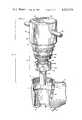
- FIG. 1is a fragmentary vertical sectional view showing the head housing of a contra angle handpiece equipped with the rotor assembly of this invention.
- FIG. 2is an enlarged vertical sectional view of a complete rotor cartridge replacement assembly.
- FIG. 4is an enlarged horizontal sectional view taken along line 4--4 of FIG. 2.
- the numeral 10designates the handle of a contra angle air-driven dental handpiece, the handle terminating in a head housing 11 having an enlarged threaded opening 12 at its upper end and a centrally apertured bottom wall 13 at its lower end.
- An externally threaded cap 14is secured to the upper end of the housing to retain the rotor "cartridge" 15 within the cavity 16 of the housing.
- carrierwill be used herein as a matter of convenience although it will become apparent as the specification proceeds that the parts so designated do not constitute a rigid unitary cartridge but are instead a subassembly of the basic components of the handpiece which are held securely together in operative relationship only when they are fully mounted in a handpiece as shown in FIG. 1.
- the handle of the handpieceincludes a tube 17 for delivering drive air to the operating mechanism.
- Tube 18carries chip-blowing air and 18a delivers water to the work area for cooling the bur and tooth during a cutting operation and for clearing chips from the work area.
- Exhaust air discharged from the turbinepasses into the handle through exhaust port 19.
- FIGS. 3 and 4depict the rotor subassembly or cartridge removed from head housing 11 and carried by a supporting tool 20 along with handpiece cap 14.
- the toolincludes a spindle 21 which extends axially through all of the components of the cartridge 15 and through end cap 14, an upper retaining element 22, and a lower retaining element 23.
- One of the retaining elementsis secured to the spindle while the other is only frictionally held in place and may be removed therefrom; in the preferred embodiment illustrated, the lower element 23, which takes the form of a resilient plastic sleeve, is removably fitted upon the lower end of the spindle while the upper retaining element 22, which takes the form of an enlarged cylindrical knob, is more permanently secured to the spindle's upper end.
- the cylindrical knob 22has a diameter greater than cap 14 and includes two (or more) eccentrically located pins 24 which extend beyond the knob and which are positioned to be received within sockets 25 in cap 14.
- the pinstherefore key the cap 14 and the supporting tool 20 against independent relative rotation so that the tool may be used as a torsion wrench to screw cap 14 into place.
- a transverse torque bar 26may extend through the cylindrical body 22 and project radially beyond that body to assist a user in applying the required force in tightening (or loosening) a handpiece cap 14. It will be noted that pins 24 project from the upper surface of cylindrical body 22 (FIG.
- the toolmay be used as a wrench to remove the old cap from an existing handpiece requiring replacement of its operating mechanism without disturbing the rotor subassembly supported on the opposite side of the wrench.
- the supporting tool 20, cap 14, and cartridge or rotor subassembly 15together form a unitary rotor cartridge replacement assembly designated generally by the numeral 27 in FIG. 3.
- the assembly 27represents all that is required to permit a user to replace the operating mechanism of an airdriven dental handpiece.
- the exposed stub ends of pins 24are used to engage and remove the existing cap from a handpiece requiring rotor replacement.
- the new rotor cartridge or subassembly 15is inserted into the cavity 16 of the housing in the manner depicted in FIG. 3.
- the new cap 14is screwed into place using tool 20 as a wrench.
- the resilient sleeve 23is removed from the lower end of the spindle (an action which may be achieved simply by lifting the tool by means of torque bar 26), and the tool is removed from the rebuilt handpiece.
- the rotor cartridge or subassembly 15comprises a turbine rotor 28, upper and lower bearing assemblies 29 and 30, resilient support rings 31 and 32 surrounding the outer races of the upper and lower ball bearing assemblies, respectively, a stator ring 33 having apertures 34 for directing drive air axially against the vanes 35 of the turbine, a cup-shaped member 36 surrounding the lower bearing assembly 30 and a resilient support ring 32, and a wave spring 37 for exerting an axial pre-load from the outer race of the lower bearing assembly and for urging the cup member 36 into properly seated condition within the cavity of the handpiece's head housing.
- Rotor 28includes a bur tube 28a which extends through a bore in turbine 28b, it being understood that, if desired, the turbine and bur tube may be integrally formed.
- a suitable chuck 38extends through the axial bore 39 of the bur tube and is threadedly adjustable within that bore for the purpose of clamping or releasing a dental bur (not shown) which in normal handpiece operation would be mounted within the bore 40 of the chuck.
- Bore 40including bore portion 40a, extends completely through the chuck and that bore, combined with the upper end of bur tube bore 39, together define an opening which extends axially and completely through rotor cartridge 15.
- Bore portion 40ais non-circular (square) in cross section to receive the non-circular shaft of a suitable wrench (not shown) used to apply torsional force to the chuck during tightening or loosening of the chuck.
- Cap 14is similarly provided with an opening 41 coaxial with opening 40.
- spindle 21may therefore extend axially through the central opening 41 and the openings 39 and 40 of bur tube 28a and chuck 38, respectively.
- the spindleis dimensioned to be loosely received in the passage or opening extending through the cartridge 15 and superimposed cap 14, such parts being retained on the spindle because of the cylindrical knob or body 22 which engages the top surface of the cap and the retaining sleeve 23 which engages the bottom surface of rotor 28.
- stator ring 33In the particular form of turbine illustrated in the drawings, air passes in a generally axial direction through the turbine blades, in contrast to a construction in which air impinges on the blades in a tangential or radial direction.
- the formerrequires a stator, as represented by stator ring 33, whereas in the latter cases, as in a Pelton wheel turbine, a stator may be unnecessary.
- a statoras such is not an essential element of the rotor cartridge subassembly unless an axial-flow of turbine of the general type depicted in the drawings is utilized.
- some meansmust be provided for retaining the upper resilient support ring 31 and, as shown in the drawings (FIG. 2), ring 33 also performs that function.
- Cup-shaped member 36is formed of a tough flexible plastic material such as nylon, although it is believed apparent that other materials having similar properties may also be used.
- the cupincludes a side wall 36a and an integral end or bottom wall 36b, the latter being provided with a central aperture 42 to accommodate the lower end of rotor 28 and to permit the escape of cooling (and lubricating) air passing through the lower bearing assembly 30 and wave washer 37.
- the outer corner of the cupis beveled or rounded at 43 (FIG. 2) and the side wall 36a has an outer surface which is slightly frusto conical in shape, sloping gradually upwardly and outwardly at an angle x within the range of about 1 to 5 degrees from the vertical.
- the cavity of the cupretains the wave washer or spring 37, the lower bearing assembly 30, and the resilient support ring 32.
- the sloping side wall of the cupis provided with a plurality of circumferentially-spaced notches which extend downwardly from the top of the cup to a level intermediate the upper and lower limits of side wall 36a. Such notches thereby define a plurality of upstanding flexible fingers 45 formed as integral parts of side wall 36a.
- Resilient ring 32is squeezed or tightly held between such fingers and the outer race of bearing assembly 30 with the result that portions of the ring expand or are forced limited distances into the notches between the fingers (FIG. 4).
- Such limited expansion of the resilient ring into the notchesassists in holding the ring in place, that is, in preventing relative movement between the resilient support ring 32 and the cup 36.
- Each finger 45 of the cupis provided with an inwardly projecting lip or flange 46 at its upper end for the purpose of retaining the resilient support ring 32 against upward axial displacement with respect to the cup. It will be observed, however, that the inner surfaces of the lips define an opening appreciably larger than the inside diameter of resilient support ring 32 (or the outside diameter of bearing assembly 30) so that no direct contact between the cup and bearing assembly occurs.
- the tapered cup 36performs important functions in helping to guide the lower end of a rotor cartridge replacement assembly into place within the cavity of the head housing of a dental handpiece, of protecting the resilient support ring 32 and spring washer 37 against displacement during such an insertion step, and of reducing the transmission of sound and virbration from the lower bearing assembly to the head housing during handpiece operation.
- the cupalso serves to protect the lower bearing assembly against forces which might otherwise cause slight misalignment of the upper and lower bearing assemblies, since fingers 45 are capable of flexing slightly to accommodate such differences and absorb such forces.
- the slightly frusto conical configuration of the cup's outer surfacepermits greater dimensional tolerances during manufacture while at the same time insuring that the cup will fit firmly and properly within the head cavity of a dental handpiece, thereby permitting a reduction in manufacturing and selling costs without reducing quality of construction or performance.
Landscapes
- Health & Medical Sciences (AREA)
- Oral & Maxillofacial Surgery (AREA)
- Dentistry (AREA)
- Epidemiology (AREA)
- Life Sciences & Earth Sciences (AREA)
- Animal Behavior & Ethology (AREA)
- General Health & Medical Sciences (AREA)
- Public Health (AREA)
- Veterinary Medicine (AREA)
- Engineering & Computer Science (AREA)
- General Engineering & Computer Science (AREA)
- Mechanical Engineering (AREA)
- Dental Tools And Instruments Or Auxiliary Dental Instruments (AREA)
Abstract
Description
Claims (20)
Priority Applications (4)
| Application Number | Priority Date | Filing Date | Title |
|---|---|---|---|
| US05/944,171US4219330A (en) | 1978-09-20 | 1978-09-20 | Dental handpiece and rotor cartridge replacement assembly therefor |
| PCT/US1979/000574WO1980000656A1 (en) | 1978-09-20 | 1979-08-06 | Dental handpiece and rotor cartridge replacement assembly therefor |
| JP54501589AJPS5741252B2 (en) | 1978-09-20 | 1979-08-06 | |
| EP19790901249EP0020450A4 (en) | 1978-09-20 | 1980-04-22 | Dental handpiece and rotor cartridge replacement assembly therefor. |
Applications Claiming Priority (1)
| Application Number | Priority Date | Filing Date | Title |
|---|---|---|---|
| US05/944,171US4219330A (en) | 1978-09-20 | 1978-09-20 | Dental handpiece and rotor cartridge replacement assembly therefor |
Publications (1)
| Publication Number | Publication Date |
|---|---|
| US4219330Atrue US4219330A (en) | 1980-08-26 |
Family
ID=25480933
Family Applications (1)
| Application Number | Title | Priority Date | Filing Date |
|---|---|---|---|
| US05/944,171Expired - LifetimeUS4219330A (en) | 1978-09-20 | 1978-09-20 | Dental handpiece and rotor cartridge replacement assembly therefor |
Country Status (4)
| Country | Link |
|---|---|
| US (1) | US4219330A (en) |
| EP (1) | EP0020450A4 (en) |
| JP (1) | JPS5741252B2 (en) |
| WO (1) | WO1980000656A1 (en) |
Cited By (13)
| Publication number | Priority date | Publication date | Assignee | Title |
|---|---|---|---|---|
| US4533324A (en)* | 1983-02-09 | 1985-08-06 | Nakanishi Dental Mfg., Co., Ltd. | Air driven dental handpiece |
| US5252067A (en)* | 1991-12-03 | 1993-10-12 | Ushio Co., Ltd. | Handpiece for dental medical treatment |
| US5423678A (en)* | 1993-05-20 | 1995-06-13 | Nakanishi Dental Mfg. Co., Ltd. | Handpiece having bearing protective member |
| WO1997040768A1 (en)* | 1996-04-29 | 1997-11-06 | Young Dental Manufacturing Co., Inc. | Autoclavable dental handpiece with disposable high speed turbine |
| US5733120A (en)* | 1994-11-25 | 1998-03-31 | Koyo Seiko Co., Ltd. | Dental handpiece capable of stable supporting turbine |
| US5772435A (en)* | 1995-12-05 | 1998-06-30 | Healthpoint, Ltd. | Dental and surgical handpiece with disposable cartridge |
| US5911579A (en)* | 1997-06-09 | 1999-06-15 | Nakanishi, Inc. | Dental handpiece with baffle for stabilizing rolling bearing cage |
| US5921777A (en)* | 1995-12-05 | 1999-07-13 | Healthpoint, Ltd. | Dental and surgical handpiece with disposable cartridge |
| EP1157671A1 (en)* | 2000-05-24 | 2001-11-28 | Sirona Dental Systems GmbH | Dental handpiece with devices for tensioning a grip-sleeve with a head part |
| US6579093B2 (en) | 2001-02-23 | 2003-06-17 | Young Dental Manufacturing Company 1, Llc | High speed turbine cartridge for use with a medical/dental handpiece |
| US20080070189A1 (en)* | 2002-12-20 | 2008-03-20 | Derek Turner | Dental handpiece |
| US20160008937A1 (en)* | 2013-03-06 | 2016-01-14 | Gerald Jay Sanders | Turbine driven power unit for a cutting tool |
| CN112618072A (en)* | 2020-12-31 | 2021-04-09 | 苏州迪凯尔医疗科技有限公司 | Cell phone clamp and dental planter |
Families Citing this family (2)
| Publication number | Priority date | Publication date | Assignee | Title |
|---|---|---|---|---|
| JPS60192576U (en)* | 1984-05-28 | 1985-12-20 | 三菱電機株式会社 | display monitor device |
| JPH0613039B2 (en)* | 1987-07-22 | 1994-02-23 | 而至歯科工業株式会社 | Checkless dental handpiece |
Citations (6)
| Publication number | Priority date | Publication date | Assignee | Title |
|---|---|---|---|---|
| US2945299A (en)* | 1957-08-22 | 1960-07-19 | Carroll S Fritz | Dental handpiece |
| US3298103A (en)* | 1958-01-03 | 1967-01-17 | Weber Dental Mfg Company | Fluid-driven dental handpiece construction |
| US3325899A (en)* | 1964-09-25 | 1967-06-20 | American Hospital Supply Corp | Dental handpiece and collet wrench therefor |
| US3376084A (en)* | 1965-01-07 | 1968-04-02 | Barden Corp | Dental handpiece |
| US3888008A (en)* | 1973-01-24 | 1975-06-10 | American Hospital Supply Corp | Handpiece and chuck wrench therefor |
| US4071954A (en)* | 1976-04-28 | 1978-02-07 | Kaltenbach & Voigt | Turbine insert for the head of a dental turbine elbow |
- 1978
- 1978-09-20USUS05/944,171patent/US4219330A/ennot_activeExpired - Lifetime
- 1979
- 1979-08-06JPJP54501589Apatent/JPS5741252B2/janot_activeExpired
- 1979-08-06WOPCT/US1979/000574patent/WO1980000656A1/enunknown
- 1980
- 1980-04-22EPEP19790901249patent/EP0020450A4/ennot_activeCeased
Patent Citations (6)
| Publication number | Priority date | Publication date | Assignee | Title |
|---|---|---|---|---|
| US2945299A (en)* | 1957-08-22 | 1960-07-19 | Carroll S Fritz | Dental handpiece |
| US3298103A (en)* | 1958-01-03 | 1967-01-17 | Weber Dental Mfg Company | Fluid-driven dental handpiece construction |
| US3325899A (en)* | 1964-09-25 | 1967-06-20 | American Hospital Supply Corp | Dental handpiece and collet wrench therefor |
| US3376084A (en)* | 1965-01-07 | 1968-04-02 | Barden Corp | Dental handpiece |
| US3888008A (en)* | 1973-01-24 | 1975-06-10 | American Hospital Supply Corp | Handpiece and chuck wrench therefor |
| US4071954A (en)* | 1976-04-28 | 1978-02-07 | Kaltenbach & Voigt | Turbine insert for the head of a dental turbine elbow |
Cited By (18)
| Publication number | Priority date | Publication date | Assignee | Title |
|---|---|---|---|---|
| US4533324A (en)* | 1983-02-09 | 1985-08-06 | Nakanishi Dental Mfg., Co., Ltd. | Air driven dental handpiece |
| US5252067A (en)* | 1991-12-03 | 1993-10-12 | Ushio Co., Ltd. | Handpiece for dental medical treatment |
| US5423678A (en)* | 1993-05-20 | 1995-06-13 | Nakanishi Dental Mfg. Co., Ltd. | Handpiece having bearing protective member |
| US5733120A (en)* | 1994-11-25 | 1998-03-31 | Koyo Seiko Co., Ltd. | Dental handpiece capable of stable supporting turbine |
| US5921777A (en)* | 1995-12-05 | 1999-07-13 | Healthpoint, Ltd. | Dental and surgical handpiece with disposable cartridge |
| US5772435A (en)* | 1995-12-05 | 1998-06-30 | Healthpoint, Ltd. | Dental and surgical handpiece with disposable cartridge |
| US5797743A (en)* | 1996-04-29 | 1998-08-25 | Young Dental Manufacturing Company, Inc. | Autoclavable dental handpiece with disposable high speed turbine |
| WO1997040768A1 (en)* | 1996-04-29 | 1997-11-06 | Young Dental Manufacturing Co., Inc. | Autoclavable dental handpiece with disposable high speed turbine |
| US6186784B1 (en) | 1996-04-29 | 2001-02-13 | Young Dental Manufacturing Company | Autoclavable dental handpiece with disposable high speed turbine |
| US5911579A (en)* | 1997-06-09 | 1999-06-15 | Nakanishi, Inc. | Dental handpiece with baffle for stabilizing rolling bearing cage |
| EP1157671A1 (en)* | 2000-05-24 | 2001-11-28 | Sirona Dental Systems GmbH | Dental handpiece with devices for tensioning a grip-sleeve with a head part |
| US6579093B2 (en) | 2001-02-23 | 2003-06-17 | Young Dental Manufacturing Company 1, Llc | High speed turbine cartridge for use with a medical/dental handpiece |
| US20080070189A1 (en)* | 2002-12-20 | 2008-03-20 | Derek Turner | Dental handpiece |
| US20160008937A1 (en)* | 2013-03-06 | 2016-01-14 | Gerald Jay Sanders | Turbine driven power unit for a cutting tool |
| US10265817B2 (en)* | 2013-03-06 | 2019-04-23 | SFI Alpha Spin Ltd. | Turbine driven power unit for a cutting tool |
| US10414007B2 (en) | 2013-03-06 | 2019-09-17 | SFI Alpha Spin Ltd. | Turbine driven power unit for a cutting tool |
| US11020833B2 (en) | 2013-03-06 | 2021-06-01 | Wto, Inc. | Turbine driven power unit for a cutting tool |
| CN112618072A (en)* | 2020-12-31 | 2021-04-09 | 苏州迪凯尔医疗科技有限公司 | Cell phone clamp and dental planter |
Also Published As
| Publication number | Publication date |
|---|---|
| WO1980000656A1 (en) | 1980-04-17 |
| JPS55500644A (en) | 1980-09-11 |
| EP0020450A1 (en) | 1981-01-07 |
| JPS5741252B2 (en) | 1982-09-02 |
| EP0020450A4 (en) | 1982-04-22 |
Similar Documents
| Publication | Publication Date | Title |
|---|---|---|
| US4219330A (en) | Dental handpiece and rotor cartridge replacement assembly therefor | |
| US5336089A (en) | Dental handpiece | |
| US3325899A (en) | Dental handpiece and collet wrench therefor | |
| US5549474A (en) | Clamping device particularly useful for dental handpieces | |
| EP0098754A1 (en) | Dental handpiece | |
| EP0010371B1 (en) | Turbine cartridge assembly and dental handpiece incorporating it | |
| JP2862377B2 (en) | End mill adapter with reduced torque interface between lock nut and collet | |
| EP0625338B1 (en) | Handpiece having bearing protective member | |
| CA1149648A (en) | Chuck assembly for dental handpieces | |
| JPH0780162B2 (en) | Rotary cutter head | |
| US4533324A (en) | Air driven dental handpiece | |
| US3421224A (en) | Air turbine drive cartridge for dental drill | |
| US3418715A (en) | Dental handpiece drive mechanism and dental tool holder | |
| USRE30340E (en) | Dental handpiece | |
| EP0636454A1 (en) | Device for manual assembly and removal of working discs in manual tools for machining surfaces | |
| CA1152363A (en) | Dental handpiece and rotor cartridge replacement assembly therefor | |
| JPS5937971B2 (en) | Turbine installation tool for turbine elbow head of dental machine | |
| US2923060A (en) | Dental handpieces | |
| KR101510112B1 (en) | Handpiece with dust discharge structure | |
| US4490113A (en) | Dental handpiece | |
| KR100933038B1 (en) | Grinder Wheel Fastening Device | |
| USRE31965E (en) | Compliantly mountable turbine cartridge assembly for gas-driven dental handpiece | |
| US5575648A (en) | Dental turbine spindle assembly | |
| US3088745A (en) | Plastic bur sleeve for dental handpieces | |
| JPS6015538Y2 (en) | Chuck for dental treatment instruments |
Legal Events
| Date | Code | Title | Description |
|---|---|---|---|
| AS | Assignment | Owner name:SYBRON CORPORATION, 1100 MIDTOWN TOWER, ROCHESTER, Free format text:ASSIGNMENT OF ASSIGNORS INTEREST.;ASSIGNOR:AMERICAN HOSPITAL SUPPLY CORPORATION A CORP. OF ILL.;REEL/FRAME:004051/0902 Effective date:19820831 | |
| AS | Assignment | Owner name:NALGE COMPANY, A CORP OF DE Free format text:ASSIGNMENT OF ASSIGNORS INTEREST.;ASSIGNOR:SYBRON CORPORATION, A CORP. OF NY;REEL/FRAME:004628/0848 Effective date:19860731 | |
| AS | Assignment | Owner name:LAKE SHORE NATIONAL BANK, 605 NORTH MICHIGAN AVENU Free format text:SECURITY INTEREST;ASSIGNOR:MIDWEST DENTAL CORPORATION;REEL/FRAME:004816/0449 Effective date:19871218 Owner name:MIDWEST DENTAL CORPORATION, 901 WEST OAKTON, DES P Free format text:ASSIGNMENT OF ASSIGNORS INTEREST.;ASSIGNOR:NALGE COMPANY (A DE. CORP.);REEL/FRAME:004818/0867 Effective date:19871216 Owner name:MIDWEST DENTAL CORPORATION, A DE. CORP.,ILLINOIS Free format text:ASSIGNMENT OF ASSIGNORS INTEREST;ASSIGNOR:NALGE COMPANY (A DE. CORP.);REEL/FRAME:004818/0867 Effective date:19871216 | |
| AS | Assignment | Owner name:MIDWEST DENTAL PRODUCTS CORPORATION, ILLINOIS Free format text:RELEASED BY SECURED PARTY;ASSIGNOR:LAKE SHORE NATIONAL BANK;REEL/FRAME:005458/0604 Effective date:19900829 | |
| AS | Assignment | Owner name:DENTSPLY RESEARCH & DEVELOPMENT CORP., DELAWARE Free format text:ASSIGNMENT OF ASSIGNORS INTEREST;ASSIGNOR:MIDWEST DENTAL PRODUCTS CORPORATION;REEL/FRAME:007152/0151 Effective date:19940920 |