US4219017A - Pilot regulator - Google Patents
Pilot regulatorDownload PDFInfo
- Publication number
- US4219017A US4219017AUS05/959,242US95924278AUS4219017AUS 4219017 AUS4219017 AUS 4219017AUS 95924278 AUS95924278 AUS 95924278AUS 4219017 AUS4219017 AUS 4219017A
- Authority
- US
- United States
- Prior art keywords
- valve
- control chamber
- diaphragm
- casing
- pilot valve
- Prior art date
- Legal status (The legal status is an assumption and is not a legal conclusion. Google has not performed a legal analysis and makes no representation as to the accuracy of the status listed.)
- Expired - Lifetime
Links
- 230000029058respiratory gaseous exchangeEffects0.000claimsdescription37
- 239000012530fluidSubstances0.000claimsdescription27
- 230000004044responseEffects0.000claimsdescription14
- 238000007789sealingMethods0.000claimsdescription9
- 229920001971elastomerPolymers0.000claimsdescription7
- 239000000806elastomerSubstances0.000claimsdescription7
- 238000011144upstream manufacturingMethods0.000claimsdescription7
- 238000004891communicationMethods0.000claimsdescription3
- 229910001220stainless steelInorganic materials0.000claimsdescription3
- 239000010935stainless steelSubstances0.000claimsdescription3
- 230000006870functionEffects0.000claimsdescription2
- 230000002093peripheral effectEffects0.000claimsdescription2
- CDFSOKHNACTNPU-GHUQRRHWSA-N3-[(1r,3s,5s,8r,9s,10s,11r,13r,17r)-1,5,11,14-tetrahydroxy-10,13-dimethyl-3-[(2r,3r,4r,5s,6s)-3,4,5-trihydroxy-6-methyloxan-2-yl]oxy-2,3,4,6,7,8,9,11,12,15,16,17-dodecahydro-1h-cyclopenta[a]phenanthren-17-yl]-2h-furan-5-oneChemical compoundO[C@@H]1[C@H](O)[C@H](O)[C@H](C)O[C@H]1O[C@@H]1C[C@@]2(O)CC[C@H]3C4(O)CC[C@H](C=5COC(=O)C=5)[C@@]4(C)C[C@@H](O)[C@@H]3[C@@]2(C)[C@H](O)C1CDFSOKHNACTNPU-GHUQRRHWSA-N0.000claims1
- 239000007789gasSubstances0.000description6
- 238000013461designMethods0.000description5
- 230000000694effectsEffects0.000description5
- XLYOFNOQVPJJNP-UHFFFAOYSA-NwaterSubstancesOXLYOFNOQVPJJNP-UHFFFAOYSA-N0.000description5
- QVGXLLKOCUKJST-UHFFFAOYSA-Natomic oxygenChemical compound[O]QVGXLLKOCUKJST-UHFFFAOYSA-N0.000description3
- 239000001301oxygenSubstances0.000description3
- 229910052760oxygenInorganic materials0.000description3
- 229910001369BrassInorganic materials0.000description2
- VYZAMTAEIAYCRO-UHFFFAOYSA-NChromiumChemical compound[Cr]VYZAMTAEIAYCRO-UHFFFAOYSA-N0.000description2
- 239000010951brassSubstances0.000description2
- 244000145845chatteringSpecies0.000description2
- IWEDIXLBFLAXBO-UHFFFAOYSA-NdicambaChemical compoundCOC1=C(Cl)C=CC(Cl)=C1C(O)=OIWEDIXLBFLAXBO-UHFFFAOYSA-N0.000description2
- 239000000428dustSubstances0.000description2
- 230000000977initiatory effectEffects0.000description2
- 230000000737periodic effectEffects0.000description2
- 230000000717retained effectEffects0.000description2
- 230000035945sensitivityEffects0.000description2
- 229910000906BronzeInorganic materials0.000description1
- 244000273618Sphenoclea zeylanicaSpecies0.000description1
- 239000010974bronzeSubstances0.000description1
- 238000010276constructionMethods0.000description1
- KUNSUQLRTQLHQQ-UHFFFAOYSA-Ncopper tinChemical compound[Cu].[Sn]KUNSUQLRTQLHQQ-UHFFFAOYSA-N0.000description1
- 230000000994depressogenic effectEffects0.000description1
- 208000000122hyperventilationDiseases0.000description1
- 230000000870hyperventilationEffects0.000description1
- 238000002955isolationMethods0.000description1
- 238000012423maintenanceMethods0.000description1
- 239000000463materialSubstances0.000description1
- 230000002250progressing effectEffects0.000description1
- 238000010926purgeMethods0.000description1
- 230000000284resting effectEffects0.000description1
- 238000005204segregationMethods0.000description1
- 238000012360testing methodMethods0.000description1
- 238000013022ventingMethods0.000description1
Images


Classifications
- B—PERFORMING OPERATIONS; TRANSPORTING
- B63—SHIPS OR OTHER WATERBORNE VESSELS; RELATED EQUIPMENT
- B63C—LAUNCHING, HAULING-OUT, OR DRY-DOCKING OF VESSELS; LIFE-SAVING IN WATER; EQUIPMENT FOR DWELLING OR WORKING UNDER WATER; MEANS FOR SALVAGING OR SEARCHING FOR UNDERWATER OBJECTS
- B63C11/00—Equipment for dwelling or working underwater; Means for searching for underwater objects
- B63C11/02—Divers' equipment
- B63C11/18—Air supply
- B63C11/22—Air supply carried by diver
- B63C11/2209—First-stage regulators
- B—PERFORMING OPERATIONS; TRANSPORTING
- B63—SHIPS OR OTHER WATERBORNE VESSELS; RELATED EQUIPMENT
- B63C—LAUNCHING, HAULING-OUT, OR DRY-DOCKING OF VESSELS; LIFE-SAVING IN WATER; EQUIPMENT FOR DWELLING OR WORKING UNDER WATER; MEANS FOR SALVAGING OR SEARCHING FOR UNDERWATER OBJECTS
- B63C11/00—Equipment for dwelling or working underwater; Means for searching for underwater objects
- B63C11/02—Divers' equipment
- B63C11/18—Air supply
- B63C11/22—Air supply carried by diver
- B63C11/2227—Second-stage regulators
- Y—GENERAL TAGGING OF NEW TECHNOLOGICAL DEVELOPMENTS; GENERAL TAGGING OF CROSS-SECTIONAL TECHNOLOGIES SPANNING OVER SEVERAL SECTIONS OF THE IPC; TECHNICAL SUBJECTS COVERED BY FORMER USPC CROSS-REFERENCE ART COLLECTIONS [XRACs] AND DIGESTS
- Y10—TECHNICAL SUBJECTS COVERED BY FORMER USPC
- Y10S—TECHNICAL SUBJECTS COVERED BY FORMER USPC CROSS-REFERENCE ART COLLECTIONS [XRACs] AND DIGESTS
- Y10S137/00—Fluid handling
- Y10S137/908—Respirator control
- Y—GENERAL TAGGING OF NEW TECHNOLOGICAL DEVELOPMENTS; GENERAL TAGGING OF CROSS-SECTIONAL TECHNOLOGIES SPANNING OVER SEVERAL SECTIONS OF THE IPC; TECHNICAL SUBJECTS COVERED BY FORMER USPC CROSS-REFERENCE ART COLLECTIONS [XRACs] AND DIGESTS
- Y10—TECHNICAL SUBJECTS COVERED BY FORMER USPC
- Y10T—TECHNICAL SUBJECTS COVERED BY FORMER US CLASSIFICATION
- Y10T137/00—Fluid handling
- Y10T137/7722—Line condition change responsive valves
- Y10T137/7758—Pilot or servo controlled
- Y10T137/7762—Fluid pressure type
- Y10T137/7764—Choked or throttled pressure type
- Y10T137/7766—Choked passage through main valve head
- Y—GENERAL TAGGING OF NEW TECHNOLOGICAL DEVELOPMENTS; GENERAL TAGGING OF CROSS-SECTIONAL TECHNOLOGIES SPANNING OVER SEVERAL SECTIONS OF THE IPC; TECHNICAL SUBJECTS COVERED BY FORMER USPC CROSS-REFERENCE ART COLLECTIONS [XRACs] AND DIGESTS
- Y10—TECHNICAL SUBJECTS COVERED BY FORMER USPC
- Y10T—TECHNICAL SUBJECTS COVERED BY FORMER US CLASSIFICATION
- Y10T137/00—Fluid handling
- Y10T137/7722—Line condition change responsive valves
- Y10T137/7781—With separate connected fluid reactor surface
Definitions
- the inventionrelates to breathing systems in the form of single hose, two stage SCUBA regulators in general and more specifically to such regulators employing a pneumatic assist in the second stage thereof so that the regulator acts in close response to user demand and, equally importantly, has generally equivalent response parameters over a very wide range of ambient pressures and breathing gas supply pressures.
- SCUBAis an acronym for a self contained underwater breathing apparatus and a scuba regulator is a device that supplies breathing gas to a user from a source of breathing gas under elevated pressure.
- Modern day scuba regulatorsare demand two stage, single hose regulators and include a first stage, an intermediate pressure hose and a second stage which delivers gas at ambient pressure to the diver.
- the first stageis attached to a tank of air or other gas under pressure of from generally 2500 psi to 4000 psi when full.
- the first stagereduces tank pressure to an intermediate pressure of 100 to 150 psi over ambient pressure and delivers the gas to an intermediate pressure hose.
- This hoseis in turn connected to a second stage having an outlet with a mouthpiece for the diver.
- the second stagedelivers air to the diver on demand at ambient pressure.
- An exhaust port having a one way flapper valvevents exhaled air into the water.
- Prior art single hose regulator second stagesare typically quite simple and include a chamber having a downstream valve with a spring loaded lever arm resting against an inhalation diaphragm, a mouthpiece, and a one way flapper valve for venting exhaust. Upon inhalation, the inhalation diaphragm flexes inwardly in response to the pressure drop in the chamber created by user demand. The flexing diaphragm moves the lever to open the downstream valve to admit air from the intermediate pressure hose to the chamber and thus the diver through the mouthpiece.
- the inhalation diaphragmmoves outwardly, allowing the lever arm to return to a normal rest position whereupon the downstream valve closes to terminate delivery of intermediate pressure air to the second stage chamber.
- breathing system sensitivity to user demandis greatly enhanced by provision of a pilot valve actuating assembly, which assists in the opening and closing of the valve delivering air to the second stage chamber.
- pilot valveassists in breathing systems to amplify response of supply valves is, of course, not new.
- U.S. Pat. No. 2,597,039 issued to H. Seeler on May 20, 1952discloses a pressure breathing demand oxygen regulator particularly designed as the essential component of an aviator's high altitude mask and incorporating a control chamber having a main oxygen supply valve therein together with a pilot valve, lever linked to the inhalation diaphragm of the breathing system.
- the leverUpon user demand, the lever is depressed thereby opening the pilot valve which vents control chamber pressure downstream to the user. This creates a pressure drop in the chamber which thus causes the main supply valve to open and supply oxygen to the user.
- a bleed lineis communicated from source pressure to the control chamber so that upon cessation of user demand, the pilot valve closes; source and control chamber pressure are then equalized through the bleed line.
- Yet another object of the inventionis to provide a pilot regulator having a main valve body incorporating the main diaphragm valve, control chamber and pilot valve as a unitary assembly, easily removed for replacement or repair.
- Still another object of the inventionis to provide a pilot regulator incorporating a main diaphragm valve having a bleed orifice directly through the diaphragm to communicate with the control chamber, to thus provide a simplified, less costly and more maintenance free bleed conduit from fluid source to the control chamber of the regulator.
- Still a further object of the inventionis to provide a pilot regulator having a main diaphragm valve firmly sealed against movement of its periphery, limited in travel at its center and including an tapered annular valve seat in the form of spaced concentric rings of varying numbers of bores to assure prompt closing upon cessation of user demand and respond without chatter to a wide range of amounts of user demand.
- Yet a further object of the inventionis to provide a pilot regulator having a divided or bisected casing with main and pilot valves in one section and the inhalation diaphragm in the other section to thus create a venturi effect in the other section so that inhalation effort is reduced as demand is increased.
- the structurefurther reduces instabilities in the form of back pressure pulses in the casing by the described isolation of members.
- the disclosed SCUBA regulatorincludes a first stage of prior art configuration, per se, an intermediate pressure hose and a second stage in the form of a generally cylindrically configured casing having an inlet passage connected to the intermediate pressure hose, an outlet passage having a mouthpiece thereon for the user-diver, a baffle bisecting the casing into two sections, a unitary, removable main valve and pilot valve subassembly in one casing section, and an inhalation diaphragm and exhaust valve located in the other casing section.
- the main valve and pilot valve subassemblyincludes a control chamber with a peripherally clamped main diaphragm valve segregating the inlet passage and control chamber, and an upstream pilot valve located in an end of the control chamber opposite the main diaphragm valve and mechanically linked to the inhalation diaphragm.
- the pilot valveis encased in a moving chamber designed as a sealing valve which will unseat in the event of a predetermined overpressure condition within the control chamber so that the regulator will fail safe in a free flow condition to the user.
- the main diaphragmhas a valve seat including sets of spaced bores arranged to selectively, progressively open and close in response to diaphragm movement.
- An orificeis formed directly through the main diaphragm valve to communicate source pressure with the control chamber and is retained by a plate having a central opening and an off center opening, to assure source pressure-control chamber communication in the event of a seal lock between the diaphragm valve orifice and plate central opening.
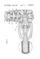
- FIG. 1is a perspective view showing the external configuration and essential components of a SCUBA regulator constructed in accordance with the principles of this invention
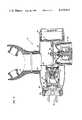
- FIG. 2is a perspective view in quarter section illustrating the first and second stages of the SCUBA regulator shown in FIG. 1, and drawn to an enlarged scale;
- FIG. 3is a section view of the regulator first stage depicted in FIG. 1 and drawn to a precise 2 to 1 scale of an actual embodiment of the invention
- FIG. 4is a section view of the regulator second stage depicted in FIG. 1 and also drawn to a precise 2 to 1 scale of an actual embodiment of the invention
- FIG. 5is a section view of the valve body, main diaphragm valve, control chamber and pilot valve unitary, removable subassembly of the second stage shown in FIG. 4 but drawn to a precise 4 to 1 scale of an actual embodiment of the invention;
- FIG. 6is a section view taken along lines 6--6 of FIG. 5;
- FIGS. 7A, 7B, 7C and 7Dare diagrammatic, section views of the second stage of the regulator as shown in FIG. 4 and illustrating the positioning of interior components of the regulator second stage during a breathing cycle consisting of, in sequence: at rest or stable; initial inhalation causing pilot valve actuation; continued inhalation with both main diaphragm valve and pilot valve actuation; and exhalation, with pilot valve closing and control chamber pressure equalization with source pressure.
- a SCUBA regulatoris depicted including its essential components of a first stage 10, intermediate pressure hose 12 and second stage 14.
- First stage 10includes a machined body 16, made of chrome plated brass, a yoke 18 and yoke screw 20, a dust cap 22, one or more high pressure outlet ports 24, plugged at 26 when not in use, and a plurality of intermediate pressure outlet ports 28, also plugged at 30 when not in use; intermediate pressure hose 12 is threadably connected to one of these ports 28.
- a submersible constant reading pressure gaugewith a suitable length of hose (not shown) is threadably attached to a port 24. The gauge provides the diver with a constant reading of remaining air in his tank.
- first stage 10is attached to a SCUBA tank (not shown) by unthreading yoke screw 20, removing dust cap 22 and placing the high pressure inlet 32 against the outlet seat of the tank (not shown) and threading down yoke screw 20 to hold the tank and first stage in assembly.
- a sintered bronze filter 34is retained in inlet 32 by a retaining ring 36.
- Yoke retainer 38is centrally hosed at 39 to direct high pressure air to an interior high pressure chamber 40 which surrounds the hollow stem 42 of a piston 44.
- Stem 42terminates in knife edge fashion against a high pressure seat 46 made of polytetrafluoroehtylene or other suitable material, located in a threaded seat retainer 48 which is removable for periodic replacement of seat 46.
- valve seat 46opens and intermediate pressure air, typically ambient pressure plus 130 psi plus or minus 10 psi, is then directed through stem 42 and piston 44 to an intermediate pressure port 28 and thus, through intermediate pressure hose 12 to second stage 14.
- the first stage 10is depth compensated due to the exposure of the rear side of piston 44 to ambient pressure.
- the first stageis a balanced valve assembly as high pressure within chamber 40 surrounds stem 42 and thus has no effect at all on the opening and closing of valve seat 46. Accordingly, effort required to move piston 44 is unaffected by tank pressure, which will vary from 4000 psi or less down to a few hundred psi as the air supply is depleted.
- a cap 58houses piston 44 and is threadably attached to body 14 as shown for access to interior parts for the purpose of periodic servicing.
- Various unnumbered elastomer O-ringsare illustrated which serve their usual sealing function and are periodically replaced.
- the upper end 60 of body 10 containing ports 28is swivel mounted as illustrated in FIG. 3 so that the intermediate pressure hose may be positioned as desired by the diver-user.
- Second stage 14includes a generally cylindrically configured casing 62, also made of chrome plated brass.
- a main diaphragm valve and pilot valve subassembly 64(illustrated above in FIG. 5) having an inlet passage 66 is mounted at an inlet 68 end of casing 62 and an exhaust cap 70 with a one way flapper valve 72 therein is mounted in an opposed, open end of casing 62.
- An inhalation control diaphragm assembly 74is also located in the main body of casing 62, generally opposite an outlet passage 76 for the diver-user, having a mouthpiece 78 thereon.
- Casing 62is essentially bisected by a baffle 80 which divides casing 62 into two interior sections, one containing subassembly 64 and the other containing exhaust cap 70 and diaphragm assembly.
- air directed into the casing from subassembly 64will, in the main, pass directly to the diver-user through mouthpiece 78.
- This configurationnot only eliminates potential instabilities as a result of back pressure pulses within casing 62 but also creates an aspirator or venturi effect in the right hand section (FIG. 4) of casing 62 to thus reduce inhalation effort as diver-user demand increases.
- Inhalation control diaphragm assembly 74includes a diaphragm 82 which flexes inwardly when a pressure drop occurs within casing 62 in response to user demand.
- a pilot valve lever control guide 84extends centrally inwardly from diaphragm 82 and is cross bored to receive a pilot valve control lever 86 extended from pilot valve 88 of subassembly 64.
- a spring loaded purge button 90is mounted within diaphragm assembly 74 so that the diver may merely press button 90 to vent air into casing 62.
- Unitary subassembly 64is mounted within casing 62 at casing inlet 68 by a threaded collar 92 and is thus easily removed for servicing or replacement.
- subassembly 62includes a control chamber 94 segregated from inlet passage 66 by a main diaphragm valve 96 at one end and closed at the other end by pilot valve assembly 88.
- Diaphragm valve 96is an elastomer diaphragm with a vulcanized stainless steel bleed orifice 98 located centrally therein to communicate air from passage 66 to control chamber 94.
- Valve 96is tightly clamped about its periphery to one end of control chamber 94 by a clamping plate 100 having a raised circumferential edge 102 and by a raised circumferential edge 104 formed in a peripheral section 106 in the one end of control chamber 94.
- Plate 100further includes a bore 108 formed centrally therein, aligned with orifice 98, and a raised edge 110 which limits center travel of diaphragm valve 96. This structure limits diaphragm valve 96 so as not to exceed its elastic limit and further assures prompt shut off upon return of diaphragm valve 96 to a stable, non-flow position. Plate 100 further includes a second, off center bore 112 to prevent a seal occurring between orifice 98 and bore 108 which would result in free flow to casing 62.
- valve seat 114 for diaphragm valve 96will be explained in detail.
- the seatis formed on section 106 between edge 104 and a 45° counter bore 116 in passage 96 and comprises three concentric sets or rings 118, 120 and 122 of 5 bores, 10 bores and 15 bores progressing outwardly as shown. Additionally, seat 115 is tapered upwardly from outside towards the center of diaphragm valve 96 at an angle of about 3°. This structure permits a progressively larger but controlled flow as demand increases in that as diaphragm valve 96 moves off of seat 114, a larger number of holes are thus exposed to effect greater flow to casing 62 and thus outlet 76.
- Pilot valve assembly 88includes a body member 124 forming a chamber 126 therein and surrounded, interiorally of chamber 94, with a pressure relief spring 128 held by a retainer 130.
- Body member 124is headed at 132 and sealed to chamber 94 by O-ring 134.
- Member 124is axially slidable against pressure exerted by spring 128, in the event of an overpressure condition within chamber 94 so as to break the seal of O-ring 134 and permit air to free flow into casing 62.
- the springis loaded to relieve at 150% of a predetermined control chamber pressure.
- the pilot valveitself is an upstream tilt valve and includes a knife edge opening 136 against a seat 138.
- a pilot seat retainer 140is spring compressed to a stable pilot valve closed condition by spiral spring 142.
- An elastomer seal ring 144is located about lever 86 and serves to direct air flowing from open pilot valve port 144 back towards the left side of casing 62 (FIG. 4) by forming a seal against the baffle 80. This further enhances the venturi flow effect discussed above. Additionally, seal ring 144 is made soft enough so as not to substantially increase inhalation effort by adding significant resistance to control lever 86 travel.
- FIGS. 7A through 7Dthe relationship and movement of parts during a breathing cycle will be set forth.
- FIG. 7Adepicts all parts at rest, valves closed and thus no flow occuring.
- FIG. 7Billustrates the initiation of an inhalation by the diver-user through outlet passage 76.
- Inhalation diaphragm 82is flexed inwardly thus moving control lever 86 and opening pilot valve 88. Air thus flows from control chamber 94 into casing 62 thereby initiating a reduced pressure condition within chamber 94.
- main diaphragm valve 96is caused to flex inwardly and open, as illustrated in exaggerated fashion in FIG. 76. Air is deflected by seal ring 144 and baffle 80 substantially directly into outlet passage 76 to enhance the venturi or aspirating feature of the regulator as discussed above.
- diaphragm 82is flexed outwardly to close pilot valve 88 and the diver's exhalation bubbles out of one way flapper valve 72 into the water.
- pilot valve 88With the closing of pilot valve 88, control chamber 94 equalizes with the pressure from inlet passage 66 through orifice 98 of main diaphragm valve 96, which then closes under assist from its own elastic memory.
- the inhalation effortdoes not exceed 3.5 cm of H 2 O down to 200 feet at a normal breathing rate of 15 breaths per minute, tidal volume of 3 liters.
- the second stage 14will produce 30 cubic feet per minute (cfm), at 1200 psi, 26 to 27 cfm, and at 300 psi, 20 cfm.
- 10-12 cfmwould be an extraordinary high demand by the diver-user.
- the regulatorhas a maximum output of 90 liters per minute which is extraordinarily high and thus above any demand that could be created.
Landscapes
- Health & Medical Sciences (AREA)
- General Health & Medical Sciences (AREA)
- Pulmonology (AREA)
- Engineering & Computer Science (AREA)
- Mechanical Engineering (AREA)
- Ocean & Marine Engineering (AREA)
- Respiratory Apparatuses And Protective Means (AREA)
- Control Of Fluid Pressure (AREA)
Abstract
Description
Claims (19)
Priority Applications (2)
| Application Number | Priority Date | Filing Date | Title |
|---|---|---|---|
| US05/959,242US4219017A (en) | 1978-11-09 | 1978-11-09 | Pilot regulator |
| CA000338518ACA1148441A (en) | 1978-11-09 | 1979-10-26 | Pilot regulator |
Applications Claiming Priority (1)
| Application Number | Priority Date | Filing Date | Title |
|---|---|---|---|
| US05/959,242US4219017A (en) | 1978-11-09 | 1978-11-09 | Pilot regulator |
Publications (1)
| Publication Number | Publication Date |
|---|---|
| US4219017Atrue US4219017A (en) | 1980-08-26 |
Family
ID=25501824
Family Applications (1)
| Application Number | Title | Priority Date | Filing Date |
|---|---|---|---|
| US05/959,242Expired - LifetimeUS4219017A (en) | 1978-11-09 | 1978-11-09 | Pilot regulator |
Country Status (2)
| Country | Link |
|---|---|
| US (1) | US4219017A (en) |
| CA (1) | CA1148441A (en) |
Cited By (43)
| Publication number | Priority date | Publication date | Assignee | Title |
|---|---|---|---|---|
| US4334532A (en)* | 1979-06-21 | 1982-06-15 | Chubb Panorama Limited | Valves and breathing apparatus incorporating such valves |
| USRE31785E (en)* | 1978-08-07 | 1985-01-01 | Figgie International, Inc. | Breathing valve assembly with diaphragm control of the exhaust ports |
| US4494537A (en)* | 1982-06-08 | 1985-01-22 | Gottlieb Mark P | Breathing apparatus for supplying fluid to a user on demand |
| USD283740S (en) | 1983-03-21 | 1986-05-06 | U.S.D. Corp | First stage diving regulator |
| US4625759A (en)* | 1982-11-19 | 1986-12-02 | Alan R. Krasberg | Gas reclaim back pressure regulator |
| US4889115A (en)* | 1986-10-30 | 1989-12-26 | Bozano Enrico D | Air regulator for breathing apparatus |
| EP0389348A1 (en)* | 1989-03-21 | 1990-09-26 | La Spirotechnique Industrielle Et Commerciale | Device for supplying breathing gas to a diver |
| US4971108A (en)* | 1986-09-19 | 1990-11-20 | Mark Gottlieb | Inhalation responsive gas pressure regulator |
| EP0375939A3 (en)* | 1988-12-29 | 1991-06-26 | HTM SPORT S.p.A. | Automatic regulator for breathing apparatus |
| US5038774A (en)* | 1989-05-18 | 1991-08-13 | La Spirotechnique Industrielle Et Commerciale | Process and expander for supplying respiratory gas to an underwater diver |
| US5042525A (en)* | 1990-06-26 | 1991-08-27 | Clark Raymond S | Regulator hanger |
| USD323547S (en) | 1987-07-31 | 1992-01-28 | Karl Widenmann | Ornamental design for a pilot-controlled pressure-limiting valve |
| US5092325A (en)* | 1987-01-20 | 1992-03-03 | Ainscough Kenneth S | Scuba breathing apparatus |
| US5184609A (en)* | 1991-09-03 | 1993-02-09 | U.S. Divers Co., Inc. | Divers first stage adjustable regulator |
| US5411053A (en)* | 1994-07-01 | 1995-05-02 | Daniel A. Holt | Fluid pressure regulator |
| US5471976A (en)* | 1993-06-09 | 1995-12-05 | Smith; Raymond K. | Mini diving system |
| US5540055A (en)* | 1995-01-24 | 1996-07-30 | Kee; Kum | Suction and exhaust connection device |
| WO1996035611A1 (en)* | 1995-05-11 | 1996-11-14 | 'sub-Pratique' | Self-contained breathing apparatus with medium pressure couplings that can be connected and disconnected during diving |
| US5619988A (en)* | 1995-10-05 | 1997-04-15 | Minnesota Mining And Manufacturing Company | First stage pressure regulator for emergency breathing apparatus |
| US5678541A (en)* | 1996-03-15 | 1997-10-21 | Garraffa; Dean R. | Breathing regulator apparatus having automatic flow control |
| EP0838392A1 (en)* | 1996-10-23 | 1998-04-29 | HTM SPORT S.p.A. | Regulator for underwater breathing apparatus |
| EP0937640A1 (en)* | 1998-02-20 | 1999-08-25 | HTM SPORT S.p.A. | Regulator with bypass tube |
| US5979496A (en)* | 1998-01-02 | 1999-11-09 | Daniel A. Holt | Adaptor for engaging a gas pressure source to a gas port |
| US6474325B2 (en) | 1999-01-22 | 2002-11-05 | Npf Limited | Gas regulator |
| EP1182131A3 (en)* | 2000-08-18 | 2002-12-11 | HTM SPORT S.p.A. | Distributor for underwater breathing apparatus |
| US20030000529A1 (en)* | 2001-05-29 | 2003-01-02 | Kay Francis Xavier | Pressure regulator |
| US20040079419A1 (en)* | 2002-07-05 | 2004-04-29 | Taylor Shane S. | Gas valve |
| US20040182446A1 (en)* | 2003-02-04 | 2004-09-23 | Scubapro Europe Srl | Membrane valve and second stage pressure reducer for two-stage underwater regulators incorporating said valve |
| US20040194829A1 (en)* | 2002-09-19 | 2004-10-07 | Zaiser Lenoir E. | Differential pressure valve employing near-balanced pressure |
| US20050095031A1 (en)* | 2003-10-31 | 2005-05-05 | Canon Kabushiki Kaisha | Seal member, developing apparatus, process cartridge and image forming apparatus |
| US20050188975A1 (en)* | 1999-01-22 | 2005-09-01 | Npf Limited | Paintball guns |
| US20050189019A1 (en)* | 2004-02-26 | 2005-09-01 | Johnson Outdoors Inc. | Second exhaust valve for a second stage regulator |
| US20070084469A1 (en)* | 2005-10-11 | 2007-04-19 | Mcdonald Thomas K | Breathing mask and regulator for aircraft |
| WO2008012509A1 (en)* | 2006-07-22 | 2008-01-31 | Cambridge Dive Systems Limited | Pressure activated device and breathing system |
| US20080041384A1 (en)* | 2006-08-16 | 2008-02-21 | La Spirotechnique | Regulating device for supplying breathable gas to a driver |
| US7347206B2 (en)* | 2003-07-25 | 2008-03-25 | Cressi Sub S.P.A. | Control group of a second-stage regulator for scuba divers |
| US8443806B2 (en) | 2005-04-29 | 2013-05-21 | Honeywell International Inc. | Face piece seal check device |
| WO2015160253A1 (en) | 2014-04-16 | 2015-10-22 | Ihc Holland Ie B.V. | On-shore pressure helmet |
| EP3312494A1 (en)* | 2016-09-29 | 2018-04-25 | Linde AG | A regulator assembly for a pressurised gas cylinder |
| US20180200545A1 (en)* | 2015-07-15 | 2018-07-19 | MSA (Suzhou) Safety Equipment R&D Co., Ltd. | Pressure Regulator Assembly and Bypass Assembly for a Self-Contained Breathing Apparatus |
| US20180319472A1 (en)* | 2017-05-04 | 2018-11-08 | Mares S.P.A. | Regulator first stage for two-stage underwater breathing apparatuses |
| US10342705B1 (en)* | 2013-06-13 | 2019-07-09 | Oceanit Laboratories, Inc. | Noise reduction methods and apparatuses for breathing apparatuses and helmets |
| US11613334B2 (en)* | 2017-08-31 | 2023-03-28 | Xdeep Spolka Z Ograniczona Odpowiedzialnoscia | First-stage diving regulator |
Citations (7)
| Publication number | Priority date | Publication date | Assignee | Title |
|---|---|---|---|---|
| US2886049A (en)* | 1956-08-01 | 1959-05-12 | Old Dominion Res And Dev Corp | Amplifying demand valve |
| DE1083658B (en)* | 1953-12-19 | 1960-06-15 | Auergesellschaft Ag | Oxygen breathing apparatus with breathing air circulation and lung-controlled oxygen supply |
| US3250292A (en)* | 1964-03-18 | 1966-05-10 | Ametek Inc | Gauge |
| US3285261A (en)* | 1962-12-21 | 1966-11-15 | Robertshaw Controls Co | Breathing demand regulator |
| US3783891A (en)* | 1972-03-22 | 1974-01-08 | Under Sea Industries | Balanced regulator second stage |
| US3991785A (en)* | 1975-04-28 | 1976-11-16 | Sherwood-Selpac Corporation | Flow regulator valve |
| US4015630A (en)* | 1975-10-23 | 1977-04-05 | Pittman Products, Inc. | Regulator first stage for underwater diving |
- 1978
- 1978-11-09USUS05/959,242patent/US4219017A/ennot_activeExpired - Lifetime
- 1979
- 1979-10-26CACA000338518Apatent/CA1148441A/ennot_activeExpired
Patent Citations (7)
| Publication number | Priority date | Publication date | Assignee | Title |
|---|---|---|---|---|
| DE1083658B (en)* | 1953-12-19 | 1960-06-15 | Auergesellschaft Ag | Oxygen breathing apparatus with breathing air circulation and lung-controlled oxygen supply |
| US2886049A (en)* | 1956-08-01 | 1959-05-12 | Old Dominion Res And Dev Corp | Amplifying demand valve |
| US3285261A (en)* | 1962-12-21 | 1966-11-15 | Robertshaw Controls Co | Breathing demand regulator |
| US3250292A (en)* | 1964-03-18 | 1966-05-10 | Ametek Inc | Gauge |
| US3783891A (en)* | 1972-03-22 | 1974-01-08 | Under Sea Industries | Balanced regulator second stage |
| US3991785A (en)* | 1975-04-28 | 1976-11-16 | Sherwood-Selpac Corporation | Flow regulator valve |
| US4015630A (en)* | 1975-10-23 | 1977-04-05 | Pittman Products, Inc. | Regulator first stage for underwater diving |
Cited By (65)
| Publication number | Priority date | Publication date | Assignee | Title |
|---|---|---|---|---|
| USRE31785E (en)* | 1978-08-07 | 1985-01-01 | Figgie International, Inc. | Breathing valve assembly with diaphragm control of the exhaust ports |
| US4334532A (en)* | 1979-06-21 | 1982-06-15 | Chubb Panorama Limited | Valves and breathing apparatus incorporating such valves |
| US4494537A (en)* | 1982-06-08 | 1985-01-22 | Gottlieb Mark P | Breathing apparatus for supplying fluid to a user on demand |
| US4625759A (en)* | 1982-11-19 | 1986-12-02 | Alan R. Krasberg | Gas reclaim back pressure regulator |
| USD283740S (en) | 1983-03-21 | 1986-05-06 | U.S.D. Corp | First stage diving regulator |
| US4971108A (en)* | 1986-09-19 | 1990-11-20 | Mark Gottlieb | Inhalation responsive gas pressure regulator |
| US4889115A (en)* | 1986-10-30 | 1989-12-26 | Bozano Enrico D | Air regulator for breathing apparatus |
| US5092325A (en)* | 1987-01-20 | 1992-03-03 | Ainscough Kenneth S | Scuba breathing apparatus |
| USD323547S (en) | 1987-07-31 | 1992-01-28 | Karl Widenmann | Ornamental design for a pilot-controlled pressure-limiting valve |
| EP0375939A3 (en)* | 1988-12-29 | 1991-06-26 | HTM SPORT S.p.A. | Automatic regulator for breathing apparatus |
| EP0389348A1 (en)* | 1989-03-21 | 1990-09-26 | La Spirotechnique Industrielle Et Commerciale | Device for supplying breathing gas to a diver |
| FR2644750A1 (en)* | 1989-03-21 | 1990-09-28 | Spirotech Ind Commerc | DEVICE FOR SUPPLYING RESPIRATORY GAS FOR A PLUNGER |
| US5052383A (en)* | 1989-03-21 | 1991-10-01 | La Spirotechnique Industrielle Et Commerciale | Device for supplying breathing gas to a diver |
| US5038774A (en)* | 1989-05-18 | 1991-08-13 | La Spirotechnique Industrielle Et Commerciale | Process and expander for supplying respiratory gas to an underwater diver |
| US5042525A (en)* | 1990-06-26 | 1991-08-27 | Clark Raymond S | Regulator hanger |
| US5184609A (en)* | 1991-09-03 | 1993-02-09 | U.S. Divers Co., Inc. | Divers first stage adjustable regulator |
| US5471976A (en)* | 1993-06-09 | 1995-12-05 | Smith; Raymond K. | Mini diving system |
| US5411053A (en)* | 1994-07-01 | 1995-05-02 | Daniel A. Holt | Fluid pressure regulator |
| US5540055A (en)* | 1995-01-24 | 1996-07-30 | Kee; Kum | Suction and exhaust connection device |
| WO1996035611A1 (en)* | 1995-05-11 | 1996-11-14 | 'sub-Pratique' | Self-contained breathing apparatus with medium pressure couplings that can be connected and disconnected during diving |
| FR2733960A1 (en)* | 1995-05-11 | 1996-11-15 | Sub Pratique | SELF-CONTAINED DIVE BREATHING APPARATUS WITH MIDDLE PRESSURE CONNECTIONS WHICH CAN BE CONNECTED AND DISCONNECTED IN DIVING, AND METHOD OF USING THE SAME |
| US5619988A (en)* | 1995-10-05 | 1997-04-15 | Minnesota Mining And Manufacturing Company | First stage pressure regulator for emergency breathing apparatus |
| US5678541A (en)* | 1996-03-15 | 1997-10-21 | Garraffa; Dean R. | Breathing regulator apparatus having automatic flow control |
| US6021778A (en)* | 1996-10-23 | 2000-02-08 | Htm Sport S.P.A. | Regulator for underwater breathing apparatus |
| EP0838392A1 (en)* | 1996-10-23 | 1998-04-29 | HTM SPORT S.p.A. | Regulator for underwater breathing apparatus |
| US5979496A (en)* | 1998-01-02 | 1999-11-09 | Daniel A. Holt | Adaptor for engaging a gas pressure source to a gas port |
| EP0937640A1 (en)* | 1998-02-20 | 1999-08-25 | HTM SPORT S.p.A. | Regulator with bypass tube |
| US6279575B1 (en) | 1998-02-20 | 2001-08-28 | Htm Sport S.P.A. | Regulator with bypass tube |
| US6474325B2 (en) | 1999-01-22 | 2002-11-05 | Npf Limited | Gas regulator |
| US20050188975A1 (en)* | 1999-01-22 | 2005-09-01 | Npf Limited | Paintball guns |
| EP1182131A3 (en)* | 2000-08-18 | 2002-12-11 | HTM SPORT S.p.A. | Distributor for underwater breathing apparatus |
| US20030000529A1 (en)* | 2001-05-29 | 2003-01-02 | Kay Francis Xavier | Pressure regulator |
| US6729331B2 (en)* | 2001-05-29 | 2004-05-04 | Francis Xavier Kay | Pressure regulator |
| US20040079419A1 (en)* | 2002-07-05 | 2004-04-29 | Taylor Shane S. | Gas valve |
| US7921872B2 (en)* | 2002-07-05 | 2011-04-12 | Taylor Shane S | Gas valve |
| US20040194829A1 (en)* | 2002-09-19 | 2004-10-07 | Zaiser Lenoir E. | Differential pressure valve employing near-balanced pressure |
| US20040182446A1 (en)* | 2003-02-04 | 2004-09-23 | Scubapro Europe Srl | Membrane valve and second stage pressure reducer for two-stage underwater regulators incorporating said valve |
| US7252110B2 (en)* | 2003-02-04 | 2007-08-07 | Scubapro Europe Srl | Membrane valve and second stage pressure reducer for two-stage underwater regulators incorporating said valve |
| EP2068054A3 (en)* | 2003-02-04 | 2012-11-28 | SCUBAPRO EUROPE S.r.l. | Membrane valve and second pressure reducing stage for two-stage regulators for underwater use provided with said valve |
| US7347206B2 (en)* | 2003-07-25 | 2008-03-25 | Cressi Sub S.P.A. | Control group of a second-stage regulator for scuba divers |
| US20050095031A1 (en)* | 2003-10-31 | 2005-05-05 | Canon Kabushiki Kaisha | Seal member, developing apparatus, process cartridge and image forming apparatus |
| US20050189019A1 (en)* | 2004-02-26 | 2005-09-01 | Johnson Outdoors Inc. | Second exhaust valve for a second stage regulator |
| US8443806B2 (en) | 2005-04-29 | 2013-05-21 | Honeywell International Inc. | Face piece seal check device |
| US9616256B2 (en) | 2005-10-11 | 2017-04-11 | B/E Aerospace, Inc. | Breathing mask and regulator for aircraft |
| US20070084469A1 (en)* | 2005-10-11 | 2007-04-19 | Mcdonald Thomas K | Breathing mask and regulator for aircraft |
| US20110061655A1 (en)* | 2005-10-11 | 2011-03-17 | B/E Intellectual Property | Breathing mask and regulator for aircraft |
| US8496005B2 (en) | 2005-10-11 | 2013-07-30 | Be Aerospace, Inc. | Breathing mask and regulator for aircraft |
| US7836886B2 (en)* | 2005-10-11 | 2010-11-23 | B/E Intellectual Property | Breathing mask and regulator for aircraft |
| US20090250062A1 (en)* | 2006-07-22 | 2009-10-08 | Daniel Reynolds | Pressure activated device and breathing system |
| WO2008012509A1 (en)* | 2006-07-22 | 2008-01-31 | Cambridge Dive Systems Limited | Pressure activated device and breathing system |
| US8459263B2 (en) | 2006-07-22 | 2013-06-11 | Cambridge Dive Systems Limited | Pressure activated device and breathing system |
| CN101516722B (en)* | 2006-07-22 | 2013-06-19 | 剑桥潜水系统有限公司 | Pressure activated device and breathing system |
| US20080041384A1 (en)* | 2006-08-16 | 2008-02-21 | La Spirotechnique | Regulating device for supplying breathable gas to a driver |
| US10342705B1 (en)* | 2013-06-13 | 2019-07-09 | Oceanit Laboratories, Inc. | Noise reduction methods and apparatuses for breathing apparatuses and helmets |
| CN106232472A (en)* | 2014-04-16 | 2016-12-14 | Ihc荷兰Ie有限公司 | shore pressure helmet |
| NL2012631A (en)* | 2014-04-16 | 2016-02-02 | Ihc Holland Ie Bv | On-shore pressure helmet. |
| WO2015160253A1 (en) | 2014-04-16 | 2015-10-22 | Ihc Holland Ie B.V. | On-shore pressure helmet |
| US20180200545A1 (en)* | 2015-07-15 | 2018-07-19 | MSA (Suzhou) Safety Equipment R&D Co., Ltd. | Pressure Regulator Assembly and Bypass Assembly for a Self-Contained Breathing Apparatus |
| US11298571B2 (en)* | 2015-07-15 | 2022-04-12 | MSA (Suzhou) Safety Equipment R&D Co., Ltd. | Pressure regulator assembly and bypass assembly for a self-contained breathing apparatus |
| US11497945B2 (en) | 2015-07-15 | 2022-11-15 | MSA (Suzhou) Safety Equipment R&D Co., Ltd. | Pressure regulator assembly and bypass assembly for a self-contained breathing apparatus |
| EP3312494A1 (en)* | 2016-09-29 | 2018-04-25 | Linde AG | A regulator assembly for a pressurised gas cylinder |
| AU2017235903B2 (en)* | 2016-09-29 | 2023-02-02 | Linde Aktiengesellschaft | A regulator assembly for a pressurised gas cylinder |
| US20180319472A1 (en)* | 2017-05-04 | 2018-11-08 | Mares S.P.A. | Regulator first stage for two-stage underwater breathing apparatuses |
| US10569848B2 (en)* | 2017-05-04 | 2020-02-25 | Mares S.P.A. | Regulator first stage for two-stage underwater breathing apparatuses |
| US11613334B2 (en)* | 2017-08-31 | 2023-03-28 | Xdeep Spolka Z Ograniczona Odpowiedzialnoscia | First-stage diving regulator |
Also Published As
| Publication number | Publication date |
|---|---|
| CA1148441A (en) | 1983-06-21 |
Similar Documents
| Publication | Publication Date | Title |
|---|---|---|
| US4219017A (en) | Pilot regulator | |
| US4436090A (en) | Piston actuated, pilot valve operated breathing regulator | |
| US5097860A (en) | Pressure regulator for underwater breathing apparatus | |
| US6729331B2 (en) | Pressure regulator | |
| US5042473A (en) | Demand valve for a respirator | |
| US3783891A (en) | Balanced regulator second stage | |
| US4274404A (en) | Oxygen supply system controlled by user exhalation | |
| US2596178A (en) | Pressure responsive regulator | |
| US5259375A (en) | Second stage scuba regulator with balanced piston volume control | |
| GB2143137A (en) | Combined pressure compensating exhalation and anti-suffocation valve | |
| US4076041A (en) | Pilot valve operated demand regulator for a breathing apparatus | |
| GB2040171A (en) | First stage scuba regulator | |
| US3752175A (en) | Altitude compensating pressure regulator | |
| US4446859A (en) | Breathing apparatus | |
| US3633611A (en) | Single hose underwater regulator | |
| US4037594A (en) | Exhaust regulator valve for push-pull diving system | |
| US5678541A (en) | Breathing regulator apparatus having automatic flow control | |
| US2893386A (en) | Gas demand equipment | |
| US4494537A (en) | Breathing apparatus for supplying fluid to a user on demand | |
| US3329158A (en) | Balanced, single stage-single hose regulator | |
| US3308817A (en) | Reduction regulator valve for scuba system | |
| US4337766A (en) | Valves | |
| US3866622A (en) | Open circuit breathing apparatus | |
| US7171980B2 (en) | Springless regulator valve assembly | |
| EP0019488B1 (en) | Tilt valve and breathing apparatus with which it is used |
Legal Events
| Date | Code | Title | Description |
|---|---|---|---|
| RF | Reissue application filed | Effective date:19830218 | |
| AS | Assignment | Owner name:COMMONWEALTH FINANCIAL CORPORATION Free format text:SECURITY INTEREST;ASSIGNOR:OSTERHOUT, RALPH F.;REEL/FRAME:004559/0267 Effective date:19851108 | |
| AS | Assignment | Owner name:ROYDELL, INC., A CORP. OF CALIFORNIA Free format text:ASSIGNMENT OF ASSIGNORS INTEREST.;ASSIGNOR:S-TRON HOLDINGS, INC., A CORP. OF CALIFORNIA;REEL/FRAME:005622/0125 Effective date:19901228 | |
| AS | Assignment | Owner name:LASHDELL UNDERWATER PARTNERS A CA GENERAL PARTNER Free format text:ASSIGNMENT OF ASSIGNORS INTEREST.;ASSIGNOR:ROYDELL, INC., A CORP. OF CA;REEL/FRAME:005945/0250 Effective date:19910124 | |
| AS | Assignment | Owner name:S-TRON HOLDINGS, INC. Free format text:CHANGE OF NAME;ASSIGNOR:TEKNA, A CORP. OF CA;REEL/FRAME:006085/0097 Effective date:19900413 | |
| AS | Assignment | Owner name:OCEAN REEF, INC. Free format text:ASSIGNMENT OF ASSIGNORS INTEREST;ASSIGNOR:LASHDELL UNDERWATER PARTNERS;REEL/FRAME:006631/0278 Effective date:19930521 |