US4214779A - Coupling device - Google Patents
Coupling deviceDownload PDFInfo
- Publication number
- US4214779A US4214779AUS05/880,774US88077478AUS4214779AUS 4214779 AUS4214779 AUS 4214779AUS 88077478 AUS88077478 AUS 88077478AUS 4214779 AUS4214779 AUS 4214779A
- Authority
- US
- United States
- Prior art keywords
- coupling
- axial
- fluid
- opening
- coupling member
- Prior art date
- Legal status (The legal status is an assumption and is not a legal conclusion. Google has not performed a legal analysis and makes no representation as to the accuracy of the status listed.)
- Expired - Lifetime
Links
Images

Classifications
- A—HUMAN NECESSITIES
- A61—MEDICAL OR VETERINARY SCIENCE; HYGIENE
- A61M—DEVICES FOR INTRODUCING MEDIA INTO, OR ONTO, THE BODY; DEVICES FOR TRANSDUCING BODY MEDIA OR FOR TAKING MEDIA FROM THE BODY; DEVICES FOR PRODUCING OR ENDING SLEEP OR STUPOR
- A61M39/00—Tubes, tube connectors, tube couplings, valves, access sites or the like, specially adapted for medical use
- A61M39/02—Access sites
- A61M39/04—Access sites having pierceable self-sealing members
- F—MECHANICAL ENGINEERING; LIGHTING; HEATING; WEAPONS; BLASTING
- F16—ENGINEERING ELEMENTS AND UNITS; GENERAL MEASURES FOR PRODUCING AND MAINTAINING EFFECTIVE FUNCTIONING OF MACHINES OR INSTALLATIONS; THERMAL INSULATION IN GENERAL
- F16L—PIPES; JOINTS OR FITTINGS FOR PIPES; SUPPORTS FOR PIPES, CABLES OR PROTECTIVE TUBING; MEANS FOR THERMAL INSULATION IN GENERAL
- F16L37/00—Couplings of the quick-acting type
- F16L37/08—Couplings of the quick-acting type in which the connection between abutting or axially overlapping ends is maintained by locking members
- F16L37/084—Couplings of the quick-acting type in which the connection between abutting or axially overlapping ends is maintained by locking members combined with automatic locking
- F—MECHANICAL ENGINEERING; LIGHTING; HEATING; WEAPONS; BLASTING
- F16—ENGINEERING ELEMENTS AND UNITS; GENERAL MEASURES FOR PRODUCING AND MAINTAINING EFFECTIVE FUNCTIONING OF MACHINES OR INSTALLATIONS; THERMAL INSULATION IN GENERAL
- F16L—PIPES; JOINTS OR FITTINGS FOR PIPES; SUPPORTS FOR PIPES, CABLES OR PROTECTIVE TUBING; MEANS FOR THERMAL INSULATION IN GENERAL
- F16L55/00—Devices or appurtenances for use in, or in connection with, pipes or pipe systems
- Y—GENERAL TAGGING OF NEW TECHNOLOGICAL DEVELOPMENTS; GENERAL TAGGING OF CROSS-SECTIONAL TECHNOLOGIES SPANNING OVER SEVERAL SECTIONS OF THE IPC; TECHNICAL SUBJECTS COVERED BY FORMER USPC CROSS-REFERENCE ART COLLECTIONS [XRACs] AND DIGESTS
- Y10—TECHNICAL SUBJECTS COVERED BY FORMER USPC
- Y10S—TECHNICAL SUBJECTS COVERED BY FORMER USPC CROSS-REFERENCE ART COLLECTIONS [XRACs] AND DIGESTS
- Y10S285/00—Pipe joints or couplings
- Y10S285/921—Snap-fit
Definitions
- the present inventionrelates to coupling devices for joining together two fluid conduits and more particularly to such coupling devices which also provide access to the fluid in the fluid conduits.
- fluidmeans gases as well as liquids.
- Coupling devices for joining together of two fluid conduitsare well known. Such devices are useful for a wide variety of purposes in which it is desirable to connect one conduit to another conduit to allow fluid to flow from one conduit into and through the other conduit. In most instances it also is desirable to make this connection so that there is no leakage or spillage at the junction of the two conduits.
- the coupling deviceserves not only to provide a fluid passage therethrough but to also provide a means for sealing such fluid passage.
- Such devicesare particularly useful in joining together the fluid conduits for blood and dialysis liquid in dialysis systems where it is most important that there be no leakage between the connections.
- the present inventionprovides a coupling device for joining together two fluid conduits while at the same time providing for fluid access to the fluid passing through the fluid conduits.
- the coupling devicecomprises a first coupling member which is adapted to be connected to one of the fluid conduits and a second coupling member adapted to be connected to the other fluid conduit.
- the first and second coupling membersin turn are adapted to be connected so as to define an axial fluid passage therethrough between the two fluid conduits.
- An elastic member having an axial fluid opening therethroughis interposed between the first and second coupling members and has its axial opening axially aligned with the axial fluid passage defined by such first and second coupling members.
- Connecting meansare provided for connecting the first and second coupling members together to axially compress the elastic member between the first and second coupling members in order to seal the fluid passage.
- At least one of the first and second coupling membersincludes an opening therethrough adjacent to the wall of the elastic member whereby selective fluid communication with the fluid in the fluid conduit can be obtained through the wall of the elastic member.
- the coupling device of the present inventionprovides a simple reliable device which allows for the injection and/or withdrawal of samples through an elastic wall with the help of cannulas or the like without the risk of leakage.
- the elastic memberis a tubular elastic member which is adapted to be compressed between axial end faces of the mating ends of the first and second coupling members. Additionally, either or both of the mating ends may be provided with an annular groove for guiding of the respective ends of the tubular elastic member.
- either or both of the mating ends of the first and second coupling membersare provided with conically projecting parts which are adapted to mate with complementary surfaces of the elastic tubular member so that the conically projecting parts of the mating ends are tightly pressed inwardly into the axial fluid opening through the elastic tubular member when the first and second coupling members are connected together by the connecting means.
- the connecting meanscomprises a circumferential groove on the surface of the first coupling member and hook means on the second coupling member which is adapted to engage the circumferential groove so that the elastic member is axially compressed between the first and second coupling members.
- the one coupling member having the opening therethrough adjacent the wall of the elastic memberis provided with a rigid wall of relatively hard material on the opposite side of the axial fluid passage from the opening in order to prevent accidential penetration through such wall by means of the cannula used to inject and/or withdraw samples.
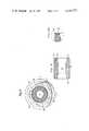
- FIG. 1is a sectional view of the coupling device according to the present invention.
- FIG. 2is a cross-sectional view taken along lines A--A of FIG. 1;
- FIG. 3is an enlarged sectional view of the elastic member of the coupling device of the present invention in its disassembled unclamped position
- FIG. 3Ais a still further enlarged sectional view of the portion of the elastic member within the circle portion of FIG. 3.
- the coupling device of the present inventionis mainly intended for being connected into conduits for blood and dialysis liquid in dialysis systems, the present invention will be described in such content.
- the devicemay also be used in other instances, for example in connection with oxygenerators and in fact, it can be used for coupling or joining together any two fluid conduits.
- the term fluidis intended here to mean gases as well as liquids.
- FIG. 1there is shown a longitudinal sectional view of the coupling device according to the present invention in which two axially mating coupling members 1 and 2 are shown connected to flexible tubes or other types of fluid conduits 3 and 4.
- two axially mating coupling members 1 and 2are shown connected to flexible tubes or other types of fluid conduits 3 and 4.
- the construction in such a casewill be substantially the same as if two flexible tubes are being joined together.
- the axially mating component 1is provided with a circumferential groove 5 which is engaged by hooks 6 and 7 on the axially mating component or member 2.
- the hooks 6 and 7are arranged about the outside diameter of an annular groove formed in the end of component 2. It is into this annular groove that the portion of component 1 having the circumferential groove 5 therein is inserted so that the hooks 6 and 7 may snap into the groove 5.
- these hooks 6 and 7are arranged straight in front of through-hooks 8. This makes it possible for the component 2 to be manufactured by means of a simple two-part molding tool, as is well known in the art. In FIG. 1, only two hooks 6 and 7 are shown. However, in practice, preferably three or more such hooks are used. Of the two hooks shown, only the hook 7 is sectioned in order to indicate that only this hook is located in the sectional plane.
- the hook 6on the other hand is peripherally displaced to a greater or lesser extent in relation to this section.
- FIGS. 3 and 3Athere is shown an elastic insert element 9 which is adapted to be clamped between the two axially mating components 1 and 2 to seal the fluid passage through the coupling device.
- the axial end faces 10 and 11 of the element 9are pressed tightly against the corresponding axial end faces 12 and 13 of the two components or members 1 and 2. In this way, leakage is prevented across the end faces 10, 12, and 11, 13 which are mated together.
- the elastic insert 9is provided on its end faces 10, 11 with concentrically arranged sealing beads 14 which further serve to improve the seal when the elastic member 9 is clamped between the axial end faces 12 and 13.
- corresponding sealing beadscan be arranged on the surfaces 12 and 13 of the two axially mating components 1, 2 and against which the axial end faces 10 and 11 of the tubular elastic element 9 rest.
- FIG. 2shows a section taken along lines A--A of FIG. 1.
- FIG. 2also indicates that the coupling member 1 is provided with two openings 15 and 16 which are intended for injection and/or taking of samples, which may be done by means of cannulas, through the wall of the elastic tubular member 9.
- the coupling member 1is provided with a thicker wall section 17 straight in front of the openings 15 and 16. This wall 17, like the rest of the coupling component 1, is manufactured of a relatively rigid hard material.
- Such relatively hard material straight in front of the openingsfurther insures that the wall section 17 will not accidentially be penetrated by means of the cannula.
- This protection against penetrationis desirable since such penetration could be very dangerous to the person performing the sample taking owing to the risk of infection with, for example, hepatitis.
- the opening for providing access to the fluid through the wall of the elastic member 9is situated in the region of the second coupling member 2, such coupling member 2 could also be provided with a thick rigid wall opposite such opening intended for injection and/or sample taking.
- the coupling member or component 1 having the opening or openings for injection and/or sample takingis of a substantially triangular cross-section having three walls joined together.
- the outer surface of one of the walls 17is located further away from the center of the flow opening through the coupling component 1 than the other outer surfaces of the other two walls which are each provided with the opening or openings 15, 16. In this way, the section of the outer walls directly opposite from the openings are relatively thick so as to prevent accidential penetration by a cannula.
- the coupling members or components 1 and 2are provided with conically projecting parts 19 and 20 which are matched to complementary surfaces of the tubular elastic member 9.
- the conically projecting parts 19 and 20are adapted so that on snapping together of the two coupling members 1 and 2, the conically projecting parts 19 and 20 are tightly pressed into the axial hole 21 in the tubular elastic member 9 for further improvement of the seal. That is, the side walls of the elastic tubular member 9 engaging the conical parts 19 and 20 serve as a further seal in addition to the seal provided by mating of the axial end faces of the tubular elastic member 9 with the corresponding end surfaces of the coupling members 1 and 2.
- annular groove 22Between the outer wall of the component 1 and the conically projecting part 19 there is provided an annular groove 22, the base of which constitutes the axial end surface 12 of the component 1.
- a corresponding but incompletely formed groove 23is provided in the component or member 2.
- This groove 23has a base 13 and is partly delimited by the conically projecting part 20.
- the present inventionis not limited simply to the above mentioned embodiment, but can be varied within the scope of the following patent claims.
- Different materialsmay be used, for example, for the different parts. It has been found suitable to use latex, silicone rubber, or polyurethane for the tubular elastic member 9. Other materials, however, may be used.
- different thermoplasticssuch as PVC or polyethylene may be used for the coupling components 1 and 2. However, other thermoplastics, and also thermosetting resins, may also be used.
- the different parts of the constructionmay be varied in shape without thereby exceeding the scope of the present invention.
Landscapes
- Engineering & Computer Science (AREA)
- General Engineering & Computer Science (AREA)
- Health & Medical Sciences (AREA)
- Mechanical Engineering (AREA)
- Heart & Thoracic Surgery (AREA)
- Hematology (AREA)
- Anesthesiology (AREA)
- Biomedical Technology (AREA)
- Pulmonology (AREA)
- Life Sciences & Earth Sciences (AREA)
- Animal Behavior & Ethology (AREA)
- General Health & Medical Sciences (AREA)
- Public Health (AREA)
- Veterinary Medicine (AREA)
- Quick-Acting Or Multi-Walled Pipe Joints (AREA)
- Infusion, Injection, And Reservoir Apparatuses (AREA)
- External Artificial Organs (AREA)
Abstract
Description
The present invention relates to coupling devices for joining together two fluid conduits and more particularly to such coupling devices which also provide access to the fluid in the fluid conduits. In the context of the present invention, the term fluid means gases as well as liquids.
Coupling devices for joining together of two fluid conduits are well known. Such devices are useful for a wide variety of purposes in which it is desirable to connect one conduit to another conduit to allow fluid to flow from one conduit into and through the other conduit. In most instances it also is desirable to make this connection so that there is no leakage or spillage at the junction of the two conduits. Thus, the coupling device serves not only to provide a fluid passage therethrough but to also provide a means for sealing such fluid passage. Such devices are particularly useful in joining together the fluid conduits for blood and dialysis liquid in dialysis systems where it is most important that there be no leakage between the connections.
Often times it is also desirable to provide means for taking of samples of the fluid passing in the fluid conduits and/or for injecting material into the fluid. For example, with blood and dialysis liquid conduits for dialysis systems, such samples and/or injections can be made with the help of cannulas or the like. In such cases, it is most desirable to take such samples or inject such materials without causing any leakage of the fluid from the fluid conduit.
The present invention provides a coupling device for joining together two fluid conduits while at the same time providing for fluid access to the fluid passing through the fluid conduits. The coupling device comprises a first coupling member which is adapted to be connected to one of the fluid conduits and a second coupling member adapted to be connected to the other fluid conduit. The first and second coupling members in turn are adapted to be connected so as to define an axial fluid passage therethrough between the two fluid conduits. An elastic member having an axial fluid opening therethrough is interposed between the first and second coupling members and has its axial opening axially aligned with the axial fluid passage defined by such first and second coupling members. Connecting means are provided for connecting the first and second coupling members together to axially compress the elastic member between the first and second coupling members in order to seal the fluid passage. At least one of the first and second coupling members includes an opening therethrough adjacent to the wall of the elastic member whereby selective fluid communication with the fluid in the fluid conduit can be obtained through the wall of the elastic member.
Accordingly, the coupling device of the present invention provides a simple reliable device which allows for the injection and/or withdrawal of samples through an elastic wall with the help of cannulas or the like without the risk of leakage.
In a preferred embodiment of the present invention, the elastic member is a tubular elastic member which is adapted to be compressed between axial end faces of the mating ends of the first and second coupling members. Additionally, either or both of the mating ends may be provided with an annular groove for guiding of the respective ends of the tubular elastic member.
In another preferred embodiment, either or both of the mating ends of the first and second coupling members are provided with conically projecting parts which are adapted to mate with complementary surfaces of the elastic tubular member so that the conically projecting parts of the mating ends are tightly pressed inwardly into the axial fluid opening through the elastic tubular member when the first and second coupling members are connected together by the connecting means.
In a still further preferred embodiment, the connecting means comprises a circumferential groove on the surface of the first coupling member and hook means on the second coupling member which is adapted to engage the circumferential groove so that the elastic member is axially compressed between the first and second coupling members.
In another embodiment of the present invention, the one coupling member having the opening therethrough adjacent the wall of the elastic member is provided with a rigid wall of relatively hard material on the opposite side of the axial fluid passage from the opening in order to prevent accidential penetration through such wall by means of the cannula used to inject and/or withdraw samples.
These and further features and characteristics of the present invention will be apparent from the following detailed description in which reference is made to the enclosed drawings which illustrate a preferred embodiment of the present invention.
FIG. 1 is a sectional view of the coupling device according to the present invention;
FIG. 2 is a cross-sectional view taken along lines A--A of FIG. 1;
FIG. 3 is an enlarged sectional view of the elastic member of the coupling device of the present invention in its disassembled unclamped position; and
FIG. 3A is a still further enlarged sectional view of the portion of the elastic member within the circle portion of FIG. 3.
As the coupling device of the present invention is mainly intended for being connected into conduits for blood and dialysis liquid in dialysis systems, the present invention will be described in such content. However, it should be realized that the device may also be used in other instances, for example in connection with oxygenerators and in fact, it can be used for coupling or joining together any two fluid conduits. In this regard, it should be noted that the term fluid is intended here to mean gases as well as liquids.
Turning first to FIG. 1, there is shown a longitudinal sectional view of the coupling device according to the present invention in which two axially mating coupling members 1 and 2 are shown connected to flexible tubes or other types of fluid conduits 3 and 4. In principle, however, there is nothing to prevent either of the components or members 1 and 2 from constituting a part of a housing to which a flexible tube may be connected. The construction in such a case will be substantially the same as if two flexible tubes are being joined together.
The axially mating component 1 is provided with a circumferential groove 5 which is engaged byhooks 6 and 7 on the axially mating component or member 2. Thehooks 6 and 7 are arranged about the outside diameter of an annular groove formed in the end of component 2. It is into this annular groove that the portion of component 1 having the circumferential groove 5 therein is inserted so that thehooks 6 and 7 may snap into the groove 5. For reasons of manufacturing technique, thesehooks 6 and 7 are arranged straight in front of through-hooks 8. This makes it possible for the component 2 to be manufactured by means of a simple two-part molding tool, as is well known in the art. In FIG. 1, only twohooks 6 and 7 are shown. However, in practice, preferably three or more such hooks are used. Of the two hooks shown, only the hook 7 is sectioned in order to indicate that only this hook is located in the sectional plane. Thehook 6 on the other hand is peripherally displaced to a greater or lesser extent in relation to this section.
In FIGS. 3 and 3A, there is shown an elastic insert element 9 which is adapted to be clamped between the two axially mating components 1 and 2 to seal the fluid passage through the coupling device. In its clamped state, shown in FIG. 1, the axial end faces 10 and 11 of the element 9 are pressed tightly against the correspondingaxial end faces end faces 10, 11 with concentrically arranged sealingbeads 14 which further serve to improve the seal when the elastic member 9 is clamped between theaxial end faces surfaces
The cross-section of the coupling component or member 1 is best seen in FIG. 2 which shows a section taken along lines A--A of FIG. 1. FIG. 2 also indicates that the coupling member 1 is provided with twoopenings thicker wall section 17 straight in front of theopenings wall 17, like the rest of the coupling component 1, is manufactured of a relatively rigid hard material. Such relatively hard material straight in front of the openings further insures that thewall section 17 will not accidentially be penetrated by means of the cannula. This protection against penetration is desirable since such penetration could be very dangerous to the person performing the sample taking owing to the risk of infection with, for example, hepatitis. Similarly, if the opening for providing access to the fluid through the wall of the elastic member 9 is situated in the region of the second coupling member 2, such coupling member 2 could also be provided with a thick rigid wall opposite such opening intended for injection and/or sample taking.
For further protection against penetration, the coupling member or component 1 having the opening or openings for injection and/or sample taking is of a substantially triangular cross-section having three walls joined together. The outer surface of one of thewalls 17 is located further away from the center of the flow opening through the coupling component 1 than the other outer surfaces of the other two walls which are each provided with the opening oropenings
It is to be noted that after any injection and/or sample taking, the area of injection will be pressed together automatically by the axial pressure exerted by the two coupling members 1 and 2. Thus, there will be no leakage of fluid out of the opening in the side wall of the elastic member 9. This axial compression of the elastic tubular member 9 is further insured by the fact that the elastic element 9 is arranged with aplay 18 within the coupling component or member 1, thereby insuring that the full axial compression force exerted between the coupling members 1 and 2 will act on the axial end faces 10, 11 of the elastic member 9.
On their axial end faces directed towards one another, the coupling members or components 1 and 2 are provided with conically projectingparts conically projecting parts conically projecting parts axial hole 21 in the tubular elastic member 9 for further improvement of the seal. That is, the side walls of the elastic tubular member 9 engaging theconical parts
Between the outer wall of the component 1 and theconically projecting part 19 there is provided anannular groove 22, the base of which constitutes theaxial end surface 12 of the component 1. A corresponding but incompletely formedgroove 23 is provided in the component or member 2. Thisgroove 23 has abase 13 and is partly delimited by theconically projecting part 20. Thesegrooves
Naturally, the present invention is not limited simply to the above mentioned embodiment, but can be varied within the scope of the following patent claims. Different materials may be used, for example, for the different parts. It has been found suitable to use latex, silicone rubber, or polyurethane for the tubular elastic member 9. Other materials, however, may be used. Similarly, different thermoplastics such as PVC or polyethylene may be used for the coupling components 1 and 2. However, other thermoplastics, and also thermosetting resins, may also be used. For the rest, the different parts of the construction may be varied in shape without thereby exceeding the scope of the present invention.
Claims (13)
1. A coupling device for joining together two fluid conduits and for providing fluid access to the fluid in the fluid conduits, said coupling device comprising:
a first coupling member adapted to be connected to one of said fluid conduits;
a second coupling member adapted to be connected to the other of said fluid conduits, said first and second coupling members being adapted to be connected together to define an axial fluid passage through said first and second coupling members between said two fluid conduits;
an elastic member having an axial fluid opening therethrough interposed between said first and second coupling members, said axial fluid opening of said elastic member being axially aligned with said axial fluid passage defined by said first and second coupling members;
connecting means for connecting said first and second coupling members together to axially compress said elastic member between said first and second coupling members to seal said axial fluid passage without compressing said elastic member transversely of the axial direction; at least one of said first and second coupling members including an overlapping wall section overlappping said elastic member, and an opening defined in said overlapping wall section to provide access to said elastic member; into engagement with said overlapping wall section and in line with the opening in said overlapping wall section and
at least a portion of the wall of said elastic member in line with the opening in said overlapping wall section, being resealably penetrable to provide selective fluid communication with the fluid in said fluid conduits through said portion of the wall of said elastic member.
2. The coupling device of claim 1 wherein said first and second coupling members each have a mating end having an axial opening therein and having axial end surfaces, said first and second mating ends being axially connectable together by said connecting means with said axial end surfaces being directed toward one another and said axial openings thereof defining said axial fluid passage, and wherein said elastic member is axially compressed between said axial end surfaces.
3. The coupling device of claim 2 wherein said elastic member comprises a tubular elastic element having axial end surfaces adapted to mate with said axial end surfaces of said first and second coupling members.
4. The coupling device of claim 3 wherein said mating end of said first coupling member is provided with an annular groove in the end thereof for guiding one end of said tubular elastic element, said axial end surface of said first coupling member being defined by the bottom of said annular groove in said first coupling member.
5. The coupling device of claim 4 wherein said mating end of said second coupling member is also provided with an annular groove in the end thereof for guiding the other end of said tubular elastic element, said axial end surface of said second coupling member being defined by the bottom of said annular groove in said second coupling member.
6. The coupling device of claim 3 wherein said mating end of said first coupling member is provided with a conically projecting part and wherein a portion of said tubular elastic element is provided with a complementary surface adapted to mate with said conically projecting part whereby when said first and second coupling members are connected together by said connecting means, said conically projecting part is tightly pressed inwardly into said axial fluid opening through said tubular elastic element to further seal said fluid passage.
7. The coupling device of claim 6 wherein said mating end of said second coupling member is also provided with a conically projecting part and wherein a portion of said tubular elastic element is provided with a complementary surface adapted to mate with said conically projecting part whereby when said first and second coupling members are connected together by said connecting means, said conically projecting parts are tightly pressed inwardly into said axial fluid opening through said tubular elastic element to further seal said fluid passage.
8. The coupling device of claim 3 wherein each of said axial end surfaces of said tubular elastic element include at least one annular sealing bead thereon, said annular sealing beads being adapted to engage the axial end surfaces of said coupling members to seal said fluid passage.
9. The coupling device of claim 8 wherein each of said axial end surfaces of said tubular elastic element is provided with two concentrically arranged annular sealing beads.
10. The coupling device of claim 3 wherein said one coupling member having said overlapping wall section and said opening therein has three joined wall sections at the axial location of said opening surrounding said tubular elastic member, the outer surface of one of said wall sections being located a greater distance from the center of said axial opening in the mating end thereof than the outer surfaces of the other two wall sections.
11. The coupling device of claim 1 wherein said one coupling member having said overlapping wall section and said opening therein is further provided with a rigid wall section of relatively hard material on the opposite side of said axial fluid passage from said opening in said one coupling member to prevent access to the fluid in said fluid conduits through said opposite side of said axial fluid passage.
12. The coupling device of claim 1 wherein said connecting means comprises a circumferential groove on the surface of said first coupling member and hook means on said second member adapted to engage portions of said circumferential groove on said first coupling member to lock said first and second coupling member together to axially compress said elastic member between said first and second coupling members.
13. The coupling device of claim 12 wherein said circumferential groove is formed on the outer surface of a portion of said mating end of said first coupling member and wherein said second coupling member is provided with an annular groove in said mating end thereof which is adapted to receive said portion of said mating end of said first coupling member having said circumferential groove, and said hook means is formed in the outer side walls of said annular groove of said second coupling member so that said hook means engages portions of said circumferential groove when said mating end of said first coupling member is inserted into said annular groove of said second coupling member to axially compress said elastic member.
Applications Claiming Priority (2)
| Application Number | Priority Date | Filing Date | Title |
|---|---|---|---|
| SE7702496 | 1977-03-07 | ||
| SE7702496ASE415728B (en) | 1977-03-07 | 1977-03-07 | COUPLING |
Publications (1)
| Publication Number | Publication Date |
|---|---|
| US4214779Atrue US4214779A (en) | 1980-07-29 |
Family
ID=20330633
Family Applications (1)
| Application Number | Title | Priority Date | Filing Date |
|---|---|---|---|
| US05/880,774Expired - LifetimeUS4214779A (en) | 1977-03-07 | 1978-02-24 | Coupling device |
Country Status (8)
| Country | Link |
|---|---|
| US (1) | US4214779A (en) |
| JP (1) | JPS53111696A (en) |
| DE (1) | DE2805416A1 (en) |
| FR (1) | FR2383386A1 (en) |
| GB (1) | GB1582914A (en) |
| IT (1) | IT1108840B (en) |
| NL (1) | NL7802437A (en) |
| SE (1) | SE415728B (en) |
Cited By (65)
| Publication number | Priority date | Publication date | Assignee | Title |
|---|---|---|---|---|
| US4373753A (en)* | 1981-05-18 | 1983-02-15 | Shell Oil Company | Spring finger connector |
| US4398757A (en)* | 1981-02-18 | 1983-08-16 | Floyd Larry K | Laminar flow connector for blood and sterile solutions |
| US4422674A (en)* | 1980-11-03 | 1983-12-27 | Rockwell International Corporation | Tamper proof gas meter |
| US4433973A (en) | 1982-01-12 | 1984-02-28 | Bioresearch Inc. | Reusable tube connector assembly |
| US4519636A (en)* | 1982-10-20 | 1985-05-28 | Koomey, Inc. | Seal for an underwater connector |
| US4542922A (en)* | 1982-02-05 | 1985-09-24 | Agro Ag. | Fitting for connecting circumferentially ribbed insulating tubes of plastic |
| US4679827A (en)* | 1984-12-28 | 1987-07-14 | Thomas & Betts Corporation | Raintight and oiltight connector for flexible conduit |
| US4735440A (en)* | 1985-07-05 | 1988-04-05 | Rasmussen Gmbh | Hose coupling |
| US4786085A (en)* | 1987-01-27 | 1988-11-22 | Rasmussen Gmbh | Coupling device for tubular members |
| US4786089A (en)* | 1986-11-17 | 1988-11-22 | Ford Motor Company | Automatically locking tubing coupler |
| US4824145A (en)* | 1986-06-06 | 1989-04-25 | Gambro Ab | Coupling components |
| US4838855A (en)* | 1987-07-31 | 1989-06-13 | Lynn Lawrence A | Blood aspiration assembly and method |
| US5040729A (en)* | 1990-02-15 | 1991-08-20 | Carrozza Mark J | Sprinkler system |
| US5199947A (en)* | 1983-01-24 | 1993-04-06 | Icu Medical, Inc. | Method of locking an influent line to a piggyback connector |
| US5211426A (en)* | 1989-09-29 | 1993-05-18 | Hutchinson | Point irrigation apparatus with branch connections |
| US5281206A (en)* | 1983-01-24 | 1994-01-25 | Icu Medical, Inc. | Needle connector with rotatable collar |
| US5344414A (en)* | 1983-01-24 | 1994-09-06 | Icu Medical Inc. | Medical connector |
| US5447495A (en)* | 1987-07-31 | 1995-09-05 | Lawrence A. Lynn | Apparatus and methods for transferring blood between a blood aspirator assembly and an external container |
| US5474544A (en)* | 1994-05-25 | 1995-12-12 | Lynn; Lawrence A. | Luer-receiving medical valve |
| US5531672A (en)* | 1987-07-31 | 1996-07-02 | Lawrence A. Lynn | Blood aspiration assembly components and blunt needle aspirators |
| US5549569A (en)* | 1994-02-15 | 1996-08-27 | Lawrence A. Lynn | Ex vivo blood isolation system |
| US5549651A (en)* | 1994-05-25 | 1996-08-27 | Lynn; Lawrence A. | Luer-receiving medical valve and fluid transfer method |
| US5636875A (en)* | 1993-07-16 | 1997-06-10 | Ems-Inventa Ag | Two-part tubular connector made of polymers as well as conduit system incorporating such connector and pipes made of the same polymers |
| US5641184A (en)* | 1992-07-06 | 1997-06-24 | Maersk Medical A/S | Tube, especially for medical use, method of producing said tube, and tool for use in the implementation of the method |
| US5679926A (en)* | 1996-02-22 | 1997-10-21 | General Motors Corporation | Sleeve retainer for sensor |
| US5688254A (en)* | 1983-01-24 | 1997-11-18 | Icu Medical, Inc. | Medical connector |
| US5694686A (en)* | 1991-12-18 | 1997-12-09 | Icu Medical, Inc. | Method for assembling a medical valve |
| USD393722S (en) | 1996-04-04 | 1998-04-21 | Icu Medical, Inc. | Locking blunt cannula |
| US5759160A (en)* | 1995-11-20 | 1998-06-02 | Utah Medical Products, Inc. | Blood sampling system |
| US5810792A (en)* | 1996-04-03 | 1998-09-22 | Icu Medical, Inc. | Locking blunt cannula |
| US6059484A (en)* | 1995-11-17 | 2000-05-09 | Greive; Michael | Guide wire introducer assembly with guide wire grip and release means |
| US20020040207A1 (en)* | 1995-12-15 | 2002-04-04 | Lopez George A. | Medical valve with fluid escape space |
| US6572592B1 (en) | 1991-12-18 | 2003-06-03 | Icu Medical, Inc. | Medical valve and method of use |
| USRE38145E1 (en)* | 1994-05-25 | 2003-06-17 | Lawrence A. Lynn | Luer-receiving medical valve |
| US6599273B1 (en) | 1991-12-18 | 2003-07-29 | Icu Medical, Inc. | Fluid transfer device and method of use |
| US6612536B2 (en)* | 2000-10-04 | 2003-09-02 | Martin Walter Dalton | Remote shut-off valve |
| US6676167B2 (en) | 2002-05-20 | 2004-01-13 | Visteon Global Technologies, Inc. | Air conditioning block fitting with two surface sealing |
| US20040019314A1 (en)* | 2001-03-02 | 2004-01-29 | Annalisa Delnevo | Dialysis machine blood circulating circuit fitting |
| US20040030321A1 (en)* | 2000-07-11 | 2004-02-12 | Fangrow Thomas F. | Medical valve with positive flow characteristics |
| US6834893B2 (en) | 2001-11-01 | 2004-12-28 | Visteon Global Technologies, Inc. | Peanut fittings for CO2 air conditioning systems |
| US20050197646A1 (en)* | 2002-02-11 | 2005-09-08 | Brian Connell | Dialysis connector with retention and feedback features |
| US20060212006A1 (en)* | 1996-12-16 | 2006-09-21 | Fangrow Thomas F Jr | Medical valve with positive flow characteristics |
| US20060211998A1 (en)* | 2004-11-05 | 2006-09-21 | Fangrow Thomas F | Soft-grip medical connector |
| USRE39334E1 (en)* | 1994-05-25 | 2006-10-10 | Lynn Lawrence A | Luer-receiving medical valve and fluid transfer method |
| US20080086087A1 (en)* | 2004-04-16 | 2008-04-10 | Spohn Michael A | Fluid delivery system including a fluid path set with sterile check valve connector |
| US20080214991A1 (en)* | 2007-03-02 | 2008-09-04 | Brett Haarala | Catheter system with attachable catheter hub |
| US7611503B2 (en) | 2004-04-16 | 2009-11-03 | Medrad, Inc. | Fluid delivery system, fluid path set, sterile connector and improved drip chamber and pressure isolation mechanism |
| US20100130919A1 (en)* | 2008-11-21 | 2010-05-27 | Baxter International Inc. | Systems and methods for removing air from the patient's peritoneal cavity |
| US20100130918A1 (en)* | 2008-11-21 | 2010-05-27 | Baxter International Inc. | Systems and methods for removing air from supply containers and associated fill tubing |
| US20110092828A1 (en)* | 2004-04-16 | 2011-04-21 | Spohn Michael A | Fluid Delivery System, Fluid Path Set, and Pressure Isolation Mechanism with Hemodynamic Pressure Dampening Correction |
| USD644731S1 (en) | 2010-03-23 | 2011-09-06 | Icu Medical, Inc. | Medical connector |
| US8105314B2 (en) | 2006-10-25 | 2012-01-31 | Icu Medical, Inc. | Medical connector |
| US20120083766A1 (en)* | 2010-09-30 | 2012-04-05 | Tyco Healthcare Group Lp | Catheter Assembly Including Sealing Member |
| US8454579B2 (en) | 2009-03-25 | 2013-06-04 | Icu Medical, Inc. | Medical connector with automatic valves and volume regulator |
| US8465059B1 (en)* | 2009-04-24 | 2013-06-18 | Camco Manufacturing, Inc. | RV sewage disposal hose with swiveling connector |
| US8758306B2 (en) | 2010-05-17 | 2014-06-24 | Icu Medical, Inc. | Medical connectors and methods of use |
| US20150076812A1 (en)* | 2012-03-15 | 2015-03-19 | Voss Automotive Gmbh | Plug-in connection system, in particular for fluidic lines, fittings or assemblies |
| US9002655B2 (en) | 2010-05-03 | 2015-04-07 | Gambro Lundia Ab | Medical apparatus for extracorporeal blood treatment and method for determining a blood parameter value in a medical apparatus thereof |
| WO2015183172A1 (en)* | 2014-05-28 | 2015-12-03 | Provtagaren Ab | Sealing connection assembly for a sampling device |
| USD786427S1 (en) | 2014-12-03 | 2017-05-09 | Icu Medical, Inc. | Fluid manifold |
| USD793551S1 (en) | 2014-12-03 | 2017-08-01 | Icu Medical, Inc. | Fluid manifold |
| US10369349B2 (en) | 2013-12-11 | 2019-08-06 | Icu Medical, Inc. | Medical fluid manifold |
| US11324975B2 (en)* | 2017-12-21 | 2022-05-10 | Dräger Safety AG & Co. KGaA | Breathing tube for a respirator and respirator |
| US12123523B2 (en) | 2022-03-30 | 2024-10-22 | National Diversified Sales, Inc. | Multi pipe connector |
| US12440661B2 (en) | 2022-05-18 | 2025-10-14 | Icu Medical, Inc. | Medical fluid transfer device |
Families Citing this family (12)
| Publication number | Priority date | Publication date | Assignee | Title |
|---|---|---|---|---|
| US4296949A (en)* | 1979-08-06 | 1981-10-27 | Abbott Laboratories | Rotatable connecting device for I.V. administration set |
| GB2091365B (en)* | 1981-01-15 | 1984-09-12 | Craig Med Prod Ltd | Tube coupling |
| JPS57211353A (en)* | 1981-06-23 | 1982-12-25 | Terumo Corp | Connecting structure of tube for dialysis, transfusion and perfusion |
| JPS5873248U (en)* | 1981-11-11 | 1983-05-18 | 株式会社ウベ循研 | Blood conduit T tube |
| IE54194B1 (en)* | 1982-06-30 | 1989-07-05 | Boots Co Plc | Medical connector |
| DE3245909A1 (en)* | 1982-12-11 | 1984-06-14 | Transcodan Sven Husted-Andersen GmbH & Co KG, 2432 Lensahn | Vein catheter |
| DE3404660C1 (en)* | 1984-02-10 | 1985-09-12 | Willy Rüsch GmbH & Co KG, 7053 Kernen | Balloon-tipped catheter |
| DE3615904A1 (en)* | 1985-07-24 | 1987-02-05 | Rasmussen Gmbh | CONNECTOR |
| DE3632808A1 (en)* | 1986-09-26 | 1988-03-31 | Wolf Woco & Co Franz J | DETACHABLE CONNECTOR |
| US4852563A (en)* | 1987-06-22 | 1989-08-01 | The Kendall Company | Multifunction connector for a breathing circuit |
| US4955874A (en)* | 1988-09-27 | 1990-09-11 | Pfizer Hospital Products Group, Inc. | Drainage device |
| DE102012108400B4 (en) | 2012-09-10 | 2022-07-21 | Alexander Ott | Standpipe arrangement including attachment for receiving and supplying gas to aerators in a sewage treatment tank |
Citations (13)
| Publication number | Priority date | Publication date | Assignee | Title |
|---|---|---|---|---|
| US2487241A (en)* | 1947-01-16 | 1949-11-08 | Lewis D Hilton | Thread seal and buffer gasket for pipe couplings |
| US3158380A (en)* | 1961-08-01 | 1964-11-24 | Parker Hannifin Corp | Joint seal |
| US3447570A (en)* | 1967-11-01 | 1969-06-03 | Robert M Collins | Puncture pad and holder |
| GB1169507A (en) | 1959-06-25 | 1969-11-05 | Zeiss Stiftung | High-Vacuum Pipe Connection |
| CA845563A (en)* | 1970-06-30 | Sarns | Tube coupling for medical appliances | |
| US3640552A (en)* | 1969-08-13 | 1972-02-08 | Amp Inc | Vacuum or pressure coupling devices |
| SE350822B (en)* | 1970-11-12 | 1972-11-06 | Bahco Ventilation Ab | |
| GB1355897A (en) | 1972-04-24 | 1974-06-05 | Schwarz W | Electrically insulating tube coupling |
| US3850202A (en)* | 1972-08-15 | 1974-11-26 | B Morgan | Injection site for a flow conduit |
| US3898988A (en)* | 1974-04-22 | 1975-08-12 | Cobe Lab | Extra corporeal blood access site |
| GB1443136A (en) | 1974-04-18 | 1976-07-21 | Interpace Corp | Materials containing a cement |
| US3990445A (en)* | 1975-01-03 | 1976-11-09 | Valleylab, Inc. | Drug injection device |
| GB1480904A (en) | 1973-07-13 | 1977-07-27 | Schwarz W | Electrically insulating pipe coupling |
Family Cites Families (1)
| Publication number | Priority date | Publication date | Assignee | Title |
|---|---|---|---|---|
| FR2244547A1 (en)* | 1973-09-20 | 1975-04-18 | Baxter Laboratories Inc | Self-sealing injection point for transfusion ducts - is tube of silicone rubber compressed in cylindrical housing |
- 1977
- 1977-03-07SESE7702496Apatent/SE415728B/enunknown
- 1978
- 1978-02-03GBGB4394/78Apatent/GB1582914A/ennot_activeExpired
- 1978-02-09DEDE19782805416patent/DE2805416A1/ennot_activeWithdrawn
- 1978-02-16FRFR7804347Apatent/FR2383386A1/ennot_activeWithdrawn
- 1978-02-24USUS05/880,774patent/US4214779A/ennot_activeExpired - Lifetime
- 1978-03-06ITIT20910/78Apatent/IT1108840B/enactive
- 1978-03-06NLNL7802437Apatent/NL7802437A/ennot_activeApplication Discontinuation
- 1978-03-06JPJP2459978Apatent/JPS53111696A/enactivePending
Patent Citations (13)
| Publication number | Priority date | Publication date | Assignee | Title |
|---|---|---|---|---|
| CA845563A (en)* | 1970-06-30 | Sarns | Tube coupling for medical appliances | |
| US2487241A (en)* | 1947-01-16 | 1949-11-08 | Lewis D Hilton | Thread seal and buffer gasket for pipe couplings |
| GB1169507A (en) | 1959-06-25 | 1969-11-05 | Zeiss Stiftung | High-Vacuum Pipe Connection |
| US3158380A (en)* | 1961-08-01 | 1964-11-24 | Parker Hannifin Corp | Joint seal |
| US3447570A (en)* | 1967-11-01 | 1969-06-03 | Robert M Collins | Puncture pad and holder |
| US3640552A (en)* | 1969-08-13 | 1972-02-08 | Amp Inc | Vacuum or pressure coupling devices |
| SE350822B (en)* | 1970-11-12 | 1972-11-06 | Bahco Ventilation Ab | |
| GB1355897A (en) | 1972-04-24 | 1974-06-05 | Schwarz W | Electrically insulating tube coupling |
| US3850202A (en)* | 1972-08-15 | 1974-11-26 | B Morgan | Injection site for a flow conduit |
| GB1480904A (en) | 1973-07-13 | 1977-07-27 | Schwarz W | Electrically insulating pipe coupling |
| GB1443136A (en) | 1974-04-18 | 1976-07-21 | Interpace Corp | Materials containing a cement |
| US3898988A (en)* | 1974-04-22 | 1975-08-12 | Cobe Lab | Extra corporeal blood access site |
| US3990445A (en)* | 1975-01-03 | 1976-11-09 | Valleylab, Inc. | Drug injection device |
Cited By (157)
| Publication number | Priority date | Publication date | Assignee | Title |
|---|---|---|---|---|
| US4422674A (en)* | 1980-11-03 | 1983-12-27 | Rockwell International Corporation | Tamper proof gas meter |
| US4398757A (en)* | 1981-02-18 | 1983-08-16 | Floyd Larry K | Laminar flow connector for blood and sterile solutions |
| US4373753A (en)* | 1981-05-18 | 1983-02-15 | Shell Oil Company | Spring finger connector |
| US4433973A (en) | 1982-01-12 | 1984-02-28 | Bioresearch Inc. | Reusable tube connector assembly |
| US4542922A (en)* | 1982-02-05 | 1985-09-24 | Agro Ag. | Fitting for connecting circumferentially ribbed insulating tubes of plastic |
| US4519636A (en)* | 1982-10-20 | 1985-05-28 | Koomey, Inc. | Seal for an underwater connector |
| US5281206A (en)* | 1983-01-24 | 1994-01-25 | Icu Medical, Inc. | Needle connector with rotatable collar |
| US5344414A (en)* | 1983-01-24 | 1994-09-06 | Icu Medical Inc. | Medical connector |
| US5776116A (en)* | 1983-01-24 | 1998-07-07 | Icu Medical, Inc. | Medical connector |
| US5954708A (en)* | 1983-01-24 | 1999-09-21 | Icu Medical, Inc. | Medical connector |
| US5688254A (en)* | 1983-01-24 | 1997-11-18 | Icu Medical, Inc. | Medical connector |
| US5199947A (en)* | 1983-01-24 | 1993-04-06 | Icu Medical, Inc. | Method of locking an influent line to a piggyback connector |
| US4679827A (en)* | 1984-12-28 | 1987-07-14 | Thomas & Betts Corporation | Raintight and oiltight connector for flexible conduit |
| US4735440A (en)* | 1985-07-05 | 1988-04-05 | Rasmussen Gmbh | Hose coupling |
| US4824145A (en)* | 1986-06-06 | 1989-04-25 | Gambro Ab | Coupling components |
| US4786089A (en)* | 1986-11-17 | 1988-11-22 | Ford Motor Company | Automatically locking tubing coupler |
| US4786085A (en)* | 1987-01-27 | 1988-11-22 | Rasmussen Gmbh | Coupling device for tubular members |
| US4838855A (en)* | 1987-07-31 | 1989-06-13 | Lynn Lawrence A | Blood aspiration assembly and method |
| US5447495A (en)* | 1987-07-31 | 1995-09-05 | Lawrence A. Lynn | Apparatus and methods for transferring blood between a blood aspirator assembly and an external container |
| US5531672A (en)* | 1987-07-31 | 1996-07-02 | Lawrence A. Lynn | Blood aspiration assembly components and blunt needle aspirators |
| US5211426A (en)* | 1989-09-29 | 1993-05-18 | Hutchinson | Point irrigation apparatus with branch connections |
| US5040729A (en)* | 1990-02-15 | 1991-08-20 | Carrozza Mark J | Sprinkler system |
| US20040002684A1 (en)* | 1991-12-18 | 2004-01-01 | Lopez George A. | Fluid transfer device and method of use |
| US6599273B1 (en) | 1991-12-18 | 2003-07-29 | Icu Medical, Inc. | Fluid transfer device and method of use |
| US6669673B2 (en) | 1991-12-18 | 2003-12-30 | Icu Medical, Inc. | Medical valve |
| US7717887B2 (en) | 1991-12-18 | 2010-05-18 | Icu Medical, Inc. | Medical valve and method of use |
| US7722576B2 (en) | 1991-12-18 | 2010-05-25 | Icu Medical, Inc. | Medical valve and method of use |
| US5694686A (en)* | 1991-12-18 | 1997-12-09 | Icu Medical, Inc. | Method for assembling a medical valve |
| US6682509B2 (en) | 1991-12-18 | 2004-01-27 | Icu Medical, Inc. | Medical valve and method of use |
| US7717884B2 (en) | 1991-12-18 | 2010-05-18 | Icu Medical, Inc. | Medical valve and method of use |
| US6758833B2 (en) | 1991-12-18 | 2004-07-06 | Icu Medical, Inc. | Medical value |
| US7717886B2 (en) | 1991-12-18 | 2010-05-18 | Icu Medical, Inc. | Medical valve and method of use |
| US5901942A (en)* | 1991-12-18 | 1999-05-11 | Icu Medical, Inc. | Medical valve |
| US7713249B2 (en) | 1991-12-18 | 2010-05-11 | Icu Medical, Inc. | Medical valve and method of use |
| US6572592B1 (en) | 1991-12-18 | 2003-06-03 | Icu Medical, Inc. | Medical valve and method of use |
| US7717883B2 (en) | 1991-12-18 | 2010-05-18 | Icu Medical, Inc. | Medical valve and method of use |
| US7713248B2 (en) | 1991-12-18 | 2010-05-11 | Icu Medical, Inc. | Medical valve and method of use |
| US7717885B2 (en) | 1991-12-18 | 2010-05-18 | Icu Medical, Inc. | Medical valve and method of use |
| US7713247B2 (en) | 1991-12-18 | 2010-05-11 | Icu Medical, Inc. | Medical valve and method of use |
| US7722575B2 (en) | 1991-12-18 | 2010-05-25 | Icu Medical, Inc. | Medical valve and method of use |
| US5641184A (en)* | 1992-07-06 | 1997-06-24 | Maersk Medical A/S | Tube, especially for medical use, method of producing said tube, and tool for use in the implementation of the method |
| US5636875A (en)* | 1993-07-16 | 1997-06-10 | Ems-Inventa Ag | Two-part tubular connector made of polymers as well as conduit system incorporating such connector and pipes made of the same polymers |
| US6228065B1 (en) | 1994-02-15 | 2001-05-08 | Lawrence A. Lynn | Displacement activated medical check valve |
| US5549569A (en)* | 1994-02-15 | 1996-08-27 | Lawrence A. Lynn | Ex vivo blood isolation system |
| US5769825A (en)* | 1994-02-15 | 1998-06-23 | Lynn; Lawrence A. | Self-contained syringe and pharmaceutical packaging system for enclosed mixing of pharmaceutical and diluent |
| US5743886A (en)* | 1994-02-15 | 1998-04-28 | Lawrence A. Lynn | Sequential medical fluid aspiration and injection system and method |
| US5697915A (en)* | 1994-02-15 | 1997-12-16 | Lynn; Lawrence A. | Displacement-activated medical check valve |
| US5643218A (en)* | 1994-02-15 | 1997-07-01 | Lawrence A. Lynn | Auto-flushing medical fluid injection system |
| USRE37357E1 (en)* | 1994-05-25 | 2001-09-04 | Lawrence A. Lynn | Luer-receiving medical valve and fluid transfer method |
| US5549651A (en)* | 1994-05-25 | 1996-08-27 | Lynn; Lawrence A. | Luer-receiving medical valve and fluid transfer method |
| USRE38145E1 (en)* | 1994-05-25 | 2003-06-17 | Lawrence A. Lynn | Luer-receiving medical valve |
| USRE39334E1 (en)* | 1994-05-25 | 2006-10-10 | Lynn Lawrence A | Luer-receiving medical valve and fluid transfer method |
| US5474544A (en)* | 1994-05-25 | 1995-12-12 | Lynn; Lawrence A. | Luer-receiving medical valve |
| US6059484A (en)* | 1995-11-17 | 2000-05-09 | Greive; Michael | Guide wire introducer assembly with guide wire grip and release means |
| US5759160A (en)* | 1995-11-20 | 1998-06-02 | Utah Medical Products, Inc. | Blood sampling system |
| US6159164A (en)* | 1995-11-20 | 2000-12-12 | Utah Medical Products | Blood sampling system |
| US8002765B2 (en) | 1995-12-15 | 2011-08-23 | Icu Medical, Inc. | Medical valve with fluid escape space |
| US20020040207A1 (en)* | 1995-12-15 | 2002-04-04 | Lopez George A. | Medical valve with fluid escape space |
| US6635044B2 (en) | 1995-12-15 | 2003-10-21 | Icu Medical, Inc. | Medical valve with fluid escape space |
| US5679926A (en)* | 1996-02-22 | 1997-10-21 | General Motors Corporation | Sleeve retainer for sensor |
| US5810792A (en)* | 1996-04-03 | 1998-09-22 | Icu Medical, Inc. | Locking blunt cannula |
| USD393722S (en) | 1996-04-04 | 1998-04-21 | Icu Medical, Inc. | Locking blunt cannula |
| US20060212006A1 (en)* | 1996-12-16 | 2006-09-21 | Fangrow Thomas F Jr | Medical valve with positive flow characteristics |
| US20060264844A1 (en)* | 2000-07-11 | 2006-11-23 | Fangrow Thomas F Jr | Medical valve with positive flow characteristics |
| US7628774B2 (en) | 2000-07-11 | 2009-12-08 | Icu Medical, Inc. | Needleless Medical Connector |
| US8870850B2 (en) | 2000-07-11 | 2014-10-28 | Icu Medical, Inc. | Medical connector |
| US9238129B2 (en) | 2000-07-11 | 2016-01-19 | Icu Medical, Inc. | Medical connector |
| US8444628B2 (en) | 2000-07-11 | 2013-05-21 | Icu Medical, Inc. | Needleless medical connector |
| US8221391B2 (en) | 2000-07-11 | 2012-07-17 | Icu Medical, Inc. | Needleless medical connector |
| US20060276758A1 (en)* | 2000-07-11 | 2006-12-07 | Fangrow Thomas F Jr | Medical valve with positive flow characteristics |
| US20060004331A1 (en)* | 2000-07-11 | 2006-01-05 | Fangrow Thomas F Jr | Medical valve with positive flow characteristics |
| US7763199B2 (en) | 2000-07-11 | 2010-07-27 | Icu Medical, Inc. | Method of making a seal having slit formed therein |
| US20060224127A1 (en)* | 2000-07-11 | 2006-10-05 | Fangrow Thomas F Jr | Medical valve with positive flow characteristics |
| US20040030321A1 (en)* | 2000-07-11 | 2004-02-12 | Fangrow Thomas F. | Medical valve with positive flow characteristics |
| US7497849B2 (en) | 2000-07-11 | 2009-03-03 | Icu Medical, Inc. | High flow rate needleless medical connector |
| US6695817B1 (en) | 2000-07-11 | 2004-02-24 | Icu Medical, Inc. | Medical valve with positive flow characteristics |
| US6916309B2 (en) | 2000-07-11 | 2005-07-12 | Icu Medical, Inc. | Medical valve with positive flow characteristics |
| US6612536B2 (en)* | 2000-10-04 | 2003-09-02 | Martin Walter Dalton | Remote shut-off valve |
| US7361267B2 (en)* | 2001-03-02 | 2008-04-22 | Gambro Dasco S.P.A. | Dialysis machine blood circulating circuit fitting |
| US20040019314A1 (en)* | 2001-03-02 | 2004-01-29 | Annalisa Delnevo | Dialysis machine blood circulating circuit fitting |
| US6834893B2 (en) | 2001-11-01 | 2004-12-28 | Visteon Global Technologies, Inc. | Peanut fittings for CO2 air conditioning systems |
| US7708714B2 (en) | 2002-02-11 | 2010-05-04 | Baxter International Inc. | Dialysis connector with retention and feedback features |
| US20050197646A1 (en)* | 2002-02-11 | 2005-09-08 | Brian Connell | Dialysis connector with retention and feedback features |
| US6676167B2 (en) | 2002-05-20 | 2004-01-13 | Visteon Global Technologies, Inc. | Air conditioning block fitting with two surface sealing |
| US20040080159A1 (en)* | 2002-05-20 | 2004-04-29 | Schroeder Fred Georg | Air conditioning block fitting with two surface sealing |
| US6869107B2 (en) | 2002-05-20 | 2005-03-22 | Visteon Global Technologies, Inc. | Air conditioning block fitting with two surface sealing |
| US20110092828A1 (en)* | 2004-04-16 | 2011-04-21 | Spohn Michael A | Fluid Delivery System, Fluid Path Set, and Pressure Isolation Mechanism with Hemodynamic Pressure Dampening Correction |
| US7611503B2 (en) | 2004-04-16 | 2009-11-03 | Medrad, Inc. | Fluid delivery system, fluid path set, sterile connector and improved drip chamber and pressure isolation mechanism |
| US9895527B2 (en) | 2004-04-16 | 2018-02-20 | Bayer Healthcare Llc | Fluid delivery system, fluid path set, and pressure isolation mechanism with hemodynamic pressure dampening correction |
| US8540698B2 (en) | 2004-04-16 | 2013-09-24 | Medrad, Inc. | Fluid delivery system including a fluid path set and a check valve connector |
| US8992489B2 (en) | 2004-04-16 | 2015-03-31 | Bayer Medical Care Inc. | Fluid delivery system, fluid path set, and pressure isolation mechanism with hemodynamic pressure dampening correction |
| US20080086087A1 (en)* | 2004-04-16 | 2008-04-10 | Spohn Michael A | Fluid delivery system including a fluid path set with sterile check valve connector |
| US9415200B2 (en) | 2004-11-05 | 2016-08-16 | Icu Medical, Inc. | Medical connector |
| US7824393B2 (en) | 2004-11-05 | 2010-11-02 | Icu Medical, Inc. | Medical connector having high flow rate characteristics |
| US9884176B2 (en) | 2004-11-05 | 2018-02-06 | Icu Medical, Inc. | Medical connector |
| US20070112313A1 (en)* | 2004-11-05 | 2007-05-17 | Fangrow Thomas F | Soft-grip medical connector |
| US11883623B2 (en) | 2004-11-05 | 2024-01-30 | Icu Medical, Inc. | Medical connector |
| US20060264910A1 (en)* | 2004-11-05 | 2006-11-23 | Fangrow Thomas F | Soft-grip medical connector |
| US10722698B2 (en) | 2004-11-05 | 2020-07-28 | Icu Medical, Inc. | Medical connector |
| US20060270999A1 (en)* | 2004-11-05 | 2006-11-30 | Fangrow Thomas F | Soft-grip medical connector |
| US9186494B2 (en) | 2004-11-05 | 2015-11-17 | Icu Medical, Inc. | Medical connector |
| US20060271016A1 (en)* | 2004-11-05 | 2006-11-30 | Fangrow Thomas F | Soft-grip medical connector |
| US20060211998A1 (en)* | 2004-11-05 | 2006-09-21 | Fangrow Thomas F | Soft-grip medical connector |
| US8628515B2 (en) | 2006-10-25 | 2014-01-14 | Icu Medical, Inc. | Medical connector |
| US8398607B2 (en) | 2006-10-25 | 2013-03-19 | Icu Medical, Inc. | Medical connector |
| US8105314B2 (en) | 2006-10-25 | 2012-01-31 | Icu Medical, Inc. | Medical connector |
| US9533137B2 (en) | 2006-10-25 | 2017-01-03 | Icu Medical, Inc. | Medical connector |
| US8529544B2 (en) | 2007-03-02 | 2013-09-10 | Covidien Lp | Catheter system with attachable catheter hub |
| US20100204635A1 (en)* | 2007-03-02 | 2010-08-12 | Tyco Healthcare Group Lp | Catheter System With Attachable Catheter Hub |
| US7731708B2 (en) | 2007-03-02 | 2010-06-08 | Tyco Healthcare Group Lp | Catheter system with attachable catheter hub |
| US9616196B2 (en) | 2007-03-02 | 2017-04-11 | Covidien Lp | Catheter system with attachable catheter hub |
| US20080214991A1 (en)* | 2007-03-02 | 2008-09-04 | Brett Haarala | Catheter system with attachable catheter hub |
| US20100130918A1 (en)* | 2008-11-21 | 2010-05-27 | Baxter International Inc. | Systems and methods for removing air from supply containers and associated fill tubing |
| US9555180B2 (en) | 2008-11-21 | 2017-01-31 | Baxter International Inc. | Systems and methods for removing air from the patient's peritoneal cavity |
| US20100130919A1 (en)* | 2008-11-21 | 2010-05-27 | Baxter International Inc. | Systems and methods for removing air from the patient's peritoneal cavity |
| US8454579B2 (en) | 2009-03-25 | 2013-06-04 | Icu Medical, Inc. | Medical connector with automatic valves and volume regulator |
| US11986618B1 (en) | 2009-03-25 | 2024-05-21 | Icu Medical, Inc. | Medical connector having elongated portion within seal collar |
| US9278206B2 (en) | 2009-03-25 | 2016-03-08 | Icu Medical, Inc. | Medical connectors and methods of use |
| US10799692B2 (en) | 2009-03-25 | 2020-10-13 | Icu Medical, Inc. | Medical connectors and methods of use |
| US12285584B2 (en) | 2009-03-25 | 2025-04-29 | Icu Medical, Inc. | Medical connector with elongated portion within seal collar |
| US9440060B2 (en) | 2009-03-25 | 2016-09-13 | Icu Medical, Inc. | Medical connectors and methods of use |
| US10391293B2 (en) | 2009-03-25 | 2019-08-27 | Icu Medical, Inc. | Medical connectors and methods of use |
| US11896795B2 (en) | 2009-03-25 | 2024-02-13 | Icu Medical, Inc | Medical connector having elongated portion within closely conforming seal collar |
| US12102786B2 (en) | 2009-03-25 | 2024-10-01 | Icu Medical, Inc. | Medical connector with elongated portion within seal collar |
| US12059545B2 (en) | 2009-03-25 | 2024-08-13 | Icu Medical, Inc. | Medical connector with elongated portion within seal collar |
| US11931539B2 (en) | 2009-03-25 | 2024-03-19 | Icu Medical, Inc. | Medical connectors and methods of use |
| US10086188B2 (en) | 2009-03-25 | 2018-10-02 | Icu Medical, Inc. | Medical connectors and methods of use |
| US11376411B2 (en) | 2009-03-25 | 2022-07-05 | Icu Medical, Inc. | Medical connectors and methods of use |
| US8465059B1 (en)* | 2009-04-24 | 2013-06-18 | Camco Manufacturing, Inc. | RV sewage disposal hose with swiveling connector |
| US9303802B1 (en) | 2009-04-24 | 2016-04-05 | Camco Manufacturing, Inc. | RV sewage disposal hose with swiveling connector |
| USD1029246S1 (en) | 2010-03-23 | 2024-05-28 | Icu Medical, Inc. | Medical connector seal |
| USD644731S1 (en) | 2010-03-23 | 2011-09-06 | Icu Medical, Inc. | Medical connector |
| USD1003434S1 (en) | 2010-03-23 | 2023-10-31 | Icu Medical, Inc. | Medical connector seal |
| US9002655B2 (en) | 2010-05-03 | 2015-04-07 | Gambro Lundia Ab | Medical apparatus for extracorporeal blood treatment and method for determining a blood parameter value in a medical apparatus thereof |
| US10179199B2 (en) | 2010-05-03 | 2019-01-15 | Gambro Lundia Ab | Medical apparatus for extracorporeal blood treatment and method for determining a blood parameter value in a medical apparatus thereof |
| US10195413B2 (en) | 2010-05-17 | 2019-02-05 | Icu Medical, Inc. | Medical connectors and methods of use |
| US8758306B2 (en) | 2010-05-17 | 2014-06-24 | Icu Medical, Inc. | Medical connectors and methods of use |
| US9192753B2 (en) | 2010-05-17 | 2015-11-24 | Icu Medical, Inc. | Medical connectors and methods of use |
| US9205243B2 (en) | 2010-05-17 | 2015-12-08 | Icu Medical, Inc. | Medical connectors and methods of use |
| US9750926B2 (en) | 2010-05-17 | 2017-09-05 | Icu Medical, Inc. | Medical connectors and methods of use |
| US11071852B2 (en) | 2010-05-17 | 2021-07-27 | Icu Medical, Inc. | Medical connectors and methods of use |
| US10166365B2 (en)* | 2010-09-30 | 2019-01-01 | Covidien Lp | Catheter assembly including sealing member |
| US20120083766A1 (en)* | 2010-09-30 | 2012-04-05 | Tyco Healthcare Group Lp | Catheter Assembly Including Sealing Member |
| US10589065B2 (en) | 2010-09-30 | 2020-03-17 | Covidien Lp | Catheter assembly including sealing member |
| US9746115B2 (en)* | 2012-03-15 | 2017-08-29 | Voss Automotive Gmbh | Plug-in connection system, in particular for fluidic lines, fittings or assemblies |
| US20150076812A1 (en)* | 2012-03-15 | 2015-03-19 | Voss Automotive Gmbh | Plug-in connection system, in particular for fluidic lines, fittings or assemblies |
| US11364372B2 (en) | 2013-12-11 | 2022-06-21 | Icu Medical, Inc. | Check valve |
| US10369349B2 (en) | 2013-12-11 | 2019-08-06 | Icu Medical, Inc. | Medical fluid manifold |
| WO2015183172A1 (en)* | 2014-05-28 | 2015-12-03 | Provtagaren Ab | Sealing connection assembly for a sampling device |
| USD890335S1 (en) | 2014-12-03 | 2020-07-14 | Icu Medical, Inc. | Fluid manifold |
| USD849939S1 (en) | 2014-12-03 | 2019-05-28 | Icu Medical, Inc. | Fluid manifold |
| USD826400S1 (en) | 2014-12-03 | 2018-08-21 | Icu Medical, Inc. | Fluid manifold |
| USD793551S1 (en) | 2014-12-03 | 2017-08-01 | Icu Medical, Inc. | Fluid manifold |
| USD786427S1 (en) | 2014-12-03 | 2017-05-09 | Icu Medical, Inc. | Fluid manifold |
| US11324975B2 (en)* | 2017-12-21 | 2022-05-10 | Dräger Safety AG & Co. KGaA | Breathing tube for a respirator and respirator |
| US12123523B2 (en) | 2022-03-30 | 2024-10-22 | National Diversified Sales, Inc. | Multi pipe connector |
| US12440661B2 (en) | 2022-05-18 | 2025-10-14 | Icu Medical, Inc. | Medical fluid transfer device |
Also Published As
| Publication number | Publication date |
|---|---|
| NL7802437A (en) | 1978-09-11 |
| GB1582914A (en) | 1981-01-14 |
| IT7820910A0 (en) | 1978-03-06 |
| IT1108840B (en) | 1985-12-09 |
| SE415728B (en) | 1980-10-27 |
| FR2383386A1 (en) | 1978-10-06 |
| JPS53111696A (en) | 1978-09-29 |
| SE7702496L (en) | 1978-09-08 |
| DE2805416A1 (en) | 1978-09-14 |
Similar Documents
| Publication | Publication Date | Title |
|---|---|---|
| US4214779A (en) | Coupling device | |
| US5474536A (en) | Medical valve | |
| US3944261A (en) | Bifurcated tubing connector | |
| US7470262B2 (en) | Medical valve | |
| US3997195A (en) | Non-threaded tubing connector | |
| JP5189336B2 (en) | Safety connector assembly | |
| US5322518A (en) | Valve device for a catheter | |
| EP1297861B1 (en) | Connector assemblies, fluid systems | |
| US3484121A (en) | Cannula extension and connector apparatus | |
| US8491563B2 (en) | Device for injecting medical substances | |
| US4981469A (en) | Septum adapter assembly and external needle adapter fitting | |
| US6068011A (en) | Control of fluid flow | |
| US7878553B2 (en) | Releasable connection assembly for joining tubing sections | |
| US4161949A (en) | Aseptic connector | |
| US3456965A (en) | Means for coupling a pair of fluid conduits | |
| US5390898A (en) | Needleless dual direction check valve | |
| US4922971A (en) | Hose assembly, clip therefor and method of making the same | |
| US4076023A (en) | Resealable device for repeated access to conduit lumens | |
| US5020562A (en) | Multiline check valve assembly | |
| US4043333A (en) | Clamp-on injection site | |
| SU955847A3 (en) | Apparatus for introducing several liquids | |
| WO2008144513A1 (en) | Low-volume fittings | |
| US4665959A (en) | Plug assembly | |
| CA2143605A1 (en) | Needleless injection site | |
| US5403293A (en) | Molded partial pre-slit reseal |
Legal Events
| Date | Code | Title | Description |
|---|---|---|---|
| AS | Assignment | Owner name:GAMBRO LUNDIA AKTIEBOLAG Free format text:CHANGE OF NAME;ASSIGNOR:GAMBRO AKTIEBOLAG;REEL/FRAME:004121/0514 Effective date:19830223 |