US4212073A - Method and system for surface contouring - Google Patents
Method and system for surface contouringDownload PDFInfo
- Publication number
- US4212073A US4212073AUS05/969,241US96924178AUS4212073AUS 4212073 AUS4212073 AUS 4212073AUS 96924178 AUS96924178 AUS 96924178AUS 4212073 AUS4212073 AUS 4212073A
- Authority
- US
- United States
- Prior art keywords
- sinusoidal
- amplitude
- intensity
- cosinusoidal
- spatial frequency
- Prior art date
- Legal status (The legal status is an assumption and is not a legal conclusion. Google has not performed a legal analysis and makes no representation as to the accuracy of the status listed.)
- Expired - Lifetime
Links
Images


Classifications
- G—PHYSICS
- G01—MEASURING; TESTING
- G01B—MEASURING LENGTH, THICKNESS OR SIMILAR LINEAR DIMENSIONS; MEASURING ANGLES; MEASURING AREAS; MEASURING IRREGULARITIES OF SURFACES OR CONTOURS
- G01B11/00—Measuring arrangements characterised by the use of optical techniques
- G01B11/24—Measuring arrangements characterised by the use of optical techniques for measuring contours or curvatures
- G01B11/25—Measuring arrangements characterised by the use of optical techniques for measuring contours or curvatures by projecting a pattern, e.g. one or more lines, moiré fringes on the object
- G01B11/2518—Projection by scanning of the object
- G01B11/2527—Projection by scanning of the object with phase change by in-plane movement of the patern
Definitions
- This inventionrelates to a surface contouring method and system, and more particularly to one which uses intensity levels sensed at three different discrete steps to determine the contour of the surface being tested.
- an amplitude gratingsuch as a Ronchi ruling is placed close to an object or test surface whose contour is to be determined.
- the test surfaceis illuminated through a grating surface by radiation directed at an angle ⁇ to a normal of the grating surface.
- Observationtakes place along a normal, and the moire pattern generated between the projected pattern on the object and the grating represents an instantaneous display of the elevation contours.
- Each of the fringesrepresents areas of equal elevation or height with reference to a datum plane of the surface.
- these contoursare digitized using complex data manipulation, algorithms, and large digital computers. Areas between the fringes must be ascertained by interpolation using even more complex data manipulation algorithms.
- the shadows on the test surfaceare formed using a projection system.
- the shadows or patterns on the objectcan be formed by either projecting the image of a Ronchi ruling or similar sinusoidal pattern onto the test surface or by interfering two coherent plane waves on the test surface.
- the pattern on the test surfaceis in turn directed through another Ronchi grading or sinusoidal pattern, the same as the first, and the resulting moire fringes represent the elevation or height contours which can then be processed in the same way.
- the contour intervals or fringesare a function of the period of the projected pattern, the resolution of the moire contouring method depends upon the spatial frequency of the projected pattern.
- the projection of the imaging systemsmust be low F-number systems. But this limits the elevation range, since as the F-number of an optical system is lowered its depth of field is reduced exponentially according to the second power. Attempts to improve the resolution while maintaining better depth of field and elevation range have met with indifferent success.
- the inventionresults from the realization that the height of a point on a surface can be determined from the intensity levels detected at only three different discrete positions at quarter period intervals.
- the inventionfeatures a surface contouring method and system for determining the height of a point on a surface.
- the methodincludes projecting a sinusoidal pattern on a surface to be tested and shifting a sinusoidal pattern in three steps at one-quarter period intervals of the sinusoidal pattern.
- the intensityis sensed at least one position at each of the steps, and those intensities are then stored.
- the intensity of the first and third stepsis added to produce the d.c. spatial frequency amplitude.
- the same intensitiesare subtracted to obtain the cosinusoidal spatial frequency amplitude, and the sinusoidal spatial frequency amplitude is obtained by subtracting from the d.c. spatial frequency amplitude the intensity of the second step.
- the sinusoidal and cosinusoidal amplitudesare then combined to produce a trigonometric function of the phase angle of the sinusoidal pattern reflected from a position of the surface.
- the trigonometric function of the phase angleis used to generate an output representative of the height at each position.
- the systemincludes means for projecting a sinusoidal pattern on a surface to be tested. There are means for shifting the pattern in three steps at one-quarter period intervals of the sinusoidal pattern and mask means containing the same sinusoidal pattern. There is at least one detector for sensing, through the mask means, the intensity of the radiation from the test surface, and in most applications there is an array of such detectors. There is means for scanning each of the detectors at each step to obtain a signal representative of the level of intensity at each detector. The intensity level so sensed is stored. There are means responsive to the storing means for determining the d.c. spatial frequency amplitude from the sum of the intensity levels derived from the first and third steps and the cosinusoidal spatial frequency amplitude from the difference between those intensities. The sinusoidal spatial frequency amplitude is determined by the difference between the d.c. spatial frequency amplitude and the intensity level derived from the second step.
- the sign of the phase angle or elevation differencemay be determined by comparing the d.c. amplitude to twice the intensity level at the second step and indicating that the sign is positive when the d.c. amplitude is greater, and negative when it is smaller, than the intensity level at the second step.
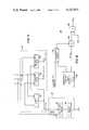
- FIG. 1is a simplified block diagram of a surface contouring system according to this invention
- FIG. 2is a more detailed schematic diagram of the pattern projecting unit, detector circuit and portions of the pattern shifting control of FIG. 1;
- FIG. 2Ais a diagram of an alternative pattern projecting unit and pattern shifting control
- FIG. 3is a more detailed block diagram of the scanning circuit and pattern shifting control of FIG. 1;
- FIG. 4is a more detailed block diagram of the storage circuit of FIG. 1;
- FIG. 5is a more detailed block diagram of the arithmetic circuit of FIG. 1;
- FIG. 6is a block diagram of an alternative arithmetic circuit
- FIG. 7is a more detailed block diagram of a multi-function implementation of the trigonometric function generator of FIG. 1;
- FIG. 8is a more detailed block diagram of an implementation of the calculator circuit of FIG. 1;
- FIG. 9is a flow chart showing the simplified method of this invention.
- the inventionmay be accomplished by projecting a sinusoidal pattern on a surface to be tested. Some means is necessary for shifting the pattern relative to the test surface.
- the patternis shifted in three discrete steps at one-quarter period intervals of the pattern: the first or zero step; the second step at a one-quarter period (90°) interval from the first step; and a third step at an additional one-quarter period interval and a half period (180°) from the first.
- At least one detectorfor sensing through the mask the intensity of the radiation from the test surface. More typically, there is an array of such detectors so that the process is carried out at each of the detectors simultaneously. For satisfactory results, the detector aperture is greater than the spacing of the fringes of the pattern by a factor of five or more.
- Each detectoris scanned at each step to obtain from the detector a signal representative of the level of intensity at each detector. These intensity levels are stored separately for each detector for each step.
- the means for storingmay include a sample and hold circuit for receiving the scanned inputs and submitting them to an A to D converter, which then delivers them to a digital memory for subsequent processing. For each detector, the first and third intensities are combined additively to produce the d.c.
- the cosinusoidal and sinusoidal spatial frequency amplitudesare used to generate any one of a number of trigonometric functions of the phase angle of the radiation from the test surface, e.g. sine, cosine, tan, cotan, sine 2 , and cosine 2 .
- the phase angleis specifically determined and from it the height of the surface at each position may be simply calculated.
- the intensity distribution on the test surfaceis given by: ##EQU1## where h(x,y) is the height of the object on the test surface, p is the period of the fringe pattern and ⁇ is the angular tilt of the surface with respect to the optical axis of the pattern projection system.
- Equations (9), (10), and (11)are:
- the term 2K 0represents the d.c. spatial frequency amplitude; 2K 1 cos k ⁇ 0 the cosinusoidal spatial frequency amplitude; and 2K 1 sin cos k ⁇ 0 the sinusoidal spatial frequency amplitude.
- the system 10, FIG. 1includes a pattern projecting unit 12 which projects a sinusoidal pattern onto the object or test surface.
- This patternis sensed by detector circuit 14 through a mask containing the same pattern.
- the patternmay be any reference ruling, e.g. Ronchi ruling or other pattern in which the relationship of the light and dark portions or fringes is sinusoidal.
- the fringesmay be straight, curved, circular or any other shape desired for use with a particular test surface.
- the shifting of the projected patternis controlled by the pattern shifting control 16, which shifts the pattern in three steps at one-quarter period intervals of the pattern. At each of those steps, detector 14 is read out by scanning circuit 18, whose output is delivered to storage circuit 20.
- the cosinusoidal and sinusoidal amplitudesare combined in a trigonometric function generator 32 to provide a trigonometric function of the phase angle, which is then delivered to height calculator circuit 34, which determines the phase angle and from it the actual height (h(x,y)) ⁇ 0 at each point of the surface monitored by a detector.
- Scanning circuit 18, FIG. 3includes an X scan 60 driven by clock control 62, and a Y scan 64 driven by X scan 60.
- An end of scan circuit 66monitors the scanning operation and counter 68 is used to initiate a step request to pattern shifting control 16.
- pulses from clock control 62cause X scan 60 to read out a row of detectors in the array of detector circuit 14.
- the signal from the X scan outputcauses Y scan 64 to step to the next row.
- the signalis provided to end scan 66 which upon the subsequent arrival of the last scan signal from X scan 60 produces an end of scan signal which turns off clock control 62 and steps counter 68 from the first step to the second.
- Storage circuit 20may include sample and hold circuit 72, FIG. 4, which supplies the intensity level sensed by detector circuit 14 to A to D converter 74, which converts the signals to digital form for storage in digital memory 76.
- a to D converter 74which converts the signals to digital form for storage in digital memory 76.
- Each of the intensities sensed at each step by each of the detectors in detector circuit 14is separately stored in memory 76.
- Arithmetic circuit 22may include simply an adder circuit 80, FIG. 5, and two subtractor circuits 82, 84. For each detector, the intensities from the first and third steps I 1 and I 3 are added by adder circuit 80 to produce the d.c. amplitude 2K 0 . The same intensities I 1 and I 3 may be subtracted in circuit 82 to provide the cosinusoidal amplitude 2K 1 cos k ⁇ 0 . The subtractor circuit 84 may subtract from the d.c. amplitude the intensity I 2 from the second step to produce the sinusoidal amplitude 2K 1 sin k ⁇ 0 . The cosinusoidal and sinusoidal amplitudes thus obtained may be forwarded directly to the trigonometric function generator 32.
- Sign determining circuit 30may include a multiplication circuit 90 which multiplies by 2 the intensity level I 2 derived from the second step, and a subtractor circuit 92, which subtracts from the d.c. amplitude (I 1 +I 3 ) from adder circuit 80 the output of multiplier circuit 90, I 2 . If the d.c. amplitude is greater than twice I 2 , the output of subtractor circuit 92 is sensed by polarity sensor 94 to indicate a positive sign. If, conversely, the value of 2(I 2 ) is greater than the d.c. amplitude, then polarity sensor 94 indicates that the sign is negative.
- a halving circuitcould be supplied in the d.c. amplitude input from adder circuit 80.
- arithmetic circuit 22'may include adder circuit 100, divider circuit 102 or multiplier circuit 104, and two subtractor circuits 106 and 108. From this circuit the outputs K 1 cos k ⁇ from subtractor circuit 106 and K 1 sin k ⁇ from subtractor circuit 108 are obtained directly without the additional factor of 2, primarly from the use of divider circuit 102 which halves the input, or alternatively the multiplying circuit 104 which doubles the complementary input. As a result of this factor of 2 being removed from the arithmetic circuit, the output of subtractor circuit 108, that is K 1 sin k ⁇ 0 signal, may be fed directly to polarity sensor 94 to determine sign without multiplying circuit 90 and subtractor circuit 92.
- Trigonometric function generator 32may include simply a divider circuit 110 for obtaining the trigonometric function, tangent, by simply dividing the sinusoidal amplitude K 1 sin k 0 by the cosinusoidal amplitude K 1 cos k ⁇ 0 .
- trigonometric function generator 32may include squaring circuits 112 and 114, adder circuit 116, square root circuit 122, and either divider circuit 124 for obtaining the trigonometric function cosine by dividing the cosine by the square root of the sum of the cosine squared and sine squared, or divider circuit 126 for obtaining the trigonometric function sine by dividing the sine by the square root of the sum of the cosine squared and sine squared.
- any one of these outputs: tangent, cosine squared, sine squared, cosine, or sine,may be used in height calculator circuit 34.
- the squared functions of cosine and sineare preferred since their values run only between zero and +1, making for a limited table memory requirement.
- Height calculator circuit 34includes a trigonometric function table memory and cycle circuit 130, and comparator circuit 132 which compares the incoming trigonometric function such as cosine squared, for example, with the values of that function stored in table 130. When a match is found, comparator circuit 132 enables gate 134 to pass the corresponding phase angle ⁇ equal to k ⁇ 0 to multiplier circuit 136, where it is multiplied by the value of 1/k, or p/2 ⁇ , to obtain the height ⁇ 0 of the surface at the position monitored by the particular detector.
- comparator circuit 132which compares the incoming trigonometric function such as cosine squared, for example, with the values of that function stored in table 130. When a match is found, comparator circuit 132 enables gate 134 to pass the corresponding phase angle ⁇ equal to k ⁇ 0 to multiplier circuit 136, where it is multiplied by the value of 1/k, or p/2 ⁇ , to obtain the height ⁇ 0 of the surface at the position monitored by
- the method of this inventionmay be more easily understood from the flow diagram, FIG. 9, wherein at the first or zero step the first scan is made and the level of intensity I 1 is stored for each detector 140. Following this, the pattern is shifted by one quarter period 144, and the second scan and store of I 2 is accomplished, 146. The optical path length difference is then shifted by a quarter period to obtain a total shift of a half period 148, and the third scan and store of intensity I 3 is accomplished, 150. Then the d.c. amplitude is calculated from I 1 +I 3 , 152. The cosine amplitude is calculated from I 1 -I 3 , 154, and the sine amplitude is calculated from I 1 +I 3 -I 2 , 156.
- the cosine and sine amplitudesare combined to generate any particular trigonometric function of the phase angle.
- This phase angleis then determined, 160, and used to calculate the height ⁇ 0 of the surface at a particular detector 162.
- the methodis carried out for each of the detectors in the detector circuit.
- the sign of ⁇ 0may be determined by comparing the d.c. amplitude term I 1 +I 3 with twice the intensity I 2 , 164; and if the d.c. amplitude term is greater indicating a positive sign and if it is smaller indicating a negative sign.
- arithmetic circuit 22in conjunction with storage circuit 20, as well as those performed by the sign-determining circuit 30, trigonometric function generator 32, and height calculator 34, may be carried out using a micro-processor such as an Intel-8080 or by a properly programmed digital mini-computer.
- the table look-up function of height calculator circuit 34may be implemented by an EPROM.
- these outputsmay be further processed, as is known in the prior art, to detect and eliminate any tilt and tip factors between the two surfaces being compared and to ascertain the n order determination to resolve any uncertainties of ⁇ 0 between zero and p/2. Since the resolution of this system is not critically dependent on the spatial frequency or period of the projected pattern a higher F number optical system can be used to obtain the same or increased resolution while providing even more improved depth of field or height operating range.
Landscapes
- Engineering & Computer Science (AREA)
- Computer Vision & Pattern Recognition (AREA)
- Physics & Mathematics (AREA)
- General Physics & Mathematics (AREA)
- Length Measuring Devices By Optical Means (AREA)
Abstract
Description
I.sub.1 (x,y)=k.sub.0 +k.sub.1 cos kΔ.sub.0 (12)
I.sub.2 (x,y)=k.sub.0 -k.sub.1 sin kΔ.sub.0 (13)
I.sub.3 (x,y)=k.sub.0 -k.sub.1 cosΔ.sub.0 (14)
I.sub.1 +I.sub.3 =2K.sub.0 (15)
I.sub.1 -I.sub.3 =2K.sub.1 cos kΔ.sub.0 (16)
I.sub.1 +I.sub.3 -I.sub.2 =2K.sub.1 sin kΔ.sub.0 (17)
Claims (14)
Priority Applications (1)
| Application Number | Priority Date | Filing Date | Title |
|---|---|---|---|
| US05/969,241US4212073A (en) | 1978-12-13 | 1978-12-13 | Method and system for surface contouring |
Applications Claiming Priority (1)
| Application Number | Priority Date | Filing Date | Title |
|---|---|---|---|
| US05/969,241US4212073A (en) | 1978-12-13 | 1978-12-13 | Method and system for surface contouring |
Publications (1)
| Publication Number | Publication Date |
|---|---|
| US4212073Atrue US4212073A (en) | 1980-07-08 |
Family
ID=25515343
Family Applications (1)
| Application Number | Title | Priority Date | Filing Date |
|---|---|---|---|
| US05/969,241Expired - LifetimeUS4212073A (en) | 1978-12-13 | 1978-12-13 | Method and system for surface contouring |
Country Status (1)
| Country | Link |
|---|---|
| US (1) | US4212073A (en) |
Cited By (59)
| Publication number | Priority date | Publication date | Assignee | Title |
|---|---|---|---|---|
| US4373816A (en)* | 1981-01-09 | 1983-02-15 | Morvue, Inc. | Scanning beam optical position determining apparatus and method |
| US4412121A (en)* | 1981-08-28 | 1983-10-25 | S R I International | Implement positioning apparatus and process |
| DE3328753A1 (en)* | 1982-08-18 | 1984-02-23 | Novon, Inc., 01907 Swampscott, Mass. | METHOD AND DEVICE FOR IMAGING SCENES AND AREAS |
| WO1984003142A1 (en)* | 1983-02-14 | 1984-08-16 | Coe Mfg Co | Scanning beam optical position determining apparatus and method |
| EP0182469A1 (en)* | 1984-09-14 | 1986-05-28 | New York Institute Of Technology | Apparatus and method for obtaining surface profilometry and three dimensional surface contours |
| EP0165385A3 (en)* | 1984-04-21 | 1986-12-10 | ELTRO GmbH Gesellschaft für Strahlungstechnik | Process and circuit for the distance and angle independent measurement of equal distance points from a common reference point |
| US4641972A (en)* | 1984-09-14 | 1987-02-10 | New York Institute Of Technology | Method and apparatus for surface profilometry |
| US4776698A (en)* | 1986-08-04 | 1988-10-11 | Eastman Kodak Company | Measuring |
| US4794550A (en)* | 1986-10-15 | 1988-12-27 | Eastman Kodak Company | Extended-range moire contouring |
| US4818108A (en)* | 1987-12-14 | 1989-04-04 | Hughes Optical Products, Inc. | Phase modulated ronchi testing of aspheric surfaces |
| US4846576A (en)* | 1985-05-20 | 1989-07-11 | Fujitsu Limited | Method for measuring a three-dimensional position of an object |
| WO1990007691A1 (en)* | 1988-12-23 | 1990-07-12 | Klaus Pfister | Process and device for observing moire patterns on test surfaces by moireing with phase shifts |
| DE3843396C1 (en)* | 1988-12-23 | 1990-07-26 | Klaus 8206 Bruckmuehl De Pfister | Method and device for observing moiré patterns of surfaces under investigation in conjunction with the application of the projection moiré method with phase shifts |
| US4984893A (en)* | 1989-12-01 | 1991-01-15 | Wyko Corporation | Phase shifting device and method |
| DE3934423C1 (en)* | 1989-10-14 | 1991-04-25 | Fraunhofer-Gesellschaft Zur Foerderung Der Angewandten Forschung Ev, 8000 Muenchen, De | Camera photographing topography of test piece surface - produces Moire image using CCD sensors recording phase shift between object grating and camera reference grating |
| DE4006343A1 (en)* | 1990-03-01 | 1991-09-05 | Bernd Dr Breuckmann | Evaluating strip patterns for optical measuring process - modulating by carrier frequency and imaging on sensor for evaluating by phase shift algorithm |
| US5069548A (en)* | 1990-08-08 | 1991-12-03 | Industrial Technology Institute | Field shift moire system |
| US5075560A (en)* | 1990-09-20 | 1991-12-24 | Eastman Kodak Company | Moire distance measurements using a grating printed on or attached to a surface |
| US5075562A (en)* | 1990-09-20 | 1991-12-24 | Eastman Kodak Company | Method and apparatus for absolute Moire distance measurements using a grating printed on or attached to a surface |
| DE4120115A1 (en)* | 1991-06-19 | 1992-12-24 | Volkswagen Ag | CONTACT-FREE WORKING METHOD FOR DETERMINING THE SPATIAL COORDINATES OF OBJECT POINTS |
| US5175601A (en)* | 1991-10-15 | 1992-12-29 | Electro-Optical Information Systems | High-speed 3-D surface measurement surface inspection and reverse-CAD system |
| US5189493A (en)* | 1990-11-02 | 1993-02-23 | Industrial Technology Institute | Moire contouring camera |
| US5262844A (en)* | 1990-07-03 | 1993-11-16 | Bertin & Cie | Apparatus for determining the three-dimensional shape of an object optically without contact |
| US5289264A (en)* | 1991-09-26 | 1994-02-22 | Hans Steinbichler | Method and apparatus for ascertaining the absolute coordinates of an object |
| WO1994005968A1 (en)* | 1992-09-08 | 1994-03-17 | Fitts John M | Hidden change distribution grating and use in 3d moire measurement sensors and cmm applications |
| US5307152A (en)* | 1992-09-29 | 1994-04-26 | Industrial Technology Institute | Moire inspection system |
| US5307153A (en)* | 1990-06-19 | 1994-04-26 | Fujitsu Limited | Three-dimensional measuring apparatus |
| US5309222A (en)* | 1991-07-16 | 1994-05-03 | Mitsubishi Denki Kabushiki Kaisha | Surface undulation inspection apparatus |
| DE4313860A1 (en)* | 1993-04-28 | 1994-11-03 | Ralf Lampalzer | Optical sensor for shape recognition of three-dimensional objects |
| US5434669A (en)* | 1990-10-23 | 1995-07-18 | Olympus Optical Co., Ltd. | Measuring interferometric endoscope having a laser radiation source |
| US5436462A (en)* | 1993-12-21 | 1995-07-25 | United Technologies Optical Systems | Video contour measurement system employing moire interferometry having a beat frequency pattern |
| US5450204A (en)* | 1992-03-30 | 1995-09-12 | Sharp Kabushiki Kaisha | Inspecting device for inspecting printed state of cream solder |
| WO1997006509A1 (en)* | 1995-08-03 | 1997-02-20 | Gim Systems Ltd. | Imaging measurement system |
| US5636025A (en)* | 1992-04-23 | 1997-06-03 | Medar, Inc. | System for optically measuring the surface contour of a part using more fringe techniques |
| US5646733A (en)* | 1996-01-29 | 1997-07-08 | Medar, Inc. | Scanning phase measuring method and system for an object at a vision station |
| DE19738480C1 (en)* | 1997-09-03 | 1998-11-26 | Bernward Maehner | Optical measuring method for 3-dimensional object |
| US6122062A (en)* | 1999-05-03 | 2000-09-19 | Fanuc Robotics North America, Inc. | 3-D camera |
| US6381026B1 (en) | 1999-03-15 | 2002-04-30 | Lifecell Corp. | Method of measuring the contour of a biological surface |
| US20020093664A1 (en)* | 2000-02-09 | 2002-07-18 | Erland Max | Arrangement and method for measuring surface irregularities |
| US20020163573A1 (en)* | 2001-04-11 | 2002-11-07 | Bieman Leonard H. | Imaging system |
| US6486963B1 (en) | 2000-06-20 | 2002-11-26 | Ppt Vision, Inc. | Precision 3D scanner base and method for measuring manufactured parts |
| US6488390B1 (en) | 1998-03-19 | 2002-12-03 | Ppt Vision, Inc. | Color-adjusted camera light and method |
| US6501554B1 (en) | 2000-06-20 | 2002-12-31 | Ppt Vision, Inc. | 3D scanner and method for measuring heights and angles of manufactured parts |
| US6509559B1 (en) | 2000-06-20 | 2003-01-21 | Ppt Vision, Inc. | Binary optical grating and method for generating a moire pattern for 3D imaging |
| US6522777B1 (en) | 1998-07-08 | 2003-02-18 | Ppt Vision, Inc. | Combined 3D- and 2D-scanning machine-vision system and method |
| US20030111532A1 (en)* | 2001-12-14 | 2003-06-19 | General Electric Company | Self-referencing system for light gauge images |
| US20040105580A1 (en)* | 2002-11-22 | 2004-06-03 | Hager Gregory D. | Acquisition of three-dimensional images by an active stereo technique using locally unique patterns |
| US20040151369A1 (en)* | 2003-01-31 | 2004-08-05 | Sirona Dental Systems Gmbh | Method and system for imaging an object |
| US6788411B1 (en) | 1999-07-08 | 2004-09-07 | Ppt Vision, Inc. | Method and apparatus for adjusting illumination angle |
| US20050111726A1 (en)* | 1998-07-08 | 2005-05-26 | Hackney Joshua J. | Parts manipulation and inspection system and method |
| US7353954B1 (en) | 1998-07-08 | 2008-04-08 | Charles A. Lemaire | Tray flipper and method for parts inspection |
| EP1715291A3 (en)* | 2005-04-21 | 2008-06-25 | Gom | Projector for a system for three dimensional optical object measurement |
| US7740371B1 (en) | 1998-03-19 | 2010-06-22 | Charles A. Lemaire | Method and apparatus for pulsed L.E.D. illumination for a camera |
| WO2010107434A1 (en)* | 2009-03-19 | 2010-09-23 | General Electric Company | Optical gage and three-dimensional surface profile measurement method |
| US20110228082A1 (en)* | 2010-03-16 | 2011-09-22 | Kuang-Pu Wen | Measuring system for a 3D Object |
| WO2015033167A1 (en)* | 2013-09-09 | 2015-03-12 | Cadscan Limited | Scanner |
| US9591288B2 (en) | 2013-06-07 | 2017-03-07 | Young Optics Inc. | Three-dimensional image apparatus and operation method thereof |
| US10997738B2 (en)* | 2017-03-08 | 2021-05-04 | Omron Corporation | Three-dimensional-shape measurement device, three-dimensional-shape measurement method, and program |
| US20220074738A1 (en)* | 2019-04-11 | 2022-03-10 | Hewlett-Packard Development Company, L.P. | Three dimensional imaging |
Citations (6)
| Publication number | Priority date | Publication date | Assignee | Title |
|---|---|---|---|---|
| US3828126A (en)* | 1973-04-13 | 1974-08-06 | American Express Invest | Real time interferometry |
| US3866052A (en)* | 1973-11-02 | 1975-02-11 | Dynell Elec | Methods for generating signals defining three-dimensional object surfaces |
| US3967114A (en)* | 1974-01-10 | 1976-06-29 | Compagnie Industrielle Des Lasers | Device for determining the profile of a surface |
| US4088408A (en)* | 1976-11-08 | 1978-05-09 | The United States Of America As Represented By The Administrator Of The National Aeronautics And Space Administration | Device for measuring the contour of a surface |
| US4139304A (en)* | 1977-02-10 | 1979-02-13 | National Research Development Corporation | Methods and apparatus for measuring variations in distance to a surface |
| US4145991A (en)* | 1975-08-27 | 1979-03-27 | Solid Photography Inc. | Arrangement for sensing the geometric characteristics of an object |
- 1978
- 1978-12-13USUS05/969,241patent/US4212073A/ennot_activeExpired - Lifetime
Patent Citations (6)
| Publication number | Priority date | Publication date | Assignee | Title |
|---|---|---|---|---|
| US3828126A (en)* | 1973-04-13 | 1974-08-06 | American Express Invest | Real time interferometry |
| US3866052A (en)* | 1973-11-02 | 1975-02-11 | Dynell Elec | Methods for generating signals defining three-dimensional object surfaces |
| US3967114A (en)* | 1974-01-10 | 1976-06-29 | Compagnie Industrielle Des Lasers | Device for determining the profile of a surface |
| US4145991A (en)* | 1975-08-27 | 1979-03-27 | Solid Photography Inc. | Arrangement for sensing the geometric characteristics of an object |
| US4088408A (en)* | 1976-11-08 | 1978-05-09 | The United States Of America As Represented By The Administrator Of The National Aeronautics And Space Administration | Device for measuring the contour of a surface |
| US4139304A (en)* | 1977-02-10 | 1979-02-13 | National Research Development Corporation | Methods and apparatus for measuring variations in distance to a surface |
Cited By (96)
| Publication number | Priority date | Publication date | Assignee | Title |
|---|---|---|---|---|
| US4373816A (en)* | 1981-01-09 | 1983-02-15 | Morvue, Inc. | Scanning beam optical position determining apparatus and method |
| US4412121A (en)* | 1981-08-28 | 1983-10-25 | S R I International | Implement positioning apparatus and process |
| DE3328753A1 (en)* | 1982-08-18 | 1984-02-23 | Novon, Inc., 01907 Swampscott, Mass. | METHOD AND DEVICE FOR IMAGING SCENES AND AREAS |
| WO1984003142A1 (en)* | 1983-02-14 | 1984-08-16 | Coe Mfg Co | Scanning beam optical position determining apparatus and method |
| EP0165385A3 (en)* | 1984-04-21 | 1986-12-10 | ELTRO GmbH Gesellschaft für Strahlungstechnik | Process and circuit for the distance and angle independent measurement of equal distance points from a common reference point |
| EP0182469A1 (en)* | 1984-09-14 | 1986-05-28 | New York Institute Of Technology | Apparatus and method for obtaining surface profilometry and three dimensional surface contours |
| US4641972A (en)* | 1984-09-14 | 1987-02-10 | New York Institute Of Technology | Method and apparatus for surface profilometry |
| US4657394A (en)* | 1984-09-14 | 1987-04-14 | New York Institute Of Technology | Apparatus and method for obtaining three dimensional surface contours |
| US4846576A (en)* | 1985-05-20 | 1989-07-11 | Fujitsu Limited | Method for measuring a three-dimensional position of an object |
| US4776698A (en)* | 1986-08-04 | 1988-10-11 | Eastman Kodak Company | Measuring |
| US4794550A (en)* | 1986-10-15 | 1988-12-27 | Eastman Kodak Company | Extended-range moire contouring |
| US4818108A (en)* | 1987-12-14 | 1989-04-04 | Hughes Optical Products, Inc. | Phase modulated ronchi testing of aspheric surfaces |
| WO1990007691A1 (en)* | 1988-12-23 | 1990-07-12 | Klaus Pfister | Process and device for observing moire patterns on test surfaces by moireing with phase shifts |
| DE3843396C1 (en)* | 1988-12-23 | 1990-07-26 | Klaus 8206 Bruckmuehl De Pfister | Method and device for observing moiré patterns of surfaces under investigation in conjunction with the application of the projection moiré method with phase shifts |
| US5202749A (en)* | 1988-12-23 | 1993-04-13 | Klaus Pfister | Process and device for observing moire patterns of surfaces to be tested by application of the moire method using phase shifting |
| DE3907430C1 (en)* | 1988-12-23 | 1991-03-21 | Klaus 8206 Bruckmuehl De Pfister | |
| DE3934423C1 (en)* | 1989-10-14 | 1991-04-25 | Fraunhofer-Gesellschaft Zur Foerderung Der Angewandten Forschung Ev, 8000 Muenchen, De | Camera photographing topography of test piece surface - produces Moire image using CCD sensors recording phase shift between object grating and camera reference grating |
| US4984893A (en)* | 1989-12-01 | 1991-01-15 | Wyko Corporation | Phase shifting device and method |
| DE4006343A1 (en)* | 1990-03-01 | 1991-09-05 | Bernd Dr Breuckmann | Evaluating strip patterns for optical measuring process - modulating by carrier frequency and imaging on sensor for evaluating by phase shift algorithm |
| US5307153A (en)* | 1990-06-19 | 1994-04-26 | Fujitsu Limited | Three-dimensional measuring apparatus |
| US5262844A (en)* | 1990-07-03 | 1993-11-16 | Bertin & Cie | Apparatus for determining the three-dimensional shape of an object optically without contact |
| US5069548A (en)* | 1990-08-08 | 1991-12-03 | Industrial Technology Institute | Field shift moire system |
| US5075560A (en)* | 1990-09-20 | 1991-12-24 | Eastman Kodak Company | Moire distance measurements using a grating printed on or attached to a surface |
| US5075562A (en)* | 1990-09-20 | 1991-12-24 | Eastman Kodak Company | Method and apparatus for absolute Moire distance measurements using a grating printed on or attached to a surface |
| US5434669A (en)* | 1990-10-23 | 1995-07-18 | Olympus Optical Co., Ltd. | Measuring interferometric endoscope having a laser radiation source |
| US5189493A (en)* | 1990-11-02 | 1993-02-23 | Industrial Technology Institute | Moire contouring camera |
| DE4120115A1 (en)* | 1991-06-19 | 1992-12-24 | Volkswagen Ag | CONTACT-FREE WORKING METHOD FOR DETERMINING THE SPATIAL COORDINATES OF OBJECT POINTS |
| US5309222A (en)* | 1991-07-16 | 1994-05-03 | Mitsubishi Denki Kabushiki Kaisha | Surface undulation inspection apparatus |
| US5289264A (en)* | 1991-09-26 | 1994-02-22 | Hans Steinbichler | Method and apparatus for ascertaining the absolute coordinates of an object |
| US5175601A (en)* | 1991-10-15 | 1992-12-29 | Electro-Optical Information Systems | High-speed 3-D surface measurement surface inspection and reverse-CAD system |
| US5450204A (en)* | 1992-03-30 | 1995-09-12 | Sharp Kabushiki Kaisha | Inspecting device for inspecting printed state of cream solder |
| US5636025A (en)* | 1992-04-23 | 1997-06-03 | Medar, Inc. | System for optically measuring the surface contour of a part using more fringe techniques |
| WO1994005968A1 (en)* | 1992-09-08 | 1994-03-17 | Fitts John M | Hidden change distribution grating and use in 3d moire measurement sensors and cmm applications |
| US5319445A (en)* | 1992-09-08 | 1994-06-07 | Fitts John M | Hidden change distribution grating and use in 3D moire measurement sensors and CMM applications |
| US5307152A (en)* | 1992-09-29 | 1994-04-26 | Industrial Technology Institute | Moire inspection system |
| DE4313860A1 (en)* | 1993-04-28 | 1994-11-03 | Ralf Lampalzer | Optical sensor for shape recognition of three-dimensional objects |
| US5436462A (en)* | 1993-12-21 | 1995-07-25 | United Technologies Optical Systems | Video contour measurement system employing moire interferometry having a beat frequency pattern |
| US5867604A (en)* | 1995-08-03 | 1999-02-02 | Ben-Levy; Meir | Imaging measurement system |
| WO1997006509A1 (en)* | 1995-08-03 | 1997-02-20 | Gim Systems Ltd. | Imaging measurement system |
| EP0877914A4 (en)* | 1996-01-29 | 2000-05-31 | Medar Inc | Scanning phase measuring method and system for an object at a vision station |
| US5646733A (en)* | 1996-01-29 | 1997-07-08 | Medar, Inc. | Scanning phase measuring method and system for an object at a vision station |
| USRE39978E1 (en) | 1996-01-29 | 2008-01-01 | Ismeca Europe Semiconductor Sa | Scanning phase measuring method and system for an object at a vision station |
| DE19738480C1 (en)* | 1997-09-03 | 1998-11-26 | Bernward Maehner | Optical measuring method for 3-dimensional object |
| US8159146B1 (en) | 1998-03-19 | 2012-04-17 | Lemaire Illumination Technologies, Llc | Apparatus and method for pulsed L.E.D. illumination |
| US8643305B2 (en) | 1998-03-19 | 2014-02-04 | Lemaire Illumination Technologies, Llc | Apparatus for L.E.D. illumination |
| US8362712B1 (en) | 1998-03-19 | 2013-01-29 | Led Tech Development, Llc | Apparatus and method for L.E.D. illumination |
| US8829808B1 (en) | 1998-03-19 | 2014-09-09 | Led Tech Development, Llc | Apparatus and method for pulsed L.E.D. illumination |
| US6488390B1 (en) | 1998-03-19 | 2002-12-03 | Ppt Vision, Inc. | Color-adjusted camera light and method |
| US7740371B1 (en) | 1998-03-19 | 2010-06-22 | Charles A. Lemaire | Method and apparatus for pulsed L.E.D. illumination for a camera |
| US6808287B2 (en) | 1998-03-19 | 2004-10-26 | Ppt Vision, Inc. | Method and apparatus for a pulsed L.E.D. illumination source |
| US7393119B2 (en) | 1998-03-19 | 2008-07-01 | Charles A. Lemaire | Method and apparatus for constant light output pulsed L.E.D. illumination |
| US20030095406A1 (en)* | 1998-03-19 | 2003-05-22 | Ppt Vision, Inc. | Method and apparatus for a pulsed L.E.D. illumination source |
| US9907137B1 (en) | 1998-03-19 | 2018-02-27 | Lemaire Illumination Technologies, Llc | Pulsed L.E.D. illumination |
| US20070133199A1 (en)* | 1998-03-19 | 2007-06-14 | Charles Lemaire | Method and apparatus for a pulsed l.e.d. illumination |
| US7186000B2 (en) | 1998-03-19 | 2007-03-06 | Lebens Gary A | Method and apparatus for a variable intensity pulsed L.E.D. light |
| US20090078620A1 (en)* | 1998-07-08 | 2009-03-26 | Charles A. Lemaire | Tray flipper, tray, and method for parts inspection |
| US8408379B2 (en) | 1998-07-08 | 2013-04-02 | Charles A. Lemaire | Parts manipulation, inspection, and replacement |
| US8286780B2 (en) | 1998-07-08 | 2012-10-16 | Charles A. Lemaire | Parts manipulation, inspection, and replacement system and method |
| US8056700B2 (en) | 1998-07-08 | 2011-11-15 | Charles A. Lemaire | Tray flipper, tray, and method for parts inspection |
| US7773209B2 (en) | 1998-07-08 | 2010-08-10 | Charles A. Lemaire | Method and apparatus for parts manipulation, inspection, and replacement |
| US20050111726A1 (en)* | 1998-07-08 | 2005-05-26 | Hackney Joshua J. | Parts manipulation and inspection system and method |
| US6956963B2 (en) | 1998-07-08 | 2005-10-18 | Ismeca Europe Semiconductor Sa | Imaging for a machine-vision system |
| US7719670B2 (en) | 1998-07-08 | 2010-05-18 | Charles A. Lemaire | Parts manipulation, inspection, and replacement system and method |
| US20090180679A1 (en)* | 1998-07-08 | 2009-07-16 | Charles A. Lemaire | Method and apparatus for parts manipulation, inspection, and replacement |
| US6603103B1 (en) | 1998-07-08 | 2003-08-05 | Ppt Vision, Inc. | Circuit for machine-vision system |
| US20090073427A1 (en)* | 1998-07-08 | 2009-03-19 | Charles A. Lemaire | Parts manipulation, inspection, and replacement system and method |
| US7397550B2 (en) | 1998-07-08 | 2008-07-08 | Charles A. Lemaire | Parts manipulation and inspection system and method |
| US7353954B1 (en) | 1998-07-08 | 2008-04-08 | Charles A. Lemaire | Tray flipper and method for parts inspection |
| US6522777B1 (en) | 1998-07-08 | 2003-02-18 | Ppt Vision, Inc. | Combined 3D- and 2D-scanning machine-vision system and method |
| US6381026B1 (en) | 1999-03-15 | 2002-04-30 | Lifecell Corp. | Method of measuring the contour of a biological surface |
| US6122062A (en)* | 1999-05-03 | 2000-09-19 | Fanuc Robotics North America, Inc. | 3-D camera |
| US6788411B1 (en) | 1999-07-08 | 2004-09-07 | Ppt Vision, Inc. | Method and apparatus for adjusting illumination angle |
| US7557920B2 (en) | 1999-07-08 | 2009-07-07 | Lebens Gary A | Method and apparatus for auto-adjusting illumination |
| US7142301B2 (en) | 1999-07-08 | 2006-11-28 | Ppt Vision | Method and apparatus for adjusting illumination angle |
| US20020093664A1 (en)* | 2000-02-09 | 2002-07-18 | Erland Max | Arrangement and method for measuring surface irregularities |
| US6577404B2 (en)* | 2000-02-09 | 2003-06-10 | Volvo Personvagnar Ab | Arrangement and method for measuring surface irregularities |
| US6509559B1 (en) | 2000-06-20 | 2003-01-21 | Ppt Vision, Inc. | Binary optical grating and method for generating a moire pattern for 3D imaging |
| US6486963B1 (en) | 2000-06-20 | 2002-11-26 | Ppt Vision, Inc. | Precision 3D scanner base and method for measuring manufactured parts |
| US6501554B1 (en) | 2000-06-20 | 2002-12-31 | Ppt Vision, Inc. | 3D scanner and method for measuring heights and angles of manufactured parts |
| US20020163573A1 (en)* | 2001-04-11 | 2002-11-07 | Bieman Leonard H. | Imaging system |
| US20030111532A1 (en)* | 2001-12-14 | 2003-06-19 | General Electric Company | Self-referencing system for light gauge images |
| US20040105580A1 (en)* | 2002-11-22 | 2004-06-03 | Hager Gregory D. | Acquisition of three-dimensional images by an active stereo technique using locally unique patterns |
| US7103212B2 (en) | 2002-11-22 | 2006-09-05 | Strider Labs, Inc. | Acquisition of three-dimensional images by an active stereo technique using locally unique patterns |
| WO2004049255A3 (en)* | 2002-11-22 | 2004-07-29 | Strider Labs Inc | Acquisition of three-dimensional images by an active stereo technique using locally unique patterns |
| US20040151369A1 (en)* | 2003-01-31 | 2004-08-05 | Sirona Dental Systems Gmbh | Method and system for imaging an object |
| US7522764B2 (en)* | 2003-01-31 | 2009-04-21 | Sirona Dental Systems Gmbh | Method and system for imaging an object |
| EP1715291A3 (en)* | 2005-04-21 | 2008-06-25 | Gom | Projector for a system for three dimensional optical object measurement |
| GB2480578A (en)* | 2009-03-19 | 2011-11-23 | Gen Electric | Optical gage and three-dimensional surface profile measurement method |
| GB2480578B (en)* | 2009-03-19 | 2013-08-14 | Gen Electric | Optical gauge and three-dimensional surface profile measurement method |
| WO2010107434A1 (en)* | 2009-03-19 | 2010-09-23 | General Electric Company | Optical gage and three-dimensional surface profile measurement method |
| US20110228082A1 (en)* | 2010-03-16 | 2011-09-22 | Kuang-Pu Wen | Measuring system for a 3D Object |
| US9420235B2 (en) | 2010-03-16 | 2016-08-16 | Test Research, Inc. | Measuring system for a 3D object |
| US9591288B2 (en) | 2013-06-07 | 2017-03-07 | Young Optics Inc. | Three-dimensional image apparatus and operation method thereof |
| WO2015033167A1 (en)* | 2013-09-09 | 2015-03-12 | Cadscan Limited | Scanner |
| US10997738B2 (en)* | 2017-03-08 | 2021-05-04 | Omron Corporation | Three-dimensional-shape measurement device, three-dimensional-shape measurement method, and program |
| US20220074738A1 (en)* | 2019-04-11 | 2022-03-10 | Hewlett-Packard Development Company, L.P. | Three dimensional imaging |
Similar Documents
| Publication | Publication Date | Title |
|---|---|---|
| US4212073A (en) | Method and system for surface contouring | |
| US4225240A (en) | Method and system for determining interferometric optical path length difference | |
| US4641972A (en) | Method and apparatus for surface profilometry | |
| US6208416B1 (en) | Method and apparatus for measuring shape of objects | |
| US7385707B2 (en) | Surface profiling apparatus | |
| US6268923B1 (en) | Optical method and system for measuring three-dimensional surface topography of an object having a surface contour | |
| US4340304A (en) | Interferometric method and system | |
| US7948634B2 (en) | Surface profiling apparatus | |
| US4832489A (en) | Two-wavelength phase-shifting interferometer and method | |
| US5339154A (en) | Method and apparatus for optical measurement of objects | |
| US4813782A (en) | Method and apparatus for measuring the floating amount of the magnetic head | |
| US5146293A (en) | Phase-stepping fiber-optic projected fringe system for surface topography measurements | |
| US4776698A (en) | Measuring | |
| JPS62129711A (en) | Method and device for measuring shape error of objects | |
| US5165045A (en) | Method and apparatus for measuring displacement having parallel grating lines perpendicular to a displacement direction for diffracting a light beam | |
| Zhang et al. | Robust, accurate seven-sample phase-shifting algorithm insensitive to nonlinear phase-shift error and second-harmonic distortion: a comparative study | |
| Winther et al. | An ESPI contouring technique in strain analysis | |
| US5436727A (en) | Distance measuring method and apparatus | |
| US5061860A (en) | Deformation measuring method and device using comb-type photosensitive element array | |
| GB2075180A (en) | Method and system for determining interferometric optical path length difference | |
| Kerr et al. | Use of high resolution real-time image processing techniques in generation and analysis of ESPI fringe patterns | |
| Zhang et al. | Spatiotemporal phase unwrapping and its application in fringe projection fiber optic phase-shifting profilometry | |
| JPH0587541A (en) | Two-dimensional information measuring device | |
| JPH07190711A (en) | Interferometer using coherence degree | |
| JP2895874B2 (en) | Method and apparatus for detecting period and phase of interference fringe signal and apparatus for measuring surface inclination and height |
Legal Events
| Date | Code | Title | Description |
|---|---|---|---|
| AS | Assignment | Owner name:MATRIX INSTRUMENTS INC., ONE RAMLAND ROAD ORANGEBU Free format text:ASSIGNMENT OF ASSIGNORS INTEREST.;ASSIGNOR:BALASUBRAMANIAM N.;REEL/FRAME:004322/0112 Effective date:19841026 | |
| AS | Assignment | Owner name:MILES INC. A CORP. OF INDIANA Free format text:MERGER;ASSIGNORS:AGFA CORPORATION A CORP. OF NEW YORK;BAYER USA INC. A CORP. OF DELAWARE;MOBAY CORPORATION A CORP. OF NEW JERSEY (MERGED INTO);REEL/FRAME:006036/0063 Effective date:19911220 | |
| AS | Assignment | Owner name:AGFA CORPORATION, NEW JERSEY Free format text:MERGER;ASSIGNOR:MATRIX INSTRUMENTS, INC.;REEL/FRAME:006903/0877 Effective date:19891219 Owner name:MATRIX INSTRUMENTS, INC., NEW JERSEY Free format text:MERGER;ASSIGNOR:MATRIX IMAGING PALO ALTO CORPORATION;REEL/FRAME:006903/0870 Effective date:19891219 Owner name:MATRIX IMAGING PALO ALTO CORPORATION, NEW YORK Free format text:CHANGE OF NAME;ASSIGNOR:MATRIX ACQUISITION CORPORATION;REEL/FRAME:006903/0862 Effective date:19861112 |