US4211208A - Container for a heat storage medium - Google Patents
Container for a heat storage mediumDownload PDFInfo
- Publication number
- US4211208A US4211208AUS05/860,076US86007677AUS4211208AUS 4211208 AUS4211208 AUS 4211208AUS 86007677 AUS86007677 AUS 86007677AUS 4211208 AUS4211208 AUS 4211208A
- Authority
- US
- United States
- Prior art keywords
- container
- wall means
- heat
- solid
- medium
- Prior art date
- Legal status (The legal status is an assumption and is not a legal conclusion. Google has not performed a legal analysis and makes no representation as to the accuracy of the status listed.)
- Expired - Lifetime
Links
Images


Classifications
- F—MECHANICAL ENGINEERING; LIGHTING; HEATING; WEAPONS; BLASTING
- F28—HEAT EXCHANGE IN GENERAL
- F28D—HEAT-EXCHANGE APPARATUS, NOT PROVIDED FOR IN ANOTHER SUBCLASS, IN WHICH THE HEAT-EXCHANGE MEDIA DO NOT COME INTO DIRECT CONTACT
- F28D20/00—Heat storage plants or apparatus in general; Regenerative heat-exchange apparatus not covered by groups F28D17/00 or F28D19/00
- F28D20/02—Heat storage plants or apparatus in general; Regenerative heat-exchange apparatus not covered by groups F28D17/00 or F28D19/00 using latent heat
- F—MECHANICAL ENGINEERING; LIGHTING; HEATING; WEAPONS; BLASTING
- F28—HEAT EXCHANGE IN GENERAL
- F28F—DETAILS OF HEAT-EXCHANGE AND HEAT-TRANSFER APPARATUS, OF GENERAL APPLICATION
- F28F2265/00—Safety or protection arrangements; Arrangements for preventing malfunction
- F—MECHANICAL ENGINEERING; LIGHTING; HEATING; WEAPONS; BLASTING
- F28—HEAT EXCHANGE IN GENERAL
- F28F—DETAILS OF HEAT-EXCHANGE AND HEAT-TRANSFER APPARATUS, OF GENERAL APPLICATION
- F28F2265/00—Safety or protection arrangements; Arrangements for preventing malfunction
- F28F2265/14—Safety or protection arrangements; Arrangements for preventing malfunction for preventing damage by freezing, e.g. for accommodating volume expansion
- F—MECHANICAL ENGINEERING; LIGHTING; HEATING; WEAPONS; BLASTING
- F28—HEAT EXCHANGE IN GENERAL
- F28F—DETAILS OF HEAT-EXCHANGE AND HEAT-TRANSFER APPARATUS, OF GENERAL APPLICATION
- F28F2265/00—Safety or protection arrangements; Arrangements for preventing malfunction
- F28F2265/26—Safety or protection arrangements; Arrangements for preventing malfunction for allowing differential expansion between elements
- Y—GENERAL TAGGING OF NEW TECHNOLOGICAL DEVELOPMENTS; GENERAL TAGGING OF CROSS-SECTIONAL TECHNOLOGIES SPANNING OVER SEVERAL SECTIONS OF THE IPC; TECHNICAL SUBJECTS COVERED BY FORMER USPC CROSS-REFERENCE ART COLLECTIONS [XRACs] AND DIGESTS
- Y02—TECHNOLOGIES OR APPLICATIONS FOR MITIGATION OR ADAPTATION AGAINST CLIMATE CHANGE
- Y02E—REDUCTION OF GREENHOUSE GAS [GHG] EMISSIONS, RELATED TO ENERGY GENERATION, TRANSMISSION OR DISTRIBUTION
- Y02E60/00—Enabling technologies; Technologies with a potential or indirect contribution to GHG emissions mitigation
- Y02E60/14—Thermal energy storage
Definitions
- the inventionrelates to a container for a heat storage medium having in the solid state a density which varies in accordance with the heat content and being convertible from the solid to the fluid state and from the fluid to the solid state in order to store and release heat.
- Heat storage means of this kindwherein the physical condition of the heat storage medium changes between the fluid and solid state are also referred to as latent heat storage means. They have the advantage that the change in the heat content takes place at a substantially constant temperature, namely at the temperature at which the physical condition changes.
- Latent heat storage means of this kindare used, for example, in heating systems where they assist the heating system during peak requirements and are recharged by the heating system in the event of low heat requirements.
- Latent heat storage means containing Glauber's slat as the heat storage mediumhave been suggested.
- Glauber's saltchanges from the solid to the fluid state at a temperature of 32.4° C. and thereby releases heat in the amount of 357.3 Btu per liter.
- the heat storage mediumWhen heat is removed from the heat storage medium, the latter cools down to its melting point and finally changes into the solid state. Upon further cooling down the volume of the solid medium can be decreased by, for example, compression or recrystallization. Conversely, heating of the solid medium results in a thermal expansion thereof until it changes to the fluid state upon arrival at the melting temperature.
- the problemconsists in the fact that a corresponding increase in the volume of the storage medium resulting from heating the latter has to be accommodated by the heat storage medium container.
- An increase in the volumecannot be equally distributed inside the container owing to the solid state of the medium, which destroys rigid container walls.
- heat storage containers of this kindhave been made of plastic materials which are expandible and can therefore accommodate the increases in volume which occur.
- Plastic receptacles of this kinddo, however, have the disadvantage that the expansions are not completely reversible and so residual expansion remains after each expansion. The numerous increases and decreases in volume which occur periodically inevitably result in a lasting enlargement of the container, which is not tolerable.
- the object of the inventionis to provide a container for a heat storage medium which can accommodate the periodic increases and decreases in the volume of the heat storage medium in the solid state without any lasting change.
- this objectis achieved in a container of the kind first described above by the walls of the container being subjected to an inwardly directed resilient bias.
- provisionsare made to ensure that the container can be of differing volumes, and the bias is selected such that the container assumes a small volume when filled with fluid medium.
- the containerprefferably has inwardly curved walls which are adapted to curve outwardly.
- Resilient spring means curving the walls of the container inwardlycan then engage said walls.
- the containercan also be surrounded by a second rigid closed container with a pressure medium in the space between both containers.
- This pressure mediumcan be a gas or a liquid. In the latter case the static pressure of the liquid acts on the walls of the inside container.
- the inside container itselfcan have flexible walls which in a special embodiment can be resiliently expandible.
- This expansion foldcan have a restoring force which attempts to reduce the volume of the container.
- Spring meanscan also be provided for this purpose.
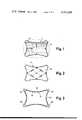
- FIG. 1is a plan view of an inventive container which has been cut open.
- FIG. 2is a view similar to FIG. 1 of another embodiment of an inventive container.
- FIG. 3is a sectional view of an inventive container with leaf springs mounted on the outside.
- FIG. 4is a plan view of an inventive container with compression springs acting on the outer walls of the container.
- FIG. 5is a plan view of an inventive container with a resilient tension band.
- FIG. 6is a plan view of a container disposed in an outer container in accordance with the invention.
- FIG. 7is a sectional view of another embodiment of an inventive container.
- FIG. 8is a sectional view of a further preferred embodiment of an inventive container.
- the container 1 shown in FIG. 1 for a heat storage medium Mwhich for reasons of clarity is not illustrated in the following drawings, is of substantial brick-shaped or cube-shaped configuration. All or some of the walls 2 are inwardly curved, i.e., are concave as seen from the outside. Due to the effect of a pressure inside the container 1 these walls 2 can curve outwardly and then assume the position indicated by the dashed lines in FIG. 1. The container then has a substantially larger volume than in the original state.
- Tension springs 3 mounted between opposite walls 2 inside the container 1attempt to draw opposite walls 2 into the inwardly curved position.
- the tension springs 3preferably engage the center of the walls.
- the spring force of the tension springs 3is selected such that the walls 2 are in the inwardly curved position when the container is filled with a fluid storage medium.
- the containerhas a small volume.
- the containershould due to the effect of tension springs 3 provide the solidifying medium with only a small volume so that an increase in the volume of the container is still possible upon an increase in the volume of the solid medium.
- the solidifying medium in hitherto known containersassumes the entire volume provided by the container at the solidifying stage so that an increase in volume of the solid storage medium unavoidably results in overexpansion or breakage of the container.
- FIGS. 2 to 5further preferred embodiments of containers are illustrated having in the original state walls which are curved inwardly due to the effect of springs.
- the walls 12 of the container 11 in FIG. 2are likewise drawn into the inwardly curved position by tension springs 13, however, in contrast to the tension springs 3 in the embodiment shown in FIG. 1, the tension springs 13 are mounted between neighboring walls 2.
- the container 21 of FIG. 3is surrounded by four supports 25, between which leaf springs 23 are inserted. These leaf springs exert pressure from the outside on the walls 22 and curve them inwardly. In the event of great inside pressure the walls 32 can be curved outwardly counteracting the spring force of the leaf springs 23.
- the container 31 shown in FIG. 4is surrounded by a tension band 34 on which compression springs 33 abutting the opposite side at the walls 32 of the container 31 and curving them inwardly are supported.
- a tension band 34on which compression springs 33 abutting the opposite side at the walls 32 of the container 31 and curving them inwardly are supported.
- a frame(not illustrated in the drawing) surrounding the container 31 can be used.
- FIG. 5differs from that shown in FIG. 4 in that tension springs 43 are inserted in the tension band 44 so that the tension band surrounds the container 41 in a resilient manner.
- Spacer units 45are mounted between the tension band and the walls 42.
- the tension band 44curves the walls 42 inwardly in a resilient manner due to the effect of the tension springs 43 via the spacer units 45.
- an inside container 51accommodating the heat storage medium and comprising inwardly curved walls 52 which are adapted to curve outwardly under the influence of inside pressure, is disposed within a closed outside container 54 having rigid walls.
- a gaswhich acts on the walls 52 of the inside container 51 and curves them inwardly in a resilient manner is introduced under pressure into the space 55 between the inside container 51 and the outside container 54.
- a liquidcan be introduced into the space 55.
- the static pressure of this liquidacts on the walls 52 of the inside container 51 and attempts to curve them inwardly.
- the walls 52are curved outwardly. Since the liquid is incompressible it must be possible to make way for it.
- the containers described hitherto having inwardly curved walls which are adapted to curve outwardlymust have a certain inherent stability.
- Such containersare preferably made of polyethylene or polypropylene.
- FIG. 7An inside container 61 for the heat storage medium having flexible walls 62 is held by a supporting frame 64 which is preferably constituted by the pipes supplying the heat exchange medium. Similar to the embodiment shown in FIG. 6, this inside container 61 is disposed in an outside container 65 having rigid walls. As a compressible pressure medium a gas is located in the space 66. This gas acts from all sides on the container 61 and forces it to assume a small volume. When the inside pressure increases as a result of the thermal expansion of the solid storage medium the walls 62 are curved outwardly counteracting the pressure of the gas in the space 66, so that the increase in volume can readily be accommodated.
- the container 71 shown in FIG. 8comprises substantially rigid walls 72, in certain areas of which one or several expansion folds 74 are formed. These expansion folds can have a restoring force of their own, i.e., upon expansion they counteract the expansion in a resilient manner, as is, for example, the case in bellows. It is also possible to tighten the rigid walls together by means of springs so that an expansion of the expansion folds 74 counteracting the effect of these springs takes place. Finally, such a container can also be embedded in the manner shown in FIGS. 6 and 7 in an outside container which has rigid walls and is filled with a pressure medium.
- the volume of the containeris kept small when the storage medium is fluid due to the effect of a resilient force acting from the outside on the container accommodating the storage medium.
- the storage mediumthereby solidifies into a small volume and in the event of an increase in volume can reversibly enlarge the volume of the container counteracting the resilient force acting from the outside.
- the containeris thereby subjected to practically no mechanical stress, so that an almost unlimited number of periodic consecutive changes in the volume of the container is possible.
Landscapes
- Engineering & Computer Science (AREA)
- Physics & Mathematics (AREA)
- Thermal Sciences (AREA)
- Mechanical Engineering (AREA)
- General Engineering & Computer Science (AREA)
- Packages (AREA)
- Thermotherapy And Cooling Therapy Devices (AREA)
- Filling Or Discharging Of Gas Storage Vessels (AREA)
- Heat-Exchange Devices With Radiators And Conduit Assemblies (AREA)
- Ink Jet (AREA)
Abstract
Description
The invention relates to a container for a heat storage medium having in the solid state a density which varies in accordance with the heat content and being convertible from the solid to the fluid state and from the fluid to the solid state in order to store and release heat.
Heat storage means of this kind, wherein the physical condition of the heat storage medium changes between the fluid and solid state are also referred to as latent heat storage means. They have the advantage that the change in the heat content takes place at a substantially constant temperature, namely at the temperature at which the physical condition changes.
Latent heat storage means of this kind are used, for example, in heating systems where they assist the heating system during peak requirements and are recharged by the heating system in the event of low heat requirements.
Latent heat storage means containing Glauber's slat as the heat storage medium have been suggested. Glauber's salt changes from the solid to the fluid state at a temperature of 32.4° C. and thereby releases heat in the amount of 357.3 Btu per liter.
When heat is removed from the heat storage medium, the latter cools down to its melting point and finally changes into the solid state. Upon further cooling down the volume of the solid medium can be decreased by, for example, compression or recrystallization. Conversely, heating of the solid medium results in a thermal expansion thereof until it changes to the fluid state upon arrival at the melting temperature.
The problem consists in the fact that a corresponding increase in the volume of the storage medium resulting from heating the latter has to be accommodated by the heat storage medium container. An increase in the volume cannot be equally distributed inside the container owing to the solid state of the medium, which destroys rigid container walls.
For this reason, heat storage containers of this kind have been made of plastic materials which are expandible and can therefore accommodate the increases in volume which occur. Plastic receptacles of this kind do, however, have the disadvantage that the expansions are not completely reversible and so residual expansion remains after each expansion. The numerous increases and decreases in volume which occur periodically inevitably result in a lasting enlargement of the container, which is not tolerable.
The object of the invention is to provide a container for a heat storage medium which can accommodate the periodic increases and decreases in the volume of the heat storage medium in the solid state without any lasting change.
According to the invention this object is achieved in a container of the kind first described above by the walls of the container being subjected to an inwardly directed resilient bias.
More particularly, provisions are made to ensure that the container can be of differing volumes, and the bias is selected such that the container assumes a small volume when filled with fluid medium.
It is advantageous for the container to have inwardly curved walls which are adapted to curve outwardly. Resilient spring means curving the walls of the container inwardly can then engage said walls.
The container can also be surrounded by a second rigid closed container with a pressure medium in the space between both containers. This pressure medium can be a gas or a liquid. In the latter case the static pressure of the liquid acts on the walls of the inside container.
The inside container itself can have flexible walls which in a special embodiment can be resiliently expandible.
It is also possible to provide the container with at least one expansion fold. This expansion fold can have a restoring force which attempts to reduce the volume of the container. Spring means can also be provided for this purpose.
Further objects and advantages of the subject invention will become apparent from a study of the following specification.
In conjunction with the drawings the following description of preferred embodiments serves as a detailed explanation of the invention.
FIG. 1 is a plan view of an inventive container which has been cut open.
FIG. 2 is a view similar to FIG. 1 of another embodiment of an inventive container.
FIG. 3 is a sectional view of an inventive container with leaf springs mounted on the outside.
FIG. 4 is a plan view of an inventive container with compression springs acting on the outer walls of the container.
FIG. 5 is a plan view of an inventive container with a resilient tension band.
FIG. 6 is a plan view of a container disposed in an outer container in accordance with the invention.
FIG. 7 is a sectional view of another embodiment of an inventive container.
FIG. 8 is a sectional view of a further preferred embodiment of an inventive container.
Thecontainer 1 shown in FIG. 1 for a heat storage medium M, which for reasons of clarity is not illustrated in the following drawings, is of substantial brick-shaped or cube-shaped configuration. All or some of thewalls 2 are inwardly curved, i.e., are concave as seen from the outside. Due to the effect of a pressure inside thecontainer 1 thesewalls 2 can curve outwardly and then assume the position indicated by the dashed lines in FIG. 1. The container then has a substantially larger volume than in the original state.
Tension springs 3 mounted betweenopposite walls 2 inside thecontainer 1 attempt to drawopposite walls 2 into the inwardly curved position. The tension springs 3 preferably engage the center of the walls.
The spring force of the tension springs 3 is selected such that thewalls 2 are in the inwardly curved position when the container is filled with a fluid storage medium. Thus, in this state the container has a small volume. When the storage medium changes into the solid state upon removal of heat a solid body is formed whose outer shape is determined by the inwardly curved walls of the container.
If in the solid phase the heating process results in a decrease in density and thus an increase in volume of the solid storage medium, movement of the walls readily enables expansion of the solid storage medium counteracting the force of the tension springs 3. This expansion can take place to the extent that the container walls are outwardly curved in the manner shown by the dashed lines in FIG. 1. This deformation of the container is completely reversible due to the effect of the tension springs 3, so that upon supplying heat and consequent melting of the storage medium, the container assumes its original shape with inwardly curved walls.
It is therefore essential that the container should due to the effect of tension springs 3 provide the solidifying medium with only a small volume so that an increase in the volume of the container is still possible upon an increase in the volume of the solid medium. Conversely, the solidifying medium in hitherto known containers assumes the entire volume provided by the container at the solidifying stage so that an increase in volume of the solid storage medium unavoidably results in overexpansion or breakage of the container.
In FIGS. 2 to 5 further preferred embodiments of containers are illustrated having in the original state walls which are curved inwardly due to the effect of springs. Thewalls 12 of thecontainer 11 in FIG. 2 are likewise drawn into the inwardly curved position by tension springs 13, however, in contrast to the tension springs 3 in the embodiment shown in FIG. 1, the tension springs 13 are mounted between neighboringwalls 2.
Thecontainer 21 of FIG. 3 is surrounded by foursupports 25, between whichleaf springs 23 are inserted. These leaf springs exert pressure from the outside on thewalls 22 and curve them inwardly. In the event of great inside pressure thewalls 32 can be curved outwardly counteracting the spring force of theleaf springs 23.
Thecontainer 31 shown in FIG. 4 is surrounded by atension band 34 on which compression springs 33 abutting the opposite side at thewalls 32 of thecontainer 31 and curving them inwardly are supported. Instead of the tension band 34 a frame (not illustrated in the drawing) surrounding thecontainer 31 can be used.
The embodiment shown in FIG. 5 differs from that shown in FIG. 4 in thattension springs 43 are inserted in the tension band 44 so that the tension band surrounds thecontainer 41 in a resilient manner.Spacer units 45 are mounted between the tension band and thewalls 42. Thus, the tension band 44 curves thewalls 42 inwardly in a resilient manner due to the effect of thetension springs 43 via thespacer units 45.
In the embodiment shown in FIG. 6 aninside container 51 accommodating the heat storage medium and comprising inwardlycurved walls 52 which are adapted to curve outwardly under the influence of inside pressure, is disposed within a closedoutside container 54 having rigid walls. A gas which acts on thewalls 52 of theinside container 51 and curves them inwardly in a resilient manner is introduced under pressure into thespace 55 between theinside container 51 and theoutside container 54. Instead of the gas a liquid can be introduced into thespace 55. The static pressure of this liquid acts on thewalls 52 of theinside container 51 and attempts to curve them inwardly. Upon an increase in inside pressure as a result of an increase in the volume of the solid storage medium thewalls 52 are curved outwardly. Since the liquid is incompressible it must be possible to make way for it. This can be enabled by incomplete filling of the space with a liquid (having a higher specific weight than the fluid storage medium) or by connecting the space to a pressure equalizing vessel. Thus, both the liquid and the gas act on thewalls 52 with a resilient inwardly directed force.
The containers described hitherto having inwardly curved walls which are adapted to curve outwardly must have a certain inherent stability. Such containers are preferably made of polyethylene or polypropylene.
It is also possible to design the container such that it is not inherently stable and has flexible walls. Such an embodiment is illustrated in FIG. 7. Aninside container 61 for the heat storage medium havingflexible walls 62 is held by a supportingframe 64 which is preferably constituted by the pipes supplying the heat exchange medium. Similar to the embodiment shown in FIG. 6, thisinside container 61 is disposed in anoutside container 65 having rigid walls. As a compressible pressure medium a gas is located in thespace 66. This gas acts from all sides on thecontainer 61 and forces it to assume a small volume. When the inside pressure increases as a result of the thermal expansion of the solid storage medium thewalls 62 are curved outwardly counteracting the pressure of the gas in thespace 66, so that the increase in volume can readily be accommodated.
Thecontainer 71 shown in FIG. 8 comprises substantiallyrigid walls 72, in certain areas of which one or several expansion folds 74 are formed. These expansion folds can have a restoring force of their own, i.e., upon expansion they counteract the expansion in a resilient manner, as is, for example, the case in bellows. It is also possible to tighten the rigid walls together by means of springs so that an expansion of the expansion folds 74 counteracting the effect of these springs takes place. Finally, such a container can also be embedded in the manner shown in FIGS. 6 and 7 in an outside container which has rigid walls and is filled with a pressure medium.
In all of the above-described embodiments of the invention, the volume of the container is kept small when the storage medium is fluid due to the effect of a resilient force acting from the outside on the container accommodating the storage medium. The storage medium thereby solidifies into a small volume and in the event of an increase in volume can reversibly enlarge the volume of the container counteracting the resilient force acting from the outside. The container is thereby subjected to practically no mechanical stress, so that an almost unlimited number of periodic consecutive changes in the volume of the container is possible.
Claims (11)
1. Apparatus for storing a heat storage medium which changes between solid and fluid states to store and release heat, comprising
(a) flexible wall means defining an enclosed hollow container, said wall means being relatively displaceable between contracted and expanded conditions in which said container assumes smaller and larger volumes, respectively;
(b) spring means connected with and biasing said wall means toward the contracted condition; and
(c) a quantity of a latent heat storage medium filling said container when said wall means is in the contracted condition, said medium having the property of being successively changeable, upon initial removal of heat, from a fluid state to a solid state, and upon subsequent removal of heat, to a condition of greater density, thereby resulting in a decrease in the volume of said solid medium with said wall means remaining in the contracted condition, whereby upon addition of heat to said solid medium, the density of said solid medium decreases, thereby resulting in an increase in the volume of said solid medium and an attendant expansion of said wall means to the expanded condition.
2. Apparatus as defined in claim 1, wherein said latent heat storage medium comprises Glauber salt.
3. Apparatus as defined in claim 1, wherein said spring means comprises a plurality of tension springs connected with the inner surfaces of said walls, respectively.
4. Apparatus for storing a heat storage medium which changes between solid and fluid states to store and release heat, comprising
(a) flexible wall means defining an enclosed hollow container, said wall means being relatively displaceable between contracted and expanded condition in which said container assumes smaller and larger volumes, respectively;
(b) a plurality of leaf spring means arranged generally concentrically about said container and in contiguous relation with the outer surfaces of said wall means for biasing said wall means toward the contracted condition; and
(c) a quantity of a latent heat storage medium filling said container when said wall means is in the contracted condition, said medium having the property of being successively changeable, upon initial removal of heat, from a fluid state to a solid state, and upon subsequent removal of heat, to a condition of greater density, thereby resulting in a decrease in the volume of said solid medium with said wall means remaining in the contracted condition, whereby upon addition of heat to said solid medium, the density of said solid medium decreases, thereby resulting in an increase in the volume of said solid medium and an attendant expansion of said wall means to the expanded condition.
5. Apparatus for storing a heat storage medium which changes between solid and fluid states to store and release heat, comprising
(a) flexible wall means defining an enclosed hollow container, said wall means being relatively displaceable between contracted and expanded conditions in which said container assumes smaller and larger volumes, respectively;
(b) spring means biasing said wall means toward the contracted condition, said spring means including
(1) tension band means extending around the outer peripheral surface of said container; and
(2) a plurality of tension springs arranged between and connected with said tension band and the outer surfaces of said wall means, respectively; and
(c) a quantity of a latent heat storage medium filling said container when said wall means is in the contracted condition, said medium having the property of being successively changeable, upon initial removal of heat, from a fluid state to a solid state, and upon subsequent removal of heat, to a condition of greater density, thereby resulting in a decrease in the volume of said solid medium with said wall means remaining in the contracted condition, whereby upon addition of heat to said solid medium, the density of said solid medium decreases, thereby resulting in an increase in the volume of said solid medium and an attendant expansion of said wall means to the expanded condition.
6. Apparatus for storing a heat storage medium which changes between solid and fluid states to store and release heat, comprising
(a) flexible wall means defining an enclosed hollow container, said wall means being relatively displaceable between contracted and expanded conditions in which said container assumes smaller and larger volumes, respectively;
(b) spring means biasing said wall means toward the contracted condition, said spring means including
(1) tension band means including a plurality of tension springs extending around the outer peripheral surface of said container; and
(2) a plurality of spacer members arranged between the inner surface of said tension band means and the outer surface of said wall means, respectively; and
(c) a quantity of a latent heat storage medium filling said container when said wall means is in the contracted condition, said medium having the property of being successively changeable, upon initial removal of heat, from a fluid state to a solid state, and upon subsequent removal of heat, to a condition of greater density, thereby resulting in a decrease in the volume of said solid medium with said wall means remaining in the contracted condition, whereby upon addition of heat to said solid medium, the density of said solid medium decreases, thereby resulting in an increase in the volume of said solid medium and an attendant expansion of said wall means to the expanded condition.
7. Apparatus for storing a heat storage medium which changes between solid and fluid states to store and release heat, comprising
(a) flexible wall means defining an enclosed hollow container, said wall means being relatively displaceable between contracted and expanded conditions in which said container assumes smaller and larger volumes, respectively;
(b) means connected with and biasing said wall means toward the contracted condition; and
(c) a quantity of a latent heat storage medium filling said container when said wall means is in the contracted condition, said medium having the property of being successively changeable, upon initial removal of heat, from a fluid state to a solid state, and upon subsequent removal of heat, to a condition of greater density, thereby resulting in a decrease in the volume of said solid medium with said wall means remaining in the contracted condition, whereby upon addition of heat to said solid medium, the density of said solid medium decreases, thereby resulting in an increase in the volume of said solid medium and an attendant expansion of said wall means to the expanded condition.
8. Apparatus as defined in claim 7, wherein said flexible wall means are resilient and bias said container walls toward said inwardly compressed condition.
9. Apparatus for storing a heat storage medium which changes between solid and fluid states to store and release heat, comprising
(a) flexible wall means defining an enclosed hollow container, said wall means being relatively displaceable between contracted and expanded conditions in which said container assumes smaller and larger volumes, respectively;
(b) means for biasing said wall means toward the contracted condition, said biasing means including
(1) a rigid outer closure member completely enclosing said container; and
(2) means for introducing pressure fluid in the space between said container and the inner surface of said member; and
(c) a quantity of a latent heat storage medium filling said container when said wall means is in the contracted condition, said medium having the property of being successively changeable, upon initial removal of heat, from a fluid state to a solid state, and upon subsequent removal of heat, to a condition of greater density, thereby resulting in a decrease in the volume of said solid medium with said wall means remaining in the contracted condition, whereby upon addition of heat to said solid medium, the density of said solid medium decreases, thereby resulting in an increase in the volume of said solid medium and an attendant expansion of said wall means to the expanded condition.
10. Apparatus as defined in claim 9, wherein said pressure fluid introducing means comprises a source of gas under pressure.
11. Apparatus as defined in claim 9, wherein said pressure fluid introducing means comprises a source of liquid under pressure.
Applications Claiming Priority (2)
| Application Number | Priority Date | Filing Date | Title |
|---|---|---|---|
| DE2658720 | 1976-12-24 | ||
| DE2658720ADE2658720C3 (en) | 1976-12-24 | 1976-12-24 | Latent heat storage for holding a heat-storing medium |
Publications (1)
| Publication Number | Publication Date |
|---|---|
| US4211208Atrue US4211208A (en) | 1980-07-08 |
Family
ID=5996547
Family Applications (1)
| Application Number | Title | Priority Date | Filing Date |
|---|---|---|---|
| US05/860,076Expired - LifetimeUS4211208A (en) | 1976-12-24 | 1977-12-13 | Container for a heat storage medium |
Country Status (5)
| Country | Link |
|---|---|
| US (1) | US4211208A (en) |
| JP (1) | JPS5396252A (en) |
| CH (1) | CH627255A5 (en) |
| DE (1) | DE2658720C3 (en) |
| FR (1) | FR2375568A1 (en) |
Cited By (71)
| Publication number | Priority date | Publication date | Assignee | Title |
|---|---|---|---|---|
| US4296801A (en)* | 1977-10-24 | 1981-10-27 | Woldemar Guex | Reusable heat devices containing xylitol as the heat-storage material |
| US4367786A (en)* | 1979-11-23 | 1983-01-11 | Daimler-Benz Aktiengesellschaft | Hydrostatic bladder-type storage means |
| WO1983002562A1 (en)* | 1982-02-01 | 1983-08-04 | Elkins, William | Personal temperature control system |
| US4712386A (en)* | 1985-06-26 | 1987-12-15 | U.S. Philips Corporation | Discoid cold cartridge insertable into an ice-cream maker |
| US4768579A (en)* | 1987-01-13 | 1988-09-06 | Jean Patry | Recipient design to contain an energy storage medium with high fusion-crystallization latent heat |
| US4799364A (en)* | 1985-06-26 | 1989-01-24 | U.S. Philips Corp. | Discoid cold cartridge insertable into an ice-cream maker |
| US5060716A (en)* | 1989-03-31 | 1991-10-29 | Heine William F | Heat dissipating device and combination including same |
| US5090207A (en)* | 1987-02-06 | 1992-02-25 | Reaction Thermal Systems, Inc. | Ice building, chilled water system and method |
| US5305824A (en)* | 1993-09-27 | 1994-04-26 | Gasseling John B | Oil filter cooler |
| US5501012A (en)* | 1994-02-14 | 1996-03-26 | Southcorp Water Heaters Usa, Inc. | Tank lining method |
| US5522523A (en)* | 1994-02-14 | 1996-06-04 | Southcorp Water Heaters Usa, Inc. | Water heater having flexible liner and method for making the same |
| US5555997A (en)* | 1994-02-14 | 1996-09-17 | Southcorp Water Heaters Usa, Inc. | Pressure compensating water heater |
| EP0663058A4 (en)* | 1992-10-09 | 1997-01-15 | Duh Shi Chin | Ice container for an ice-storage type air conditioning system. |
| WO1999058912A1 (en)* | 1998-05-11 | 1999-11-18 | Integral Energietechnik Gmbh | Ice-filled cold accumulator for repeated freezing and melting |
| US6065300A (en)* | 1999-02-08 | 2000-05-23 | Anthony; Michael M. | Self-cooling container with internal beverage vessel having a vessel wall with reversible wall bulges |
| US6135306A (en)* | 1999-02-08 | 2000-10-24 | Salflex Polymers Inc. | Fuel tank anti-deflection device |
| US6338420B1 (en)* | 1999-06-08 | 2002-01-15 | Delphi Technologies, Inc. | Motor vehicle fuel tank and method |
| US6360811B1 (en)* | 1999-09-21 | 2002-03-26 | Kabushiki Kaisha Toyoda Jidoshokki Seisakusho | Hydrogen absorption indirect heat exchanger |
| US6382453B1 (en)* | 1998-03-05 | 2002-05-07 | Toyota Jidosha Kabushiki Kaisha | Fuel tank |
| US6439417B1 (en)* | 1998-08-21 | 2002-08-27 | Toyota Jidosha Kabushiki Kaisha | Fuel tank and vehicle equipped with the same |
| US20040076408A1 (en)* | 2002-10-22 | 2004-04-22 | Cooligy Inc. | Method and apparatus for removeably coupling a heat rejection device with a heat producing device |
| US20040101421A1 (en)* | 2002-09-23 | 2004-05-27 | Kenny Thomas W. | Micro-fabricated electrokinetic pump with on-frit electrode |
| US20040104022A1 (en)* | 2002-11-01 | 2004-06-03 | Cooligy, Inc. | Method and apparatus for flexible fluid delivery for cooling desired hot spots in a heat producing device |
| US20040104010A1 (en)* | 2002-11-01 | 2004-06-03 | Cooligy, Inc. | Interwoven manifolds for pressure drop reduction in microchannel heat exchangers |
| US20040112585A1 (en)* | 2002-11-01 | 2004-06-17 | Cooligy Inc. | Method and apparatus for achieving temperature uniformity and hot spot cooling in a heat producing device |
| US20040148959A1 (en)* | 2003-01-31 | 2004-08-05 | Cooligy, Inc. | Remedies to prevent cracking in a liquid system |
| US20040182560A1 (en)* | 2003-03-17 | 2004-09-23 | Cooligy Inc. | Apparatus and method of forming channels in a heat-exchanging device |
| US20040182548A1 (en)* | 2003-03-17 | 2004-09-23 | Cooligy, Inc. | Multi-level microchannel heat exchangers |
| US20040188065A1 (en)* | 2003-01-31 | 2004-09-30 | Cooligy, Inc. | Decoupled spring-loaded mounting apparatus and method of manufacturing thereof |
| US20040188064A1 (en)* | 2002-11-01 | 2004-09-30 | Cooligy Inc. | Channeled flat plate fin heat exchange system, device and method |
| US20040194915A1 (en)* | 2002-03-21 | 2004-10-07 | Belady Christian L. | Thermal pouch interface |
| US20040206477A1 (en)* | 2002-11-01 | 2004-10-21 | Cooligy, Inc. | Method and apparatus for efficient vertical fluid delivery for cooling a heat producing device |
| US20040240245A1 (en)* | 2002-02-07 | 2004-12-02 | Cooligy, Inc. | Power conditioning module |
| US20040244950A1 (en)* | 2003-01-31 | 2004-12-09 | Cooligy, Inc. | Optimized multiple heat pipe blocks for electronics cooling |
| US20050016715A1 (en)* | 2003-07-23 | 2005-01-27 | Douglas Werner | Hermetic closed loop fluid system |
| US20050084385A1 (en)* | 2002-09-23 | 2005-04-21 | David Corbin | Micro-fabricated electrokinetic pump |
| US20050269061A1 (en)* | 2004-06-04 | 2005-12-08 | Cooligy, Inc. | Apparatus and method of efficient fluid delivery for cooling a heat producing device |
| US6994151B2 (en) | 2002-10-22 | 2006-02-07 | Cooligy, Inc. | Vapor escape microchannel heat exchanger |
| US20060108370A1 (en)* | 2004-11-19 | 2006-05-25 | Vasil Yev Vladimir P | Dynamically expandable container |
| US7293423B2 (en) | 2004-06-04 | 2007-11-13 | Cooligy Inc. | Method and apparatus for controlling freezing nucleation and propagation |
| US20080210405A1 (en)* | 2002-11-01 | 2008-09-04 | Madhav Datta | Fabrication of high surface to volume ratio structures and their integration in microheat exchangers for liquid cooling systems |
| US20090000771A1 (en)* | 2007-05-02 | 2009-01-01 | James Horn | Micro-tube/multi-port counter flow radiator design for electronic cooling applications |
| US20090167254A1 (en)* | 2007-06-15 | 2009-07-02 | Tesla Motors, Inc. | Multi-mode charging system for an electric vehicle |
| US7591302B1 (en) | 2003-07-23 | 2009-09-22 | Cooligy Inc. | Pump and fan control concepts in a cooling system |
| US7616444B2 (en) | 2004-06-04 | 2009-11-10 | Cooligy Inc. | Gimballed attachment for multiple heat exchangers |
| US7715194B2 (en) | 2006-04-11 | 2010-05-11 | Cooligy Inc. | Methodology of cooling multiple heat sources in a personal computer through the use of multiple fluid-based heat exchanging loops coupled via modular bus-type heat exchangers |
| US7746634B2 (en) | 2007-08-07 | 2010-06-29 | Cooligy Inc. | Internal access mechanism for a server rack |
| US7913719B2 (en)* | 2006-01-30 | 2011-03-29 | Cooligy Inc. | Tape-wrapped multilayer tubing and methods for making the same |
| US8157001B2 (en) | 2006-03-30 | 2012-04-17 | Cooligy Inc. | Integrated liquid to air conduction module |
| US8250877B2 (en) | 2008-03-10 | 2012-08-28 | Cooligy Inc. | Device and methodology for the removal of heat from an equipment rack by means of heat exchangers mounted to a door |
| US8254422B2 (en) | 2008-08-05 | 2012-08-28 | Cooligy Inc. | Microheat exchanger for laser diode cooling |
| US8464781B2 (en) | 2002-11-01 | 2013-06-18 | Cooligy Inc. | Cooling systems incorporating heat exchangers and thermoelectric layers |
| CN104677161A (en)* | 2015-02-03 | 2015-06-03 | 中国科学院广州能源研究所 | Self-adaptive shape-variable volume-variable phase change accumulator |
| CN105129208A (en)* | 2015-08-28 | 2015-12-09 | 重庆市合川区华丰包装有限公司 | Novel package box |
| CN105151483A (en)* | 2015-08-28 | 2015-12-16 | 重庆市合川区华丰包装有限公司 | Packaging box capable of stably storing objects |
| CN105151482A (en)* | 2015-08-28 | 2015-12-16 | 重庆市合川区华丰包装有限公司 | Shock absorption packaging box |
| US9297571B1 (en) | 2008-03-10 | 2016-03-29 | Liebert Corporation | Device and methodology for the removal of heat from an equipment rack by means of heat exchangers mounted to a door |
| WO2016207000A1 (en)* | 2015-06-23 | 2016-12-29 | Mohamed Mansour Ali | A thermal energy accumulator |
| CN106364799A (en)* | 2016-10-28 | 2017-02-01 | 无锡龙翔印业有限公司 | Fragile product packaging carton |
| US20180017337A1 (en)* | 2016-07-15 | 2018-01-18 | Neothermal Energy Storage Inc. | Thermal energy storage apparatus |
| US10012423B2 (en) | 2013-08-30 | 2018-07-03 | Yandex Europe Ag | Cooling device |
| US20180244127A1 (en)* | 2017-02-28 | 2018-08-30 | General Electric Company | Thermal management system and method |
| US20190128621A1 (en)* | 2016-08-17 | 2019-05-02 | Eagle Technology, Llc | Phase Change Cell |
| EP3632492A1 (en) | 2008-09-10 | 2020-04-08 | ResMed Pty Ltd | Improved power management in respiratory treatment apparatus |
| US10830540B2 (en) | 2017-02-28 | 2020-11-10 | General Electric Company | Additively manufactured heat exchanger |
| US20210293451A1 (en)* | 2018-08-10 | 2021-09-23 | Ez Pack Water Ltd | System and Method for Storage of Renewable Energy as Hot or Cold Water in Flexible Heating Tanks |
| CN114516482A (en)* | 2021-12-27 | 2022-05-20 | 上海交通大学 | Application of heat-sensitive spiral spring in flexible filling container |
| US11435146B2 (en) | 2019-03-07 | 2022-09-06 | Neothermal Energy Storage Inc. | Thermal energy storage apparatus |
| US20230312231A1 (en)* | 2020-09-15 | 2023-10-05 | Likua Endustriyel Ambalaj Malzm. San. Ve Tic. Ltd. Sti. | Heating unit |
| US20240159443A1 (en)* | 2021-05-20 | 2024-05-16 | Sun-Ice Energy Pte. Ltd. | Container for phase-change material |
| US12259194B2 (en) | 2023-07-10 | 2025-03-25 | General Electric Company | Thermal management system |
Families Citing this family (12)
| Publication number | Priority date | Publication date | Assignee | Title |
|---|---|---|---|---|
| DE2846988A1 (en)* | 1978-10-28 | 1980-05-08 | Philips Patentverwaltung | WARM OR COOL STORAGE |
| GB2088547B (en)* | 1980-11-28 | 1984-12-05 | Exxon Research Engineering Co | Low temperature heat store |
| DE3700598A1 (en)* | 1987-01-10 | 1988-07-21 | Forbach Gmbh | VOLUME COMPENSATION DEVICE FOR A HOT WATER HEATER |
| JPH0737851B2 (en)* | 1988-10-24 | 1995-04-26 | 日立電線株式会社 | Cold heat storage tank |
| DE19621032A1 (en)* | 1996-05-22 | 1997-11-27 | Schatz Thermo System Gmbh | Heat accumulator for motor vehicle with external and internal container |
| DE19839992C2 (en)* | 1998-09-02 | 2000-08-03 | Webasto Thermosysteme Gmbh | Ice storage element assembly with several profile body ice storage elements |
| DE19851402C1 (en)* | 1998-11-07 | 2000-01-05 | Webasto Thermosysteme Gmbh | Ice store for motor vehicle air conditioning |
| DE19852641C1 (en)* | 1998-11-14 | 1999-08-05 | Webasto Thermosysteme Gmbh | Ice store for motor vehicle air conditioning |
| DE10016308C1 (en)* | 2000-03-31 | 2001-10-31 | Alfons Kruck | Heat storage |
| ATE496271T1 (en) | 2009-05-19 | 2011-02-15 | Latherm | HEAT STORAGE DEVICE |
| FR3062902A1 (en)* | 2017-02-14 | 2018-08-17 | Valeo Systemes Thermiques | BOX FOR REFRIGERATOR STORAGE UNIT |
| FR3078026B1 (en)* | 2018-02-20 | 2020-10-23 | Psa Automobiles Sa | REINFORCING DEVICE FOR FUEL TANK |
Citations (10)
| Publication number | Priority date | Publication date | Assignee | Title |
|---|---|---|---|---|
| FR733073A (en)* | 1930-12-03 | 1932-09-30 | Brown | Protection device against tearing or bursting of tubes exposed to the risk of freezing, especially for refrigeration installations |
| US1892527A (en)* | 1929-04-20 | 1932-12-27 | Holed Tite Packing Corp | Packing material |
| US2394853A (en)* | 1941-10-24 | 1946-02-12 | Daniel And Flcrence Guggenheim | Liquid storage tank |
| US2432025A (en)* | 1944-03-03 | 1947-12-02 | Henry W Lorenz | Collapsible gasoline tank |
| US2621719A (en)* | 1947-05-03 | 1952-12-16 | Curtiss Wright Corp | Constant center-of-gravity liquid supply system |
| US2932546A (en)* | 1957-07-29 | 1960-04-12 | Ampatco Lab Corp | Instrument mounting |
| US3016938A (en)* | 1960-08-29 | 1962-01-16 | Joseph P Akrep | Collapsible container for fluids |
| US3219892A (en)* | 1962-09-18 | 1965-11-23 | Gen Electric | Electric capacitor cooling means |
| US3346101A (en)* | 1966-03-23 | 1967-10-10 | Warwick Electronics Inc | Inflatable packing insert |
| US3448775A (en)* | 1966-04-26 | 1969-06-10 | Mobil Oil Corp | Hollow container body |
Family Cites Families (8)
| Publication number | Priority date | Publication date | Assignee | Title |
|---|---|---|---|---|
| DE475326C (en)* | 1925-12-23 | 1929-04-23 | Siemens Schuckertwerke Akt Ges | Process for the production of completely closed vessels with internal overpressure, especially for refrigeration machines |
| GB265755A (en)* | 1926-01-14 | 1927-02-17 | Frederick Walter Baynes | Improvements in cooling devices applicable as cold accumulators |
| US1923522A (en)* | 1931-10-23 | 1933-08-22 | John N Whitehouse | Refrigerator device |
| DE934530C (en)* | 1953-08-22 | 1955-10-27 | Teves Kg Alfred | Receiving pockets for eutectic brine |
| CH472643A (en)* | 1967-07-11 | 1969-05-15 | Lambrechter Metall Und Plastic | Cold or heat storage |
| JPS45788Y1 (en)* | 1967-10-03 | 1970-01-13 | ||
| DE1905070A1 (en)* | 1969-02-01 | 1970-08-06 | Stiebel Werke Gmbh & Co Dr | Storage heater with a material that stores heat and expands when heated |
| DE2320719C2 (en)* | 1973-04-25 | 1983-04-14 | Bayer Ag, 5090 Leverkusen | Thermoplastic, emulsifier-free, non-ionic, water-dispersible, essentially linear polyurethane-amide elastomers, processes for their production and use |
- 1976
- 1976-12-24DEDE2658720Apatent/DE2658720C3/ennot_activeExpired
- 1977
- 1977-12-13USUS05/860,076patent/US4211208A/ennot_activeExpired - Lifetime
- 1977-12-20CHCH1570477Apatent/CH627255A5/denot_activeIP Right Cessation
- 1977-12-23FRFR7739733Apatent/FR2375568A1/enactiveGranted
- 1977-12-24JPJP15510277Apatent/JPS5396252A/enactivePending
Patent Citations (10)
| Publication number | Priority date | Publication date | Assignee | Title |
|---|---|---|---|---|
| US1892527A (en)* | 1929-04-20 | 1932-12-27 | Holed Tite Packing Corp | Packing material |
| FR733073A (en)* | 1930-12-03 | 1932-09-30 | Brown | Protection device against tearing or bursting of tubes exposed to the risk of freezing, especially for refrigeration installations |
| US2394853A (en)* | 1941-10-24 | 1946-02-12 | Daniel And Flcrence Guggenheim | Liquid storage tank |
| US2432025A (en)* | 1944-03-03 | 1947-12-02 | Henry W Lorenz | Collapsible gasoline tank |
| US2621719A (en)* | 1947-05-03 | 1952-12-16 | Curtiss Wright Corp | Constant center-of-gravity liquid supply system |
| US2932546A (en)* | 1957-07-29 | 1960-04-12 | Ampatco Lab Corp | Instrument mounting |
| US3016938A (en)* | 1960-08-29 | 1962-01-16 | Joseph P Akrep | Collapsible container for fluids |
| US3219892A (en)* | 1962-09-18 | 1965-11-23 | Gen Electric | Electric capacitor cooling means |
| US3346101A (en)* | 1966-03-23 | 1967-10-10 | Warwick Electronics Inc | Inflatable packing insert |
| US3448775A (en)* | 1966-04-26 | 1969-06-10 | Mobil Oil Corp | Hollow container body |
Cited By (107)
| Publication number | Priority date | Publication date | Assignee | Title |
|---|---|---|---|---|
| US4296801A (en)* | 1977-10-24 | 1981-10-27 | Woldemar Guex | Reusable heat devices containing xylitol as the heat-storage material |
| US4367786A (en)* | 1979-11-23 | 1983-01-11 | Daimler-Benz Aktiengesellschaft | Hydrostatic bladder-type storage means |
| WO1983002562A1 (en)* | 1982-02-01 | 1983-08-04 | Elkins, William | Personal temperature control system |
| US4712386A (en)* | 1985-06-26 | 1987-12-15 | U.S. Philips Corporation | Discoid cold cartridge insertable into an ice-cream maker |
| US4799364A (en)* | 1985-06-26 | 1989-01-24 | U.S. Philips Corp. | Discoid cold cartridge insertable into an ice-cream maker |
| US4768579A (en)* | 1987-01-13 | 1988-09-06 | Jean Patry | Recipient design to contain an energy storage medium with high fusion-crystallization latent heat |
| US5090207A (en)* | 1987-02-06 | 1992-02-25 | Reaction Thermal Systems, Inc. | Ice building, chilled water system and method |
| US5060716A (en)* | 1989-03-31 | 1991-10-29 | Heine William F | Heat dissipating device and combination including same |
| EP0663058A4 (en)* | 1992-10-09 | 1997-01-15 | Duh Shi Chin | Ice container for an ice-storage type air conditioning system. |
| US5305824A (en)* | 1993-09-27 | 1994-04-26 | Gasseling John B | Oil filter cooler |
| US5522523A (en)* | 1994-02-14 | 1996-06-04 | Southcorp Water Heaters Usa, Inc. | Water heater having flexible liner and method for making the same |
| US5555997A (en)* | 1994-02-14 | 1996-09-17 | Southcorp Water Heaters Usa, Inc. | Pressure compensating water heater |
| US5501012A (en)* | 1994-02-14 | 1996-03-26 | Southcorp Water Heaters Usa, Inc. | Tank lining method |
| US6382453B1 (en)* | 1998-03-05 | 2002-05-07 | Toyota Jidosha Kabushiki Kaisha | Fuel tank |
| WO1999058912A1 (en)* | 1998-05-11 | 1999-11-18 | Integral Energietechnik Gmbh | Ice-filled cold accumulator for repeated freezing and melting |
| US6308530B1 (en) | 1998-05-11 | 2001-10-30 | Integral Energietechnik Gmbh | Ice-filled cold storage means for repeated freezing and melting |
| AU744433B2 (en)* | 1998-05-11 | 2002-02-21 | Integral Energietechnik Gmbh | Ice-filled cold accumulator for repeated freezing and melting |
| US6439417B1 (en)* | 1998-08-21 | 2002-08-27 | Toyota Jidosha Kabushiki Kaisha | Fuel tank and vehicle equipped with the same |
| US6065300A (en)* | 1999-02-08 | 2000-05-23 | Anthony; Michael M. | Self-cooling container with internal beverage vessel having a vessel wall with reversible wall bulges |
| US6135306A (en)* | 1999-02-08 | 2000-10-24 | Salflex Polymers Inc. | Fuel tank anti-deflection device |
| US6338420B1 (en)* | 1999-06-08 | 2002-01-15 | Delphi Technologies, Inc. | Motor vehicle fuel tank and method |
| US6360811B1 (en)* | 1999-09-21 | 2002-03-26 | Kabushiki Kaisha Toyoda Jidoshokki Seisakusho | Hydrogen absorption indirect heat exchanger |
| US7061104B2 (en) | 2002-02-07 | 2006-06-13 | Cooligy, Inc. | Apparatus for conditioning power and managing thermal energy in an electronic device |
| US20040240245A1 (en)* | 2002-02-07 | 2004-12-02 | Cooligy, Inc. | Power conditioning module |
| US7050308B2 (en) | 2002-02-07 | 2006-05-23 | Cooligy, Inc. | Power conditioning module |
| US20050094374A1 (en)* | 2002-02-07 | 2005-05-05 | Cooligy, Inc. | Power conditioning module |
| US7096926B2 (en)* | 2002-03-21 | 2006-08-29 | Hewlett-Packard Development Company, L.P. | Thermal pouch interface |
| US20040194915A1 (en)* | 2002-03-21 | 2004-10-07 | Belady Christian L. | Thermal pouch interface |
| US20040101421A1 (en)* | 2002-09-23 | 2004-05-27 | Kenny Thomas W. | Micro-fabricated electrokinetic pump with on-frit electrode |
| US7449122B2 (en) | 2002-09-23 | 2008-11-11 | Cooligy Inc. | Micro-fabricated electrokinetic pump |
| US7086839B2 (en) | 2002-09-23 | 2006-08-08 | Cooligy, Inc. | Micro-fabricated electrokinetic pump with on-frit electrode |
| US20050084385A1 (en)* | 2002-09-23 | 2005-04-21 | David Corbin | Micro-fabricated electrokinetic pump |
| US20040076408A1 (en)* | 2002-10-22 | 2004-04-22 | Cooligy Inc. | Method and apparatus for removeably coupling a heat rejection device with a heat producing device |
| US6994151B2 (en) | 2002-10-22 | 2006-02-07 | Cooligy, Inc. | Vapor escape microchannel heat exchanger |
| US7836597B2 (en) | 2002-11-01 | 2010-11-23 | Cooligy Inc. | Method of fabricating high surface to volume ratio structures and their integration in microheat exchangers for liquid cooling system |
| US6988535B2 (en) | 2002-11-01 | 2006-01-24 | Cooligy, Inc. | Channeled flat plate fin heat exchange system, device and method |
| US20040104022A1 (en)* | 2002-11-01 | 2004-06-03 | Cooligy, Inc. | Method and apparatus for flexible fluid delivery for cooling desired hot spots in a heat producing device |
| US20040206477A1 (en)* | 2002-11-01 | 2004-10-21 | Cooligy, Inc. | Method and apparatus for efficient vertical fluid delivery for cooling a heat producing device |
| US20040188064A1 (en)* | 2002-11-01 | 2004-09-30 | Cooligy Inc. | Channeled flat plate fin heat exchange system, device and method |
| US7806168B2 (en) | 2002-11-01 | 2010-10-05 | Cooligy Inc | Optimal spreader system, device and method for fluid cooled micro-scaled heat exchange |
| US8464781B2 (en) | 2002-11-01 | 2013-06-18 | Cooligy Inc. | Cooling systems incorporating heat exchangers and thermoelectric layers |
| US20040104010A1 (en)* | 2002-11-01 | 2004-06-03 | Cooligy, Inc. | Interwoven manifolds for pressure drop reduction in microchannel heat exchangers |
| US20080210405A1 (en)* | 2002-11-01 | 2008-09-04 | Madhav Datta | Fabrication of high surface to volume ratio structures and their integration in microheat exchangers for liquid cooling systems |
| US7104312B2 (en) | 2002-11-01 | 2006-09-12 | Cooligy, Inc. | Method and apparatus for achieving temperature uniformity and hot spot cooling in a heat producing device |
| US20040112585A1 (en)* | 2002-11-01 | 2004-06-17 | Cooligy Inc. | Method and apparatus for achieving temperature uniformity and hot spot cooling in a heat producing device |
| US7000684B2 (en) | 2002-11-01 | 2006-02-21 | Cooligy, Inc. | Method and apparatus for efficient vertical fluid delivery for cooling a heat producing device |
| US6986382B2 (en) | 2002-11-01 | 2006-01-17 | Cooligy Inc. | Interwoven manifolds for pressure drop reduction in microchannel heat exchangers |
| US6988534B2 (en) | 2002-11-01 | 2006-01-24 | Cooligy, Inc. | Method and apparatus for flexible fluid delivery for cooling desired hot spots in a heat producing device |
| US20040148959A1 (en)* | 2003-01-31 | 2004-08-05 | Cooligy, Inc. | Remedies to prevent cracking in a liquid system |
| US20050183444A1 (en)* | 2003-01-31 | 2005-08-25 | Mark Munch | Remedies to prevent cracking in a liquid system |
| WO2004071139A3 (en)* | 2003-01-31 | 2005-07-28 | Cooligy Inc | Remedies to prevent cracking in a liquid system |
| US20050183443A1 (en)* | 2003-01-31 | 2005-08-25 | Mark Munch | Remedies to prevent cracking in a liquid system |
| US20040244950A1 (en)* | 2003-01-31 | 2004-12-09 | Cooligy, Inc. | Optimized multiple heat pipe blocks for electronics cooling |
| US7044196B2 (en) | 2003-01-31 | 2006-05-16 | Cooligy,Inc | Decoupled spring-loaded mounting apparatus and method of manufacturing thereof |
| US20040188065A1 (en)* | 2003-01-31 | 2004-09-30 | Cooligy, Inc. | Decoupled spring-loaded mounting apparatus and method of manufacturing thereof |
| US20050183845A1 (en)* | 2003-01-31 | 2005-08-25 | Mark Munch | Remedies to prevent cracking in a liquid system |
| US7402029B2 (en) | 2003-01-31 | 2008-07-22 | Cooligy Inc. | Remedies to prevent cracking in a liquid system |
| US7344363B2 (en) | 2003-01-31 | 2008-03-18 | Cooligy Inc. | Remedies to prevent cracking in a liquid system |
| US7090001B2 (en) | 2003-01-31 | 2006-08-15 | Cooligy, Inc. | Optimized multiple heat pipe blocks for electronics cooling |
| US20050210913A1 (en)* | 2003-01-31 | 2005-09-29 | Mark Munch | Remedies to prevent cracking in a liquid system |
| US20050183445A1 (en)* | 2003-01-31 | 2005-08-25 | Mark Munch | Remedies to prevent cracking in a liquid system |
| US7278549B2 (en) | 2003-01-31 | 2007-10-09 | Cooligy Inc. | Remedies to prevent cracking in a liquid system |
| US7201012B2 (en) | 2003-01-31 | 2007-04-10 | Cooligy, Inc. | Remedies to prevent cracking in a liquid system |
| US7201214B2 (en) | 2003-01-31 | 2007-04-10 | Cooligy, Inc. | Remedies to prevent cracking in a liquid system |
| US7017654B2 (en) | 2003-03-17 | 2006-03-28 | Cooligy, Inc. | Apparatus and method of forming channels in a heat-exchanging device |
| US20040182560A1 (en)* | 2003-03-17 | 2004-09-23 | Cooligy Inc. | Apparatus and method of forming channels in a heat-exchanging device |
| US20040182548A1 (en)* | 2003-03-17 | 2004-09-23 | Cooligy, Inc. | Multi-level microchannel heat exchangers |
| US7156159B2 (en) | 2003-03-17 | 2007-01-02 | Cooligy, Inc. | Multi-level microchannel heat exchangers |
| US7591302B1 (en) | 2003-07-23 | 2009-09-22 | Cooligy Inc. | Pump and fan control concepts in a cooling system |
| US8602092B2 (en) | 2003-07-23 | 2013-12-10 | Cooligy, Inc. | Pump and fan control concepts in a cooling system |
| US7021369B2 (en) | 2003-07-23 | 2006-04-04 | Cooligy, Inc. | Hermetic closed loop fluid system |
| US20050016715A1 (en)* | 2003-07-23 | 2005-01-27 | Douglas Werner | Hermetic closed loop fluid system |
| US7293423B2 (en) | 2004-06-04 | 2007-11-13 | Cooligy Inc. | Method and apparatus for controlling freezing nucleation and propagation |
| US7616444B2 (en) | 2004-06-04 | 2009-11-10 | Cooligy Inc. | Gimballed attachment for multiple heat exchangers |
| US7188662B2 (en) | 2004-06-04 | 2007-03-13 | Cooligy, Inc. | Apparatus and method of efficient fluid delivery for cooling a heat producing device |
| US20050269061A1 (en)* | 2004-06-04 | 2005-12-08 | Cooligy, Inc. | Apparatus and method of efficient fluid delivery for cooling a heat producing device |
| US20060108370A1 (en)* | 2004-11-19 | 2006-05-25 | Vasil Yev Vladimir P | Dynamically expandable container |
| US7913719B2 (en)* | 2006-01-30 | 2011-03-29 | Cooligy Inc. | Tape-wrapped multilayer tubing and methods for making the same |
| US8157001B2 (en) | 2006-03-30 | 2012-04-17 | Cooligy Inc. | Integrated liquid to air conduction module |
| US7715194B2 (en) | 2006-04-11 | 2010-05-11 | Cooligy Inc. | Methodology of cooling multiple heat sources in a personal computer through the use of multiple fluid-based heat exchanging loops coupled via modular bus-type heat exchangers |
| US20090000771A1 (en)* | 2007-05-02 | 2009-01-01 | James Horn | Micro-tube/multi-port counter flow radiator design for electronic cooling applications |
| US20090167254A1 (en)* | 2007-06-15 | 2009-07-02 | Tesla Motors, Inc. | Multi-mode charging system for an electric vehicle |
| US7746634B2 (en) | 2007-08-07 | 2010-06-29 | Cooligy Inc. | Internal access mechanism for a server rack |
| US8250877B2 (en) | 2008-03-10 | 2012-08-28 | Cooligy Inc. | Device and methodology for the removal of heat from an equipment rack by means of heat exchangers mounted to a door |
| US9297571B1 (en) | 2008-03-10 | 2016-03-29 | Liebert Corporation | Device and methodology for the removal of heat from an equipment rack by means of heat exchangers mounted to a door |
| US8254422B2 (en) | 2008-08-05 | 2012-08-28 | Cooligy Inc. | Microheat exchanger for laser diode cooling |
| US8299604B2 (en) | 2008-08-05 | 2012-10-30 | Cooligy Inc. | Bonded metal and ceramic plates for thermal management of optical and electronic devices |
| EP3632492A1 (en) | 2008-09-10 | 2020-04-08 | ResMed Pty Ltd | Improved power management in respiratory treatment apparatus |
| US10012423B2 (en) | 2013-08-30 | 2018-07-03 | Yandex Europe Ag | Cooling device |
| CN104677161B (en)* | 2015-02-03 | 2016-08-17 | 中国科学院广州能源研究所 | Self adaptation deformation capacity phase-changing energy-storing device |
| CN104677161A (en)* | 2015-02-03 | 2015-06-03 | 中国科学院广州能源研究所 | Self-adaptive shape-variable volume-variable phase change accumulator |
| WO2016207000A1 (en)* | 2015-06-23 | 2016-12-29 | Mohamed Mansour Ali | A thermal energy accumulator |
| CN105151483A (en)* | 2015-08-28 | 2015-12-16 | 重庆市合川区华丰包装有限公司 | Packaging box capable of stably storing objects |
| CN105151482A (en)* | 2015-08-28 | 2015-12-16 | 重庆市合川区华丰包装有限公司 | Shock absorption packaging box |
| CN105129208A (en)* | 2015-08-28 | 2015-12-09 | 重庆市合川区华丰包装有限公司 | Novel package box |
| US20180017337A1 (en)* | 2016-07-15 | 2018-01-18 | Neothermal Energy Storage Inc. | Thermal energy storage apparatus |
| US10935328B2 (en)* | 2016-08-17 | 2021-03-02 | Harris Corporation | Phase change cell |
| US20190128621A1 (en)* | 2016-08-17 | 2019-05-02 | Eagle Technology, Llc | Phase Change Cell |
| CN106364799A (en)* | 2016-10-28 | 2017-02-01 | 无锡龙翔印业有限公司 | Fragile product packaging carton |
| US10830540B2 (en) | 2017-02-28 | 2020-11-10 | General Electric Company | Additively manufactured heat exchanger |
| US20180244127A1 (en)* | 2017-02-28 | 2018-08-30 | General Electric Company | Thermal management system and method |
| US20210293451A1 (en)* | 2018-08-10 | 2021-09-23 | Ez Pack Water Ltd | System and Method for Storage of Renewable Energy as Hot or Cold Water in Flexible Heating Tanks |
| US11435146B2 (en) | 2019-03-07 | 2022-09-06 | Neothermal Energy Storage Inc. | Thermal energy storage apparatus |
| US20230312231A1 (en)* | 2020-09-15 | 2023-10-05 | Likua Endustriyel Ambalaj Malzm. San. Ve Tic. Ltd. Sti. | Heating unit |
| US20240159443A1 (en)* | 2021-05-20 | 2024-05-16 | Sun-Ice Energy Pte. Ltd. | Container for phase-change material |
| CN114516482A (en)* | 2021-12-27 | 2022-05-20 | 上海交通大学 | Application of heat-sensitive spiral spring in flexible filling container |
| US12259194B2 (en) | 2023-07-10 | 2025-03-25 | General Electric Company | Thermal management system |
Also Published As
| Publication number | Publication date |
|---|---|
| FR2375568B1 (en) | 1984-08-24 |
| FR2375568A1 (en) | 1978-07-21 |
| DE2658720C3 (en) | 1982-01-28 |
| DE2658720B2 (en) | 1979-05-10 |
| JPS5396252A (en) | 1978-08-23 |
| DE2658720A1 (en) | 1978-11-09 |
| CH627255A5 (en) | 1981-12-31 |
Similar Documents
| Publication | Publication Date | Title |
|---|---|---|
| US4211208A (en) | Container for a heat storage medium | |
| US5071009A (en) | Retaining and shock-absorbing packing insert | |
| US5287968A (en) | Retaining and shock-absorbing packing insert | |
| US3346101A (en) | Inflatable packing insert | |
| US5899088A (en) | Phase change system for temperature control | |
| Migdal et al. | Pion condensation and dynamics of neutron stars | |
| US3889743A (en) | Inflatable insulation for packaging | |
| NO824214L (en) | THANKS FOR STORAGE AND TRANSPORT OF LIQUID MEDIA UNDER PRESSURE. | |
| NL113814C (en) | ||
| AU598895B2 (en) | Recipient design to contain an energy storage medium with high fusion-crystallization latent heat | |
| CA1117039A (en) | Container for a heat storage medium | |
| US2992622A (en) | Tank stabilizer for ships | |
| GB1061791A (en) | Insulated shipping container | |
| US3692206A (en) | Suspension system for multiwalled containers | |
| GB2173174A (en) | Package | |
| ZA824687B (en) | A method for increasing the temperature of gaseous inert carrier medium on taking useful heat from a storage medium storing heat by water sorption | |
| GB2008538A (en) | Display system | |
| EP0118720A3 (en) | Heat accumulating material container | |
| AU2020102156A4 (en) | Fragile object transport container | |
| CN216402450U (en) | Anti-abrasion quartz cloth packaging assembly | |
| JPS6032670A (en) | Ink cartridge | |
| SU423980A1 (en) | CRYOGENIC VESSEL | |
| JPH04311476A (en) | Shock absorber for protection of article | |
| SU1370010A1 (en) | Shipment tank | |
| JPS55109441A (en) | Pressure resisting vessel for high temperature medium |