US4211086A - Cryogenic breathing system - Google Patents
Cryogenic breathing systemDownload PDFInfo
- Publication number
- US4211086A US4211086AUS06/019,450US1945079AUS4211086AUS 4211086 AUS4211086 AUS 4211086AUS 1945079 AUS1945079 AUS 1945079AUS 4211086 AUS4211086 AUS 4211086A
- Authority
- US
- United States
- Prior art keywords
- container
- breathing
- portable
- inner container
- storage container
- Prior art date
- Legal status (The legal status is an assumption and is not a legal conclusion. Google has not performed a legal analysis and makes no representation as to the accuracy of the status listed.)
- Expired - Lifetime
Links
- 230000029058respiratory gaseous exchangeEffects0.000titleclaimsabstractdescription98
- MYMOFIZGZYHOMD-UHFFFAOYSA-NDioxygenChemical compoundO=OMYMOFIZGZYHOMD-UHFFFAOYSA-N0.000claimsabstractdescription56
- 239000007788liquidSubstances0.000claimsabstractdescription53
- QVGXLLKOCUKJST-UHFFFAOYSA-Natomic oxygenChemical compound[O]QVGXLLKOCUKJST-UHFFFAOYSA-N0.000claimsabstractdescription47
- 229910052760oxygenInorganic materials0.000claimsabstractdescription47
- 239000001301oxygenSubstances0.000claimsabstractdescription47
- 230000000295complement effectEffects0.000claimsabstractdescription19
- 239000000463materialSubstances0.000claimsabstractdescription8
- 230000008016vaporizationEffects0.000claimsdescription29
- 238000004891communicationMethods0.000claimsdescription15
- 230000013011matingEffects0.000claimsdescription8
- 230000002401inhibitory effectEffects0.000claimsdescription7
- 238000000034methodMethods0.000claimsdescription4
- 238000009834vaporizationMethods0.000claimsdescription4
- 230000000007visual effectEffects0.000claims5
- 239000002184metalSubstances0.000claims4
- XAGFODPZIPBFFR-UHFFFAOYSA-NaluminiumChemical compound[Al]XAGFODPZIPBFFR-UHFFFAOYSA-N0.000description6
- 229910052782aluminiumInorganic materials0.000description6
- 230000009469supplementationEffects0.000description5
- 238000010792warmingMethods0.000description5
- 238000010586diagramMethods0.000description2
- 230000000694effectsEffects0.000description2
- 239000012530fluidSubstances0.000description2
- 238000009413insulationMethods0.000description2
- 238000004519manufacturing processMethods0.000description2
- 238000002310reflectometryMethods0.000description2
- 239000010457zeoliteSubstances0.000description2
- 229920004142LEXAN™Polymers0.000description1
- 239000004418LexanSubstances0.000description1
- 229910021536ZeoliteInorganic materials0.000description1
- 230000000903blocking effectEffects0.000description1
- 238000010276constructionMethods0.000description1
- 230000008602contractionEffects0.000description1
- 230000001934delayEffects0.000description1
- HNPSIPDUKPIQMN-UHFFFAOYSA-Ndioxosilane;oxo(oxoalumanyloxy)alumaneChemical compoundO=[Si]=O.O=[Al]O[Al]=OHNPSIPDUKPIQMN-UHFFFAOYSA-N0.000description1
- 238000001704evaporationMethods0.000description1
- 230000008020evaporationEffects0.000description1
- 230000003340mental effectEffects0.000description1
- 230000005855radiationEffects0.000description1
- 229910001220stainless steelInorganic materials0.000description1
- 239000010935stainless steelSubstances0.000description1
- 230000036642wellbeingEffects0.000description1
Images


Classifications
- F—MECHANICAL ENGINEERING; LIGHTING; HEATING; WEAPONS; BLASTING
- F17—STORING OR DISTRIBUTING GASES OR LIQUIDS
- F17C—VESSELS FOR CONTAINING OR STORING COMPRESSED, LIQUEFIED OR SOLIDIFIED GASES; FIXED-CAPACITY GAS-HOLDERS; FILLING VESSELS WITH, OR DISCHARGING FROM VESSELS, COMPRESSED, LIQUEFIED, OR SOLIDIFIED GASES
- F17C9/00—Methods or apparatus for discharging liquefied or solidified gases from vessels not under pressure
- F17C9/02—Methods or apparatus for discharging liquefied or solidified gases from vessels not under pressure with change of state, e.g. vaporisation
- A—HUMAN NECESSITIES
- A61—MEDICAL OR VETERINARY SCIENCE; HYGIENE
- A61M—DEVICES FOR INTRODUCING MEDIA INTO, OR ONTO, THE BODY; DEVICES FOR TRANSDUCING BODY MEDIA OR FOR TAKING MEDIA FROM THE BODY; DEVICES FOR PRODUCING OR ENDING SLEEP OR STUPOR
- A61M16/00—Devices for influencing the respiratory system of patients by gas treatment, e.g. ventilators; Tracheal tubes
- A61M16/10—Preparation of respiratory gases or vapours
- A—HUMAN NECESSITIES
- A61—MEDICAL OR VETERINARY SCIENCE; HYGIENE
- A61M—DEVICES FOR INTRODUCING MEDIA INTO, OR ONTO, THE BODY; DEVICES FOR TRANSDUCING BODY MEDIA OR FOR TAKING MEDIA FROM THE BODY; DEVICES FOR PRODUCING OR ENDING SLEEP OR STUPOR
- A61M2202/00—Special media to be introduced, removed or treated
- A61M2202/02—Gases
- A61M2202/0208—Oxygen
- A—HUMAN NECESSITIES
- A61—MEDICAL OR VETERINARY SCIENCE; HYGIENE
- A61M—DEVICES FOR INTRODUCING MEDIA INTO, OR ONTO, THE BODY; DEVICES FOR TRANSDUCING BODY MEDIA OR FOR TAKING MEDIA FROM THE BODY; DEVICES FOR PRODUCING OR ENDING SLEEP OR STUPOR
- A61M2202/00—Special media to be introduced, removed or treated
- A61M2202/03—Gases in liquid phase, e.g. cryogenic liquids
- A—HUMAN NECESSITIES
- A61—MEDICAL OR VETERINARY SCIENCE; HYGIENE
- A61M—DEVICES FOR INTRODUCING MEDIA INTO, OR ONTO, THE BODY; DEVICES FOR TRANSDUCING BODY MEDIA OR FOR TAKING MEDIA FROM THE BODY; DEVICES FOR PRODUCING OR ENDING SLEEP OR STUPOR
- A61M2205/00—General characteristics of the apparatus
- A61M2205/33—Controlling, regulating or measuring
- A61M2205/3379—Masses, volumes, levels of fluids in reservoirs, flow rates
- A61M2205/3389—Continuous level detection
- F—MECHANICAL ENGINEERING; LIGHTING; HEATING; WEAPONS; BLASTING
- F17—STORING OR DISTRIBUTING GASES OR LIQUIDS
- F17C—VESSELS FOR CONTAINING OR STORING COMPRESSED, LIQUEFIED OR SOLIDIFIED GASES; FIXED-CAPACITY GAS-HOLDERS; FILLING VESSELS WITH, OR DISCHARGING FROM VESSELS, COMPRESSED, LIQUEFIED, OR SOLIDIFIED GASES
- F17C2201/00—Vessel construction, in particular geometry, arrangement or size
- F17C2201/01—Shape
- F17C2201/0104—Shape cylindrical
- F17C2201/0109—Shape cylindrical with exteriorly curved end-piece
- F—MECHANICAL ENGINEERING; LIGHTING; HEATING; WEAPONS; BLASTING
- F17—STORING OR DISTRIBUTING GASES OR LIQUIDS
- F17C—VESSELS FOR CONTAINING OR STORING COMPRESSED, LIQUEFIED OR SOLIDIFIED GASES; FIXED-CAPACITY GAS-HOLDERS; FILLING VESSELS WITH, OR DISCHARGING FROM VESSELS, COMPRESSED, LIQUEFIED, OR SOLIDIFIED GASES
- F17C2201/00—Vessel construction, in particular geometry, arrangement or size
- F17C2201/01—Shape
- F17C2201/0104—Shape cylindrical
- F17C2201/0119—Shape cylindrical with flat end-piece
- F—MECHANICAL ENGINEERING; LIGHTING; HEATING; WEAPONS; BLASTING
- F17—STORING OR DISTRIBUTING GASES OR LIQUIDS
- F17C—VESSELS FOR CONTAINING OR STORING COMPRESSED, LIQUEFIED OR SOLIDIFIED GASES; FIXED-CAPACITY GAS-HOLDERS; FILLING VESSELS WITH, OR DISCHARGING FROM VESSELS, COMPRESSED, LIQUEFIED, OR SOLIDIFIED GASES
- F17C2203/00—Vessel construction, in particular walls or details thereof
- F17C2203/03—Thermal insulations
- F—MECHANICAL ENGINEERING; LIGHTING; HEATING; WEAPONS; BLASTING
- F17—STORING OR DISTRIBUTING GASES OR LIQUIDS
- F17C—VESSELS FOR CONTAINING OR STORING COMPRESSED, LIQUEFIED OR SOLIDIFIED GASES; FIXED-CAPACITY GAS-HOLDERS; FILLING VESSELS WITH, OR DISCHARGING FROM VESSELS, COMPRESSED, LIQUEFIED, OR SOLIDIFIED GASES
- F17C2203/00—Vessel construction, in particular walls or details thereof
- F17C2203/06—Materials for walls or layers thereof; Properties or structures of walls or their materials
- F17C2203/0602—Wall structures; Special features thereof
- F17C2203/0612—Wall structures
- F17C2203/0626—Multiple walls
- F17C2203/0629—Two walls
- F—MECHANICAL ENGINEERING; LIGHTING; HEATING; WEAPONS; BLASTING
- F17—STORING OR DISTRIBUTING GASES OR LIQUIDS
- F17C—VESSELS FOR CONTAINING OR STORING COMPRESSED, LIQUEFIED OR SOLIDIFIED GASES; FIXED-CAPACITY GAS-HOLDERS; FILLING VESSELS WITH, OR DISCHARGING FROM VESSELS, COMPRESSED, LIQUEFIED, OR SOLIDIFIED GASES
- F17C2205/00—Vessel construction, in particular mounting arrangements, attachments or identifications means
- F17C2205/03—Fluid connections, filters, valves, closure means or other attachments
- F17C2205/0302—Fittings, valves, filters, or components in connection with the gas storage device
- F17C2205/0323—Valves
- F17C2205/0332—Safety valves or pressure relief valves
- F—MECHANICAL ENGINEERING; LIGHTING; HEATING; WEAPONS; BLASTING
- F17—STORING OR DISTRIBUTING GASES OR LIQUIDS
- F17C—VESSELS FOR CONTAINING OR STORING COMPRESSED, LIQUEFIED OR SOLIDIFIED GASES; FIXED-CAPACITY GAS-HOLDERS; FILLING VESSELS WITH, OR DISCHARGING FROM VESSELS, COMPRESSED, LIQUEFIED, OR SOLIDIFIED GASES
- F17C2205/00—Vessel construction, in particular mounting arrangements, attachments or identifications means
- F17C2205/03—Fluid connections, filters, valves, closure means or other attachments
- F17C2205/0302—Fittings, valves, filters, or components in connection with the gas storage device
- F17C2205/0323—Valves
- F17C2205/0335—Check-valves or non-return valves
- F—MECHANICAL ENGINEERING; LIGHTING; HEATING; WEAPONS; BLASTING
- F17—STORING OR DISTRIBUTING GASES OR LIQUIDS
- F17C—VESSELS FOR CONTAINING OR STORING COMPRESSED, LIQUEFIED OR SOLIDIFIED GASES; FIXED-CAPACITY GAS-HOLDERS; FILLING VESSELS WITH, OR DISCHARGING FROM VESSELS, COMPRESSED, LIQUEFIED, OR SOLIDIFIED GASES
- F17C2221/00—Handled fluid, in particular type of fluid
- F17C2221/01—Pure fluids
- F17C2221/011—Oxygen
- F—MECHANICAL ENGINEERING; LIGHTING; HEATING; WEAPONS; BLASTING
- F17—STORING OR DISTRIBUTING GASES OR LIQUIDS
- F17C—VESSELS FOR CONTAINING OR STORING COMPRESSED, LIQUEFIED OR SOLIDIFIED GASES; FIXED-CAPACITY GAS-HOLDERS; FILLING VESSELS WITH, OR DISCHARGING FROM VESSELS, COMPRESSED, LIQUEFIED, OR SOLIDIFIED GASES
- F17C2223/00—Handled fluid before transfer, i.e. state of fluid when stored in the vessel or before transfer from the vessel
- F17C2223/01—Handled fluid before transfer, i.e. state of fluid when stored in the vessel or before transfer from the vessel characterised by the phase
- F17C2223/0146—Two-phase
- F17C2223/0153—Liquefied gas, e.g. LPG, GPL
- F17C2223/0161—Liquefied gas, e.g. LPG, GPL cryogenic, e.g. LNG, GNL, PLNG
- F—MECHANICAL ENGINEERING; LIGHTING; HEATING; WEAPONS; BLASTING
- F17—STORING OR DISTRIBUTING GASES OR LIQUIDS
- F17C—VESSELS FOR CONTAINING OR STORING COMPRESSED, LIQUEFIED OR SOLIDIFIED GASES; FIXED-CAPACITY GAS-HOLDERS; FILLING VESSELS WITH, OR DISCHARGING FROM VESSELS, COMPRESSED, LIQUEFIED, OR SOLIDIFIED GASES
- F17C2223/00—Handled fluid before transfer, i.e. state of fluid when stored in the vessel or before transfer from the vessel
- F17C2223/04—Handled fluid before transfer, i.e. state of fluid when stored in the vessel or before transfer from the vessel characterised by other properties of handled fluid before transfer
- F17C2223/042—Localisation of the removal point
- F17C2223/043—Localisation of the removal point in the gas
- F—MECHANICAL ENGINEERING; LIGHTING; HEATING; WEAPONS; BLASTING
- F17—STORING OR DISTRIBUTING GASES OR LIQUIDS
- F17C—VESSELS FOR CONTAINING OR STORING COMPRESSED, LIQUEFIED OR SOLIDIFIED GASES; FIXED-CAPACITY GAS-HOLDERS; FILLING VESSELS WITH, OR DISCHARGING FROM VESSELS, COMPRESSED, LIQUEFIED, OR SOLIDIFIED GASES
- F17C2223/00—Handled fluid before transfer, i.e. state of fluid when stored in the vessel or before transfer from the vessel
- F17C2223/04—Handled fluid before transfer, i.e. state of fluid when stored in the vessel or before transfer from the vessel characterised by other properties of handled fluid before transfer
- F17C2223/042—Localisation of the removal point
- F17C2223/046—Localisation of the removal point in the liquid
- F17C2223/047—Localisation of the removal point in the liquid with a dip tube
- F—MECHANICAL ENGINEERING; LIGHTING; HEATING; WEAPONS; BLASTING
- F17—STORING OR DISTRIBUTING GASES OR LIQUIDS
- F17C—VESSELS FOR CONTAINING OR STORING COMPRESSED, LIQUEFIED OR SOLIDIFIED GASES; FIXED-CAPACITY GAS-HOLDERS; FILLING VESSELS WITH, OR DISCHARGING FROM VESSELS, COMPRESSED, LIQUEFIED, OR SOLIDIFIED GASES
- F17C2225/00—Handled fluid after transfer, i.e. state of fluid after transfer from the vessel
- F17C2225/01—Handled fluid after transfer, i.e. state of fluid after transfer from the vessel characterised by the phase
- F17C2225/0107—Single phase
- F17C2225/0123—Single phase gaseous, e.g. CNG, GNC
- F—MECHANICAL ENGINEERING; LIGHTING; HEATING; WEAPONS; BLASTING
- F17—STORING OR DISTRIBUTING GASES OR LIQUIDS
- F17C—VESSELS FOR CONTAINING OR STORING COMPRESSED, LIQUEFIED OR SOLIDIFIED GASES; FIXED-CAPACITY GAS-HOLDERS; FILLING VESSELS WITH, OR DISCHARGING FROM VESSELS, COMPRESSED, LIQUEFIED, OR SOLIDIFIED GASES
- F17C2270/00—Applications
- F17C2270/02—Applications for medical applications
- F17C2270/025—Breathing
Definitions
- This inventionrelates to a cryogenic system for supplying oxygen for breathing, and more particularly relates to a system including a storage container for liquid oxygen and a portable container for liquid oxygen, the portable container being refillable from the stationary storage container, both containers being able to provide oxygen for breathing.
- This inventionmakes breathing supplementation available to a greater number of people who need it through its less complex structure and the economy of its manufacture and further provides portable breathing supplementation from a system that is more compact and easier to use, thereby reducing the strain on the already limited physical capabilities of the user.
- the system of this inventionprovides greater reliability and does not need outside sources of energy for operation, permitting its continued operation in the event of power failure.
- the systemfurthermore provides the user with a reliable indication of the availability of supplementary oxygen from the system at all times.
- a cryogenic breathing systemcan include a first cryogenic container for storage of a large quantity of liquid oxygen. Vaporization of the liquid oxygen is minimized by the use of an outer casing and inner container forming an evacuable space therebetween that includes insulating means to inhibit heat transfer between the inner container and ambient atmosphere.
- the storage containerhas a flanged opening at the top of its outer casing and is closed by a gas-tight closure attached at the flanged opening.
- the gas-tight closurecarries, within the inner container, a withdrawal tube, and the closure carries, outside of the outer casing, a connecting means in communication with the withdrawal tube and means to control the flow through the withdrawal tube and the connecting means.
- a small cryogenic containeris adapted for portability and filling from the storage container.
- the portable containeris likewise adapted to maintain a supply of liquid oxygen, minimizing its evaporation through the use of cryogenic insulating techniques.
- the portable containerhas an outer casing and an inner container forming an evacuable space and having, within the evacuable space, insulating means to inhibit the heat transfer from the inner container to ambient atmosphere.
- the portable containerhas but one opening at the top which is closed by a gas-tight closure attached to a flange on its outer casing.
- the gas-tight closure of the portable containercarries, within the inner container, a spring-supported liquid level indicating means, a withdrawal tube, and means encircling the spring-supported liquid level indicating means.
- the closurecarries, outside of the outer casing of the portable container, a transparent sight gauge into which the liquid level indicating means extends, a connecting means including a normally closed check valve in communication with the inner container, a warming coil in communication with the withdrawal tube, and means to control the flow of oxygen from the withdrawal tube and warming coil.
- the connecting means on the storage container and on the portable containerinclude complementary surfaces to permit the portable container to engage and be supported by the storage container, to open the check valve of the connecting means on the portable container, and the lock the portable container for filling, all by merely tilting the portable container, engaging the connecting means on the two containers, and returning the portable container to a vertical position.
- the storage containermay also be adapted to provide breathing assistance and include an arrangement to automatically maintain the internal pressure of the container at a preset value.
- the gas-tight closure of the storage containercarries, within its inner container, additional withdrawal means, a liquid level indicating means and a coiled tube, and the closure carries, outside of the outer casing, a transparent sight gauge into which the liquid level indicating means extends.
- Connected with the gas-tight closure and outside of the outer casingare a breathing coil, a vaporizing coil, and a pressure-sensitive valve.
- the storage containeris adapted so that vaporized oxygen is withdrawn from the top of the inner container through the pressure-sensitive valve and the breathing coil for use until such time as the pressure within the container drops below a present value.
- the pressure-sensitive valvecloses, and oxygen for use is withdrawn from the container through the vaporizing coil, the coiled tube within the inner container, and the breathing coil in that order.
- heat from oxygen which has been warmed in the vaporizing coil outside of the inner containeris introduced into the liquid oxygen within the inner container through the walls of the coiled tube, vaporizing the liquid oxygen and thereby increasing the pressure within the container to the preset value.
- This arrangementresults in a supply of gaseous oxygen at a relatively constant preset pressure. No energy other than that available from ambient atmosphere is needed.
- the gas-tight closuresBy permitting the gas-tight closures to be attached to and supported by the rigid and durable outer casings of the containers, mechanical connection and support of the portable container from the storage container may be easily and reliably made. Furthermore, the gas-tight closures can carry through single small openings in the containers, means to withdraw oxygen for breathing, liquid level indicating means and the necessary mechanical structure to protect the liquid level indicating means, means to admit or withdrawn liquid oxygen from the inner container, and if desired, means to admit heat to the inner container.
- the empty portable containeris rotated so that its vertical axis if angularly displaced and pushed so the connecting means on the portable container engages with connecting means on the storage container and complementary mating surfaces of the two connecting means are engaged.
- the portable containeris returned to its vertical position, and the two engaged complementary surfaces of the connecting means pull the portable container toward the stationary container, providing support for the portable container from the stationary storage container, opening the check valve of the portable container, and locking the portable container to the stationary container in a position permitting the portable container to be filled.
- Vent valves on the portable container and on the storage containerare then opened, permitting the vapor pressure in the storage container as a result of vaporization of the liquid oxygen to force liquid oxygen through the connecting means into the portable container.
- Flowis permitted to continue until such time as the portable container is cooled and is filled with liquid oxygen.
- An indication of when the portable container is filledis readily determined from the liquid level indicating means at the top of the portable container.
- the liquid level indicating means in the portable containerindicates that the container is full of liquid oxygen, flow is terminated by closing the vent valves.
- FIG. 1is a perspective view of a system of this invention showing a portable container supported by a storage container in position to be filled;
- FIG. 2is a partial cross-sectional view through the center of a storage container of this invention
- FIG. 3is a perspective view of a storage container of this invention that is exploded to show its parts and their arrangement;
- FIG. 4is a schematic diagram of a system of a storage container of this invention.
- FIG. 5is a cross-sectional view of a portable container of this invention.
- FIG. 6is a schematic diagram of a system of a portable container of this invention.
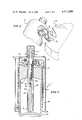
- FIG. 7is a perspective view of a system of this invention being engaged for filling of the inner container.
- a cryogenic breathing system of this inventionincludes a storage container 10 and a portable container 11.
- the storage container 11provides a large supply of liquid oxygen and may be adapted to provide a flow of gaseous oxygen for breathing assistance in the household of a user.
- Portable container 11includes a shoulder strap 12 adapted to carry the container 11 over the shoulder of a user. When carried, the portable container of a user provides a flow of oxygen for breathing while the user is moving about in normal activity.
- the portable containerprovides at its top a visible indication of the level of liquid oxygen present within the container. This visible indication is provided by means of a sight gauge 13 permitting the user to view a liquid level indicating means 14.
- An adjustable valve 15permits the user to adjust the rate of flow of oxygen for his consumption.
- the storage container 10likewise provides visible indication of the level of oxygen within the container.
- This visible indicationlike that of the portable container, includes a sight gauge 16 permitting the user to observe a liquid level indicator 17.
- the storage containerprovides breathing assistance to a user, it includes an adjustable valve 18 to permit the user to control the flow of oxygen for consumption.
- the portable container 11may be supported by the portable container 10 for filling, the support and interconnection being accomplished by a connecting means of the portable container 11 and complementary connecting means of the storage container 10 in a manner to be described.
- FIG. 2 and FIG. 3illustrate the structure of the storage container 10.
- the storage container 10includes a rigid outer casing 19 having a small opening 20 at its top encircled by a flange 21 having a channel 22 adapted to receive an O-ring seal 23.
- the storage container 10also includes an inner container 25 having a small opening 26 at its top. Openings 20 and 26 of the outer casing and inner container, respectively, are connected together by a gas-tight tubular connection 27 forming an evacuable space between the outer casing and inner container.
- Tubular connection 27can be adapted to permit thermal expansion and contraction and other variations of the spacing between the inner container 25 and the outer casing 19.
- this evacuable spaceis filled with multiple layers of thermal insulation including alternate layers of material having poor heat conductivity and layers having high heat reflectivity. Such insulation reduces heat transfer by reducing radiation and conduction of heat through the space between the outer casing and inner container.
- zeolite materialsare provided in the evacuable space to absorb residual molecules remaining after evacuation of the space as is known in the art.
- Containers of this constructionpermit cryogenic fluids, such as liquid oxygen, to be maintained in liquid form for extended periods of time.
- Closure means 29carries within the inner container a coiled tube 30 which may be connected with tube fittings 31 and 32 on the cosure. Closure 29 also carries a withdrawal tube 33 having its opening adjacent the bottom of the inner container and a spring-supported liquid level indicator 34 adjacent the central axis of the closure means 29.
- the coiled tube 30conveniently encircles the liquid level detector means 34 and may be supplemented by a tubular means 35.
- the closure member 29upon its assembly to the storage container, carries, within the inner container 25 through the openings 20 and 26, means to indicate the level of liquid within the inner container, means to permit the addition and withdrawal of liquid oxygen from the inner container, and means to provide thermal energy to the inner container, as will be described.
- the sight gauge 16is threadedly connected to the closure means 29, and the top end 17 of the liquid level indicating means 34 extends within a central bore 36 of the sight gauge 16.
- Also carried by the closure means 29 outside of the outer casingis a connecting means 37 to permit engagement and support of portable container 11 for filling.
- the system of this inventionprovides oxygen for breathing while maintaining the pressure within the storage container and portable container at very low pressure on the order of twenty pounds per square inch above atmospheric pressure.
- the storage container 10is adapted to provide oxygen for breathing, it includes a breathing coil 38 and a vaporizing coil 39 carried concentrically about closure 29 of the outer casing by a plurality of supports 40.
- breathing coil 38is connected at one end to a fitting 41 and a pressure-sensitive valve 42 that is connected with an opening in the closure 29 and thus with the vaporized oxygen at the top of the inner container 25.
- the other end of the breathing coil 38is connected to an adjustable flow control valve 43 (the dial 18 of which is shown in FIG. 1).
- the valve 43provides means to control the flow of oxygen from the inner container to the user for consumption by for example, a plurality of orifices of different areas, permitting different rates of oxygen flow at the preset and controlled operating pressure of the system.
- fittings 44to which the user may connect a humidifier and other breathing apparatus.
- breathing coil 38is also connected through fitting 41 to one side of the coiled tube 30 within the inner container.
- the other side of coiled tube 30is connected to one end of vaporizing coil 39, which is connected at its other end to withdrawal tube 33.
- pressure-sensitive valve 42closes, blocking the flow of gaseous oxygen from the upper portion of the inner container 25 to the breathing coil 38.
- the pressure within the inner container 25then forces liquid oxygen through the withdrawal tube 33 and into vaporizing coil 39 where the heat of the ambient atmosphere vaporizes the liquid oxygen.
- the gaseous oxygenflows through coiled tube 30 near the bottom of the inner container, and out through fitting 41 to breathing coil 38 for consumption.
- the heat carried into the inner container 25 by the heated and vaporized oxygenis transmitted through coil 30 to the liquid oxygen within the inner container, thereby vaporizing the liquid oxygen and increasing the pressure within the inner container until the pressure opens valve 42, permitting consumption of oxygen from the gaseous oxygen at the upper portion of inner container 25.
- a pressure relief valve 45is provided upon the adjustable control 43.
- a pressure relief valve 46is also provided in communication with the upper portion of the inner container to prevent excess pressure from being generated in the inner container in the event of a failure of the tubing, fittings, or valves of the system.
- the closure 29also carries a fitting 37 communicating with the interior of the inner container and including a check valve in order that the storage container may be refilled when the liquid oxygen within its interior is exhausted.
- Fitting 37also provides connecting means for filling the portable container 11, with complementary surfaces 75 to engage connecting means of the portable container, as shown in FIG. 7.
- the liquid level indicating means 34includes an aluminum rod 34a (FIG. 2), which is supported from the gas-tight closure 29 by a spring 34b. Attached to the top of the aluminum rod 34a is a stainless rod 34c. The top portion 17 of the rod 34c extends into a central bore 36 in the sight gauge 16. In the presence of liquid oxygen, the aluminum rod 34a is lifted by spring 34b by virtue of the liquid oxygen it displaces and the top portion 17 of rod 34c will thus provide within sight gauge 17 an indication of the level of liquid oxygen within the inner container 25.
- the means 30 and 35 encircling the liquid level indicating means 34retain it at about the central axis of the inner container 25 regardless of the attitude of the container 10.
- the apparatus at the upper portion of the storage container 10is protected from contact by a dress cover 47.
- the portable container 11 of the systemis constructed in a manner similar to the storage container.
- the containeritself is comprised of an outer casing 50 having an opening 51 and a flange 52 at its top surrounding the opening 51. It also includes an inner container 53 having an opening 54 at its top.
- the openings 51 and 54are connected by a gas-tight tubular connection 55 forming an evacuable space between the inner container 53 and the outer casing 50.
- This evacuable spaceis filled with a multiplicity of layers of material having a low thermal conductivity alternating with layers having high heat reflectivity. Such means inhibits the heat transfer between the inner container and the outer casing.
- the interval between the outer casing and the inner container to be evacuatedcontains zeolite molecular seive materials, as is known in the art, to absorb residual molecules remaining after evacuation, and which have been released from the surfaces of the materials within this interval.
- the portable containeralso includes a plate-like closure 57 attached to the flange at the top of the outer casing of the portable container, for example, by four threaded fasteners.
- the interval between closure 57 and flange 52is rendered leak-free by a seal 58 between the flange and the closure.
- Closure 57carries within the inner container 53 of the portable container a withdrawal tube 59, a spring-supported level indicator 60, and means 61 encircling the liquid level indicating means 60.
- closure 57On the exterior of the outer casing, closure 57 carries fluid connecting means 62 including a check valve (not shown) within it.
- Connecting means 62includes two surfaces 63, one of which is not shown, complementary to mating surfaces 75 in fitting 37 as shown in FIG. 7.
- Also carried outside of the outer casingis a transparent sight gauge 13 having a central bore 64 into which the upper portion 14 of the liquid level detector 60 extends.
- a breathing coil 65 and a warming coil 66are carried outside the outer casing 50 of the portable container 11 in coils wrapped concentrically with the outer casing 50.
- the breathing coil 65is connected at one end with an opening in the closure means 57 communicating with the inner container 53.
- the other end of the breathing coil 65is connected to an adjustable flow control valve 68 (the adjusting knob of which is shown as 15 of FIG. 1).
- the adjustable flow control valve 68provides a plurality of orifices of differing cross sectional areas between the breathing coil and the fitting 69 to which the breathing apparatus of the user is connected, thus providing control of the flow of oxygen to the user.
- a relief valve 70is also connected to the flow control valve 68 to prevent the pressure in the breathing coil from exceeding the preset value of the relief valve.
- one end of the warming coil 66is connected to an opening in closure 57 and is in communication with the interior of the inner container.
- the other end of warming coil 66is fitted with pressure relief valve 71.
- This arrangementprevents the pressure within the inner container from exceeding a preset value and delays the escape of liquid oxygen in the event the portable container is inadvertently set down on its side.
- a vent-to-fill valve 72is provided which opens the inner container 53 of the portable container to atmosphere during filling operations.
- the portable containeris provided with a dress cover 73, as shown in FIG. 5.
- the liquid level indicating means 60includes an aluminum rod 60a, which is supported from the gas-tight closure 57 by a spring 60b. Attached to the top of the aluminum rod 60a is a stainless rod 60c. The top portion 14 of the rod 60c extends into a central bore 64 in the sight gauge 13. In the presence of liquid oxygen, the aluminum rod 60a is lifted by spring 60bby virtue of the liquid oxygen it displaces, and the top portion 14 of rod 60c will thus provide within sight gauge 13 an indication of the level of liquid oxygen within the inner container 53.
- the means 61 encircling the liquid level indicating means 60retains it at about the central axis of the inner container 53 regardless of the attitude of the portable container 11.
- the portable containerIn filling the portable container 11 from storage container 10 as shown in FIG. 7, the portable container is rotated so that its vertical axis is at an angle with respect to horizontal and can be rotated so that its vertical axis is at an inclination approximately 45° displaced from the vertical.
- Connecting means 62 of the portable containeris positioned adjacent the connecting means 37 of storage container 10 and the complementary surfaces 63 of the portable container 11 (which is shown to be a pin) and 75 of the storage container 10 (which is shown to be a shaped slot) are positioned for engagement.
- the portable container 11As the complementary shapes 63 and 75 are engaged and as the portable container 11 is rotated back to the vertical position, the portable container 11 is pulled toward the storage container 10, drawing fitting 62 into fitting 37 so that container 11 is supported by the storage container 10 and locking the portable container 11 to the storage container 10.
- the vent-to-fill valve 72 of the portable container(FIG. 6) is then opened using a special tool, and valve 48 on the storage container 10 is also opened, permitting the pressure within the inner container 25 of the storage container to force liquid oxygen through the connecting means 62 and 37 into the inner container 53 of the portable container. Flow is permitted to continue until the liquid level indicating means 14 of the portable container indicates that the portable container 11 is full of liquid oxygen, and valves 48 and 72 are then closed, completing filling of the portable container.
- a usermay attach, to fitting 69 of flow control valve 68, a breathing mask and by adjustment of the variable flow control valve 68 obtain a controlled flow of oxygen from the portable container as the user moves about.
- the metallic portions of the apparatusare preferably stainless steel.
- the transparent sight gauges and dress coverare preferably a material like that sold by the General Electric Company under its trademark LEXAN.
Landscapes
- Engineering & Computer Science (AREA)
- Mechanical Engineering (AREA)
- General Engineering & Computer Science (AREA)
- Filling Or Discharging Of Gas Storage Vessels (AREA)
Abstract
Description
Claims (19)
Priority Applications (1)
| Application Number | Priority Date | Filing Date | Title |
|---|---|---|---|
| US06/019,450US4211086A (en) | 1977-10-11 | 1979-03-12 | Cryogenic breathing system |
Applications Claiming Priority (2)
| Application Number | Priority Date | Filing Date | Title |
|---|---|---|---|
| US84091677A | 1977-10-11 | 1977-10-11 | |
| US06/019,450US4211086A (en) | 1977-10-11 | 1979-03-12 | Cryogenic breathing system |
Related Parent Applications (1)
| Application Number | Title | Priority Date | Filing Date |
|---|---|---|---|
| US84091677AContinuation | 1977-10-11 | 1977-10-11 |
Publications (1)
| Publication Number | Publication Date |
|---|---|
| US4211086Atrue US4211086A (en) | 1980-07-08 |
Family
ID=26692232
Family Applications (1)
| Application Number | Title | Priority Date | Filing Date |
|---|---|---|---|
| US06/019,450Expired - LifetimeUS4211086A (en) | 1977-10-11 | 1979-03-12 | Cryogenic breathing system |
Country Status (1)
| Country | Link |
|---|---|
| US (1) | US4211086A (en) |
Cited By (66)
| Publication number | Priority date | Publication date | Assignee | Title |
|---|---|---|---|---|
| US4299091A (en)* | 1980-10-08 | 1981-11-10 | Union Carbide Corporation | Portable cryogenic liquid storage-gas supply system |
| US4541276A (en)* | 1983-08-02 | 1985-09-17 | Cryo2 Corporation | Contents gage |
| US4570819A (en)* | 1983-11-30 | 1986-02-18 | Cryo, Corporation | Fill means for cryogenic flasks |
| US4899546A (en)* | 1988-11-02 | 1990-02-13 | Harsco Corporation | Cryogenic liquid container |
| EP0356546A1 (en)* | 1986-07-30 | 1990-03-07 | Larry Hohol | Cryogenic withdrawal apparatus and method |
| WO1993004647A1 (en)* | 1991-09-06 | 1993-03-18 | Cryomedical Sciences, Inc. | Cryosurgical instrument with vent holes and method |
| US5321955A (en)* | 1992-12-22 | 1994-06-21 | Leonard Rex D | Cryogenic shipping system |
| US5357758A (en)* | 1993-06-01 | 1994-10-25 | Andonian Martin D | All position cryogenic liquefied-gas container |
| EP0657182A3 (en)* | 1993-11-16 | 1995-09-13 | Invacare Corp | Method and apparatus for dispensing respiratory gases. |
| US5520682A (en)* | 1991-09-06 | 1996-05-28 | Cryomedical Sciences, Inc. | Cryosurgical instrument with vent means and method using same |
| US5558139A (en)* | 1995-02-13 | 1996-09-24 | Essex Cryogenics Of Missouri | Liquid oxygen system |
| US5614294A (en)* | 1994-11-30 | 1997-03-25 | United Technologies Corporation | Coating for minimizing thermal gradients in an article |
| WO1998058219A1 (en)* | 1997-06-16 | 1998-12-23 | Sequal Technologies, Inc. | Methods and apparatus to generate liquid ambulatory oxygen from an oxygen concentrator |
| US5893275A (en)* | 1997-09-04 | 1999-04-13 | In-X Corporation | Compact small volume liquid oxygen production system |
| US5906100A (en)* | 1992-10-06 | 1999-05-25 | Oceaneering International Inc. | Dewar for storing and delivering liquid cryogen |
| US6012453A (en)* | 1995-04-20 | 2000-01-11 | Figgie Inernational Inc. | Apparatus for withdrawal of liquid from a container and method |
| US6089226A (en)* | 1996-11-22 | 2000-07-18 | Aerospace Design & Development, Inc. | Self contained, cryogenic mixed gas single phase storage and delivery |
| US6138670A (en)* | 1994-08-26 | 2000-10-31 | Compagnie Maritime D' Expertises-Comex | Process and installation for underwater diving employing a breathing mixture containing hydrogen |
| WO2001031254A1 (en)* | 1999-10-29 | 2001-05-03 | L'air Liquide, Societe Anonyme Pour L'etude Et L'exploitation Des Procedes Georges Claude | Transportable device for storing and supplying cryogenic fluid, especially medical oxygen |
| FR2800438A1 (en)* | 1999-10-29 | 2001-05-04 | Air Liquide | Transportable apparatus for storing/supplying acryogenic fluid, esp oxygen for medical purposes, has handling collar with condensate collector |
| WO2001033135A1 (en)* | 1999-10-29 | 2001-05-10 | Mallinckrodt Inc. | High efficiency liquid oxygen storage and delivery system |
| FR2801371A1 (en)* | 1999-11-23 | 2001-05-25 | Air Liquide | Transportable apparatus for storing/supplying acryogenic fluid, esp oxygen for medical purposes, has handling collar with condensate collector |
| US6257000B1 (en)* | 2000-03-22 | 2001-07-10 | Luping Wang | Fluid storage and dispensing system featuring interiorly disposed and exteriorly adjustable regulator for high flow dispensing of gas |
| WO2002012779A1 (en)* | 2000-08-10 | 2002-02-14 | Advanced Technology Materials, Inc. | Fluid storage and dispensing system featuring externally adjustable regulator assembly for high flow dispensing |
| US6382208B2 (en) | 1998-11-02 | 2002-05-07 | Board Of Regents University Of Nebraska | System for controlling the internal temperature of a respirator |
| US6393846B1 (en) | 1999-10-29 | 2002-05-28 | Mallinckrodt Inc. | Manifold for use in a portable liquid oxygen unit |
| US6575159B1 (en) | 1999-10-29 | 2003-06-10 | Mallinckrodt Inc. | Portable liquid oxygen unit with multiple operational orientations |
| US6742517B1 (en) | 1999-10-29 | 2004-06-01 | Mallinckrodt, Inc. | High efficiency liquid oxygen system |
| US20050011583A1 (en)* | 2003-07-16 | 2005-01-20 | Gale Peter P. | Portable, cryogenic gas delivery apparatus |
| US20050274142A1 (en)* | 2004-06-14 | 2005-12-15 | Corey John A | Cryogenically producing oxygen-enriched liquid and/or gaseous oxygen from atmospheric air |
| US20060000223A1 (en)* | 2004-07-01 | 2006-01-05 | In-X Corporation | Desiccant cartridge |
| US20060086099A1 (en)* | 2004-10-26 | 2006-04-27 | In-X Corporation | Liquefying and storing a gas |
| FR2888120A1 (en)* | 2005-07-07 | 2007-01-12 | Cryo Diffusion S A Sa | Cryogenic fluid supply and storage device for respiration, has dampening junction situated between main coil and flow meter valve for receiving derivation with pressure drop element constituted by channel opening in blind and rigid cavity |
| US20070144590A1 (en)* | 2005-12-22 | 2007-06-28 | Simmons Stephen T | Fluid control device |
| EP1890074A1 (en)* | 2006-08-16 | 2008-02-20 | L'air Liquide, Societe Anonyme Pour L'etude Et L'exploitation Des Procedes Georges Claude | Portable device for oxygen storage and delivery |
| EP1890073A1 (en)* | 2006-08-16 | 2008-02-20 | L'Air Liquide S. A. à Directoire et Conseil de Surveillance pour l'Etude et l'Exploitation des Procédés Georges Claude | Portable device for oxygen storage and delivery |
| US20080178610A1 (en)* | 2007-01-30 | 2008-07-31 | Douglas Whitcher | Portable Liquid Oxygen Storage Unit |
| US20080277399A1 (en)* | 2007-04-20 | 2008-11-13 | Ricky Dean Burns | System and Method for Filling a Portable Liquified Gas Storage/Delivery System |
| US20100059694A1 (en)* | 2002-06-10 | 2010-03-11 | Advanced Technology Materials, Inc. | Pressure-based gas delivery system and method for reducing risks associated with storage and delivery of high pressure gases |
| US20100071693A1 (en)* | 2008-08-22 | 2010-03-25 | Breathe Technologies | Methods and devices for providing mechanical ventilation with an open airway interface |
| US20100212330A1 (en)* | 2005-07-29 | 2010-08-26 | Ric Investments, Llc | Portable liquid oxygen delivery system |
| US8136527B2 (en) | 2003-08-18 | 2012-03-20 | Breathe Technologies, Inc. | Method and device for non-invasive ventilation with nasal interface |
| US8381729B2 (en) | 2003-06-18 | 2013-02-26 | Breathe Technologies, Inc. | Methods and devices for minimally invasive respiratory support |
| US8402965B1 (en) | 2009-01-30 | 2013-03-26 | Essex Cryogenics Of Missouri, Inc. | Mass oxygen distribution system |
| CN103007400A (en)* | 2012-06-14 | 2013-04-03 | 赵军政 | Micro first-aid oxygen inhaler |
| US8418694B2 (en) | 2003-08-11 | 2013-04-16 | Breathe Technologies, Inc. | Systems, methods and apparatus for respiratory support of a patient |
| US8567399B2 (en) | 2007-09-26 | 2013-10-29 | Breathe Technologies, Inc. | Methods and devices for providing inspiratory and expiratory flow relief during ventilation therapy |
| WO2010033373A3 (en)* | 2008-09-18 | 2013-12-27 | Nellcor Puritan Bennett Llc | Compact cryogenic cooling chamber for oxygen liquefaction system |
| US8770193B2 (en) | 2008-04-18 | 2014-07-08 | Breathe Technologies, Inc. | Methods and devices for sensing respiration and controlling ventilator functions |
| US8776793B2 (en) | 2008-04-18 | 2014-07-15 | Breathe Technologies, Inc. | Methods and devices for sensing respiration and controlling ventilator functions |
| WO2014152505A1 (en)* | 2013-03-15 | 2014-09-25 | Worthington Cylinders Corporation | Cryogenic fluid cylinder |
| US8925545B2 (en) | 2004-02-04 | 2015-01-06 | Breathe Technologies, Inc. | Methods and devices for treating sleep apnea |
| US8939152B2 (en) | 2010-09-30 | 2015-01-27 | Breathe Technologies, Inc. | Methods, systems and devices for humidifying a respiratory tract |
| US8955518B2 (en) | 2003-06-18 | 2015-02-17 | Breathe Technologies, Inc. | Methods, systems and devices for improving ventilation in a lung area |
| US8985099B2 (en) | 2006-05-18 | 2015-03-24 | Breathe Technologies, Inc. | Tracheostoma spacer, tracheotomy method, and device for inserting a tracheostoma spacer |
| JP2015117752A (en)* | 2013-12-18 | 2015-06-25 | 大陽日酸株式会社 | Device for transferring and filling low-temperature liquefied gas |
| US9132250B2 (en) | 2009-09-03 | 2015-09-15 | Breathe Technologies, Inc. | Methods, systems and devices for non-invasive ventilation including a non-sealing ventilation interface with an entrainment port and/or pressure feature |
| US9180270B2 (en) | 2009-04-02 | 2015-11-10 | Breathe Technologies, Inc. | Methods, systems and devices for non-invasive open ventilation with gas delivery nozzles within an outer tube |
| US20160003525A1 (en)* | 2009-09-29 | 2016-01-07 | Koninklijke Philips N.V. | System and method for liquefying a fluid and storing the liquefied fluid |
| US9962512B2 (en) | 2009-04-02 | 2018-05-08 | Breathe Technologies, Inc. | Methods, systems and devices for non-invasive ventilation including a non-sealing ventilation interface with a free space nozzle feature |
| US10058668B2 (en) | 2007-05-18 | 2018-08-28 | Breathe Technologies, Inc. | Methods and devices for sensing respiration and providing ventilation therapy |
| US10099028B2 (en) | 2010-08-16 | 2018-10-16 | Breathe Technologies, Inc. | Methods, systems and devices using LOX to provide ventilatory support |
| US10252020B2 (en) | 2008-10-01 | 2019-04-09 | Breathe Technologies, Inc. | Ventilator with biofeedback monitoring and control for improving patient activity and health |
| US10792449B2 (en) | 2017-10-03 | 2020-10-06 | Breathe Technologies, Inc. | Patient interface with integrated jet pump |
| CN113503464A (en)* | 2021-06-21 | 2021-10-15 | 西藏友氧健康科技有限公司 | Novel liquid oxygen supply device |
| US11154672B2 (en) | 2009-09-03 | 2021-10-26 | Breathe Technologies, Inc. | Methods, systems and devices for non-invasive ventilation including a non-sealing ventilation interface with an entrainment port and/or pressure feature |
Citations (5)
| Publication number | Priority date | Publication date | Assignee | Title |
|---|---|---|---|---|
| US3199303A (en)* | 1963-05-09 | 1965-08-10 | Union Carbide Corp | Oxygen therapy system |
| US3797262A (en)* | 1972-12-01 | 1974-03-19 | Union Carbide Corp | Cryogenic fluid supply system |
| US3941124A (en)* | 1969-01-21 | 1976-03-02 | Rodewald Newell C | Recirculating breathing apparatus and method |
| US3946572A (en)* | 1974-09-26 | 1976-03-30 | Parker-Hannifin Corporation | Apparatus for transferring cryogenic liquid from one dewar to another |
| US4018582A (en)* | 1976-03-29 | 1977-04-19 | The Bendix Corporation | Vent tube means for a cryogenic container |
- 1979
- 1979-03-12USUS06/019,450patent/US4211086A/ennot_activeExpired - Lifetime
Patent Citations (5)
| Publication number | Priority date | Publication date | Assignee | Title |
|---|---|---|---|---|
| US3199303A (en)* | 1963-05-09 | 1965-08-10 | Union Carbide Corp | Oxygen therapy system |
| US3941124A (en)* | 1969-01-21 | 1976-03-02 | Rodewald Newell C | Recirculating breathing apparatus and method |
| US3797262A (en)* | 1972-12-01 | 1974-03-19 | Union Carbide Corp | Cryogenic fluid supply system |
| US3946572A (en)* | 1974-09-26 | 1976-03-30 | Parker-Hannifin Corporation | Apparatus for transferring cryogenic liquid from one dewar to another |
| US4018582A (en)* | 1976-03-29 | 1977-04-19 | The Bendix Corporation | Vent tube means for a cryogenic container |
Cited By (123)
| Publication number | Priority date | Publication date | Assignee | Title |
|---|---|---|---|---|
| US4299091A (en)* | 1980-10-08 | 1981-11-10 | Union Carbide Corporation | Portable cryogenic liquid storage-gas supply system |
| US4541276A (en)* | 1983-08-02 | 1985-09-17 | Cryo2 Corporation | Contents gage |
| US4570819A (en)* | 1983-11-30 | 1986-02-18 | Cryo, Corporation | Fill means for cryogenic flasks |
| EP0356546A1 (en)* | 1986-07-30 | 1990-03-07 | Larry Hohol | Cryogenic withdrawal apparatus and method |
| US4899546A (en)* | 1988-11-02 | 1990-02-13 | Harsco Corporation | Cryogenic liquid container |
| US5254116A (en)* | 1991-09-06 | 1993-10-19 | Cryomedical Sciences, Inc. | Cryosurgical instrument with vent holes and method using same |
| US5520682A (en)* | 1991-09-06 | 1996-05-28 | Cryomedical Sciences, Inc. | Cryosurgical instrument with vent means and method using same |
| WO1993004647A1 (en)* | 1991-09-06 | 1993-03-18 | Cryomedical Sciences, Inc. | Cryosurgical instrument with vent holes and method |
| US6513521B1 (en) | 1992-05-07 | 2003-02-04 | Aerospace Design & Development, Inc. | Cryogenic mixed gas single phase storage and delivery |
| US5906100A (en)* | 1992-10-06 | 1999-05-25 | Oceaneering International Inc. | Dewar for storing and delivering liquid cryogen |
| US5321955A (en)* | 1992-12-22 | 1994-06-21 | Leonard Rex D | Cryogenic shipping system |
| US5357758A (en)* | 1993-06-01 | 1994-10-25 | Andonian Martin D | All position cryogenic liquefied-gas container |
| EP0657182A3 (en)* | 1993-11-16 | 1995-09-13 | Invacare Corp | Method and apparatus for dispensing respiratory gases. |
| US6138670A (en)* | 1994-08-26 | 2000-10-31 | Compagnie Maritime D' Expertises-Comex | Process and installation for underwater diving employing a breathing mixture containing hydrogen |
| US5614294A (en)* | 1994-11-30 | 1997-03-25 | United Technologies Corporation | Coating for minimizing thermal gradients in an article |
| US5558139A (en)* | 1995-02-13 | 1996-09-24 | Essex Cryogenics Of Missouri | Liquid oxygen system |
| US6012453A (en)* | 1995-04-20 | 2000-01-11 | Figgie Inernational Inc. | Apparatus for withdrawal of liquid from a container and method |
| US6089226A (en)* | 1996-11-22 | 2000-07-18 | Aerospace Design & Development, Inc. | Self contained, cryogenic mixed gas single phase storage and delivery |
| US5979440A (en)* | 1997-06-16 | 1999-11-09 | Sequal Technologies, Inc. | Methods and apparatus to generate liquid ambulatory oxygen from an oxygen concentrator |
| WO1998058219A1 (en)* | 1997-06-16 | 1998-12-23 | Sequal Technologies, Inc. | Methods and apparatus to generate liquid ambulatory oxygen from an oxygen concentrator |
| USRE43398E1 (en)* | 1997-06-16 | 2012-05-22 | Respironics, Inc. | Methods and apparatus to generate liquid ambulatory oxygen from an oxygen concentrator |
| US6698423B1 (en)* | 1997-06-16 | 2004-03-02 | Sequal Technologies, Inc. | Methods and apparatus to generate liquid ambulatory oxygen from an oxygen concentrator |
| US6681764B1 (en)* | 1997-06-16 | 2004-01-27 | Sequal Technologies, Inc. | Methods and apparatus to generate liquid ambulatory oxygen from an oxygen concentrator |
| US5893275A (en)* | 1997-09-04 | 1999-04-13 | In-X Corporation | Compact small volume liquid oxygen production system |
| US6382208B2 (en) | 1998-11-02 | 2002-05-07 | Board Of Regents University Of Nebraska | System for controlling the internal temperature of a respirator |
| US20050247308A1 (en)* | 1999-10-29 | 2005-11-10 | Mallinckrodt Inc. | High efficiency liquid oxygen system |
| AU784005B2 (en)* | 1999-10-29 | 2006-01-12 | Chart Industries Luxembourg S.A.R.L. | High efficiency liquid oxygen storage and delivery system |
| US20080066471A1 (en)* | 1999-10-29 | 2008-03-20 | Frye Mark R | Portable liquid oxygen unit with multiple operational orientations |
| FR2800438A1 (en)* | 1999-10-29 | 2001-05-04 | Air Liquide | Transportable apparatus for storing/supplying acryogenic fluid, esp oxygen for medical purposes, has handling collar with condensate collector |
| US6279326B1 (en)* | 1999-10-29 | 2001-08-28 | L'air Liquide, Societe Anonyme Pour L'etude Et L'exploitation Des Procedes Georges Claude | Transportable device for storing and supplying cryogenic fluid, more particularly medical oxygen |
| US6393846B1 (en) | 1999-10-29 | 2002-05-28 | Mallinckrodt Inc. | Manifold for use in a portable liquid oxygen unit |
| US7490605B2 (en)* | 1999-10-29 | 2009-02-17 | Mallinckrodt, Inc. | High efficiency liquid oxygen system |
| JP2003512911A (en)* | 1999-10-29 | 2003-04-08 | マリンクロッド・インコーポレイテッド | High performance liquid oxygen storage and delivery system |
| US6575159B1 (en) | 1999-10-29 | 2003-06-10 | Mallinckrodt Inc. | Portable liquid oxygen unit with multiple operational orientations |
| US7296569B2 (en)* | 1999-10-29 | 2007-11-20 | Mallinckrodt, Inc. | Portable liquid oxygen unit with multiple operational orientations |
| WO2001033135A1 (en)* | 1999-10-29 | 2001-05-10 | Mallinckrodt Inc. | High efficiency liquid oxygen storage and delivery system |
| US6742517B1 (en) | 1999-10-29 | 2004-06-01 | Mallinckrodt, Inc. | High efficiency liquid oxygen system |
| US6843247B2 (en) | 1999-10-29 | 2005-01-18 | Mallinckrodt Inc. | Portable liquid oxygen unit with multiple operational orientations |
| US7766009B2 (en) | 1999-10-29 | 2010-08-03 | Caire Inc. | Portable liquid oxygen unit with multiple operational orientations |
| US20050098174A1 (en)* | 1999-10-29 | 2005-05-12 | Mallinckrodt Inc. | Portable liquid oxygen unit with multiple operational orientations |
| WO2001031254A1 (en)* | 1999-10-29 | 2001-05-03 | L'air Liquide, Societe Anonyme Pour L'etude Et L'exploitation Des Procedes Georges Claude | Transportable device for storing and supplying cryogenic fluid, especially medical oxygen |
| FR2801371A1 (en)* | 1999-11-23 | 2001-05-25 | Air Liquide | Transportable apparatus for storing/supplying acryogenic fluid, esp oxygen for medical purposes, has handling collar with condensate collector |
| WO2001071242A1 (en)* | 2000-03-22 | 2001-09-27 | Advanced Technology Materials, Inc. | Dispensing system with interiorly disposed and exteriorly adjustable regulator assembly |
| US6257000B1 (en)* | 2000-03-22 | 2001-07-10 | Luping Wang | Fluid storage and dispensing system featuring interiorly disposed and exteriorly adjustable regulator for high flow dispensing of gas |
| US6360546B1 (en)* | 2000-08-10 | 2002-03-26 | Advanced Technology Materials, Inc. | Fluid storage and dispensing system featuring externally adjustable regulator assembly for high flow dispensing |
| WO2002012779A1 (en)* | 2000-08-10 | 2002-02-14 | Advanced Technology Materials, Inc. | Fluid storage and dispensing system featuring externally adjustable regulator assembly for high flow dispensing |
| US7798168B2 (en) | 2002-06-10 | 2010-09-21 | Advanced Technology Materials, Inc. | Pressure-based gas delivery system and method for reducing risks associated with storage and delivery of high pressure gases |
| US20100059694A1 (en)* | 2002-06-10 | 2010-03-11 | Advanced Technology Materials, Inc. | Pressure-based gas delivery system and method for reducing risks associated with storage and delivery of high pressure gases |
| US8381729B2 (en) | 2003-06-18 | 2013-02-26 | Breathe Technologies, Inc. | Methods and devices for minimally invasive respiratory support |
| US8955518B2 (en) | 2003-06-18 | 2015-02-17 | Breathe Technologies, Inc. | Methods, systems and devices for improving ventilation in a lung area |
| US20050011583A1 (en)* | 2003-07-16 | 2005-01-20 | Gale Peter P. | Portable, cryogenic gas delivery apparatus |
| US6910510B2 (en)* | 2003-07-16 | 2005-06-28 | Precision Medical, Inc. | Portable, cryogenic gas delivery apparatus |
| US8418694B2 (en) | 2003-08-11 | 2013-04-16 | Breathe Technologies, Inc. | Systems, methods and apparatus for respiratory support of a patient |
| US8573219B2 (en) | 2003-08-18 | 2013-11-05 | Breathe Technologies, Inc. | Method and device for non-invasive ventilation with nasal interface |
| US8136527B2 (en) | 2003-08-18 | 2012-03-20 | Breathe Technologies, Inc. | Method and device for non-invasive ventilation with nasal interface |
| US8925545B2 (en) | 2004-02-04 | 2015-01-06 | Breathe Technologies, Inc. | Methods and devices for treating sleep apnea |
| US20050274142A1 (en)* | 2004-06-14 | 2005-12-15 | Corey John A | Cryogenically producing oxygen-enriched liquid and/or gaseous oxygen from atmospheric air |
| US20060000223A1 (en)* | 2004-07-01 | 2006-01-05 | In-X Corporation | Desiccant cartridge |
| US7913497B2 (en) | 2004-07-01 | 2011-03-29 | Respironics, Inc. | Desiccant cartridge |
| US20060086099A1 (en)* | 2004-10-26 | 2006-04-27 | In-X Corporation | Liquefying and storing a gas |
| AU2005299287B2 (en)* | 2004-10-26 | 2010-05-13 | Respironics In-X, Inc. | Liquefying and storing a gas |
| US7318327B2 (en) | 2004-10-26 | 2008-01-15 | Respironics In-X, Inc. | Liquefying and storing a gas |
| AU2008243145B2 (en)* | 2004-10-26 | 2011-12-22 | Respironics In-X, Inc | Liquefying and storing a gas |
| US7555916B2 (en) | 2004-10-26 | 2009-07-07 | Respironics In-X, Inc. | Liquefying and storing a gas |
| US20060086102A1 (en)* | 2004-10-26 | 2006-04-27 | In-X Corporation | Liquefying and storing a gas |
| EP1805451A4 (en)* | 2004-10-26 | 2011-08-31 | Respironics Inc | Liquefying and storing a gas |
| WO2006047664A3 (en)* | 2004-10-26 | 2007-03-22 | Respironics In X Inc | Liquefying and storing a gas |
| US20080120982A1 (en)* | 2004-10-26 | 2008-05-29 | Respironics In-X, Inc. | Liquefying and storing a gas |
| US7213400B2 (en) | 2004-10-26 | 2007-05-08 | Respironics In-X, Inc. | Liquefying and storing a gas |
| FR2888120A1 (en)* | 2005-07-07 | 2007-01-12 | Cryo Diffusion S A Sa | Cryogenic fluid supply and storage device for respiration, has dampening junction situated between main coil and flow meter valve for receiving derivation with pressure drop element constituted by channel opening in blind and rigid cavity |
| US20100212330A1 (en)* | 2005-07-29 | 2010-08-26 | Ric Investments, Llc | Portable liquid oxygen delivery system |
| US8256415B2 (en) | 2005-07-29 | 2012-09-04 | Ric Investments, Llc | Portable liquid oxygen delivery system |
| EP1909922A4 (en)* | 2005-07-29 | 2011-09-21 | Ric Investments Llc | Portable liquid oxygen delivery system |
| US20070144590A1 (en)* | 2005-12-22 | 2007-06-28 | Simmons Stephen T | Fluid control device |
| US8985099B2 (en) | 2006-05-18 | 2015-03-24 | Breathe Technologies, Inc. | Tracheostoma spacer, tracheotomy method, and device for inserting a tracheostoma spacer |
| FR2904997A1 (en)* | 2006-08-16 | 2008-02-22 | Air Liquide | TRANSPORTABLE STORAGE AND OXYGEN DELIVERY DEVICE |
| EP1890073A1 (en)* | 2006-08-16 | 2008-02-20 | L'Air Liquide S. A. à Directoire et Conseil de Surveillance pour l'Etude et l'Exploitation des Procédés Georges Claude | Portable device for oxygen storage and delivery |
| EP1890074A1 (en)* | 2006-08-16 | 2008-02-20 | L'air Liquide, Societe Anonyme Pour L'etude Et L'exploitation Des Procedes Georges Claude | Portable device for oxygen storage and delivery |
| US20080042382A1 (en)* | 2006-08-16 | 2008-02-21 | Philippe Dodier | Transportable device for storing and delivering oxygen |
| FR2904998A1 (en)* | 2006-08-16 | 2008-02-22 | Air Liquide | TRANSPORTABLE STORAGE AND OXYGEN DELIVERY DEVICE |
| US20080178610A1 (en)* | 2007-01-30 | 2008-07-31 | Douglas Whitcher | Portable Liquid Oxygen Storage Unit |
| US8468839B2 (en)* | 2007-01-30 | 2013-06-25 | Ric Investments, Llc | Portable liquid oxygen storage unit |
| CN101594910B (en)* | 2007-01-30 | 2012-08-08 | Ric投资有限责任公司 | Portable liquid oxygen storage unit |
| US8915268B2 (en) | 2007-04-20 | 2014-12-23 | Ric Investments, Llc | System and method for filling a portable liquefied gas storage/delivery system |
| US8156972B2 (en)* | 2007-04-20 | 2012-04-17 | Ric Investments, Llc | System and method for filling a portable liquified gas storage/delivery system |
| US20080277399A1 (en)* | 2007-04-20 | 2008-11-13 | Ricky Dean Burns | System and Method for Filling a Portable Liquified Gas Storage/Delivery System |
| US10058668B2 (en) | 2007-05-18 | 2018-08-28 | Breathe Technologies, Inc. | Methods and devices for sensing respiration and providing ventilation therapy |
| US8567399B2 (en) | 2007-09-26 | 2013-10-29 | Breathe Technologies, Inc. | Methods and devices for providing inspiratory and expiratory flow relief during ventilation therapy |
| US8770193B2 (en) | 2008-04-18 | 2014-07-08 | Breathe Technologies, Inc. | Methods and devices for sensing respiration and controlling ventilator functions |
| US8776793B2 (en) | 2008-04-18 | 2014-07-15 | Breathe Technologies, Inc. | Methods and devices for sensing respiration and controlling ventilator functions |
| US8677999B2 (en) | 2008-08-22 | 2014-03-25 | Breathe Technologies, Inc. | Methods and devices for providing mechanical ventilation with an open airway interface |
| US20100071693A1 (en)* | 2008-08-22 | 2010-03-25 | Breathe Technologies | Methods and devices for providing mechanical ventilation with an open airway interface |
| WO2010033373A3 (en)* | 2008-09-18 | 2013-12-27 | Nellcor Puritan Bennett Llc | Compact cryogenic cooling chamber for oxygen liquefaction system |
| US10252020B2 (en) | 2008-10-01 | 2019-04-09 | Breathe Technologies, Inc. | Ventilator with biofeedback monitoring and control for improving patient activity and health |
| US8402965B1 (en) | 2009-01-30 | 2013-03-26 | Essex Cryogenics Of Missouri, Inc. | Mass oxygen distribution system |
| US10695519B2 (en) | 2009-04-02 | 2020-06-30 | Breathe Technologies, Inc. | Methods, systems and devices for non-invasive open ventilation with gas delivery nozzles within nasal pillows |
| US10232136B2 (en) | 2009-04-02 | 2019-03-19 | Breathe Technologies, Inc. | Methods, systems and devices for non-invasive open ventilation for treating airway obstructions |
| US12364835B2 (en) | 2009-04-02 | 2025-07-22 | Breathe Technologies, Inc. | Methods, systems and devices for non-invasive ventilation with gas delivery nozzles in free space |
| US9180270B2 (en) | 2009-04-02 | 2015-11-10 | Breathe Technologies, Inc. | Methods, systems and devices for non-invasive open ventilation with gas delivery nozzles within an outer tube |
| US9227034B2 (en) | 2009-04-02 | 2016-01-05 | Beathe Technologies, Inc. | Methods, systems and devices for non-invasive open ventilation for treating airway obstructions |
| US12161807B2 (en) | 2009-04-02 | 2024-12-10 | Breathe Technologies, Inc. | Methods, systems and devices for non-invasive open ventilation with gas delivery nozzles within nasal pillows |
| US11896766B2 (en) | 2009-04-02 | 2024-02-13 | Breathe Technologies, Inc. | Methods, systems and devices for non-invasive ventilation with gas delivery nozzles in free space |
| US9675774B2 (en) | 2009-04-02 | 2017-06-13 | Breathe Technologies, Inc. | Methods, systems and devices for non-invasive open ventilation with gas delivery nozzles in free space |
| US11707591B2 (en) | 2009-04-02 | 2023-07-25 | Breathe Technologies, Inc. | Methods, systems and devices for non-invasive open ventilation with gas delivery nozzles with an outer tube |
| US9962512B2 (en) | 2009-04-02 | 2018-05-08 | Breathe Technologies, Inc. | Methods, systems and devices for non-invasive ventilation including a non-sealing ventilation interface with a free space nozzle feature |
| US10046133B2 (en) | 2009-04-02 | 2018-08-14 | Breathe Technologies, Inc. | Methods, systems and devices for non-invasive open ventilation for providing ventilation support |
| US11103667B2 (en) | 2009-04-02 | 2021-08-31 | Breathe Technologies, Inc. | Methods, systems and devices for non-invasive ventilation with gas delivery nozzles in free space |
| US10709864B2 (en) | 2009-04-02 | 2020-07-14 | Breathe Technologies, Inc. | Methods, systems and devices for non-invasive open ventilation with gas delivery nozzles with an outer tube |
| US11154672B2 (en) | 2009-09-03 | 2021-10-26 | Breathe Technologies, Inc. | Methods, systems and devices for non-invasive ventilation including a non-sealing ventilation interface with an entrainment port and/or pressure feature |
| US9132250B2 (en) | 2009-09-03 | 2015-09-15 | Breathe Technologies, Inc. | Methods, systems and devices for non-invasive ventilation including a non-sealing ventilation interface with an entrainment port and/or pressure feature |
| US10265486B2 (en) | 2009-09-03 | 2019-04-23 | Breathe Technologies, Inc. | Methods, systems and devices for non-invasive ventilation including a non-sealing ventilation interface with an entrainment port and/or pressure feature |
| US12048813B2 (en) | 2009-09-03 | 2024-07-30 | Breathe Technologies, Inc. | Methods, systems and devices for non-invasive ventilation including a non-sealing ventilation interface with an entrainment port and/or pressure feature |
| US20160003525A1 (en)* | 2009-09-29 | 2016-01-07 | Koninklijke Philips N.V. | System and method for liquefying a fluid and storing the liquefied fluid |
| US9841228B2 (en)* | 2009-09-29 | 2017-12-12 | Koninklijke Philips N.V. | System and method for liquefying a fluid and storing the liquefied fluid |
| US10099028B2 (en) | 2010-08-16 | 2018-10-16 | Breathe Technologies, Inc. | Methods, systems and devices using LOX to provide ventilatory support |
| US8939152B2 (en) | 2010-09-30 | 2015-01-27 | Breathe Technologies, Inc. | Methods, systems and devices for humidifying a respiratory tract |
| US9358358B2 (en) | 2010-09-30 | 2016-06-07 | Breathe Technologies, Inc. | Methods, systems and devices for humidifying a respiratory tract |
| CN103007400A (en)* | 2012-06-14 | 2013-04-03 | 赵军政 | Micro first-aid oxygen inhaler |
| WO2014152505A1 (en)* | 2013-03-15 | 2014-09-25 | Worthington Cylinders Corporation | Cryogenic fluid cylinder |
| JP2015117752A (en)* | 2013-12-18 | 2015-06-25 | 大陽日酸株式会社 | Device for transferring and filling low-temperature liquefied gas |
| US12017002B2 (en) | 2017-10-03 | 2024-06-25 | Breathe Technologies, Inc. | Patient interface with integrated jet pump |
| US10792449B2 (en) | 2017-10-03 | 2020-10-06 | Breathe Technologies, Inc. | Patient interface with integrated jet pump |
| CN113503464A (en)* | 2021-06-21 | 2021-10-15 | 西藏友氧健康科技有限公司 | Novel liquid oxygen supply device |
Similar Documents
| Publication | Publication Date | Title |
|---|---|---|
| US4211086A (en) | Cryogenic breathing system | |
| US5357758A (en) | All position cryogenic liquefied-gas container | |
| US3199303A (en) | Oxygen therapy system | |
| US2970452A (en) | Method and apparatus for supplying liquefied gas | |
| US3827246A (en) | Pressure control system for cryogenic fluids | |
| AU2005299287B2 (en) | Liquefying and storing a gas | |
| US7721733B2 (en) | Portable liquid oxygen delivery system | |
| CA2037810C (en) | Cryogenic storage container | |
| US5438837A (en) | Apparatus for storing and delivering liquid cryogen and apparatus and process for filling same | |
| US5488831A (en) | Liquid cryogen withdrawal device | |
| US4854128A (en) | Cryogen supply system | |
| US6513521B1 (en) | Cryogenic mixed gas single phase storage and delivery | |
| US4116199A (en) | Cryosurgical instrument reservoir | |
| US3797262A (en) | Cryogenic fluid supply system | |
| US3696627A (en) | Liquid cryogen transfer system | |
| US5582016A (en) | Conditioning and loading apparatus and method for gas storage at cryogenic temperature and supercritical pressure | |
| WO1997010025A1 (en) | Personal oxygen dispenser | |
| US3572048A (en) | Ominpositional cryogenic underwater breathind apparatus | |
| AU612225B2 (en) | Method and apparatus for storing cryogenic fluids | |
| US3864928A (en) | All-attitude cryogenic vapor vent system | |
| WO1997003317A1 (en) | Cryogenic liquid delivery system | |
| CA1142425A (en) | Cryogenic liquid transfer termination apparatus | |
| US4299091A (en) | Portable cryogenic liquid storage-gas supply system | |
| US4570819A (en) | Fill means for cryogenic flasks | |
| US2434956A (en) | Liquid oxygen "walkaround" unit |
Legal Events
| Date | Code | Title | Description |
|---|---|---|---|
| AS | Assignment | Owner name:CRYOGENIC ASSOCIATES 6565 COFFMAN ROAD,INDIANAPOLI Free format text:ASSIGNMENT OF ASSIGNORS INTEREST.;ASSIGNOR:BEATRICE COMPANIES,INC.;REEL/FRAME:004352/0190 Effective date:19850121 | |
| AS | Assignment | Owner name:NALGE COMPANY, 75 PANORAMA CREEK DRIVE, ROCHESTER, Free format text:ASSIGNMENT OF ASSIGNORS INTEREST.;ASSIGNOR:SYBRON CORPORATION, A CORP. OF NY;REEL/FRAME:004607/0137 Effective date:19860731 Owner name:NALGE COMPANY, 75 PANORAMA CREEK DRIVE, ROCHESTER, Free format text:ASSIGNMENT OF ASSIGNORS INTEREST;ASSIGNOR:SYBRON CORPORATION, A CORP. OF NY;REEL/FRAME:004607/0137 Effective date:19860731 | |
| AS | Assignment | Owner name:MINNESOTA VALLEY ENGINEERING, INC., 407 SEVENTH ST Free format text:ASSIGNMENT OF ASSIGNORS INTEREST.;ASSIGNOR:NALGE COMPANY, A DE. CORP.;REEL/FRAME:004636/0646 Effective date:19861001 Owner name:MINNESOTA VALLEY ENGINEERING, INC., A DE. CORP., M Free format text:ASSIGNMENT OF ASSIGNORS INTEREST;ASSIGNOR:NALGE COMPANY, A DE. CORP.;REEL/FRAME:004636/0646 Effective date:19861001 | |
| RF | Reissue application filed | Effective date:19930621 | |
| AS | Assignment | Owner name:JPMORGAN CHASE BANK (FORMERLY KNOWN AS THE CHASE B Free format text:SECURITY AGREEMENT;ASSIGNOR:CHART INDUSTRIES, INC;REEL/FRAME:012590/0215 Effective date:19990412 | |
| AS | Assignment | Owner name:CHART INDUSTRIES, INC., OHIO Free format text:TERMINATION AND RELEASE OF SECURITY INTEREST;ASSIGNOR:JPMORGAN CHASE BANK, N.A. (F.K.A. THE CHASE MANHATTAN BANK);REEL/FRAME:016686/0482 Effective date:20051017 |