US4209040A - Seal means for high pressure control valves - Google Patents
Seal means for high pressure control valvesDownload PDFInfo
- Publication number
- US4209040A US4209040AUS05/939,165US93916578AUS4209040AUS 4209040 AUS4209040 AUS 4209040AUS 93916578 AUS93916578 AUS 93916578AUS 4209040 AUS4209040 AUS 4209040A
- Authority
- US
- United States
- Prior art keywords
- plunger
- bore
- valve
- sleeves
- seal
- Prior art date
- Legal status (The legal status is an assumption and is not a legal conclusion. Google has not performed a legal analysis and makes no representation as to the accuracy of the status listed.)
- Expired - Lifetime
Links
- 239000012530fluidSubstances0.000claimsabstractdescription22
- 238000001125extrusionMethods0.000claimsabstractdescription4
- 239000013536elastomeric materialSubstances0.000claimsdescription3
- 238000007789sealingMethods0.000claimsdescription3
- 230000002950deficientEffects0.000description2
- 230000000694effectsEffects0.000description2
- 238000012986modificationMethods0.000description2
- 230000004048modificationEffects0.000description2
- 230000005465channelingEffects0.000description1
- 230000006835compressionEffects0.000description1
- 238000007906compressionMethods0.000description1
- 239000000446fuelSubstances0.000description1
- 239000007788liquidSubstances0.000description1
- 239000000463materialSubstances0.000description1
- 239000011800void materialSubstances0.000description1
Images
Classifications
- F—MECHANICAL ENGINEERING; LIGHTING; HEATING; WEAPONS; BLASTING
- F16—ENGINEERING ELEMENTS AND UNITS; GENERAL MEASURES FOR PRODUCING AND MAINTAINING EFFECTIVE FUNCTIONING OF MACHINES OR INSTALLATIONS; THERMAL INSULATION IN GENERAL
- F16K—VALVES; TAPS; COCKS; ACTUATING-FLOATS; DEVICES FOR VENTING OR AERATING
- F16K31/00—Actuating devices; Operating means; Releasing devices
- F16K31/12—Actuating devices; Operating means; Releasing devices actuated by fluid
- F16K31/122—Actuating devices; Operating means; Releasing devices actuated by fluid the fluid acting on a piston
- F16K31/1221—Actuating devices; Operating means; Releasing devices actuated by fluid the fluid acting on a piston one side of the piston being spring-loaded
- F—MECHANICAL ENGINEERING; LIGHTING; HEATING; WEAPONS; BLASTING
- F16—ENGINEERING ELEMENTS AND UNITS; GENERAL MEASURES FOR PRODUCING AND MAINTAINING EFFECTIVE FUNCTIONING OF MACHINES OR INSTALLATIONS; THERMAL INSULATION IN GENERAL
- F16K—VALVES; TAPS; COCKS; ACTUATING-FLOATS; DEVICES FOR VENTING OR AERATING
- F16K41/00—Spindle sealings
- F16K41/02—Spindle sealings with stuffing-box ; Sealing rings
- F16K41/04—Spindle sealings with stuffing-box ; Sealing rings with at least one ring of rubber or like material between spindle and housing
- Y—GENERAL TAGGING OF NEW TECHNOLOGICAL DEVELOPMENTS; GENERAL TAGGING OF CROSS-SECTIONAL TECHNOLOGIES SPANNING OVER SEVERAL SECTIONS OF THE IPC; TECHNICAL SUBJECTS COVERED BY FORMER USPC CROSS-REFERENCE ART COLLECTIONS [XRACs] AND DIGESTS
- Y10—TECHNICAL SUBJECTS COVERED BY FORMER USPC
- Y10S—TECHNICAL SUBJECTS COVERED BY FORMER USPC CROSS-REFERENCE ART COLLECTIONS [XRACs] AND DIGESTS
- Y10S251/00—Valves and valve actuation
- Y10S251/90—Valves with o-rings
- Y—GENERAL TAGGING OF NEW TECHNOLOGICAL DEVELOPMENTS; GENERAL TAGGING OF CROSS-SECTIONAL TECHNOLOGIES SPANNING OVER SEVERAL SECTIONS OF THE IPC; TECHNICAL SUBJECTS COVERED BY FORMER USPC CROSS-REFERENCE ART COLLECTIONS [XRACs] AND DIGESTS
- Y10—TECHNICAL SUBJECTS COVERED BY FORMER USPC
- Y10T—TECHNICAL SUBJECTS COVERED BY FORMER US CLASSIFICATION
- Y10T137/00—Fluid handling
- Y10T137/8593—Systems
- Y10T137/86493—Multi-way valve unit
- Y10T137/86574—Supply and exhaust
- Y10T137/86622—Motor-operated
- Y10T137/8663—Fluid motor
- Y—GENERAL TAGGING OF NEW TECHNOLOGICAL DEVELOPMENTS; GENERAL TAGGING OF CROSS-SECTIONAL TECHNOLOGIES SPANNING OVER SEVERAL SECTIONS OF THE IPC; TECHNICAL SUBJECTS COVERED BY FORMER USPC CROSS-REFERENCE ART COLLECTIONS [XRACs] AND DIGESTS
- Y10—TECHNICAL SUBJECTS COVERED BY FORMER USPC
- Y10T—TECHNICAL SUBJECTS COVERED BY FORMER US CLASSIFICATION
- Y10T137/00—Fluid handling
- Y10T137/8593—Systems
- Y10T137/86493—Multi-way valve unit
- Y10T137/86574—Supply and exhaust
- Y10T137/8667—Reciprocating valve
- Y10T137/86678—Combined disk or plug and gate or piston
- Y—GENERAL TAGGING OF NEW TECHNOLOGICAL DEVELOPMENTS; GENERAL TAGGING OF CROSS-SECTIONAL TECHNOLOGIES SPANNING OVER SEVERAL SECTIONS OF THE IPC; TECHNICAL SUBJECTS COVERED BY FORMER USPC CROSS-REFERENCE ART COLLECTIONS [XRACs] AND DIGESTS
- Y10—TECHNICAL SUBJECTS COVERED BY FORMER USPC
- Y10T—TECHNICAL SUBJECTS COVERED BY FORMER US CLASSIFICATION
- Y10T137/00—Fluid handling
- Y10T137/8593—Systems
- Y10T137/86493—Multi-way valve unit
- Y10T137/86574—Supply and exhaust
- Y10T137/8667—Reciprocating valve
- Y10T137/86694—Piston valve
- Y10T137/86702—With internal flow passage
- Y—GENERAL TAGGING OF NEW TECHNOLOGICAL DEVELOPMENTS; GENERAL TAGGING OF CROSS-SECTIONAL TECHNOLOGIES SPANNING OVER SEVERAL SECTIONS OF THE IPC; TECHNICAL SUBJECTS COVERED BY FORMER USPC CROSS-REFERENCE ART COLLECTIONS [XRACs] AND DIGESTS
- Y10—TECHNICAL SUBJECTS COVERED BY FORMER USPC
- Y10T—TECHNICAL SUBJECTS COVERED BY FORMER US CLASSIFICATION
- Y10T137/00—Fluid handling
- Y10T137/8593—Systems
- Y10T137/86493—Multi-way valve unit
- Y10T137/86879—Reciprocating valve unit
Definitions
- This inventionrelates to valve devices, particularly of the sliding plunger type, for controlling flow and/or distribution of fluids at high pressures, for instance, in excess of 5000 p.s.i. More specifically, the invention consists in the arrangement of valve plunger passaging and soft seals in the valve body so as to prevent leakage, yet avoid distortion or extrusion of the seals from their receiving grooves or recesses when directly exposed to the high pressured controlling or controlled fluid.
- Such a valve devicemay consist of a valve body and a plunger for directing the controlling and/or controlled fluid to and from the device.
- O-ring seal meansis provided, between the body parts and between the bore wall and plunger, which seal means is passed by the plunger or passes over a port to effect the desired valving action.
- Peters et al U.S. Pat. No. 3,044,492discloses a pilot valve embodying such an arrangement in which O-rings on the valve plunger move in and out of an enlarged valve chamber to selectively connect a pressured fuel inlet to one or the other outlet leading to a controlled device. If the O-ring seal, when in the valve chamber, is exposed to extremely high pressure, say 10,000 p.s.i., there is a danger that the seal ring will be extruded from its groove to render the device inoperative under certain conditions.
- the main object of the present inventionis to provide means for mounting and supporting seal means for a valve device of the type described above, capable of withstanding very high controlling or controlled fluid pressures without distortion or extrusion, while maintaining a bubble tight seal about the valve plunger.
- valve devicesincluding dump and pilot valves, each having a valve body with a longitudinal bore into which longitudinally spaced inlet and outlet ports open. O-rings fit snugly in grooves in the wall of the bore or the bore of a ported sleeve sealingly secured therein.
- the valve plungerfits slidably in the bore and has an internal longitudinal passage and transverse ducts connecting the passage with ports in the external surface of the plunger.
- the body and plunger ports and sealsare judiciously spaced to effect the desired inter-connection of body ports through said passage and ducts, or blockage of such inter-connection as the valve plunger shifts to cause at least one of its ports to pass over the soft seals and the body ports.
- the inner faces of the soft sealsare in sealing contact with the plunger wall so as to be exposed at times to the full pressure of the fluid being controlled.
- the soft seal so exposedis not distorted or dislodged, as has been the case with previous somewhat similar arrangements, due to the fact that at least portions of the bore and plunger walls extend on all sides of the seal groove so as to mechanically confine the seal in its groove.
- the plungerhas opposed differential areas which provide for automatic shifting of the plunger to one position, say a fail-safe position.
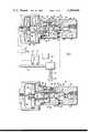
- FIG. 1is a schematic view of a downhole safety valve arrangement for an oil or gas well, with a dump valve detailed in longitudinal section and showing the novel stable seal arrangement.
- FIG. 2is a similar view of the dump valve of FIG. 1 in a different position.
- FIG. 3is a sectional view similar to FIG. 2, with the plunger shifted to dump position, and the spring being omitted.
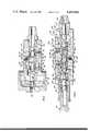
- FIG. 4is a cross-section detailing a high-low sensing pilot valve embodying the invention.
- FIG. 1shows a wellhead 6 on a well 8 having a downhole safety valve 10, which responds to excessive or deficient downhole pressure to cut off the flow of well fluids (gas, oil, etc.) to the wellhead, and delivery pipe line 12.
- High and low pressure sensors 14 and 16communicate with the delivery line to initiate corrective flow of hydraulic fluid from supply 18 through relay pilot 20 and dump valve 21 to wellhead 6 and safety valve 10.
- Dump valve 21comprises a first body portion 22 forming a piston chamber 24 in which works a piston 26 constantly urged leftwardly to a stop position closing end opening 28 which is connected to hydraulic fluid supply 18.
- the righthand side of piston 26abuts the adjacent end of a plunger extension 30 extending axially within a piston biasing spring 32.
- Plunger extension 30is threadedly secured at its opposite end 31 to the adjacent end of main plunger member 34 which extends axially through annular valve chamber 36 formed by a bore within second body portion 38.
- Plunger extension 30has a restricted terminal extension 33 with an O-ring seal 35 received in a bore 37 in piston 26.
- First body portion 22has an externally threaded bore 40 secured in internally threaded cup 42 in the second body portion 38.
- Plunger Extension 30extends through a restricting collar 44 between enlarged bore portion 46 in piston chamber 24 and the left end of valve chamber 36, O-ring 48 is mounted adjacent collar 44 and secured by a split ring 50. At its opposite end, the main plunger 34 slides through internal collar 52 and is there sealed by an O-ring 54 also held in place and confined by a split ring 56. Main plunger member 34 is positioned to enter restricted orifice or bore 58 in fluid communication with adjacent threaded fitting 60, and is provided with an O-ring seal 62. An opening 64 for hydraulic fluid supply opens into the left end portion of valve chamber 36 through a port or orifice 66 in the wall defining chamber 36.
- a second threaded opening 68opens through a port 70 into the right end portion of valve chamber 36 on the side of O-ring seal 54 opposite port 66. Opening 68 is connected to the controlled downhole safety valve 10.
- the O-rings which control very high pressures, as 48 and 54,are made of a relatively soft elastomeric material of durometer hardness around ninety (90) for best results in order to remain bubble tight. A durometer hardness of between around fifty (50) and one hundred thirty (130) will provide satisfactory results.
- FIG. 2shows the form of FIG. 1 with piston 26 urged rightwardly by hydraulic pressure from the high-low sensors 14, 16, indicating existence of pressures in the desired range in flowline 12. Due to the differential area at the right end 31 of plunger extension 30, any hydraulic pressure in valve chamber 36 will urge piston 26 leftwardly against the control pressure in hydraulic fitting 28. Pilot supply pressure applied through opening 28, indicating proper pressure range in pipe 12, will urge piston 26 and the plunger rightwardly against this differential force and spring 32. Spring 32, provided as a precaution, will close opening 28 to hydraulic fluid supply 18 in case of failure of pressure in valve chamber 36.
- FIG. 3is similar to FIGS. 1 and 2, but with the spring 32 omitted.
- a light spring 32preferably will be provided as a safety feature, in case of failure of pressure, permitting the downhole safety valve actuator to dump and the safety valve to close.
- an internal, longitudinal passage 76 in the main valve plunger member 34is connected to the external surface of the plunger member by cross or radial ports or ducts 78 and 80 each in quadrature, through which hydraulic fluid is conducted across soft O-ring seal 54 (FIG. 2).
- ducts or ports 80confront the plunger rubbing face of seal 54 and pressure in the valve chamber is thereby applied directly through these ports against the seal 54.
- each cross duct 80is not greater than the thickness of the plunger engaging surfaces of seal 80, collar 52, and split ring 56; radial outward pressure applied through ducts 80 cannot extrude the seal from its groove. In other words, there is no free space immediately around the seal, except ducts or ports 80, either within the surfaces of the bore wall or the plunger member 34, into which the seal can extrude even at very high pressures.
- FIG. 4shows the soft seal protecting feature applied to a high pressure sensor valve designed to handle pressures of 10,000 psi or higher.
- the valve bodyis formed by a left end extension 84 enclosing an actuating stem 86 with a collar 88 against which a compression spring 90 bears. The opposite end of the spring bears against an adjusting knob 92.
- An intermediate body part 94has internal openings 96 and 98 at its ends threadedly secured by means of adapters 100 and 102 to body extension 84 and a fitting 104 for connection to the pressure source to be monitored.
- Intermediate body part 94has a reduced central bore 106 in which is received a pair of sleeves 107 and 108 with central bores 115 and 117 and connected at their opposite ends to and secured in position by adapters 100 and 102.
- O-ring seals 111, 112, 113, and 114are provided between the abutting surfaces of body part 102 and sleeves 107 and 108.
- Body part 102has threaded high-low pressure hydraulic inlets 116 and 118 and a threaded outlet 120 for connection to the controlled instrumentation.
- O-ring soft seals 122, 123, 124, and 125are provided between sleeve bore 115 and 117 and main plunger member 110.
- Hydraulic inlet 116connects through a port 128 in the body part and annulus 130 in sleeve 107 with an annular recess or valve chamber 132 in the wall of sleeve bore 115 between plunger seals 122 and 123.
- Inlet 118connects through ports 134 in the body part and 136 in sleeve 108 with an annular recess of valve chamber 138 in the latter sleeve between soft seals 124 and 125.
- Outlet 120connects through port 142 with the annular clearance 144 between sleeves 107 and 108.
- Main plunger part 110has a pair of spaced apart central longitudinal passages 146 and 148, each connected at its ends by cross or radial ducts 150 and 152 and 154 and 156 to the outer surface of the plunger. At its left end, plunger part 110 has a depression 158 against which the pointed end 160 of stem 86 bears for transmitting the force of spring 90 to plunger part 110. At its opposite end, part 110 abuts a piston 162 with a valving extension 164 which may enter and close the bore 166 in fitting 104.
- valve plungerwill be in the position shown with hydraulic pressure transmitted through inlet 116 to valve chamber recess 132, thence through cross ducts 150, internal passage 146 and cross ducts 152, and clearance 144 and outlet 120 to the corrective instrumentation, maintaining the latter in normal operative condition. If excessive pressure should be applied to plunger extension 164 and piston 162, plunger 110 would be shifted leftwardly against spring 90 to move both cross ducts 150 and 152 on the left side of seal 123 and thereby separated from clearance 144. At the same time, cross ducts 154 will move leftwardly across seal 124, thus communicating clearance 144 and outlet 120 with low-pressure inlet 118, permitting the controlled instrumentality to vent through 120 and 118.
- seal 123may be passed over by duct 152 when transmitting pressured fluid flow in either direction from outlet 120. While portions of seal 123 are abreast of ducts 152, wholly or in part, all adjacent parts of the seal are supported and confined by portions of the plunger or confronting bore. This is made possible by the unique channeling of the stream of pressured fluid (liquid or gas) being manipulated by the plunger internally through the plunger from restricted ducts therein, instead of through recesses in faces of the plunger or valve body bore.
- Seals 123 and 124are formed of a soft elastomeric material of a durometer hardness between around fifty (50) and one hundred thirty (130) for high fluid pressures, such as over 5,000 psi. Best results are obtained with a durometer hardness of around one hundred (100).
- a soft elastomeric sealtolerances between adjacent parts can be relatively large while bubble tight sealing is effected by the soft seals. Also, foreign matter will not tend to settle or collect about a soft seal.
- the diameter of seals 123 and 124is around the same diameter as the diameter of the cross ducts 150, 152, 154, and 156.
- the cross ductsdo not provide a void space adjacent seals 123 and 124 into which the soft seals can be extruded.
- the novel arrangement of seal confining wallsleaves only the portion of the seal directly exposed to a port or duct containing the pressured fluid so that the seal material cannot be extruded from its receiving groove.
Landscapes
- Engineering & Computer Science (AREA)
- General Engineering & Computer Science (AREA)
- Mechanical Engineering (AREA)
- Fluid-Driven Valves (AREA)
Abstract
Description
Claims (1)
Priority Applications (1)
| Application Number | Priority Date | Filing Date | Title |
|---|---|---|---|
| US05/939,165US4209040A (en) | 1978-09-01 | 1978-09-01 | Seal means for high pressure control valves |
Applications Claiming Priority (1)
| Application Number | Priority Date | Filing Date | Title |
|---|---|---|---|
| US05/939,165US4209040A (en) | 1978-09-01 | 1978-09-01 | Seal means for high pressure control valves |
Publications (1)
| Publication Number | Publication Date |
|---|---|
| US4209040Atrue US4209040A (en) | 1980-06-24 |
Family
ID=25472654
Family Applications (1)
| Application Number | Title | Priority Date | Filing Date |
|---|---|---|---|
| US05/939,165Expired - LifetimeUS4209040A (en) | 1978-09-01 | 1978-09-01 | Seal means for high pressure control valves |
Country Status (1)
| Country | Link |
|---|---|
| US (1) | US4209040A (en) |
Cited By (16)
| Publication number | Priority date | Publication date | Assignee | Title |
|---|---|---|---|---|
| US4312379A (en)* | 1978-02-16 | 1982-01-26 | Trw Inc. | Pressure actuated multiway valve |
| US4491154A (en)* | 1983-05-09 | 1985-01-01 | Joy Manufacturing Company | Double acting pilot valve |
| US4530377A (en)* | 1983-08-08 | 1985-07-23 | Joy Manufacturing Company | Block valve |
| US4616806A (en)* | 1983-09-22 | 1986-10-14 | Jetco, Inc. | Valve |
| US4643228A (en)* | 1984-03-02 | 1987-02-17 | Sigma Enterprises, Inc. | Convertible high or low pressure pilot valve |
| US4726398A (en)* | 1986-12-16 | 1988-02-23 | Marathon Oil Company | High speed, high temperature three-way valve for switching high pressure fluids under low pressure control |
| USRE33246E (en)* | 1986-12-16 | 1990-07-03 | Marathon Oil Company | High speed, high temperature three-way valve for switching high pressure fluids under low pressure control |
| US5647575A (en)* | 1993-11-23 | 1997-07-15 | Sarcos Group | Volumetric shaft/valve |
| US5762316A (en)* | 1995-10-04 | 1998-06-09 | Kraft Foods, Inc. | Valve mechanism with improved sealing |
| US6497244B2 (en) | 2000-03-02 | 2002-12-24 | David Needham | Fluid flow proportioning device |
| US20060016492A1 (en)* | 2004-04-26 | 2006-01-26 | Muller Falk R | Pressure control valve |
| US20130213505A1 (en)* | 2012-02-22 | 2013-08-22 | King Nutronics Corporation | Multi-fluid precision calibration pressure source |
| US20140246898A1 (en)* | 2011-11-08 | 2014-09-04 | Robert Bosch Gmbh | Hydraulically Actuated Regulating Valve for a Vehicle Brake System, and Associated Vehicle Brake System |
| WO2019099563A1 (en)* | 2017-11-15 | 2019-05-23 | Fhe Usa Llc | Positive engagement indicator for remotely operated well pressure control apparatus |
| US10550659B2 (en) | 2018-03-28 | 2020-02-04 | Fhe Usa Llc | Remotely operated fluid connection and seal |
| US12252949B2 (en) | 2018-03-28 | 2025-03-18 | Fhe Usa Llc | Fluid connection assembly with adapter release |
Citations (8)
| Publication number | Priority date | Publication date | Assignee | Title |
|---|---|---|---|---|
| US2645450A (en)* | 1948-11-26 | 1953-07-14 | C B Hunt & Son Inc | Fluid valve means |
| FR1207849A (en)* | 1958-07-18 | 1960-02-18 | Homestead Valve Mfg Co | Multi-way slide valves for pressurized fluids |
| US3000610A (en)* | 1958-10-13 | 1961-09-19 | Grove Valve & Regulator Co | Valve construction |
| US3138175A (en)* | 1960-11-22 | 1964-06-23 | Futurecraft Corp | High pressure modulating valve |
| US3415282A (en)* | 1965-11-23 | 1968-12-10 | Robertshaw Controls Co | Pneumatic diverting relay |
| US3744523A (en)* | 1971-07-21 | 1973-07-10 | J Hill | Fluid pilot valve |
| US3790128A (en)* | 1955-05-25 | 1974-02-05 | Argus Gmbh | Device for transferring fluids |
| US3927830A (en)* | 1974-09-25 | 1975-12-23 | Borg Warner | Control valve |
- 1978
- 1978-09-01USUS05/939,165patent/US4209040A/ennot_activeExpired - Lifetime
Patent Citations (8)
| Publication number | Priority date | Publication date | Assignee | Title |
|---|---|---|---|---|
| US2645450A (en)* | 1948-11-26 | 1953-07-14 | C B Hunt & Son Inc | Fluid valve means |
| US3790128A (en)* | 1955-05-25 | 1974-02-05 | Argus Gmbh | Device for transferring fluids |
| FR1207849A (en)* | 1958-07-18 | 1960-02-18 | Homestead Valve Mfg Co | Multi-way slide valves for pressurized fluids |
| US3000610A (en)* | 1958-10-13 | 1961-09-19 | Grove Valve & Regulator Co | Valve construction |
| US3138175A (en)* | 1960-11-22 | 1964-06-23 | Futurecraft Corp | High pressure modulating valve |
| US3415282A (en)* | 1965-11-23 | 1968-12-10 | Robertshaw Controls Co | Pneumatic diverting relay |
| US3744523A (en)* | 1971-07-21 | 1973-07-10 | J Hill | Fluid pilot valve |
| US3927830A (en)* | 1974-09-25 | 1975-12-23 | Borg Warner | Control valve |
Cited By (24)
| Publication number | Priority date | Publication date | Assignee | Title |
|---|---|---|---|---|
| US4312379A (en)* | 1978-02-16 | 1982-01-26 | Trw Inc. | Pressure actuated multiway valve |
| US4491154A (en)* | 1983-05-09 | 1985-01-01 | Joy Manufacturing Company | Double acting pilot valve |
| US4530377A (en)* | 1983-08-08 | 1985-07-23 | Joy Manufacturing Company | Block valve |
| US4616806A (en)* | 1983-09-22 | 1986-10-14 | Jetco, Inc. | Valve |
| US4643228A (en)* | 1984-03-02 | 1987-02-17 | Sigma Enterprises, Inc. | Convertible high or low pressure pilot valve |
| USRE33246E (en)* | 1986-12-16 | 1990-07-03 | Marathon Oil Company | High speed, high temperature three-way valve for switching high pressure fluids under low pressure control |
| US4726398A (en)* | 1986-12-16 | 1988-02-23 | Marathon Oil Company | High speed, high temperature three-way valve for switching high pressure fluids under low pressure control |
| US5647575A (en)* | 1993-11-23 | 1997-07-15 | Sarcos Group | Volumetric shaft/valve |
| US5762316A (en)* | 1995-10-04 | 1998-06-09 | Kraft Foods, Inc. | Valve mechanism with improved sealing |
| US6497244B2 (en) | 2000-03-02 | 2002-12-24 | David Needham | Fluid flow proportioning device |
| US20060016492A1 (en)* | 2004-04-26 | 2006-01-26 | Muller Falk R | Pressure control valve |
| US7497232B2 (en)* | 2004-04-26 | 2009-03-03 | Hydraulik-Ring Gmbh | Pressure control valve |
| US20140246898A1 (en)* | 2011-11-08 | 2014-09-04 | Robert Bosch Gmbh | Hydraulically Actuated Regulating Valve for a Vehicle Brake System, and Associated Vehicle Brake System |
| US20130213505A1 (en)* | 2012-02-22 | 2013-08-22 | King Nutronics Corporation | Multi-fluid precision calibration pressure source |
| US9309898B2 (en)* | 2012-02-22 | 2016-04-12 | King Nutronics Corporation | Multi-fluid precision calibration pressure source |
| US10385835B2 (en)* | 2012-02-22 | 2019-08-20 | King Nutronics Corporation | Multi-fluid precision calibration pressure source |
| US11913439B2 (en) | 2012-02-22 | 2024-02-27 | King Nutronics, Llc | Multi-fluid precision calibration pressure source |
| WO2019099563A1 (en)* | 2017-11-15 | 2019-05-23 | Fhe Usa Llc | Positive engagement indicator for remotely operated well pressure control apparatus |
| US10550659B2 (en) | 2018-03-28 | 2020-02-04 | Fhe Usa Llc | Remotely operated fluid connection and seal |
| US10907435B2 (en) | 2018-03-28 | 2021-02-02 | Fhe Usa Llc | Fluid connection and seal |
| US11313195B2 (en) | 2018-03-28 | 2022-04-26 | Fhe Usa Llc | Fluid connection with lock and seal |
| US11692408B2 (en) | 2018-03-28 | 2023-07-04 | Fhe Usa Llc | Fluid connection assembly |
| US12173577B2 (en) | 2018-03-28 | 2024-12-24 | Fhe Usa Llc | Locking fluid connection with seal |
| US12252949B2 (en) | 2018-03-28 | 2025-03-18 | Fhe Usa Llc | Fluid connection assembly with adapter release |
Similar Documents
| Publication | Publication Date | Title |
|---|---|---|
| US4209040A (en) | Seal means for high pressure control valves | |
| US5341835A (en) | Lubrication system for valve seat of a gate valve | |
| US3497177A (en) | Seat and seal assembly for valves | |
| US4434967A (en) | Valve self-relieving seats | |
| US4679765A (en) | Low leakage orifice-controlled poppet valve | |
| US5533738A (en) | Pressure controlled apparatus for sealing shutoff devices located in pipelines | |
| US6672561B2 (en) | Piston diaphragm with integral seal | |
| US4506693A (en) | Pressure regulating valve | |
| US4527630A (en) | Hydraulic actuating means for subsurface safety valve | |
| US3215157A (en) | Valve seat structure having pressureactuated seal means | |
| US6843266B2 (en) | Regulator with erosion resistant seal assemblies | |
| US4041970A (en) | Quick bleed exhaust valve | |
| US3538938A (en) | Automatic sealant sealed valves | |
| US2727530A (en) | Regulator valve | |
| US4997159A (en) | Logic valve | |
| US2969775A (en) | Valve | |
| GB2582747A (en) | Device for controlling fluid flow | |
| USRE29299E (en) | Self sealing gate valve | |
| US7322373B2 (en) | High accuracy low leakage valve for high pressure applications | |
| US3633608A (en) | Gas pressure regulating valve | |
| GB2216990A (en) | Override check valve | |
| US4913400A (en) | Double disk gate valve | |
| US3856261A (en) | Pressure relief means for valve body chamber | |
| US3747627A (en) | Pressure regulator and compensator | |
| US4347867A (en) | Safety valve |
Legal Events
| Date | Code | Title | Description |
|---|---|---|---|
| AS | Assignment | Owner name:JOY MANUFACTURING COMPANY 301 GRANT STREET PITTSBU Free format text:ASSIGNMENT OF ASSIGNORS INTEREST.;ASSIGNOR:ACF INDUSTRIES, INCORPORATED A NEW JERSEY CORP;REEL/FRAME:004280/0243 Effective date:19840525 | |
| AS | Assignment | Owner name:ACF INDUSTRIES, INCORPORATED, 750 THIRD AVE., NEW Free format text:ASSIGNMENT OF ASSIGNORS INTEREST.;ASSIGNOR:W-K-M WELLHEAD SYSTEMS, INC.;REEL/FRAME:004284/0238 Effective date:19840525 | |
| AS | Assignment | Owner name:COOPER INDUSTRIES, INC. Free format text:ASSIGNMENT OF ASSIGNORS INTEREST.;ASSIGNOR:JOY MANUFACTURING COMPANY;REEL/FRAME:004688/0506 Effective date:19870204 Owner name:COOPER INDUSTRIES, INC.,TEXAS Free format text:ASSIGNMENT OF ASSIGNORS INTEREST;ASSIGNOR:JOY MANUFACTURING COMPANY;REEL/FRAME:004688/0506 Effective date:19870204 | |
| AS | Assignment | Owner name:COOPER CAMERON CORPORATION, TEXAS Free format text:ASSIGNMENT OF ASSIGNORS INTEREST;ASSIGNOR:COOPER INDUSTRIES, INC.;REEL/FRAME:007462/0622 Effective date:19950417 |