US4203626A - Articulated boom-dipper-bucket assembly for a tunnel boring machine - Google Patents
Articulated boom-dipper-bucket assembly for a tunnel boring machineDownload PDFInfo
- Publication number
- US4203626A US4203626AUS06/013,523US1352379AUS4203626AUS 4203626 AUS4203626 AUS 4203626AUS 1352379 AUS1352379 AUS 1352379AUS 4203626 AUS4203626 AUS 4203626A
- Authority
- US
- United States
- Prior art keywords
- boom
- pivotally connected
- dipper
- base
- bulkhead
- Prior art date
- Legal status (The legal status is an assumption and is not a legal conclusion. Google has not performed a legal analysis and makes no representation as to the accuracy of the status listed.)
- Expired - Lifetime
Links
- 230000000712assemblyEffects0.000claimsdescription23
- 238000000429assemblyMethods0.000claimsdescription23
- 239000000463materialSubstances0.000claimsdescription23
- 230000015572biosynthetic processEffects0.000claimsdescription12
- 230000007246mechanismEffects0.000abstractdescription9
- 210000000481breastAnatomy0.000description18
- 239000004567concreteSubstances0.000description5
- 238000010276constructionMethods0.000description5
- 230000007423decreaseEffects0.000description2
- 239000011178precast concreteSubstances0.000description2
- 230000005641tunnelingEffects0.000description2
- 210000000078clawAnatomy0.000description1
- 210000005069earsAnatomy0.000description1
- 238000000034methodMethods0.000description1
- 239000011435rockSubstances0.000description1
Images


Classifications
- E—FIXED CONSTRUCTIONS
- E21—EARTH OR ROCK DRILLING; MINING
- E21D—SHAFTS; TUNNELS; GALLERIES; LARGE UNDERGROUND CHAMBERS
- E21D9/00—Tunnels or galleries, with or without linings; Methods or apparatus for making thereof; Layout of tunnels or galleries
- E21D9/10—Making by using boring or cutting machines
- E21D9/1093—Devices for supporting, advancing or orientating the machine or the tool-carrier
- E—FIXED CONSTRUCTIONS
- E21—EARTH OR ROCK DRILLING; MINING
- E21D—SHAFTS; TUNNELS; GALLERIES; LARGE UNDERGROUND CHAMBERS
- E21D9/00—Tunnels or galleries, with or without linings; Methods or apparatus for making thereof; Layout of tunnels or galleries
- E21D9/06—Making by using a driving shield, i.e. advanced by pushing means bearing against the already placed lining
- E21D9/0642—Making by using a driving shield, i.e. advanced by pushing means bearing against the already placed lining the shield having means for additional processing at the front end
- E21D9/065—Making by using a driving shield, i.e. advanced by pushing means bearing against the already placed lining the shield having means for additional processing at the front end with devices for provisionally supporting the front face
- E—FIXED CONSTRUCTIONS
- E21—EARTH OR ROCK DRILLING; MINING
- E21D—SHAFTS; TUNNELS; GALLERIES; LARGE UNDERGROUND CHAMBERS
- E21D9/00—Tunnels or galleries, with or without linings; Methods or apparatus for making thereof; Layout of tunnels or galleries
- E21D9/06—Making by using a driving shield, i.e. advanced by pushing means bearing against the already placed lining
- E21D9/08—Making by using a driving shield, i.e. advanced by pushing means bearing against the already placed lining with additional boring or cutting means other than the conventional cutting edge of the shield
- E21D9/0875—Making by using a driving shield, i.e. advanced by pushing means bearing against the already placed lining with additional boring or cutting means other than the conventional cutting edge of the shield with a movable support arm carrying cutting tools for attacking the front face, e.g. a bucket
Definitions
- the field of the inventionis tunnel boring machines. More specifically, the present invention relates to a tunnel boring machine having an articulated excavator and a breast plate assembly.
- tunnel boring machinesFor digging a tunnel through material of intermediately hardness and containing loose earth and rock.
- Such tunnel boring machinestypically include a heavy style hollow cylindrical body having a front circular cutting edge and a central axis.
- An excavatoris mounted at the front end of the machine within the cylinder and generally on the central axis of the machine.
- a conveyoris mounted within the cylindrical body with a loading end thereof situated adjacent the bottom portion of the circular cutting edge. The excavator is operable to cut through material at the front of the machine and move it onto the conveyor.
- a trackon which flat cars containing concrete segments can travel to bring segments to the tunnel boring machine and on which gondola cars can travel to the machine for receiving material from the conveyor and carrying the material out of the tunnel.
- the tunnel boring machineIn digging a tunnel, the tunnel boring machine is positioned at the front of the beginning portion of a tunnel liner.
- Retractable jack assemblieseach including a plurality of jacks are located at the read edge of the cylindrical body and positioned between the rear edge and the front edge of the tunnel liner being formed. The jacks are then extended in increments to force the front circular cutting edge against the material being excavated.
- the excavatoris operated to remove the material at the front end of the cylindrical body.
- the jacksare extended to push the cutting edge against the material at the outer periphery of the hold being dug by the excavator to finish the cut of the hold to form the tunnel.
- the jacksAfter the jacks have been extended a predetermined distance, at least equal to the width of the precast quarter-cylindrical segments, the jacks are contracted and the jack assemblies are retracted. Then four concrete segments are positioned in a ring in the space vacated by the retracted jack assemblies the cylindrical body and against the front edge of the tunnel liner.
- the jack assembliesare positioned in the space between the new front edge of the liner formed by the four concrete segments just laid in place and the excavator is operated again to dig a hole in the material at the front of the tunnel boring machine.
- the jacksare periodically extended to push the cylindrical body member toward the hole being dug and to finish the cut of the hole at the outer periphery thereof.
- a plurality of breast platesare provided hingedly connected to the inner periphery of the cylindrical body.
- such breast platesare arranged in an assembly to form a partially annular shield beneath the top portion of the circular cutting edge of the cylindrical body and above the excavator.
- Piston and cylinder assembliesare associated with the breast plates for pivoting the breast plates upwardly to hold material from falling into the machine.
- the excavatorsoften included a bucket-boom assembly comprising a bucket-scoop pivotally mounted at the front end of a boom which is mounted to a bulkhead that can be reciprocated along the central axis of the machine.
- the boomis rotatable 360° about the central axis and is pivotally mounted to the bulkhead.
- the assemblyincludes two reciprocal power mechanisms, one for pivoting the boom about the central axis and another for pivoting the bucket-scoop about the outer end of the boom.
- the articulated boom-dipper-bucket assembly of the present inventionprovides an excavator which has five degrees of movement with the addition of a dipper member to the assembly. With five degrees of motion, a more uniform breakout force is obtained across the radial extent of movement of the bucket-scoop of the excavator from the central axis of the machine to the circular cutting edge of the machine.
- an articulated boom-dipper-bucket assemblyfor a tunnel boring machine of the type which includes a hollow cylindrical body having a front circular cutting edge and a central axis, an excavator including a bulkhead, mounting means for mounting the bulkhead on the central axis of the cylindrical body, moving means associated with the excavator for moving the bulkhead axially of the cylindrical body, and rotating means for rotating the excavator 360° about an axis coaxial with or parallel to the central axis, said assembly forming part of the excavator and including a base mounted on the bulkhead and having a front face facing axially toward the front of said machine, an elongate boom having a first inner end pivotally mounted to said base at one side thereof, an elongate dipper member pivotally mounted at a first end thereof to an outer second end of said boom and a bucket-scoop having an inner edge and an outer cutting edge and being pivotally mounted to a second outer end of said dipper member, first reciprocal power means pivot
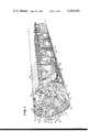
- FIG. 1is a perspective view with portions broken away of a tunnel boring machine utilizing one embodiment of the articulated boom-dipper-bucket assembly of the present invention.
- FIG. 2is a larger perspective view of the front end of the tunnel boring machine shown in FIG. 1 with another embodiment of the articulated boom-dipper-bucket assembly of the present invention shown therein.
- FIG. 3is a fragmentary vertical side view with portions broken away of the embodiment of the boom-dipper-bucket assembly shown in FIG. 2 with the assembly in a bucket-raised position.
- FIG. 4is a graph comparing the breakout force in tons of a prior art boom-bucket assembly with the breakout force in tons of the articulated boom-dipper-bucket assembly of the present invention.
- FIG. 1a tunnel boring machine 10 for tunneling through material of intermediate hardness.
- the machine 10includes a hollow cylindrical body 12 having a front circular cutting edge 14 and a rear edge 15.
- One of several jack assemblies 16comprising a plurality of jacks 17 is shown positioned between the rear edge 15 of the cylindrical body 12 and the front edge of a tunnel liner 18 which is formed in increments from quarter-cylindrical precast concrete segments 20.
- the jacks 17are operated to push the cutting edge 14 against the periphery of the hole being dug to finish the "cut" of the cylindrical hole. Then after the jacks 17 have been fully extended, they are contracted and then the jack assemblies 16 are retracted from the position shown so that four of the concrete segments 20 can be positioned in a ring to form another increment of the tunnel liner 18. The the jack assemblies 16 are repositioned between the rear edge 15 and the front edge of the tunnel liner 18 for pushing the tunnel boring machine 10 against the material through which the machine is tunneling.
- a track 24is laid in the tunnel for carrying flat cars 26 that carry concrete segments 20 to the machine 10 and for carrying gondola cars 28 that are used to haul away material as it is excavated from the front of the tunnel.
- the machine 10also includes an excavator 30 which is mounted at the front end of the machine 10 and a conveyor 32 for conveying excavated material from the bottom front of the machine 10 upwardly to a position over the forwardmost gondola car 28.
- an excavator 30which is mounted at the front end of the machine 10 and a conveyor 32 for conveying excavated material from the bottom front of the machine 10 upwardly to a position over the forwardmost gondola car 28.
- a breast plate assembly 34comprising a plurality of breast plates 36 is mounted at the top front of the machine adjacent to and beneath the upper portion of the cylindrical cutting edge 14 and above the excavator 30.
- each of the plates 36has a generally trapezoidal shape.
- the platescan be pivoted downwardly to form a partially annular shield as shown in FIG. 1 by piston and cylinder assemblies 38.
- the excavator 30is constructed and arranged to have five degrees of movement.
- the excavator 30includes a bulkhead 40 which has a rail 42 mounted on each side thereof.
- Each of the rails 42is received within a channel member 44 fixed within and to the cylindrical body 12.
- a piston and cylinder assembly(not shown) is provided for reciprocating the bulkhead 40 with the rails 42 sliding in the channels 44.
- Mounted to the bulkhead 40is a base 46 having a front face 48 which faces axially toward the front of the machine.
- a mechanism(not shown) is provided for rotating the base 360° in a plane normal to the central axis of the cylindrical body 12.
- a first inner end 50 of a boom 52is pivotally mounted to the base 46 adjacent one side 54 thereof.
- a second outer end 56 of the boom 52is pivotally connected to an elongate dipper member 58 at a location between a first inner end 60 of the dipper member 58 and a second outer end 62 of the dipper member 58.
- Pivotally mounted to the second end 62 of the dipper memberis a bucket-scoop 13 having the general shaft of a claw with a front cutting edge 64 and an inner edge 65.
- a first pair of boom piston and cylinder assemblies 66are each pivotally connected at a first end to the base 46 at a side 68 thereof opposite the side 54 of the base 46.
- a second or outer end of each piston and cylinder assembly 66is pivotally connected to the boom 52 at a point intermediate the ends 50 and 56 thereof.
- a second pair of dipper piston and cylinder assemblies 72are pivotally connected at one end to the inner end 50 of the boom 52 and at the other end to the inner end 60 of the dipper member 58.
- Another bucket piston and cylinder assembly 80is pivotally connected between the inner end 60 of the dipper member 58 and the inner edge 65 of the bucket-scoop 63.
- the first degree of motionis the reciprocal motion provided by the power mechanism for reciprocating the bulkhead in the channels 44. This movement provides an in and out movement of the excavator 30 along the central axis of the cylindrical body 12.
- a second degree of movementis provided by the rotational mounting of the base 46 on the bulkhead 40.
- a third degree of movementis provided by the boom piston and cylinder assemblies 66 which provide for movement of the outer end 56 of the boom 52 to and away from the central axis.
- a fourth degree of movementis provided by the dipper piston and cylinder assemblies 72 which provide pivoting movement of the dipper member 58 about the outer end 56 of the boom 52.
- the tunnel boring machineis generally identified by the reference numeral 110 and includes a cylindrical body 112 having a front cylindrical cutting edge 114.
- An excavator 130 similar to the excavator 30is mounted within the body 112 on the central axis thereof.
- a breast plate assembly 134 similar to the breast plate assembly 34is provided.
- the assembly 134includes a plurality of generally trapezoidal shaped breast plates which can be pivoted downwardly to the position shown in FIG. 2 by piston and cylinder assemblies 138 to form a partially annular shield for preventing material from falling into the machine 110.
- the excavator 130includes a bulkhead 140 having a rail 142 mounted on each side thereof. Each of the rails 142 is received within and slidably movable within one of two channel members 144 positioned on either side of the bulkhead 140 and fixed within the cylindrical body 112. Mounted on the bulkhead is a base 146 having a front face 148 which faces axially outwardly toward the front of the machine 110. A first inner end 150 of a boom 152 is pivotally connected to the front face 148 of the base 146 adjacent one side 154 of the base 146.
- a second outer end 156 of the boom 152is pivotally connected to an elongate dipper member 158 at the inner end 160 thereof.
- a second outer end 162 of the dipper member 158is pivotally connected to a bucket-scoop 163 having an outer cutting edge 164 and an inner edge 165.
- a single boom piston and cylinder assembly 166is pivotally connected at one end to the base 146 at a side 168 thereof opposite the side 154.
- the outer end of the boom piston and cylinder assembly 166is pivotally connected to the boom 152 at a point between the ends 150 and 156 thereof.
- a pair of dipper piston and cylinder assemblies 172are each pivotally connected at one end to the inner end 153 of the boom 150 and at the other end to the inner end 160 of the dipper member 158.
- a pair of bucket piston and cylinder assemblies 180is pivotally connected a one end to the inner end 160 of dipper member 158 and at the other end to the inner edge 165 of the bucket-scoop 163.
- the excavator 30utilizes two boom piston and cylinder assemblies 66 and one bucket piston and cylinder assembly 80 whereas the excavator 130 utilized one boom piston and cylinder assembly 166 and two bucket piston and cylinder assemblies 180.
- the boom 152has an inner side 181 which is the closest side of the boom 152 to the base 146 and an outer side 183.
- the outer side 183is slightly convex so as to have a projecting portion 184 which is located between the ends 150 and 156 of the boom 152.
- the pivot connection of the boom piston and cylinder assembly 166is located in the projecting portion 184 as shown in FIG. 3.
- the boom 152has a generally L shaped configuration with an ear formation 186 extending from the inner side 181 of the boom and outwardly from the inner end 150 of the boom 152. As shown, the inner end of the dipper piston and cylinder assemblies 172 is pivotally connected to the ear formation 186.
- the dipper member 158also has a generally L shaped configuration with a short leg 190 extending outwardly from the inner end 160 of the dipper member 158.
- This short leg 190is of sufficient width to provide for two pivot connections, one pivot connection being to the outer end of the piston and cylinder assembly 172 and the other pivot connection being of the inner end of the bucket piston and cylinder assemblies 180.
- the ear formation 180 and short leg formation 190have been described as a unitary formation, it will be apparent from FIG. 2 that the ear formation 186 actually consists of two ears, one on each side of the boom 152 and the short leg formation 190 of the dipper member actually consists of two legs on either side of the dipper member.
- a ring 201Extending from a back side 200 of the base 146 is a ring 201 which is received within the inner periphery of a cylindrical portion 202 of the bulkhead 140. Positioned between the ring 201 and the cylindrical portion 202 are roller bearings 205 which permit smooth rotation of the base 146 relative to the circular portion 202 of the bulkhead 140.
- gear teeth 208On the inner periphery of the ring 201 are provided gear teeth 208.
- gear teeth 208mounted to the bulkhead 140 are two motors one of which, 210, is shown in FIG. 3.
- Each of the motors 210has a pinion gear 212 mounted on the shaft thereof in position to engage the gear teeth 208 for rotating the base 146 relative to the bulkhead 140.
- the excavator 130also has the same five degrees of movement found in the excavator 30.
- Empirical tests conducted with the excavator 30 and the excavator 130have shown that the breakout force at the cutting edge 164 of the bucket-scoop 163 is substantially uniform about the total circular area of movement of the bucket-scoop 163 from the central axis of the cylindrical body 12 radially outwardly to a point near the circumference of the cylindrical body 12. This is best shown in FIG. 4 where the breakout force for a boom-bucket assembly combination of known type is greatest at the center where the breakout force is approximately 97 tons and decreases to roughly 42 tons at the outer radial position of the bucket of the boom-bucket combination which is approximately 16 feet from the central axis.
- the breakout force of the boom-dipper-bucket assembly combination of the present inventionhas a maximum force of roughly 82 tons at the central axis and decreases only slightly to about 75 tons at the outer radial position of the bucket-scoop 63 or 163 of the assembly. Accordingly, a strong and generally uniform breakout force is provided at all of the positions of the bucket-scoop 63 or 163 of the evacator 30 or 130.
Landscapes
- Engineering & Computer Science (AREA)
- Mining & Mineral Resources (AREA)
- Environmental & Geological Engineering (AREA)
- Life Sciences & Earth Sciences (AREA)
- General Life Sciences & Earth Sciences (AREA)
- Geochemistry & Mineralogy (AREA)
- Geology (AREA)
- Earth Drilling (AREA)
- Excavating Of Shafts Or Tunnels (AREA)
- Underground Or Underwater Handling Of Building Materials (AREA)
- Drilling And Exploitation, And Mining Machines And Methods (AREA)
Abstract
Description
Claims (12)
Priority Applications (7)
| Application Number | Priority Date | Filing Date | Title |
|---|---|---|---|
| US06/013,523US4203626A (en) | 1979-02-21 | 1979-02-21 | Articulated boom-dipper-bucket assembly for a tunnel boring machine |
| AT79103162TATE5015T1 (en) | 1979-02-21 | 1979-08-27 | ARTICULATED BLADE BOOM ASSEMBLY FOR A TUNNEL BORING MACHINE. |
| EP79103162AEP0014733B1 (en) | 1979-02-21 | 1979-08-27 | Articulated boom-dipper-bucket assembly for a tunnel boring machine |
| DE7979103162TDE2966300D1 (en) | 1979-02-21 | 1979-08-27 | Articulated boom-dipper-bucket assembly for a tunnel boring machine |
| CA000345924ACA1139324A (en) | 1979-02-21 | 1980-02-19 | Articulated boom-dipper-bucket assembly for a tunnel boring machine |
| JP2103680AJPS55148896A (en) | 1979-02-21 | 1980-02-21 | Jointtconnected boom* support arm and bucket assembly for tunnel excavator |
| BR8001293ABR8001293A (en) | 1979-02-21 | 1980-02-21 | ARTICULATED PUMP-DIVER AND CACAMBA SET FOR A TUNEL EXCAVATING MACHINE |
Applications Claiming Priority (1)
| Application Number | Priority Date | Filing Date | Title |
|---|---|---|---|
| US06/013,523US4203626A (en) | 1979-02-21 | 1979-02-21 | Articulated boom-dipper-bucket assembly for a tunnel boring machine |
Publications (1)
| Publication Number | Publication Date |
|---|---|
| US4203626Atrue US4203626A (en) | 1980-05-20 |
Family
ID=21760393
Family Applications (1)
| Application Number | Title | Priority Date | Filing Date |
|---|---|---|---|
| US06/013,523Expired - LifetimeUS4203626A (en) | 1979-02-21 | 1979-02-21 | Articulated boom-dipper-bucket assembly for a tunnel boring machine |
Country Status (7)
| Country | Link |
|---|---|
| US (1) | US4203626A (en) |
| EP (1) | EP0014733B1 (en) |
| JP (1) | JPS55148896A (en) |
| AT (1) | ATE5015T1 (en) |
| BR (1) | BR8001293A (en) |
| CA (1) | CA1139324A (en) |
| DE (1) | DE2966300D1 (en) |
Cited By (21)
| Publication number | Priority date | Publication date | Assignee | Title |
|---|---|---|---|---|
| US4332508A (en)* | 1979-02-28 | 1982-06-01 | Philipp Holzmann Aktiengesellschaft | Shield for tunneling and mining |
| US4387928A (en)* | 1981-03-27 | 1983-06-14 | Milwaukee Boiler Manufacturing Co. | Tunnel excavator |
| EP0095795A1 (en)* | 1982-06-02 | 1983-12-07 | Fonçages et Forages BESSAC S.A. | Machine for driving underground galleries |
| US4501448A (en)* | 1983-01-03 | 1985-02-26 | The United States Of America As Represented By The Secretary Of The Interior | Universal ripper miner |
| FR2589516A1 (en)* | 1985-11-06 | 1987-05-07 | Bessac Creusement Soutenement | Method and shield machine for digging underground galleries, particularly in aquiferous ground with little cohesion |
| US6554368B2 (en) | 2000-03-13 | 2003-04-29 | Oil Sands Underground Mining, Inc. | Method and system for mining hydrocarbon-containing materials |
| US20030160500A1 (en)* | 2002-01-09 | 2003-08-28 | Drake Ronald D. | Method and means for processing oil sands while excavating |
| US20040262980A1 (en)* | 2003-06-04 | 2004-12-30 | Watson John David | Method and means for recovering hydrocarbons from oil sands by underground mining |
| US20070039729A1 (en)* | 2005-07-18 | 2007-02-22 | Oil Sands Underground Mining Corporation | Method of increasing reservoir permeability |
| US20070044957A1 (en)* | 2005-05-27 | 2007-03-01 | Oil Sands Underground Mining, Inc. | Method for underground recovery of hydrocarbons |
| US20080017416A1 (en)* | 2006-04-21 | 2008-01-24 | Oil Sands Underground Mining, Inc. | Method of drilling from a shaft for underground recovery of hydrocarbons |
| US20080078552A1 (en)* | 2006-09-29 | 2008-04-03 | Osum Oil Sands Corp. | Method of heating hydrocarbons |
| US20080087422A1 (en)* | 2006-10-16 | 2008-04-17 | Osum Oil Sands Corp. | Method of collecting hydrocarbons using a barrier tunnel |
| US20090084707A1 (en)* | 2007-09-28 | 2009-04-02 | Osum Oil Sands Corp. | Method of upgrading bitumen and heavy oil |
| US20090100754A1 (en)* | 2007-10-22 | 2009-04-23 | Osum Oil Sands Corp. | Method of removing carbon dioxide emissions from in-situ recovery of bitumen and heavy oil |
| US20090139716A1 (en)* | 2007-12-03 | 2009-06-04 | Osum Oil Sands Corp. | Method of recovering bitumen from a tunnel or shaft with heating elements and recovery wells |
| US20090194280A1 (en)* | 2008-02-06 | 2009-08-06 | Osum Oil Sands Corp. | Method of controlling a recovery and upgrading operation in a reservoir |
| US8209192B2 (en) | 2008-05-20 | 2012-06-26 | Osum Oil Sands Corp. | Method of managing carbon reduction for hydrocarbon producers |
| US8313152B2 (en) | 2006-11-22 | 2012-11-20 | Osum Oil Sands Corp. | Recovery of bitumen by hydraulic excavation |
| US20130008723A1 (en)* | 2010-03-15 | 2013-01-10 | Vermeer Manufacturing Company | Drilling apparatus with shutter |
| CN105863664A (en)* | 2016-06-13 | 2016-08-17 | 韶关市铁友建设机械有限公司 | Excavating pipe jacking machine |
Families Citing this family (2)
| Publication number | Priority date | Publication date | Assignee | Title |
|---|---|---|---|---|
| DE4335753C2 (en)* | 1993-10-20 | 1998-07-09 | Schaeff Karl Gmbh & Co | Hydraulically driven excavator for a jacking device for underground driving |
| JP2003097499A (en)* | 2001-09-27 | 2003-04-03 | Nippon Soken Inc | Ejector |
Citations (6)
| Publication number | Priority date | Publication date | Assignee | Title |
|---|---|---|---|---|
| US3332721A (en)* | 1964-07-16 | 1967-07-25 | Nii Osnovany I Podzemnykh Soor | Device having adjustable knives for forming tunnels in soil |
| US3404920A (en)* | 1966-07-13 | 1968-10-08 | John R. Tabor | Tunneling machine with shield supported traveling excavator |
| DE1658764B1 (en)* | 1967-11-10 | 1970-04-30 | Richard Schulz Tiefbauunterneh | Device for driving tunnels, galleries or similar structures |
| US3556599A (en)* | 1968-12-10 | 1971-01-19 | Tyman H Fikse | Method of tunneling and tunneling shield with a drag loader |
| US3612609A (en)* | 1968-07-09 | 1971-10-12 | Hydrel Ag Maschf | Device for the demolishing and removal of earthwork |
| US3966256A (en)* | 1975-04-11 | 1976-06-29 | The Robbins Company | Tunneling equipment |
Family Cites Families (11)
| Publication number | Priority date | Publication date | Assignee | Title |
|---|---|---|---|---|
| DE1182282B (en)* | 1962-05-25 | 1964-11-26 | Richard Schulz Tiefbauunterneh | Dismantling and conveying equipment for excavation work when driving tunnels, tunnels or similar structures |
| JPS4716692U (en)* | 1971-03-26 | 1972-10-26 | ||
| GB1380405A (en)* | 1971-09-22 | 1975-01-15 | Lemand Eng Ltd | Earth working machines |
| DD103296A1 (en)* | 1973-04-11 | 1974-01-12 | ||
| CA1002752A (en)* | 1973-08-23 | 1977-01-04 | Caterpillar Tractor Co. | Impact material fracturing device for excavators and the like |
| DE2423171A1 (en)* | 1974-05-13 | 1975-11-20 | Linden Alimak Ab | SHAFT COMPARTMENT |
| DE2426332C3 (en)* | 1974-05-29 | 1981-06-04 | Kabushiki Kaisha Komatsu Seisakusho, Tokyo | Tunnel boring machine |
| FR2293573A1 (en)* | 1974-12-04 | 1976-07-02 | Pingon Sa | Mine gallery wall and roof scraping machine - has three pivot arms pivotally joined in series and controlled by hydraulic rams |
| AT349517B (en)* | 1975-02-03 | 1979-04-10 | Gewerk Eisenhuette Westfalia | DRIVING MACHINE FOR DRIVING TUNNELS, CITIES AND THE LIKE. |
| DE2632127A1 (en)* | 1976-07-16 | 1978-01-19 | Lockwood Bennett Ltd | Mine heading or tunnelling machine - has boom end shovel permanently fitted with tooling for loading out heading spoil |
| HU174578B (en)* | 1977-03-25 | 1980-02-28 | Ut Vasuttervezoe Vallalat | Apparatus for tunnelling particularly for stable and inhomogeneous soil conditions |
- 1979
- 1979-02-21USUS06/013,523patent/US4203626A/ennot_activeExpired - Lifetime
- 1979-08-27ATAT79103162Tpatent/ATE5015T1/ennot_activeIP Right Cessation
- 1979-08-27EPEP79103162Apatent/EP0014733B1/ennot_activeExpired
- 1979-08-27DEDE7979103162Tpatent/DE2966300D1/ennot_activeExpired
- 1980
- 1980-02-19CACA000345924Apatent/CA1139324A/ennot_activeExpired
- 1980-02-21JPJP2103680Apatent/JPS55148896A/enactivePending
- 1980-02-21BRBR8001293Apatent/BR8001293A/enunknown
Patent Citations (6)
| Publication number | Priority date | Publication date | Assignee | Title |
|---|---|---|---|---|
| US3332721A (en)* | 1964-07-16 | 1967-07-25 | Nii Osnovany I Podzemnykh Soor | Device having adjustable knives for forming tunnels in soil |
| US3404920A (en)* | 1966-07-13 | 1968-10-08 | John R. Tabor | Tunneling machine with shield supported traveling excavator |
| DE1658764B1 (en)* | 1967-11-10 | 1970-04-30 | Richard Schulz Tiefbauunterneh | Device for driving tunnels, galleries or similar structures |
| US3612609A (en)* | 1968-07-09 | 1971-10-12 | Hydrel Ag Maschf | Device for the demolishing and removal of earthwork |
| US3556599A (en)* | 1968-12-10 | 1971-01-19 | Tyman H Fikse | Method of tunneling and tunneling shield with a drag loader |
| US3966256A (en)* | 1975-04-11 | 1976-06-29 | The Robbins Company | Tunneling equipment |
Cited By (40)
| Publication number | Priority date | Publication date | Assignee | Title |
|---|---|---|---|---|
| US4332508A (en)* | 1979-02-28 | 1982-06-01 | Philipp Holzmann Aktiengesellschaft | Shield for tunneling and mining |
| US4387928A (en)* | 1981-03-27 | 1983-06-14 | Milwaukee Boiler Manufacturing Co. | Tunnel excavator |
| EP0095795A1 (en)* | 1982-06-02 | 1983-12-07 | Fonçages et Forages BESSAC S.A. | Machine for driving underground galleries |
| US4508390A (en)* | 1982-06-02 | 1985-04-02 | Foncages Et Forages Bessac, S.A. | Machine for making underground galleries |
| US4501448A (en)* | 1983-01-03 | 1985-02-26 | The United States Of America As Represented By The Secretary Of The Interior | Universal ripper miner |
| FR2589516A1 (en)* | 1985-11-06 | 1987-05-07 | Bessac Creusement Soutenement | Method and shield machine for digging underground galleries, particularly in aquiferous ground with little cohesion |
| US6869147B2 (en) | 2000-03-13 | 2005-03-22 | Oil Sands Underground Mining, Inc. | Method and system for mining hydrocarbon-containing materials |
| US6929330B2 (en) | 2000-03-13 | 2005-08-16 | Oil Sands Underground Mining, Inc. | Method and system for mining hydrocarbon-containing materials |
| US20040070257A1 (en)* | 2000-03-13 | 2004-04-15 | Oil Sands Underground Mining, Inc. | Method and system for mining hydrocarbon-containing materials |
| US6554368B2 (en) | 2000-03-13 | 2003-04-29 | Oil Sands Underground Mining, Inc. | Method and system for mining hydrocarbon-containing materials |
| US20070085409A1 (en)* | 2002-01-09 | 2007-04-19 | Oil Sands Underground Mining Corp. | Method and means for processing oil sands while excavating |
| US20050093361A1 (en)* | 2002-01-09 | 2005-05-05 | Oil Sands Underground Mining, Inc. | Method and means for processing oil sands while excavating |
| US7448692B2 (en) | 2002-01-09 | 2008-11-11 | Osum Oil Sands.Corp | Method and means for processing oil sands while excavating |
| US7097255B2 (en) | 2002-01-09 | 2006-08-29 | Oil Sands Underground Mining Corp. | Method and means for processing oil sands while excavating |
| US20030160500A1 (en)* | 2002-01-09 | 2003-08-28 | Drake Ronald D. | Method and means for processing oil sands while excavating |
| US7461901B2 (en) | 2002-01-09 | 2008-12-09 | Osum Oil Sands Corp. | Method and means for processing oil sands while excavating |
| US20050218711A1 (en)* | 2003-06-04 | 2005-10-06 | Oil Sands Underground Mining, Inc. | Method and means for recovering hydrocarbons from oil sands by underground mining |
| US7128375B2 (en) | 2003-06-04 | 2006-10-31 | Oil Stands Underground Mining Corp. | Method and means for recovering hydrocarbons from oil sands by underground mining |
| US7192092B2 (en) | 2003-06-04 | 2007-03-20 | Oil Sands Underground Mining Corporation | Method and means for recovering hydrocarbons from oil sands by underground mining |
| US20040262980A1 (en)* | 2003-06-04 | 2004-12-30 | Watson John David | Method and means for recovering hydrocarbons from oil sands by underground mining |
| US20070044957A1 (en)* | 2005-05-27 | 2007-03-01 | Oil Sands Underground Mining, Inc. | Method for underground recovery of hydrocarbons |
| US20070039729A1 (en)* | 2005-07-18 | 2007-02-22 | Oil Sands Underground Mining Corporation | Method of increasing reservoir permeability |
| US8287050B2 (en) | 2005-07-18 | 2012-10-16 | Osum Oil Sands Corp. | Method of increasing reservoir permeability |
| US20080017416A1 (en)* | 2006-04-21 | 2008-01-24 | Oil Sands Underground Mining, Inc. | Method of drilling from a shaft for underground recovery of hydrocarbons |
| US8127865B2 (en) | 2006-04-21 | 2012-03-06 | Osum Oil Sands Corp. | Method of drilling from a shaft for underground recovery of hydrocarbons |
| US20080078552A1 (en)* | 2006-09-29 | 2008-04-03 | Osum Oil Sands Corp. | Method of heating hydrocarbons |
| US20100224370A1 (en)* | 2006-09-29 | 2010-09-09 | Osum Oil Sands Corp | Method of heating hydrocarbons |
| US20080087422A1 (en)* | 2006-10-16 | 2008-04-17 | Osum Oil Sands Corp. | Method of collecting hydrocarbons using a barrier tunnel |
| US7644769B2 (en) | 2006-10-16 | 2010-01-12 | Osum Oil Sands Corp. | Method of collecting hydrocarbons using a barrier tunnel |
| US8313152B2 (en) | 2006-11-22 | 2012-11-20 | Osum Oil Sands Corp. | Recovery of bitumen by hydraulic excavation |
| US20090084707A1 (en)* | 2007-09-28 | 2009-04-02 | Osum Oil Sands Corp. | Method of upgrading bitumen and heavy oil |
| US8167960B2 (en) | 2007-10-22 | 2012-05-01 | Osum Oil Sands Corp. | Method of removing carbon dioxide emissions from in-situ recovery of bitumen and heavy oil |
| US20090100754A1 (en)* | 2007-10-22 | 2009-04-23 | Osum Oil Sands Corp. | Method of removing carbon dioxide emissions from in-situ recovery of bitumen and heavy oil |
| US20090139716A1 (en)* | 2007-12-03 | 2009-06-04 | Osum Oil Sands Corp. | Method of recovering bitumen from a tunnel or shaft with heating elements and recovery wells |
| US20090194280A1 (en)* | 2008-02-06 | 2009-08-06 | Osum Oil Sands Corp. | Method of controlling a recovery and upgrading operation in a reservoir |
| US8176982B2 (en) | 2008-02-06 | 2012-05-15 | Osum Oil Sands Corp. | Method of controlling a recovery and upgrading operation in a reservoir |
| US8209192B2 (en) | 2008-05-20 | 2012-06-26 | Osum Oil Sands Corp. | Method of managing carbon reduction for hydrocarbon producers |
| US20130008723A1 (en)* | 2010-03-15 | 2013-01-10 | Vermeer Manufacturing Company | Drilling apparatus with shutter |
| CN105863664A (en)* | 2016-06-13 | 2016-08-17 | 韶关市铁友建设机械有限公司 | Excavating pipe jacking machine |
| CN105863664B (en)* | 2016-06-13 | 2018-02-27 | 韶关市铁友建设机械有限公司 | One kind excavates push-bench |
Also Published As
| Publication number | Publication date |
|---|---|
| JPS55148896A (en) | 1980-11-19 |
| BR8001293A (en) | 1980-11-04 |
| CA1139324A (en) | 1983-01-11 |
| EP0014733A1 (en) | 1980-09-03 |
| DE2966300D1 (en) | 1983-11-17 |
| EP0014733B1 (en) | 1983-10-12 |
| ATE5015T1 (en) | 1983-10-15 |
Similar Documents
| Publication | Publication Date | Title |
|---|---|---|
| US4203626A (en) | Articulated boom-dipper-bucket assembly for a tunnel boring machine | |
| US6003953A (en) | Cutter head with cutting members that rotate relative to each other | |
| CN217001866U (en) | Flexible arm tunneling machine | |
| CN109183879B (en) | A trencher for trenching | |
| KR20140063520A (en) | Boring equipment | |
| US3247675A (en) | Segment erectors for a tunneling machine | |
| EP0024445B2 (en) | Tunnel driving machine | |
| US5915790A (en) | Tunnel boring machine | |
| US3920277A (en) | Tunnel boring machine roll correction | |
| US3061289A (en) | Rotary head tunneling machine | |
| JP3396026B2 (en) | Shield machine cutter disk | |
| JP3136456B2 (en) | Direction control device for tunnel excavator | |
| CN115405310B (en) | One-step forming device for tunnel boring machine and TBM construction of special-shaped tunnel | |
| SU1511341A1 (en) | Earth-moving machine | |
| JP2963803B2 (en) | Tunnel widening method and excavator used in the method | |
| JP3085215B2 (en) | Excavator | |
| JP3344949B2 (en) | Stroke control method of overmining equipment in tunnel machine | |
| JP2687136B2 (en) | Shield machine | |
| JP3696303B2 (en) | Expansion shield drilling rig | |
| JP4776815B2 (en) | Drilling rig | |
| JP4286993B2 (en) | Shield excavator | |
| CN115045678A (en) | Multifunctional pipeline development machine | |
| JPH06137081A (en) | Cutter bit exchanging device for shield machine | |
| JP2023106012A (en) | Tunnel excavator and tunnel excavation method | |
| JPH0414552Y2 (en) |
Legal Events
| Date | Code | Title | Description |
|---|---|---|---|
| AS | Assignment | Owner name:BREZINA & BUCKINGHAM P.C., 135 SOUTH LASALLE, CHIC Free format text:ASSIGNMENT OF ASSIGNORS INTEREST.;ASSIGNORS:ZOKOR CORPORATION;ZOKOR INTERNATIONAL, LTD.;REEL/FRAME:004281/0217 Effective date:19840531 | |
| AS | Assignment | Owner name:MORGAN, KEEVAN D., ONE NORTH LASALLE STREET, CHICA Free format text:ASSIGNMENT OF ASSIGNORS INTEREST. AS OF SEPTEMBER 4, 1984.;ASSIGNOR:ZOKOR CORPORATION, A CORP OF DE.;REEL/FRAME:004662/0076 Effective date:19851112 Owner name:VOEST-ALPINE INTERNATIONAL CORP., 60 EAST 42ND STR Free format text:ASSIGNMENT OF ASSIGNORS INTEREST.;ASSIGNOR:MORGAN, KEEVAN D.;REEL/FRAME:004662/0077 Effective date:19860116 Owner name:MORGAN, KEEVAN D., ILLINOIS Free format text:ASSIGNMENT OF ASSIGNORS INTEREST;ASSIGNOR:ZOKOR CORPORATION, A CORP OF DE.;REEL/FRAME:004662/0076 Effective date:19851112 Owner name:VOEST-ALPINE INTERNATIONAL CORP., NEW YORK Free format text:ASSIGNMENT OF ASSIGNORS INTEREST;ASSIGNOR:MORGAN, KEEVAN D.;REEL/FRAME:004662/0077 Effective date:19860116 |