US4193397A - Infusion apparatus and method - Google Patents
Infusion apparatus and methodDownload PDFInfo
- Publication number
- US4193397A US4193397AUS06/009,756US975679AUS4193397AUS 4193397 AUS4193397 AUS 4193397AUS 975679 AUS975679 AUS 975679AUS 4193397 AUS4193397 AUS 4193397A
- Authority
- US
- United States
- Prior art keywords
- reservoir
- infusate
- outlet
- valve
- flow
- Prior art date
- Legal status (The legal status is an assumption and is not a legal conclusion. Google has not performed a legal analysis and makes no representation as to the accuracy of the status listed.)
- Expired - Lifetime
Links
- 238000001802infusionMethods0.000titleclaimsabstractdescription54
- 238000000034methodMethods0.000titleclaimsabstractdescription11
- 239000013589supplementSubstances0.000claimsabstractdescription3
- 239000012530fluidSubstances0.000claimsdescription29
- 238000011144upstream manufacturingMethods0.000claimsdescription4
- 230000001502supplementing effectEffects0.000claims6
- 230000000903blocking effectEffects0.000claims1
- 230000001419dependent effectEffects0.000claims1
- 230000008016vaporizationEffects0.000claims1
- 239000002775capsuleSubstances0.000description53
- NOESYZHRGYRDHS-UHFFFAOYSA-NinsulinChemical compoundN1C(=O)C(NC(=O)C(CCC(N)=O)NC(=O)C(CCC(O)=O)NC(=O)C(C(C)C)NC(=O)C(NC(=O)CN)C(C)CC)CSSCC(C(NC(CO)C(=O)NC(CC(C)C)C(=O)NC(CC=2C=CC(O)=CC=2)C(=O)NC(CCC(N)=O)C(=O)NC(CC(C)C)C(=O)NC(CCC(O)=O)C(=O)NC(CC(N)=O)C(=O)NC(CC=2C=CC(O)=CC=2)C(=O)NC(CSSCC(NC(=O)C(C(C)C)NC(=O)C(CC(C)C)NC(=O)C(CC=2C=CC(O)=CC=2)NC(=O)C(CC(C)C)NC(=O)C(C)NC(=O)C(CCC(O)=O)NC(=O)C(C(C)C)NC(=O)C(CC(C)C)NC(=O)C(CC=2NC=NC=2)NC(=O)C(CO)NC(=O)CNC2=O)C(=O)NCC(=O)NC(CCC(O)=O)C(=O)NC(CCCNC(N)=N)C(=O)NCC(=O)NC(CC=3C=CC=CC=3)C(=O)NC(CC=3C=CC=CC=3)C(=O)NC(CC=3C=CC(O)=CC=3)C(=O)NC(C(C)O)C(=O)N3C(CCC3)C(=O)NC(CCCCN)C(=O)NC(C)C(O)=O)C(=O)NC(CC(N)=O)C(O)=O)=O)NC(=O)C(C(C)CC)NC(=O)C(CO)NC(=O)C(C(C)O)NC(=O)C1CSSCC2NC(=O)C(CC(C)C)NC(=O)C(NC(=O)C(CCC(N)=O)NC(=O)C(CC(N)=O)NC(=O)C(NC(=O)C(N)CC=1C=CC=CC=1)C(C)C)CC1=CN=CN1NOESYZHRGYRDHS-UHFFFAOYSA-N0.000description34
- 102000004877InsulinHuman genes0.000description17
- 108090001061InsulinProteins0.000description17
- 229940125396insulinDrugs0.000description17
- 235000012054mealsNutrition0.000description11
- 230000002035prolonged effectEffects0.000description9
- WQZGKKKJIJFFOK-GASJEMHNSA-NGlucoseNatural productsOC[C@H]1OC(O)[C@H](O)[C@@H](O)[C@@H]1OWQZGKKKJIJFFOK-GASJEMHNSA-N0.000description7
- 239000008103glucoseSubstances0.000description7
- 239000000463materialSubstances0.000description5
- 239000008280bloodSubstances0.000description4
- 210000004369bloodAnatomy0.000description4
- 238000002347injectionMethods0.000description4
- 239000007924injectionSubstances0.000description4
- RTAQQCXQSZGOHL-UHFFFAOYSA-NTitaniumChemical compound[Ti]RTAQQCXQSZGOHL-UHFFFAOYSA-N0.000description3
- 229910052751metalInorganic materials0.000description3
- 239000002184metalSubstances0.000description3
- 239000010936titaniumSubstances0.000description3
- 229910052719titaniumInorganic materials0.000description3
- 208000027418Wounds and injuryDiseases0.000description2
- 230000008901benefitEffects0.000description2
- 238000010276constructionMethods0.000description2
- 230000006378damageEffects0.000description2
- 230000000881depressing effectEffects0.000description2
- 206010012601diabetes mellitusDiseases0.000description2
- 239000003814drugSubstances0.000description2
- 229940079593drugDrugs0.000description2
- 208000014674injuryDiseases0.000description2
- 239000007788liquidSubstances0.000description2
- 230000007774longtermEffects0.000description2
- 239000012528membraneSubstances0.000description2
- 229910001220stainless steelInorganic materials0.000description2
- 239000010935stainless steelSubstances0.000description2
- 230000007704transitionEffects0.000description2
- HTTJABKRGRZYRN-UHFFFAOYSA-NHeparinChemical compoundOC1C(NC(=O)C)C(O)OC(COS(O)(=O)=O)C1OC1C(OS(O)(=O)=O)C(O)C(OC2C(C(OS(O)(=O)=O)C(OC3C(C(O)C(O)C(O3)C(O)=O)OS(O)(=O)=O)C(CO)O2)NS(O)(=O)=O)C(C(O)=O)O1HTTJABKRGRZYRN-UHFFFAOYSA-N0.000description1
- 206010040576Shock hypoglycaemicDiseases0.000description1
- 239000004809TeflonSubstances0.000description1
- 229920006362Teflon®Polymers0.000description1
- 230000009471actionEffects0.000description1
- 238000013459approachMethods0.000description1
- 230000000712assemblyEffects0.000description1
- 238000000429assemblyMethods0.000description1
- 239000011324beadSubstances0.000description1
- 230000036760body temperatureEffects0.000description1
- 238000004891communicationMethods0.000description1
- 230000006835compressionEffects0.000description1
- 238000007906compressionMethods0.000description1
- 239000012141concentrateSubstances0.000description1
- 230000007797corrosionEffects0.000description1
- 238000005260corrosionMethods0.000description1
- 230000000779depleting effectEffects0.000description1
- 230000000994depressogenic effectEffects0.000description1
- 230000009977dual effectEffects0.000description1
- 230000000694effectsEffects0.000description1
- 229920001971elastomerPolymers0.000description1
- 238000001914filtrationMethods0.000description1
- 230000037406food intakeEffects0.000description1
- 229960002897heparinDrugs0.000description1
- 229920000669heparinPolymers0.000description1
- 238000010348incorporationMethods0.000description1
- 238000012423maintenanceMethods0.000description1
- 230000013011matingEffects0.000description1
- 206010027175memory impairmentDiseases0.000description1
- 238000012986modificationMethods0.000description1
- 230000004048modificationEffects0.000description1
- 210000000496pancreasAnatomy0.000description1
- 239000004033plasticSubstances0.000description1
- 239000011148porous materialSubstances0.000description1
- 238000004382pottingMethods0.000description1
- 230000000063preceeding effectEffects0.000description1
- 230000004044responseEffects0.000description1
- 230000000284resting effectEffects0.000description1
- 230000000717retained effectEffects0.000description1
- 238000007789sealingMethods0.000description1
- 229920000260silasticPolymers0.000description1
- 238000007920subcutaneous administrationMethods0.000description1
Images


Classifications
- A—HUMAN NECESSITIES
- A61—MEDICAL OR VETERINARY SCIENCE; HYGIENE
- A61M—DEVICES FOR INTRODUCING MEDIA INTO, OR ONTO, THE BODY; DEVICES FOR TRANSDUCING BODY MEDIA OR FOR TAKING MEDIA FROM THE BODY; DEVICES FOR PRODUCING OR ENDING SLEEP OR STUPOR
- A61M5/00—Devices for bringing media into the body in a subcutaneous, intra-vascular or intramuscular way; Accessories therefor, e.g. filling or cleaning devices, arm-rests
- A61M5/14—Infusion devices, e.g. infusing by gravity; Blood infusion; Accessories therefor
- A61M5/142—Pressure infusion, e.g. using pumps
- A61M5/14244—Pressure infusion, e.g. using pumps adapted to be carried by the patient, e.g. portable on the body
- A61M5/14276—Pressure infusion, e.g. using pumps adapted to be carried by the patient, e.g. portable on the body specially adapted for implantation
- A—HUMAN NECESSITIES
- A61—MEDICAL OR VETERINARY SCIENCE; HYGIENE
- A61M—DEVICES FOR INTRODUCING MEDIA INTO, OR ONTO, THE BODY; DEVICES FOR TRANSDUCING BODY MEDIA OR FOR TAKING MEDIA FROM THE BODY; DEVICES FOR PRODUCING OR ENDING SLEEP OR STUPOR
- A61M2205/00—General characteristics of the apparatus
- A61M2205/35—Communication
- A61M2205/3507—Communication with implanted devices, e.g. external control
- A61M2205/353—Communication with implanted devices, e.g. external control using mechanical means, e.g. subcutaneous pushbuttons
- A—HUMAN NECESSITIES
- A61—MEDICAL OR VETERINARY SCIENCE; HYGIENE
- A61M—DEVICES FOR INTRODUCING MEDIA INTO, OR ONTO, THE BODY; DEVICES FOR TRANSDUCING BODY MEDIA OR FOR TAKING MEDIA FROM THE BODY; DEVICES FOR PRODUCING OR ENDING SLEEP OR STUPOR
- A61M2209/00—Ancillary equipment
- A61M2209/04—Tools for specific apparatus
- A61M2209/045—Tools for specific apparatus for filling, e.g. for filling reservoirs
Definitions
- This inventionrelates to an infusion apparatus and method. It relates more especially to an improved infusion method rechargeable implantable pump for conducting infusate to a selected site in a living body.
- an infusion apparatuswhich can be implanted in the body to remain there for a prolonged period.
- the apparatuscan be refilled with infusate without having to remove the apparatus. Refilling is achieved simply by injecting additional infusate through a penetrable septum in the apparatus, which septum is located directly under the patient's skin.
- the act of refilling the apparatus with infusatealso recharges the apparatus' power source so that the device can operate uninterruptedly to dispense infusate such as insulin or heparin at a very small flow rate for a prolonged period.
- An example of infusion apparatus of this general typeis disclosed in U.S. Pat. No. 3,731,681.
- Prior controllable infusion apparatusis disadvantaged also in that it is possible for the patient to inadvertently or intentionally control the apparatus so as to administer an overdose of infusate. This not only exhausts the supply of infusate but also can result in injury to the patient.
- An insulin overdosefor example, can bring on hypoglycemic shock resulting in death to the patient.
- implantable infusion apparatuswhich is small and compact so as to occupy a minimum amount of space in the body, yet which is able to supply the patient's infusate needs while still avoiding the need for frequent refills or consumable power sources such as batteries.
- Another object of the inventionis to provide infusion apparatus of this type which can dispense infusate of various types to the patient in a plurality of different concentrations.
- a further object of the inventionis to provide infusion apparatus of this general type which provide both the basal and bolus infusate needs of a patient for a prolonged period, yet which is still relatively small and compact.
- Another object of the inventionis to provide such apparatus whose bolus infusion is patient-actuated, yet which avoids the possibility of a patient-administered infusate overdose.
- Another objectis to provide such apparatus which does not require use of a battery powered source.
- a further objectis to provide apparatus of the type which provides improved bolus infusate flow control.
- Still another objectis to provide an infusion method which permits great flexibility in the selection of the dosage to the patient.
- Infusion apparatus of the type with which we are concerned herehas particular application as a so-called artificial pancreas to dispense insulin to a diabetic patient to counteract excessive glucose present in the patient's bloodstream. Accordingly we will describe the invention in that context. It should be understood, however, that the apparatus can be used to dispense a variety of other infusates into a human or animal body for various purposes.
- the average diabeticshould receive a basal dosage of insulin continuously in response to changes in the level of glucose in his bloodstream.
- heshould receive larger, short-term so-called bolus doses of insulin to offset much higher short-term glucose levels in the bloodstream which may be present particularly after meals.
- the bolus dosesshould be introduced into the bloodstream and take effect as soon as possible and should terminate as the glucose level is returned to its basal state.
- the present inventionaccomplishes these objectives without implanted electrical power and with a small compact package which occupies a minimum amount of space in the body.
- the apparatusincludes a main (basal) reservoir to supply the patient's basal dosage requirement and a secondary (bolus) reservoir to provide the bolus doses.
- the main basal reservoirhas an outlet including the filter and flow restricter.
- the bolus reservoirhas an outlet including a separate filter and flow restricter. The outlets of the two reservoirs join at a small mixing chamber downstream from their flow restricters and suitable tubing leads from the mixing chamber to the infusion site in the patient's body.
- a normally closed valveLocated in the outlet from the bolus reservoir between its flow restricter and the mixing chamber is a normally closed valve. When the valve is closed, infusate flows only from the basal reservoir to the mixing chamber and thence to the infusion site. On the other hand when the valve is open, the infusate flow from the basal reservoir is supplemented by the flow from the bolus chamber.
- each reservoiris of the type disclosed in U.S. Pat. No. 3,731,681 comprising a variable volume infusate chamber which is collapsed by the presence exerted by a confined two-phase fluid which vaporizes at physiological temperatures so as to exert sufficient pressure on the chamber walls to expel the infusate from the chamber to the infusion site.
- U.S. Pat. No. 3,731,681comprising a variable volume infusate chamber which is collapsed by the presence exerted by a confined two-phase fluid which vaporizes at physiological temperatures so as to exert sufficient pressure on the chamber walls to expel the infusate from the chamber to the infusion site.
- U.S. Pat. No. 3,894,538is disclosed in U.S. Pat. No. 3,894,538.
- each infusate reservoirby injecting fresh infusate through a penetrable septum in an inlet passage leading to the infusate chamber and located directly under the patient's skin.
- the refilling operationalso recharges the reservoir's power cell as disclosed in the aforesaid patents.
- the present apparatusincludes two separate independent infusate reservoirs, different insulin concentrations can be contained in the apparatus.
- the main reservoirmay contain insulin in a relatively low concentration to supply the basal requirements of the patient, while the secondary reservoir may contain insulin in a much higher concentration to provide the bolus doses for the patient.
- the ability of the apparatus to store and dispense insulin in both high and low concentrationsmeans that the bolus needs of the patient can be supplied over a long term without depleting the supply of insulin.
- the present apparatusdelivers infusate at an entirely different concentration for the bolus dose.
- the valve used to control bolus flowis electrically operated rather than mechanically actuated, its duty cycle is short so that a minimum amount of energy is required to power the valve.
- the total infusate volumetric requirements of the apparatusare minimized since it is no longer necessary to use relatively large volumes of low concentration infusate to provide the requisite bolus doses when called for by the patient's particular prescription.
- a preferred pump embodimentemploys a valve that can be actuated extracorporeally either manually or magnetically.
- the valveis mounted in the housing with its actuator situated directly under the patient's skin. Therefore by placing a magnet directly over that skin area or by depressing that skin area, the valve can be opened to initiate each bolus dose.
- the apparatuscan dispense within a selected time period to prevent possible injury to the patient. For example, a person may not remember that he has actuated the valve and received a bolus dose after a given meal and may actuate the valve two or more times within a short time interval.
- the present apparatusincludes an auxiliary infusate reservoir or accumulator which may be similar to the others but which is quite small and connected in the fluid path from the bolus reservoir upstream from its valve.
- the outlet from the bolus reservoirincludes a flow restricter which limits infusate flow from the bolus reservoir to the auxiliary reservoir so that the latter reservoir cannot be filled more than once in a given time period, e.g. 5 to 7 hours. Therefore, each time the patient actuates the valve to obtain a bolus dose of infusate, the maximum amount of infusate that he can obtain within that time period is the contents of the auxiliary reservoir, which contents will, for example, comprise one bolus dose or less.
- the infusate concentrations, reservoir and mixing chamber volumes and flow rates to and from the chamberare selected to provide an integrated dosage profile from the apparatus, which is tailored to the patient's requirements.
- the infusion technique of the present inventionprovides both the long term continuous basal infusate requirement of the patient and the intermittent larger bolus doses for a prolonged period between apparatus refills.
- the apparatus usedis relatively small and compact so that it causes a minimum amount of discomfort to the patient.
- the infusion apparatuscan be operated to provide bolus flow by the patient himself with minimum risk of infusate overdose caused by excessive actuation of the bolus valve. More generally, the apparatus of this invention is rugged and reliable and can remain in the patient for a prolonged period without maintenance.
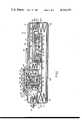
- FIG. 1is a top plan view of implantable infusion apparatus embodying the principles of this invention and for practicing our method;
- FIG. 2is a sectional view along lines 2--2 of FIG. 1;
- FIG. 3is an enlarged sectional view along lines 3--3 of FIG. 2;
- FIG. 4Ais a similar view along lines 4A--4A of FIG. 1;
- FIG. 4Bis a similar view along lines 4B--4B of FIG. 1;
- FIG. 4Cis a similar view along lines 4C--4C of FIG. 1;
- FIG. 5is a diagrammatic view of the infusion apparatus of this invention.
- FIGS. 6A to 6Care graphical illustrations of valve functions and flow rates of the FIG. 5 system
- FIG. 7is a schematic illustration of a modification of the FIG. 5 system.
- FIGS. 8A through 8Care graphical illustrations of flows in the FIG. 7 apparatus.
- the infusion apparatuscomprises a generally cylindrical housing 10 made of stainless steel, titanium or other strong corrosion resistant material.
- housing 10is on the order of three inches in diameter and one inch thick.
- housing 10is composed of a pair of upper and lower cup-like sections 10a and 10b which are secured together at their rims along with the edge 12a of a circular plate 12 which divides the housing into upper and lower compartments 14 and 16. That securement may be accomplished by a circumferential weld bead 18 or by other appropriate means.
- Plate 12forms a header for a bellows capsule 22 situated in compartment 16.
- One end 22a of the bellows capsuleis welded, brazed or otherwise secured to an edge margin of plate 12 just inside the weld head 18.
- the opposite end 22b of the capsuleis closed.
- a circular central portion 12b of plate 12 inside the bellows capsuleis dished downwardly as viewed in FIG. 2. Engagement of that portion by the bellows end wall 22b prevents excessive compression of the bellows which event might cause undue stresses on the capsule.
- the dished portionalso maximizes the volume of housing compartment 14 and minimizes the residual or dead volume of the basal reservoir.
- Capsule 22is preferably a titanium welded metal bellows and its diameter is slightly smaller than housing 10 to maximize the capsule volume, e.g., 20 ml.
- the space inside the capsuleconstitutes the main reservoir for infusate at the basal concentration, e.g., 20-30 units per milliliter.
- a fluid outlet from the confined volume of the capsuleis provided at 24 in plate 12.
- Subassembly 28comprises an inverted cup 32 nested in the top of housing section 10a near one side thereof. Cup 32 is provided with a circular cover 34 whose edge is welded or otherwise secured to the rim of cup 32 to form a closed compartment 36 inside the cup.
- One end 38a of a second or bolus bellows capsule 38is secured to the inside of cover 34 near the outer edge thereof, the opposite capsule end 38b being closed.
- the central portion 34a of cover 34 inside the bellows capsule 38is dished for the same reasons discussed above in connection with cover 12.
- Capsule 38is, like capsule 22, a welded metal bellows, its extended volume being about one-fifth that of capsule 22, e.g. 4 ml.
- the space inside bellows capsule 38is the secondary infusate reservoir that contains the higher concentration infusate suitable for the bolus doses, e.g. 300-400 units per milliliter.
- a fluid outlet from the capsuleis provided through an opening 42 in cover 34.
- the space outside capsule 38, but inside chamber 36contains a two-phase fluid of the type described above in connection with capsule 22. At physiological temperatures that fluid exerts pressure on capsule 38, causing the capsule to collapse and expel its contents through opening 42.
- Subassembly 46Nested between cover portions 12b and 34a is a third or auxiliary reservoir subassembly indicated generally at 46.
- Subassembly 46includes an inverted cup 50 having a generally circular cover 48 welded to its rim.
- a third bellows capsule 52has one end 52a welded or otherwise secured to the inside of cover 50 near its edge and the opposite end 52b of the capsule is closed.
- the space inside capsule 52constitutes an auxiliary reservoir or accumulator for bolus infusate.
- the space outside capsule 52, yet inside cup 50contains a compressible fluid, a spring or a two-phase fluid which, at body temperatures, exerts less pressure on capsule 52 than the similar fluid exerts on capsule 38 but enough to expel infusate into the patient's arterial or venous system.
- Capsule 52is also a welded metal bellows and is quite small, being on the order of one-hundredth the volume of capsule 38, e.g. 0.04 ml.
- a fluid inlet to the capsuleis provided through an opening 56 in a central recessed portion 50a of cover 50 and an outlet from capsule 52 is provided by a passage 58 in the cover near its edge.
- compartment 14also includes a wafer-like filter unit 59 which receives infusate from bellows capsule 22 through a length of tubing 60 connected between capsule outlet 24 and filter inlet 61. All of the connecting tubing in the apparatus is quite small, e.g., 0.012 inch I.D.
- Filter unit 59comprises upper and lower circular shells 59a and 59b whose rims interfit so that the two sections form a cylindrical housing. Inside the housing are a pair of identical circular wafer-like filter support or retainer elements 62a and 62b made of porous stainless steel, titanium or other similar porous material. Sandwiched between the filter retainers is the filter element (not shown) providing filtration to about 0.22 microns. An O-ring 63 encircles element 62b inside shell 59b to provide a seal between the shell and the filter. The two shells are held together by C-clips 64 distributed around the edges of the filter unit 59.
- the filter inlet 61is formed in the bottom wall of shell 59b and the filter outlet 65 is formed in the top wall of shell 59a.
- the infusate from capsule outlet 24flows to a flow restricter 72 in housing compartment 14.
- the restricter 72is simply a length of capillary tubing 74 coiled inside a ring 76, the space in and around the coil being filled with potting material 78.
- the restrictercan be of many configurations. See U.S. Pat. No. 3,951,147.
- the outlet 65 of filter 62is connected by tubing 84 to one end of the coiled capillary tubing 74, the opposite end of the tubing being connected by tubing 86 to a mixing chamber indicated generally at 88 formed in a radially recessed portion 90 in the side wall of housing section 10a as best seen in FIG. 2. From the mixing chamber 88, the infusate is conducted by way of tubing 92 to an infusion site in the patient, the opposite end of tubing 92 being fitted with an appropriate catheter.
- a second filter 102is positioned in housing compartment 14 to receive the bolus infusate from bellows capsule 38. Fluid communication is achieved between those two components by a length of tubing 104 (FIG. 2) extending between the capsule outlet 42 and the filter inlet. Filter 102 is identical to filter 62 illustrated in FIG. 4B and accordingly it will not be detailed. From filter 102, the bolus infusate proceeds to a second flow restricter 106 which is, except for its length perhaps, identical to the restricter 72 illustrated in FIG. 4C. Therefore, we will not describe the restricter 106 in detail. The fluid output from restricter 106 is fed to the auxiliary bellows capsule 52 or accumulator by means of tubing 108 extending between the flow restricter and the capsule inlet 56. Infusate flow out of that capsule is through tubing 110 connected between capsule outlet 58 and a valve assembly mounted in housing compartment 14 and indicated generally at 112.
- the bolus infusateis conducted by tubing 114 containing a flow restricter 116 to mixing chamber 88.
- Restriction 116is present simply for flow definition and smoothening purposes and that function may very well be provided by the regular tubing segment between the valve assembly and the chamber.
- valve assembly 112comprises a generally cylindrical cup 118 which fits in an opening 120 formed in the top of housing section 10a so that a small length of the cup projects out through the top of the opening.
- a circumferential welded seam 122connects the cup to housing section 10a.
- a circular disk 124Positioned at the bottom of cup 118 is a circular disk 124 which supports a relatively heavy coil spring 126, the disk being grooved to center the spring.
- a second, lighter coil spring 128 positioned inside spring 126also rests on disk 124 being centered there by a raised boss 132 on that disk.
- a circular plate 134Seated on the spring 128 inside spring 126 is a circular plate 134 having a central boss 134a projecting down into spring 128.
- Plate 134supports the upper ends of four posts 136 which extend down between springs 126 and 128 and through loose-fitting openings 138 in disk 124.
- a circular plate 142Connected to the lower ends of those parts is a circular plate 142, clearance for the plate being provided by an opening 144 in the bottom wall of cup 118.
- the valve assemblyalso includes an actuating button 146 in the form of an inverted cup which fits down snugly inside cup 118 resting on the upper end of spring 126.
- Button 146has a depending axial nose 146a which projects down into a mating opening 134b in the top of plate 134 to help center the components of the valve assembly.
- a flexible, resilient circular membrane 152is positioned at the rim of cup 118 and retained there by a circular internally threaded ring 154 which is turned down onto external threads 156 on the projecting portion of cup 118.
- Membrane 152provides a resilient impervious seal all around the button.
- the final component of the valve assemblyis a length of flexible resilient tubing 158 made of silastic or other comparable material sandwiched between disk 124 and plate 142.
- One end of the tubingcommunicates with tube 110 leading to the outlet of auxiliary bellows capsule 52.
- the other end of the tubingconnects with the tube 114 leading to the restrictor 116 and mixing chamber 88.
- the flexible tubingis recessed into a groove 124a formed in the underside of disk 124 to maintain the tubing in a centered position in the assembly.
- both springs 126 and 128are extended so that the button is in its uppermost position. In that position, the plate 134, being biased upwardly by spring 128, assumes its uppermost position thereby drawing plate 142 up along with it and squeezing the tubing 158 between plate 142 and disk 124 so that no fluid can flow through the tubing.
- the plates 134 and 142are forced downwardly so that the tubing 158 assumes its normal cylindrical shape allowing fluid to flow from bellows capsule 52 to mixing chamber 88.
- the advantage of utilizing the double spring arrangement illustrated in FIG. 2is that the force which compresses the relatively delicate flexible tubing 158 is provided by the relatively light-weight spring 128.
- the heavy spring 126determines the force required to depress button 146 sufficiently to open the valve. Desirably, the required actuating force should be relatively great so that the valve cannot be opened accidentally. In other words, a single spring could not provide both a relatively small squeezing force on tubing 158 and a relatively great return bias force on button 146.
- a self-sealing penetrable septum assembly shown generally at 162is mounted at one side of housing section 10a through which infusate at the basal concentration can be injected into the apparatus to refill bellows capsule 22.
- a similar assembly indicated generally at 164is located on the opposite side of housing action 10a.
- Both of these septum assembliesare identical so that only the former one is illustrated in detail in FIG. 4A. It comprises a cup 168 positioned in an opening 170 in the top wall of housing section 10a, the rim of the cup projecting above the housing wall. A circumferential weld 171 permanently connects the wall of the cup to the edge of opening 170 inside the housing section. Cup 168 has a relatively large diameter upper section 168a and a smaller diameter lower section 168b defining a cylindrical space 172. An opening 174 is provided in the bottom wall of cup 168 in which is connected one end of a tube 176 which leads to the bellows capsule 22.
- a wafer-like penetrable septum or plugSeated in the cup section 168a is a wafer-like penetrable septum or plug made of rubber or other comparable material.
- the septumis held in place by a ring 180 which is externally threaded so that it can be screwed or pressed down onto the projecting portion of cup 168 which carries internal threads 182.
- a needle stop 183In the bottom of cup 168 is a needle stop 183 such as a wafer or teflon or other plastic material to receive the needle point during refill. Holes through the wafer allow the infusate to exit the chamber.
- a hypodermic needleis pierced through septum 178 so that it projects into chamber 172. Thence the infusate is injected into the chamber 172 whereupon it flows through tube 176 under the injection pressure to the bellows capsule 22. The incoming infusate extends the capsule and thereby compresses the two-phase fluid in housing compartment 16, thereby recharging the power cell that drives that capsule all as described in the aforesaid patents.
- capsule 52is refilled and its power cell recharged by infusate injection through septum 164.
- FIG. 5 of the drawingsis a diagrammatic view showing more clearly the flow paths between the various infusion apparatus components and to the waveforms in FIGS. 6A to 6C depicting the basal, bolus and integrated unit flow rates for the apparatus in operation.
- the basal reservoir 22has been completely filled and charged by injection of infusate in the basal concentration through septum 162.
- the bolus reservoir 38has been filled and charged by injection of the bolus infusate through septum 164.
- Basal infusateflows through filter 59 and flow restrictor 72 to the mixing chamber 88 at a very slow rate, e.g., on the order of 0.6 ml/day, the specific rate depending upon the particular patient's basal insulin requirement. From chamber 88 the infusate proceeds through tubine 92 to the catheter and into the patient's physiological system.
- the infusate from the bolus reservoir 38proceeds through filter 102 and flow restrictor 106 at an even slower rate of about 0.16 ml/day to accumulator 52.
- the incoming infusategradually extends the accumulator in opposition to the gas pressure or spring bias thereon until the accumulator is fully extended in which position it may hold, for example, 0.044 ml, constituting, say, one bolus infusion dose for a particular patient.
- Valve 112being normally closed, prevents infusate flow from accumulator 52 to the mixing chamber 88. Accordingly as seen from FIG. 6A, the patient receives a continuous infusate dose at the basal concentration at a rate of about 0.6 ml/day.
- the patientconsumes a meal at time T m .
- the patient's blood sugar levelnormally tends to rise relatively dramatically so that the basal insulin dosage does not suffice to offset the increased glucose level in patient's bloodstream.
- the patientcan actuate the valve 112 by manually depressing button 146 positioned under the patient's skin.
- the opening of that valvepermits the accumulator 52 to expel its contents through the restrictor 116 to the mixing chamber 88 a relatively high rate for a very short time period, say 320 ml/day for several seconds or a few minutes.
- accumulator 52has a very small volume, it contains infusate in a high concentration presenting a large total bolus dose. Accordingly as seen from FIG. 6B, the dosage rate measured in infusate units per day is quite high, if short-lived, due to the high volumetric flow rate and the high drug concentration from the accumulator to the mixing chamber.
- the bolus infusatemixes with and supplements the basal infusate still arriving from the basal reservoir 22, with the integrated infusate dosage to the patient being reflected in FIG. 6C.
- the integrated flow rateis not simply the instantaneous sum of the basal and bolus rates illustrated in FIGS. 6A and 6B. Rather, it is a more complex function of reservoir volumes, infusate concentrations, flow path resistance, mixing chamber volume, outlet tube volume and valve-on time.
- the segment of the FIG. 6C curve indicated at A denoting the basal infusate flow rateis, of course, a function of the basal infusate concentration and volumetric flow rate through restrictor 72 to the mixing chamber.
- a bolus dose of high concentration infusateis issued to chamber 88 where it mixes with the basal infusate present there so that a short-lived "slug" of high concentration infusate at a high flow rate is dispensed to the patient as indicated by the curve segment C in FIG. 6C.
- the dose rate of infusatedrops to a level that is still higher than the original basal rate, as indicated by the curve segment D in FIG. 6C (since the high volumetric flow rate has ceased, the does is defined by the flow rate of restrictor 72 and the concentration in the bolus reservoir).
- the dose rateremains at that level for a relatively long period indicated which time duration depends upon the volumetric flow rate through restrictor 72 and the volume of liquid in the mixing chamber and the outlet catheter.
- the unit ratefalls back to the original basal rate as the low concentration infusate at the flow rate for restrictor 72 mixes with and reduces the concentration of liquid in the mixing chamber as shown by curve segment E in FIG. 6C.
- the infusion rate peak (because of mixing of basal and bolus concentrations) indicated in FIG. 6Ctrails off more or less in an expotential fashion as indicated by the dotted line curve W 1 in that figure.
- the transition from the higher rate at curve segment D to the basal rate at segment Efalls off expotentially as shown by the dotted line curved W 2 in FIG. 6C.
- the time constants of the curve segments W 1 and W 2can be varied by varying the volume of chamber 88 the differences in drug concentrations and the flow rate through restrictor tube 72.
- the present apparatusas soon as the valve 112 controlling the bolus flow is opened when the need arises, high concentration infusate is immediately dispensed to the patient with minimal system inertia.
- the desired dosage transition from the bolus back down to the basal ratemay vary from patient to patient. For example, in one patient it may take a fairly long time for his glucose level to drop back to its ambient level after a meal due to physiological factors, while another patient may reach his nominal glucose level more quickly.
- the present apparatusis advantaged, then, in that its integrated infusate output to each patient can be tailored to suit his particular needs by proper selection of basal and bolus infusate concentrations mixing chamber and catheter volume, restrictor flow rates and valve actuation time. Accordingly, the apparatus allows great flexibility in prescribing infusate to a patient over a prolonged period.
- the apparatusdispenses high concentration infusate for the bolus doses, the low concentration basal supply is not depleted for that purpose as in prior apparatus of this type.
- the bolus reservoircan have a relatively small volume and the valve-open time of the valve 112 can be quite short thereby conserving energy in the event that an electrically operated valve is employed. Accordingly, the apparatus can remain implanted in the body for a prolonged period, e.g. a year or more, without having to be recharged, with only relatively infrequent, e.g. monthly, infusate refills being required during that period.
- the present apparatusalso protects the patient from inadvertant bolus infusate overdoses in the event that valve 112 is opened repeatedly or is held in the open position. More particularly, each time valve 112 is opened by the patient, the maximum volume of bolus infusate that is dispensed to the patient is the contents of accumulator 52 representing, say, one bolus infusate dose. This is because the flow restrictor 106 between filter 102 and the accumulator is such that the accumulator is refilled from reservoir 38 at an extremely slow rate, e.g. 0.16 ml/day. Accordingly, even if the valve 112 remains open for a long time, e.g., an hour, the patient still receives not much more that one-quarter of the bolus dose of infusate.
- FIG. 7shows such an apparatus employing a single reservoir 270 connected by way of a flow restrictor 272 to a T fitting 274.
- a second flow path leading from reservoir 270communicates with the fitting by way of a valve 276 and flow restrictor 278.
- the T fittingis, in turn, connected by way of a tube 280 to a catheter at the infusion site.
- an accumulator restrictorsuch as accumulator 52 with a restricted inlet can be provided upstream of valve 276 as in the case in the apparatus illustrated in FIG. 5.
- the restrictor 272provides a relatively slow basal flow rate to chamber 274 as indicated by the waveform in FIG. 8A.
- the restrictor 278provides for a much greater or substantially unrestricted bolus flow from reservoir 270 to the fitting 274 when the valve 276 is opened at meal time as indicated by the curve in FIG. 8B.
- the integrated unit dose rate that is dispensed at the infusion siteis represented by the curve in FIG. 8C.
- the present implantable infusion apparatusdispenses infusate in one or more concentrations of one or more types at rates to suit the particular patient's requirements.
- the infusate flow rate characteristicscan be tailored with precision simply by modifying the flow rates and volumes of the apparatus components, particularly the mixing chamber and the apparatus outlet tube. Since the apparatus can dispense infusate in different concentrations, it can supply the patient's basal and bolus requirements in a minimum overall package so that the presence of the apparatus in the body is not unduly discomforting in terms of the space that it occupies in the body or in terms of the frequency with which it must be refilled or recharged.
Landscapes
- Health & Medical Sciences (AREA)
- Vascular Medicine (AREA)
- Engineering & Computer Science (AREA)
- Anesthesiology (AREA)
- Biomedical Technology (AREA)
- Heart & Thoracic Surgery (AREA)
- Hematology (AREA)
- Life Sciences & Earth Sciences (AREA)
- Animal Behavior & Ethology (AREA)
- General Health & Medical Sciences (AREA)
- Public Health (AREA)
- Veterinary Medicine (AREA)
- Infusion, Injection, And Reservoir Apparatuses (AREA)
Abstract
Description
Claims (15)
Priority Applications (2)
| Application Number | Priority Date | Filing Date | Title |
|---|---|---|---|
| US06/009,756US4193397A (en) | 1977-12-01 | 1979-02-05 | Infusion apparatus and method |
| US05/076,169US4258711A (en) | 1979-02-05 | 1979-09-17 | Infusion apparatus and method |
Applications Claiming Priority (2)
| Application Number | Priority Date | Filing Date | Title |
|---|---|---|---|
| US85655877A | 1977-12-01 | 1977-12-01 | |
| US06/009,756US4193397A (en) | 1977-12-01 | 1979-02-05 | Infusion apparatus and method |
Related Parent Applications (1)
| Application Number | Title | Priority Date | Filing Date |
|---|---|---|---|
| US85655877AContinuation-In-Part | 1977-12-01 | 1977-12-01 |
Related Child Applications (1)
| Application Number | Title | Priority Date | Filing Date |
|---|---|---|---|
| US05/076,169DivisionUS4258711A (en) | 1979-02-05 | 1979-09-17 | Infusion apparatus and method |
Publications (1)
| Publication Number | Publication Date |
|---|---|
| US4193397Atrue US4193397A (en) | 1980-03-18 |
Family
ID=26679850
Family Applications (1)
| Application Number | Title | Priority Date | Filing Date |
|---|---|---|---|
| US06/009,756Expired - LifetimeUS4193397A (en) | 1977-12-01 | 1979-02-05 | Infusion apparatus and method |
Country Status (1)
| Country | Link |
|---|---|
| US (1) | US4193397A (en) |
Cited By (180)
| Publication number | Priority date | Publication date | Assignee | Title |
|---|---|---|---|---|
| WO1980001755A1 (en)* | 1979-02-28 | 1980-09-04 | Andros Inc | Implantable infusion device |
| US4258711A (en)* | 1979-02-05 | 1981-03-31 | Metal Bellows Corporation | Infusion apparatus and method |
| EP0039124A1 (en)* | 1980-03-07 | 1981-11-04 | Infusaid Corporation | Implantable infusion apparatus |
| US4299220A (en)* | 1979-05-03 | 1981-11-10 | The Regents Of The University Of Minnesota | Implantable drug infusion regulator |
| US4360019A (en)* | 1979-02-28 | 1982-11-23 | Andros Incorporated | Implantable infusion device |
| DE3316934A1 (en)* | 1982-05-10 | 1983-11-10 | Infusaid Corp., Norwood, Mass. | IMPLANTABLE VALVE |
| DE3321472A1 (en)* | 1982-06-14 | 1983-12-15 | Infusaid Corp., Norwood, Mass. | IMPLANTABLE INFUSION DEVICE |
| US4482346A (en)* | 1982-07-30 | 1984-11-13 | Consolidated Controls Corporation | Apparatus for infusing medication into the body |
| US4496343A (en)* | 1982-06-14 | 1985-01-29 | Infusaid Corporation | Infusate pump |
| US4557726A (en)* | 1982-12-27 | 1985-12-10 | Consolidated Controls Corporation | Precision medication dispensing system and method |
| US4559931A (en)* | 1983-03-21 | 1985-12-24 | Fischell Robert | Manually actuated fully implantable penile erection device |
| USH150H (en) | 1984-08-03 | 1986-11-04 | Medtronic, Inc. | Accessory module for implantable fluid dispensing device |
| US4634424A (en)* | 1984-04-23 | 1987-01-06 | Windsor Medical, Inc. | Multiple re-entry implantable septum and method of using same |
| US4655765A (en)* | 1984-06-01 | 1987-04-07 | Parker Hannifin Corporation | Fitting with prestressed septum |
| US4668231A (en)* | 1984-02-15 | 1987-05-26 | Cordis Corporation | Implantable hand-operable dispensers for fluid medicaments |
| US4695273A (en)* | 1986-04-08 | 1987-09-22 | I-Flow Corporation | Multiple needle holder and subcutaneous multiple channel infusion port |
| US4697622A (en)* | 1984-06-01 | 1987-10-06 | Parker Hannifin Corporation | Passive filling device |
| US4699615A (en)* | 1984-06-21 | 1987-10-13 | Fischell David R | Finger actuated medication infusion system |
| US4802885A (en)* | 1986-06-17 | 1989-02-07 | Medical Engineering Corporation | Self sealing subcutaneous infusion and withdrawal device |
| EP0291612A3 (en)* | 1987-05-20 | 1989-02-22 | Robert Lee Cannon, Iii | Accumulator for use with an implantable pump and implantable pump system including this accumulator |
| US4838887A (en)* | 1987-12-15 | 1989-06-13 | Shiley Infusaid Inc. | Programmable valve pump |
| US4898583A (en)* | 1988-05-18 | 1990-02-06 | Baxter Healthcare Corporation | Implantable patient-activated fluid delivery device and outlet valve therefor |
| US4898585A (en)* | 1988-05-18 | 1990-02-06 | Baxter Healthcare Corporation | Implantable patient-activated fluid delivery device with bolus injection port |
| US4898584A (en)* | 1988-05-18 | 1990-02-06 | Baxter Healthcare Corporation | Implantable patient-activated fluid delivery device |
| WO1989010149A3 (en)* | 1988-04-21 | 1990-02-22 | Therex Corp | Implantable infusion apparatus |
| US4955861A (en)* | 1988-04-21 | 1990-09-11 | Therex Corp. | Dual access infusion and monitoring system |
| EP0347743A3 (en)* | 1988-06-23 | 1990-10-31 | Schloegl Annemarie Gmbh | Septum for implantable devices releasing agents |
| US5053031A (en)* | 1988-03-29 | 1991-10-01 | Baxter International Inc. | Pump infusion system |
| US5158547A (en)* | 1991-04-08 | 1992-10-27 | Medtronic, Inc. | Drug administration device over full protection valve |
| US5205820A (en)* | 1989-06-16 | 1993-04-27 | Science, Incorporated | Fluid delivery apparatus |
| WO1993025262A1 (en) | 1992-06-16 | 1993-12-23 | Infusaid, Inc. | Dual access catheter for implantable pump system |
| US5279558A (en)* | 1989-06-16 | 1994-01-18 | Science Incorporated | Fluid delivery apparatus with an additive |
| US5328460A (en)* | 1991-06-21 | 1994-07-12 | Pacesetter Infusion, Ltd. | Implantable medication infusion pump including self-contained acoustic fault detection apparatus |
| US5336188A (en)* | 1989-06-16 | 1994-08-09 | Science Incorporated | Fluid delivery apparatus having a stored energy source |
| US5443450A (en)* | 1994-04-29 | 1995-08-22 | Medtronic, Inc. | Medication delivery device and method of construction |
| US5445616A (en)* | 1994-04-29 | 1995-08-29 | Medtronic, Inc. | Medication delivery device and method of construction |
| WO1995034333A3 (en)* | 1994-06-03 | 1996-01-18 | Antonio Nicholas F D | Hypodermic fluid dispenser |
| US5527307A (en)* | 1994-04-01 | 1996-06-18 | Minimed Inc. | Implantable medication infusion pump with discharge side port |
| US5551849A (en)* | 1994-04-29 | 1996-09-03 | Medtronic, Inc. | Medication delivery device and method of construction |
| US5575770A (en)* | 1995-04-05 | 1996-11-19 | Therex Corporation | Implantable drug infusion system with safe bolus capability |
| WO1996037253A1 (en)* | 1995-05-26 | 1996-11-28 | Science Incorporated | Fluid delivery apparatus |
| WO1997007840A1 (en)* | 1995-08-22 | 1997-03-06 | Pharmatarget, Inc. | Implantable drug delivery apparatus |
| US5656032A (en)* | 1989-06-16 | 1997-08-12 | Science Incorporated | Fluid delivery apparatus and method of making same |
| US5752930A (en)* | 1995-04-28 | 1998-05-19 | Medtronic, Inc. | Implantable techniques for infusing equal volumes of agents to spaced sites |
| US5779676A (en)* | 1995-10-11 | 1998-07-14 | Science Incorporated | Fluid delivery device with bolus injection site |
| WO1999017749A1 (en)* | 1997-10-02 | 1999-04-15 | Iep Group, Inc. | A micromachined valve for fluid applications |
| WO1999030767A1 (en)* | 1997-12-16 | 1999-06-24 | Science Incorporated | Fluid delivery device with flow indicator and rate control |
| US5957895A (en)* | 1998-02-20 | 1999-09-28 | Becton Dickinson And Company | Low-profile automatic injection device with self-emptying reservoir |
| US5957891A (en)* | 1995-10-11 | 1999-09-28 | Science Incorporated | Fluid delivery device with fill adapter |
| EP1038508A1 (en) | 1999-03-20 | 2000-09-27 | Aesculap AG & Co. KG | Prosthetic patch, method for its manufacture and its use in surgery |
| WO2000066201A1 (en)* | 1999-04-28 | 2000-11-09 | Elfver Sten Olof | Implantable drug delivery system |
| WO2000066202A1 (en)* | 1999-04-28 | 2000-11-09 | Elfver Sten Olof | Implantable drug delivery system |
| FR2795330A1 (en)* | 1999-04-30 | 2000-12-29 | Medtronic Inc | PASSIVE FLOW CONTROL DEVICE FOR AN IMPLANTABLE PUMP |
| US20020040208A1 (en)* | 2000-10-04 | 2002-04-04 | Flaherty J. Christopher | Data collection assembly for patient infusion system |
| US6464671B1 (en) | 1999-04-28 | 2002-10-15 | Sten-Olof Elver | Medical system |
| US6494867B1 (en) | 1999-04-28 | 2002-12-17 | Sten-Olof Elver | Medical device |
| US20030050626A1 (en)* | 2001-09-07 | 2003-03-13 | Gibson Scott R. | Infusion device and inlet structure for same |
| US20030078550A1 (en)* | 2001-10-22 | 2003-04-24 | Williamson Shobha Devi | Implantable pump catheter access port denial device |
| US20030135160A1 (en)* | 2001-09-07 | 2003-07-17 | Medtronic Minimed, Inc. | Infusion device and driving mechanism for same |
| US6595756B2 (en) | 2001-09-07 | 2003-07-22 | Medtronic Minimed, Inc. | Electronic control system and process for electromagnetic pump |
| US20030171738A1 (en)* | 2002-03-06 | 2003-09-11 | Konieczynski David D. | Convection-enhanced drug delivery device and method of use |
| US6635049B1 (en) | 1999-04-30 | 2003-10-21 | Medtronic, Inc. | Drug bolus delivery system |
| US20030208184A1 (en)* | 2000-01-11 | 2003-11-06 | Paul Burke | Implantable, refillable infusion device and spetum replacement kit |
| US20040015131A1 (en)* | 2002-07-16 | 2004-01-22 | Flaherty J. Christopher | Flow restriction system and method for patient infusion device |
| EP1384450A1 (en) | 2002-07-21 | 2004-01-28 | Aesculap Ag | Flat implant for use in surgery |
| WO2003022326A3 (en)* | 2001-09-07 | 2004-03-11 | Medtronic Minimed Inc | Infusion device and driving mechanism for same |
| WO2003090509A3 (en)* | 2002-04-23 | 2004-03-25 | Insulet Corp | Transcutaneous fluid delivery system |
| US20040064096A1 (en)* | 2002-09-30 | 2004-04-01 | Flaherty J. Christopher | Components and methods for patient infusion device |
| US20040064088A1 (en)* | 2002-09-30 | 2004-04-01 | William Gorman | Dispenser components and methods for patient infusion device |
| US20040078028A1 (en)* | 2001-11-09 | 2004-04-22 | Flaherty J. Christopher | Plunger assembly for patient infusion device |
| US20040087894A1 (en)* | 2000-09-08 | 2004-05-06 | Flaherty J. Christopher | Devices, systems and methods for patient infusion |
| US6749587B2 (en) | 2001-02-22 | 2004-06-15 | Insulet Corporation | Modular infusion device and method |
| US20040116866A1 (en)* | 2002-12-17 | 2004-06-17 | William Gorman | Skin attachment apparatus and method for patient infusion device |
| US20040126253A1 (en)* | 2002-12-26 | 2004-07-01 | John Gray | Infusion device and driving mechanism and process for same with actuator for multiple infusion uses |
| US20040127852A1 (en)* | 2002-12-26 | 2004-07-01 | John Gray | Infusion device having piston operated driving mechanism and positive pressure reservoir |
| US20040127844A1 (en)* | 2002-03-01 | 2004-07-01 | Flaherty J. Christopher | Flow condition sensor assembly for patient infusion device |
| US6768425B2 (en) | 2000-12-21 | 2004-07-27 | Insulet Corporation | Medical apparatus remote control and method |
| US20040220551A1 (en)* | 2003-04-30 | 2004-11-04 | Flaherty J. Christopher | Low profile components for patient infusion device |
| US20040220545A1 (en)* | 2002-12-23 | 2004-11-04 | Medtronic, Inc. | Method of delivering drugs to specific regions of the spinal cord |
| US6830558B2 (en) | 2002-03-01 | 2004-12-14 | Insulet Corporation | Flow condition sensor assembly for patient infusion device |
| US20050021005A1 (en)* | 2001-10-12 | 2005-01-27 | Flaherty J. Christopher | Laminated patient infusion device |
| US20050065760A1 (en)* | 2003-09-23 | 2005-03-24 | Robert Murtfeldt | Method for advising patients concerning doses of insulin |
| US20050070875A1 (en)* | 2003-09-30 | 2005-03-31 | Codman & Shurtleff, Inc. | Two-compartment reduced volume infusion pump |
| US20050070847A1 (en)* | 2003-09-29 | 2005-03-31 | Van Erp Wilhelmus Petrus Martinus Maria | Rapid-exchange balloon catheter with hypotube shaft |
| US20050119618A1 (en)* | 2003-04-23 | 2005-06-02 | Gonnelli Robert R. | Hydraulically actuated pump for long duration medicament administration |
| US20050165384A1 (en)* | 2002-02-18 | 2005-07-28 | Danfoss A/S | Device for administering of medication in gluid form |
| US20050171477A1 (en)* | 2002-05-23 | 2005-08-04 | Seedlings Life Science Ventures | Apparatus and method for rapid auto-injection of medication |
| US20050182366A1 (en)* | 2003-04-18 | 2005-08-18 | Insulet Corporation | Method For Visual Output Verification |
| US20050191194A1 (en)* | 2004-02-26 | 2005-09-01 | Falk Theodore J. | Low power electromagnetic pump having internal compliant element |
| US20050235732A1 (en)* | 2002-10-09 | 2005-10-27 | Rush Benjamin M | Fluid delivery device with autocalibration |
| US20050238507A1 (en)* | 2002-04-23 | 2005-10-27 | Insulet Corporation | Fluid delivery device |
| US20050273083A1 (en)* | 2003-03-27 | 2005-12-08 | Lebel Ronald J | Implantable medication delivery device using pressure regulator |
| US20050277912A1 (en)* | 2003-07-16 | 2005-12-15 | Sasha John | Programmable medical drug delivery systems and methods for delivery of multiple fluids and concentrations |
| US20060030838A1 (en)* | 2004-07-02 | 2006-02-09 | Gonnelli Robert R | Methods and devices for delivering GLP-1 and uses thereof |
| US20060034943A1 (en)* | 2003-10-31 | 2006-02-16 | Technology Innovations Llc | Process for treating a biological organism |
| US20060106367A1 (en)* | 2001-06-01 | 2006-05-18 | Massengale Roger D | Large volume bolus device and method |
| US20060178633A1 (en)* | 2005-02-03 | 2006-08-10 | Insulet Corporation | Chassis for fluid delivery device |
| US20060224141A1 (en)* | 2005-03-21 | 2006-10-05 | Abbott Diabetes Care, Inc. | Method and system for providing integrated medication infusion and analyte monitoring system |
| US20060271021A1 (en)* | 2005-05-25 | 2006-11-30 | Palion Medical Corporation | Multi-reservoir implantable pump with patient controlled actuation |
| US20060270983A1 (en)* | 2005-05-26 | 2006-11-30 | Lord Peter C | Implantable Infusion Device With Multiple Controllable Fluid Outlets |
| US20060288125A1 (en)* | 2005-05-23 | 2006-12-21 | Boyd William T | System and method for user space operations for direct I/O between an application instance and an I/O adapter |
| US20070005044A1 (en)* | 2005-05-10 | 2007-01-04 | Palion Medical Corporation | Implantable pump with infinitely variable resistor |
| US20070025890A1 (en)* | 2004-06-15 | 2007-02-01 | Joshi Ashok V | Apparatus and method for administering a therapeutic agent into tissue |
| US20070078380A1 (en)* | 2002-08-12 | 2007-04-05 | Marc Yap | System and method for tension-activated fluid control |
| US20070112328A1 (en)* | 2005-05-10 | 2007-05-17 | Palyon Medical Corporation | Variable flow infusion pump system |
| US20070154363A1 (en)* | 2004-06-15 | 2007-07-05 | Joshi Ashok V | Apparatus and Method For Treating and Dispensing a Material Into Tissue |
| US20070176867A1 (en)* | 2006-01-31 | 2007-08-02 | Abbott Diabetes Care, Inc. | Method and system for providing a fault tolerant display unit in an electronic device |
| US20070185470A1 (en)* | 2006-01-30 | 2007-08-09 | Palion Medical Corporation | Template system for multi-reservoir implantable pump |
| EP1935442A2 (en) | 2003-10-06 | 2008-06-25 | Activeo, LLC | Implantable apparatus for administering a therapeutic agent |
| US20080167650A1 (en)* | 2005-08-01 | 2008-07-10 | Joshi Ashok V | Electrochemical Probe and Method for In Situ Treatment of a Tissue |
| US20080277065A1 (en)* | 2007-05-08 | 2008-11-13 | Brett Moody | Hand-Held Labeling Apparatus Having Accessory Storage |
| US20090068954A1 (en)* | 2005-10-31 | 2009-03-12 | Abbott Diabetes Care, Inc. | Method and apparatus for providing data communication in data monitoring and management systems |
| US20090118711A1 (en)* | 2001-09-07 | 2009-05-07 | Medtronic, Inc. | Reduced-noise implantable infusion device |
| US7559926B1 (en)* | 2003-01-13 | 2009-07-14 | Advanced Neuromodulation Systems, Inc. | Actuation system and method for an implantable infusion pump |
| US20090204062A1 (en)* | 2003-10-06 | 2009-08-13 | Mario Muto | Method for administering a therapeutic agent into tissue |
| US20090227989A1 (en)* | 2008-03-05 | 2009-09-10 | Burke Paul F | Multiple reservoir implantable drug infusion device and method |
| US20090240232A1 (en)* | 2006-03-30 | 2009-09-24 | Vakerutas,Llc | Multi-cartridge fluid delivery device |
| US7620437B2 (en) | 2005-06-03 | 2009-11-17 | Abbott Diabetes Care Inc. | Method and apparatus for providing rechargeable power in data monitoring and management systems |
| EP2138198A1 (en) | 2008-06-27 | 2009-12-30 | Codman Neuro Sciences Sarl | Fluidic capillary chip for regulating drug flow rates of infusion pumps |
| US7658196B2 (en) | 2005-02-24 | 2010-02-09 | Ethicon Endo-Surgery, Inc. | System and method for determining implanted device orientation |
| US7679407B2 (en) | 2003-04-28 | 2010-03-16 | Abbott Diabetes Care Inc. | Method and apparatus for providing peak detection circuitry for data communication systems |
| US20100152714A1 (en)* | 2008-12-15 | 2010-06-17 | Medtronic, Inc. | Air tolerant implantable piston pump |
| US20100174272A1 (en)* | 2009-01-02 | 2010-07-08 | Weiner Alan L | In-situ refillable ophthalmic implant |
| US7756561B2 (en) | 2005-09-30 | 2010-07-13 | Abbott Diabetes Care Inc. | Method and apparatus for providing rechargeable power in data monitoring and management systems |
| US7768408B2 (en) | 2005-05-17 | 2010-08-03 | Abbott Diabetes Care Inc. | Method and system for providing data management in data monitoring system |
| US7775215B2 (en) | 2005-02-24 | 2010-08-17 | Ethicon Endo-Surgery, Inc. | System and method for determining implanted device positioning and obtaining pressure data |
| US7775966B2 (en) | 2005-02-24 | 2010-08-17 | Ethicon Endo-Surgery, Inc. | Non-invasive pressure measurement in a fluid adjustable restrictive device |
| US7844342B2 (en) | 2008-02-07 | 2010-11-30 | Ethicon Endo-Surgery, Inc. | Powering implantable restriction systems using light |
| US7922458B2 (en) | 2002-10-09 | 2011-04-12 | Abbott Diabetes Care Inc. | Variable volume, shape memory actuated insulin dispensing pump |
| US7927270B2 (en) | 2005-02-24 | 2011-04-19 | Ethicon Endo-Surgery, Inc. | External mechanical pressure sensor for gastric band pressure measurements |
| US20110125137A1 (en)* | 2009-11-25 | 2011-05-26 | Medtronic, Inc. | Implantable infusion device |
| US8016744B2 (en) | 2005-02-24 | 2011-09-13 | Ethicon Endo-Surgery, Inc. | External pressure-based gastric band adjustment system and method |
| US8016745B2 (en) | 2005-02-24 | 2011-09-13 | Ethicon Endo-Surgery, Inc. | Monitoring of a food intake restriction device |
| US8034065B2 (en) | 2008-02-26 | 2011-10-11 | Ethicon Endo-Surgery, Inc. | Controlling pressure in adjustable restriction devices |
| US8047811B2 (en) | 2002-10-09 | 2011-11-01 | Abbott Diabetes Care Inc. | Variable volume, shape memory actuated insulin dispensing pump |
| US8057492B2 (en) | 2008-02-12 | 2011-11-15 | Ethicon Endo-Surgery, Inc. | Automatically adjusting band system with MEMS pump |
| US8066629B2 (en) | 2005-02-24 | 2011-11-29 | Ethicon Endo-Surgery, Inc. | Apparatus for adjustment and sensing of gastric band pressure |
| US8100870B2 (en) | 2007-12-14 | 2012-01-24 | Ethicon Endo-Surgery, Inc. | Adjustable height gastric restriction devices and methods |
| US8114055B2 (en) | 2005-05-10 | 2012-02-14 | Palyon Medical (Bvi) Limited | Implantable pump with infinitely variable resistor |
| US8114345B2 (en) | 2008-02-08 | 2012-02-14 | Ethicon Endo-Surgery, Inc. | System and method of sterilizing an implantable medical device |
| US20120053514A1 (en)* | 2010-08-25 | 2012-03-01 | Medtronic, Inc. | Drug infusion device with controllable valve |
| US20120053571A1 (en)* | 2010-08-31 | 2012-03-01 | Medtronic, Inc. | Fluid delivery device with active and passive fluid delivery |
| US20120053562A1 (en)* | 2010-08-25 | 2012-03-01 | Medtronic, Inc. | Fluid delivery device refill access |
| US8142452B2 (en) | 2007-12-27 | 2012-03-27 | Ethicon Endo-Surgery, Inc. | Controlling pressure in adjustable restriction devices |
| US8152710B2 (en) | 2006-04-06 | 2012-04-10 | Ethicon Endo-Surgery, Inc. | Physiological parameter analysis for an implantable restriction device and a data logger |
| US8187162B2 (en) | 2008-03-06 | 2012-05-29 | Ethicon Endo-Surgery, Inc. | Reorientation port |
| US8187163B2 (en) | 2007-12-10 | 2012-05-29 | Ethicon Endo-Surgery, Inc. | Methods for implanting a gastric restriction device |
| US8192350B2 (en) | 2008-01-28 | 2012-06-05 | Ethicon Endo-Surgery, Inc. | Methods and devices for measuring impedance in a gastric restriction system |
| US8221439B2 (en) | 2008-02-07 | 2012-07-17 | Ethicon Endo-Surgery, Inc. | Powering implantable restriction systems using kinetic motion |
| US20120191074A1 (en)* | 2011-01-21 | 2012-07-26 | Palyon Medical (Bvi) Limited | Reduced sized programmable pump |
| US8233995B2 (en) | 2008-03-06 | 2012-07-31 | Ethicon Endo-Surgery, Inc. | System and method of aligning an implantable antenna |
| WO2012112289A3 (en)* | 2011-02-17 | 2012-12-06 | Clifton Alferness | Manual basal bolus drug delivery device |
| US8337389B2 (en) | 2008-01-28 | 2012-12-25 | Ethicon Endo-Surgery, Inc. | Methods and devices for diagnosing performance of a gastric restriction system |
| US8377079B2 (en) | 2007-12-27 | 2013-02-19 | Ethicon Endo-Surgery, Inc. | Constant force mechanisms for regulating restriction devices |
| US20130086982A1 (en)* | 2011-10-07 | 2013-04-11 | Medtronic, Inc. | Ratiometric Plunger Assembly for Volume Sensing Applications |
| US20130096537A1 (en)* | 2011-10-18 | 2013-04-18 | Medtronic Inc. | Implantable infusion device including anti-sealing reservoir |
| US20130103006A1 (en)* | 2011-10-19 | 2013-04-25 | Palyon Medical (Bvi) Limited | Mesh protection system |
| US8467972B2 (en) | 2009-04-28 | 2013-06-18 | Abbott Diabetes Care Inc. | Closed loop blood glucose control algorithm analysis |
| US8560082B2 (en) | 2009-01-30 | 2013-10-15 | Abbott Diabetes Care Inc. | Computerized determination of insulin pump therapy parameters using real time and retrospective data processing |
| US8568360B2 (en) | 2011-12-28 | 2013-10-29 | Palyon Medical (Bvi) Limited | Programmable implantable pump design |
| US8579853B2 (en) | 2006-10-31 | 2013-11-12 | Abbott Diabetes Care Inc. | Infusion devices and methods |
| US8591532B2 (en) | 2008-02-12 | 2013-11-26 | Ethicon Endo-Sugery, Inc. | Automatically adjusting band system |
| US8591395B2 (en) | 2008-01-28 | 2013-11-26 | Ethicon Endo-Surgery, Inc. | Gastric restriction device data handling devices and methods |
| US8591456B2 (en) | 2011-12-28 | 2013-11-26 | Palyon Medical (Bvi) Limited | Multiple reservoir programmable pump |
| US8721605B2 (en) | 2009-04-27 | 2014-05-13 | The Alfred E. Mann Foundation For Scientific Research | Implantable infusion devices with palpable landmarks and methods of needle detection |
| US8798934B2 (en) | 2009-07-23 | 2014-08-05 | Abbott Diabetes Care Inc. | Real time management of data relating to physiological control of glucose levels |
| US8870742B2 (en) | 2006-04-06 | 2014-10-28 | Ethicon Endo-Surgery, Inc. | GUI for an implantable restriction device and a data logger |
| US8915893B2 (en) | 2005-05-10 | 2014-12-23 | Palyon Medical (Bvi) Limited | Variable flow infusion pump system |
| US9211378B2 (en) | 2010-10-22 | 2015-12-15 | Cequr Sa | Methods and systems for dosing a medicament |
| US9953138B2 (en) | 2010-06-29 | 2018-04-24 | Codman Neuro Sciences Sarl | Drug component admixture library for a drug infusion delivery system |
| US10898656B2 (en) | 2017-09-26 | 2021-01-26 | Insulet Corporation | Needle mechanism module for drug delivery device |
| US11045603B2 (en) | 2017-02-22 | 2021-06-29 | Insulet Corporation | Needle insertion mechanisms for drug containers |
| US11090434B2 (en) | 2015-11-24 | 2021-08-17 | Insulet Corporation | Automated drug delivery system |
| US11147931B2 (en) | 2017-11-17 | 2021-10-19 | Insulet Corporation | Drug delivery device with air and backflow elimination |
| US11364341B2 (en) | 2015-11-25 | 2022-06-21 | Insulet Corporation | Wearable medication delivery device |
| US11541015B2 (en) | 2017-05-17 | 2023-01-03 | Massachusetts Institute Of Technology | Self-righting systems, methods, and related components |
| US11607390B2 (en)* | 2017-05-17 | 2023-03-21 | Massachusetts Institute Of Technology | Self-righting systems and related components and methods |
| US11684713B2 (en) | 2012-03-30 | 2023-06-27 | Insulet Corporation | Fluid delivery device, transcutaneous access tool and insertion mechanism for use therewith |
| US12059562B2 (en) | 2018-05-17 | 2024-08-13 | Massachusetts Institute Of Technology | Systems for electrical stimulation |
| US12433512B2 (en) | 2020-12-18 | 2025-10-07 | Insulet Corporation | Adhesive pad with a metallic coil for securing an on-body medical device |
Citations (7)
| Publication number | Priority date | Publication date | Assignee | Title |
|---|---|---|---|---|
| US3840009A (en)* | 1971-12-27 | 1974-10-08 | Alza Corp | Self-powered vapor pressure delivery device |
| US3923060A (en)* | 1974-04-23 | 1975-12-02 | Jr Everett H Ellinwood | Apparatus and method for implanted self-powered medication dispensing having timing and evaluator means |
| US4013074A (en)* | 1974-06-21 | 1977-03-22 | Siposs George G | Implantable medication-dispensing device |
| US4056095A (en)* | 1975-04-04 | 1977-11-01 | Agence Nationale De Valorisation De La Recherche (Anvar) | Control device for medical and surgical uses |
| US4077405A (en)* | 1975-03-26 | 1978-03-07 | Siemens Aktiengesellschaft | Apparatus for infusing liquids into human or animal bodies |
| US4137913A (en)* | 1975-02-28 | 1979-02-06 | Ivac Corporation | Fluid flow control system |
| US4146029A (en)* | 1974-04-23 | 1979-03-27 | Ellinwood Jr Everett H | Self-powered implanted programmable medication system and method |
- 1979
- 1979-02-05USUS06/009,756patent/US4193397A/ennot_activeExpired - Lifetime
Patent Citations (7)
| Publication number | Priority date | Publication date | Assignee | Title |
|---|---|---|---|---|
| US3840009A (en)* | 1971-12-27 | 1974-10-08 | Alza Corp | Self-powered vapor pressure delivery device |
| US3923060A (en)* | 1974-04-23 | 1975-12-02 | Jr Everett H Ellinwood | Apparatus and method for implanted self-powered medication dispensing having timing and evaluator means |
| US4146029A (en)* | 1974-04-23 | 1979-03-27 | Ellinwood Jr Everett H | Self-powered implanted programmable medication system and method |
| US4013074A (en)* | 1974-06-21 | 1977-03-22 | Siposs George G | Implantable medication-dispensing device |
| US4137913A (en)* | 1975-02-28 | 1979-02-06 | Ivac Corporation | Fluid flow control system |
| US4077405A (en)* | 1975-03-26 | 1978-03-07 | Siemens Aktiengesellschaft | Apparatus for infusing liquids into human or animal bodies |
| US4056095A (en)* | 1975-04-04 | 1977-11-01 | Agence Nationale De Valorisation De La Recherche (Anvar) | Control device for medical and surgical uses |
Cited By (350)
| Publication number | Priority date | Publication date | Assignee | Title |
|---|---|---|---|---|
| US4258711A (en)* | 1979-02-05 | 1981-03-31 | Metal Bellows Corporation | Infusion apparatus and method |
| WO1980001755A1 (en)* | 1979-02-28 | 1980-09-04 | Andros Inc | Implantable infusion device |
| US4360019A (en)* | 1979-02-28 | 1982-11-23 | Andros Incorporated | Implantable infusion device |
| US4299220A (en)* | 1979-05-03 | 1981-11-10 | The Regents Of The University Of Minnesota | Implantable drug infusion regulator |
| EP0039124A1 (en)* | 1980-03-07 | 1981-11-04 | Infusaid Corporation | Implantable infusion apparatus |
| DE3316934A1 (en)* | 1982-05-10 | 1983-11-10 | Infusaid Corp., Norwood, Mass. | IMPLANTABLE VALVE |
| FR2528313A1 (en)* | 1982-06-14 | 1983-12-16 | Infusaid Corp | IMPROVEMENT TO A INFUSION PUMP |
| DE3321472A1 (en)* | 1982-06-14 | 1983-12-15 | Infusaid Corp., Norwood, Mass. | IMPLANTABLE INFUSION DEVICE |
| US4496343A (en)* | 1982-06-14 | 1985-01-29 | Infusaid Corporation | Infusate pump |
| US4482346A (en)* | 1982-07-30 | 1984-11-13 | Consolidated Controls Corporation | Apparatus for infusing medication into the body |
| US4557726A (en)* | 1982-12-27 | 1985-12-10 | Consolidated Controls Corporation | Precision medication dispensing system and method |
| US4559931A (en)* | 1983-03-21 | 1985-12-24 | Fischell Robert | Manually actuated fully implantable penile erection device |
| US4668231A (en)* | 1984-02-15 | 1987-05-26 | Cordis Corporation | Implantable hand-operable dispensers for fluid medicaments |
| US4634424A (en)* | 1984-04-23 | 1987-01-06 | Windsor Medical, Inc. | Multiple re-entry implantable septum and method of using same |
| US4697622A (en)* | 1984-06-01 | 1987-10-06 | Parker Hannifin Corporation | Passive filling device |
| US4655765A (en)* | 1984-06-01 | 1987-04-07 | Parker Hannifin Corporation | Fitting with prestressed septum |
| US4699615A (en)* | 1984-06-21 | 1987-10-13 | Fischell David R | Finger actuated medication infusion system |
| USH150H (en) | 1984-08-03 | 1986-11-04 | Medtronic, Inc. | Accessory module for implantable fluid dispensing device |
| US4695273A (en)* | 1986-04-08 | 1987-09-22 | I-Flow Corporation | Multiple needle holder and subcutaneous multiple channel infusion port |
| US4802885A (en)* | 1986-06-17 | 1989-02-07 | Medical Engineering Corporation | Self sealing subcutaneous infusion and withdrawal device |
| EP0291612A3 (en)* | 1987-05-20 | 1989-02-22 | Robert Lee Cannon, Iii | Accumulator for use with an implantable pump and implantable pump system including this accumulator |
| US4813951A (en)* | 1987-05-20 | 1989-03-21 | Joel Wall | Self-actuated implantable pump |
| US4838887A (en)* | 1987-12-15 | 1989-06-13 | Shiley Infusaid Inc. | Programmable valve pump |
| US5053031A (en)* | 1988-03-29 | 1991-10-01 | Baxter International Inc. | Pump infusion system |
| US4978338A (en)* | 1988-04-21 | 1990-12-18 | Therex Corp. | Implantable infusion apparatus |
| WO1989010149A3 (en)* | 1988-04-21 | 1990-02-22 | Therex Corp | Implantable infusion apparatus |
| US4955861A (en)* | 1988-04-21 | 1990-09-11 | Therex Corp. | Dual access infusion and monitoring system |
| AU628054B2 (en)* | 1988-04-21 | 1992-09-10 | Therex Corporation | Implantable infusion apparatus |
| EP0612535B2 (en)† | 1988-04-21 | 2008-05-14 | CODMAN & SHURTLEFF, INC. | Implantable infusion apparatus |
| US4898584A (en)* | 1988-05-18 | 1990-02-06 | Baxter Healthcare Corporation | Implantable patient-activated fluid delivery device |
| US4898583A (en)* | 1988-05-18 | 1990-02-06 | Baxter Healthcare Corporation | Implantable patient-activated fluid delivery device and outlet valve therefor |
| US4898585A (en)* | 1988-05-18 | 1990-02-06 | Baxter Healthcare Corporation | Implantable patient-activated fluid delivery device with bolus injection port |
| EP0347743A3 (en)* | 1988-06-23 | 1990-10-31 | Schloegl Annemarie Gmbh | Septum for implantable devices releasing agents |
| US5205820A (en)* | 1989-06-16 | 1993-04-27 | Science, Incorporated | Fluid delivery apparatus |
| US5656032A (en)* | 1989-06-16 | 1997-08-12 | Science Incorporated | Fluid delivery apparatus and method of making same |
| US5279558A (en)* | 1989-06-16 | 1994-01-18 | Science Incorporated | Fluid delivery apparatus with an additive |
| US5336188A (en)* | 1989-06-16 | 1994-08-09 | Science Incorporated | Fluid delivery apparatus having a stored energy source |
| US5906592A (en)* | 1989-06-16 | 1999-05-25 | Science Incorporated | Fluid delivery apparatus |
| US5716343A (en)* | 1989-06-16 | 1998-02-10 | Science Incorporated | Fluid delivery apparatus |
| US5158547A (en)* | 1991-04-08 | 1992-10-27 | Medtronic, Inc. | Drug administration device over full protection valve |
| US5328460A (en)* | 1991-06-21 | 1994-07-12 | Pacesetter Infusion, Ltd. | Implantable medication infusion pump including self-contained acoustic fault detection apparatus |
| WO1993025262A1 (en) | 1992-06-16 | 1993-12-23 | Infusaid, Inc. | Dual access catheter for implantable pump system |
| WO1994027669A1 (en)* | 1993-05-28 | 1994-12-08 | Science Incorporated | Fluid delivery apparatus |
| US5527307A (en)* | 1994-04-01 | 1996-06-18 | Minimed Inc. | Implantable medication infusion pump with discharge side port |
| US5443450A (en)* | 1994-04-29 | 1995-08-22 | Medtronic, Inc. | Medication delivery device and method of construction |
| US5551849A (en)* | 1994-04-29 | 1996-09-03 | Medtronic, Inc. | Medication delivery device and method of construction |
| US5445616A (en)* | 1994-04-29 | 1995-08-29 | Medtronic, Inc. | Medication delivery device and method of construction |
| WO1995034333A3 (en)* | 1994-06-03 | 1996-01-18 | Antonio Nicholas F D | Hypodermic fluid dispenser |
| US5575770A (en)* | 1995-04-05 | 1996-11-19 | Therex Corporation | Implantable drug infusion system with safe bolus capability |
| US5752930A (en)* | 1995-04-28 | 1998-05-19 | Medtronic, Inc. | Implantable techniques for infusing equal volumes of agents to spaced sites |
| WO1996037253A1 (en)* | 1995-05-26 | 1996-11-28 | Science Incorporated | Fluid delivery apparatus |
| WO1997007840A1 (en)* | 1995-08-22 | 1997-03-06 | Pharmatarget, Inc. | Implantable drug delivery apparatus |
| US5779676A (en)* | 1995-10-11 | 1998-07-14 | Science Incorporated | Fluid delivery device with bolus injection site |
| US5921962A (en)* | 1995-10-11 | 1999-07-13 | Science Incorporated | Fluid delivery device with flow indicator and rate control |
| US5957891A (en)* | 1995-10-11 | 1999-09-28 | Science Incorporated | Fluid delivery device with fill adapter |
| WO1999017749A1 (en)* | 1997-10-02 | 1999-04-15 | Iep Group, Inc. | A micromachined valve for fluid applications |
| WO1999030767A1 (en)* | 1997-12-16 | 1999-06-24 | Science Incorporated | Fluid delivery device with flow indicator and rate control |
| US5957895A (en)* | 1998-02-20 | 1999-09-28 | Becton Dickinson And Company | Low-profile automatic injection device with self-emptying reservoir |
| EP1038508A1 (en) | 1999-03-20 | 2000-09-27 | Aesculap AG & Co. KG | Prosthetic patch, method for its manufacture and its use in surgery |
| EP1570806A2 (en) | 1999-03-20 | 2005-09-07 | Aesculap AG & Co. KG | Prosthetic patch, method for its manufacture and its use in surgery |
| US6447551B1 (en) | 1999-03-20 | 2002-09-10 | Aesculap Ag & Co. Kg | Flat implant, process for its production and use in surgery |
| US6494867B1 (en) | 1999-04-28 | 2002-12-17 | Sten-Olof Elver | Medical device |
| WO2000066201A1 (en)* | 1999-04-28 | 2000-11-09 | Elfver Sten Olof | Implantable drug delivery system |
| US6464671B1 (en) | 1999-04-28 | 2002-10-15 | Sten-Olof Elver | Medical system |
| WO2000066202A1 (en)* | 1999-04-28 | 2000-11-09 | Elfver Sten Olof | Implantable drug delivery system |
| US6471675B1 (en) | 1999-04-30 | 2002-10-29 | Medtronic, Inc. | Passive flow control devices for implantable pumps |
| FR2795330A1 (en)* | 1999-04-30 | 2000-12-29 | Medtronic Inc | PASSIVE FLOW CONTROL DEVICE FOR AN IMPLANTABLE PUMP |
| US6635049B1 (en) | 1999-04-30 | 2003-10-21 | Medtronic, Inc. | Drug bolus delivery system |
| US6979315B2 (en) | 1999-04-30 | 2005-12-27 | Medtronic, Inc. | Passive flow control devices for implantable pumps |
| US7108686B2 (en) | 2000-01-11 | 2006-09-19 | Bard Access Systems, Inc. | Implantable, refillable infusion device and septum replacement kit |
| US20030208184A1 (en)* | 2000-01-11 | 2003-11-06 | Paul Burke | Implantable, refillable infusion device and spetum replacement kit |
| US20040249363A1 (en)* | 2000-01-11 | 2004-12-09 | Bard Access Systems, Inc. | Implantable, refillable infusion device and septum replacement kit |
| US6764472B1 (en) | 2000-01-11 | 2004-07-20 | Bard Access Systems, Inc. | Implantable refillable infusion device |
| US7137964B2 (en) | 2000-09-08 | 2006-11-21 | Insulet Corporation | Devices, systems and methods for patient infusion |
| US20050171512A1 (en)* | 2000-09-08 | 2005-08-04 | Insulet Corporation | Devices, systems and methods for patient infusion |
| US7029455B2 (en) | 2000-09-08 | 2006-04-18 | Insulet Corporation | Devices, systems and methods for patient infusion |
| US20040087894A1 (en)* | 2000-09-08 | 2004-05-06 | Flaherty J. Christopher | Devices, systems and methods for patient infusion |
| US20020040208A1 (en)* | 2000-10-04 | 2002-04-04 | Flaherty J. Christopher | Data collection assembly for patient infusion system |
| US6768425B2 (en) | 2000-12-21 | 2004-07-27 | Insulet Corporation | Medical apparatus remote control and method |
| US6749587B2 (en) | 2001-02-22 | 2004-06-15 | Insulet Corporation | Modular infusion device and method |
| US20060106367A1 (en)* | 2001-06-01 | 2006-05-18 | Massengale Roger D | Large volume bolus device and method |
| US7815604B2 (en)* | 2001-06-01 | 2010-10-19 | I-Flow Corporation | Large volume bolus device and method |
| US7186236B2 (en) | 2001-09-07 | 2007-03-06 | Medtronic Minimed, Inc. | Infusion device and inlet structure for same |
| WO2003022326A3 (en)* | 2001-09-07 | 2004-03-11 | Medtronic Minimed Inc | Infusion device and driving mechanism for same |
| US8696631B2 (en) | 2001-09-07 | 2014-04-15 | Medtronic Minimed, Inc. | Infusion device and driving mechanism for same |
| US6595756B2 (en) | 2001-09-07 | 2003-07-22 | Medtronic Minimed, Inc. | Electronic control system and process for electromagnetic pump |
| US20050240167A1 (en)* | 2001-09-07 | 2005-10-27 | Medtronic Minimed, Inc. | Infusion device and driving mechanism for same |
| US20050159714A1 (en)* | 2001-09-07 | 2005-07-21 | Metronic Minimed, Inc. | Infusion device and inlet structure for same |
| US20030050626A1 (en)* | 2001-09-07 | 2003-03-13 | Gibson Scott R. | Infusion device and inlet structure for same |
| US6770067B2 (en) | 2001-09-07 | 2004-08-03 | Medtronic Minimed, Inc. | Infusion device and driving mechanism for same |
| US6997921B2 (en) | 2001-09-07 | 2006-02-14 | Medtronic Minimed, Inc. | Infusion device and driving mechanism for same |
| US7785293B2 (en) | 2001-09-07 | 2010-08-31 | Medtronic Minimed, Inc. | Infusion device and driving mechanism for same |
| US20050245907A1 (en)* | 2001-09-07 | 2005-11-03 | Medtronic Minimed, Inc. | Infusion device and driving mechanism for same |
| US7628776B2 (en) | 2001-09-07 | 2009-12-08 | Medtronic Minimed, Inc. | Infusion device and inlet structure for same |
| US20030135160A1 (en)* | 2001-09-07 | 2003-07-17 | Medtronic Minimed, Inc. | Infusion device and driving mechanism for same |
| US7396353B2 (en) | 2001-09-07 | 2008-07-08 | Medtronic Minimed, Inc. | Infusion device and driving mechanism for same |
| US20040225281A1 (en)* | 2001-09-07 | 2004-11-11 | Medtronic Minimed, Inc. | Infusion device and driving mechanism for same |
| US20050245908A1 (en)* | 2001-09-07 | 2005-11-03 | Medtronic Minimed, Inc. | Infusion device and driving mechanism for same |
| US7131967B2 (en) | 2001-09-07 | 2006-11-07 | Medtronic Minimed, Inc. | Infusion device and driving mechanism for same |
| US20090118711A1 (en)* | 2001-09-07 | 2009-05-07 | Medtronic, Inc. | Reduced-noise implantable infusion device |
| US20050021005A1 (en)* | 2001-10-12 | 2005-01-27 | Flaherty J. Christopher | Laminated patient infusion device |
| US6663609B2 (en)* | 2001-10-22 | 2003-12-16 | Medtronic, Inc. | Implantable pump catheter access port denial device |
| US20030078550A1 (en)* | 2001-10-22 | 2003-04-24 | Williamson Shobha Devi | Implantable pump catheter access port denial device |
| US20040078028A1 (en)* | 2001-11-09 | 2004-04-22 | Flaherty J. Christopher | Plunger assembly for patient infusion device |
| US7517335B2 (en) | 2002-02-18 | 2009-04-14 | Cequr Aps | Device for administering of medication in fluid form |
| US8945064B2 (en) | 2002-02-18 | 2015-02-03 | Cequr Sa | Device for administering of medication in fluid form |
| US20050165384A1 (en)* | 2002-02-18 | 2005-07-28 | Danfoss A/S | Device for administering of medication in gluid form |
| US6830558B2 (en) | 2002-03-01 | 2004-12-14 | Insulet Corporation | Flow condition sensor assembly for patient infusion device |
| US20040127844A1 (en)* | 2002-03-01 | 2004-07-01 | Flaherty J. Christopher | Flow condition sensor assembly for patient infusion device |
| US7887505B2 (en) | 2002-03-01 | 2011-02-15 | Insulet Corporation | Flow condition sensor assembly for patient infusion device |
| US20080125759A1 (en)* | 2002-03-06 | 2008-05-29 | Codman & Shurtleff, Inc. | Convection-enhanced drug delivery device and method of use |
| US20030171738A1 (en)* | 2002-03-06 | 2003-09-11 | Konieczynski David D. | Convection-enhanced drug delivery device and method of use |
| WO2003090509A3 (en)* | 2002-04-23 | 2004-03-25 | Insulet Corp | Transcutaneous fluid delivery system |
| US20050238507A1 (en)* | 2002-04-23 | 2005-10-27 | Insulet Corporation | Fluid delivery device |
| US7303549B2 (en) | 2002-04-23 | 2007-12-04 | Insulet Corporation | Transcutaneous fluid delivery system |
| US6960192B1 (en) | 2002-04-23 | 2005-11-01 | Insulet Corporation | Transcutaneous fluid delivery system |
| US6979316B1 (en) | 2002-05-23 | 2005-12-27 | Seedlings Life Science Ventures Llc | Apparatus and method for rapid auto-injection of medication |
| US7658724B2 (en) | 2002-05-23 | 2010-02-09 | Seedings Life Science Ventures LLC | Apparatus and method for rapid auto-injection of medication |
| US20050171477A1 (en)* | 2002-05-23 | 2005-08-04 | Seedlings Life Science Ventures | Apparatus and method for rapid auto-injection of medication |
| US20040015131A1 (en)* | 2002-07-16 | 2004-01-22 | Flaherty J. Christopher | Flow restriction system and method for patient infusion device |
| US7018360B2 (en) | 2002-07-16 | 2006-03-28 | Insulet Corporation | Flow restriction system and method for patient infusion device |
| US20060041229A1 (en)* | 2002-07-16 | 2006-02-23 | Insulet Corporation | Flow restriction system and method for patient infusion device |
| EP1384450A1 (en) | 2002-07-21 | 2004-01-28 | Aesculap Ag | Flat implant for use in surgery |
| US20090182265A1 (en)* | 2002-08-12 | 2009-07-16 | Lma North America, Inc | Medication infusion system and method |
| US20070078380A1 (en)* | 2002-08-12 | 2007-04-05 | Marc Yap | System and method for tension-activated fluid control |
| US7527608B2 (en) | 2002-08-12 | 2009-05-05 | Lma North America, Inc. | Medication infusion and aspiration system and method |
| US7520871B2 (en) | 2002-08-12 | 2009-04-21 | Lma North America, Inc | System and method for tension-activated fluid control |
| US7128727B2 (en) | 2002-09-30 | 2006-10-31 | Flaherty J Christopher | Components and methods for patient infusion device |
| US20040064096A1 (en)* | 2002-09-30 | 2004-04-01 | Flaherty J. Christopher | Components and methods for patient infusion device |
| US20040064088A1 (en)* | 2002-09-30 | 2004-04-01 | William Gorman | Dispenser components and methods for patient infusion device |
| US7144384B2 (en) | 2002-09-30 | 2006-12-05 | Insulet Corporation | Dispenser components and methods for patient infusion device |
| US20090182276A1 (en)* | 2002-10-09 | 2009-07-16 | Abbott Diabetes Care, Inc. | Fluid Delivery Device with Autocalibration |
| US8343093B2 (en) | 2002-10-09 | 2013-01-01 | Abbott Diabetes Care Inc. | Fluid delivery device with autocalibration |
| US7753873B2 (en)* | 2002-10-09 | 2010-07-13 | Abbott Diabetes Care Inc. | Fluid delivery device with autocalibration |
| US7727181B2 (en) | 2002-10-09 | 2010-06-01 | Abbott Diabetes Care Inc. | Fluid delivery device with autocalibration |
| US7766864B2 (en)* | 2002-10-09 | 2010-08-03 | Abbott Diabetes Care Inc. | Fluid delivery device with autocalibration |
| US20090177160A1 (en)* | 2002-10-09 | 2009-07-09 | Abbott Diabetes Care, Inc. | Fluid Delivery Device with Autocalibration |
| US20090179044A1 (en)* | 2002-10-09 | 2009-07-16 | Abbott Diabetes Care, Inc. | Fluid Delivery Device with Autocalibration |
| US8047811B2 (en) | 2002-10-09 | 2011-11-01 | Abbott Diabetes Care Inc. | Variable volume, shape memory actuated insulin dispensing pump |
| US20050235732A1 (en)* | 2002-10-09 | 2005-10-27 | Rush Benjamin M | Fluid delivery device with autocalibration |
| US7753874B2 (en)* | 2002-10-09 | 2010-07-13 | Abbott Diabetes Care Inc. | Fluid delivery device with autocalibration |
| US7922458B2 (en) | 2002-10-09 | 2011-04-12 | Abbott Diabetes Care Inc. | Variable volume, shape memory actuated insulin dispensing pump |
| US8047812B2 (en) | 2002-10-09 | 2011-11-01 | Abbott Diabetes Care Inc. | Variable volume, shape memory actuated insulin dispensing pump |
| US7993108B2 (en) | 2002-10-09 | 2011-08-09 | Abbott Diabetes Care Inc. | Variable volume, shape memory actuated insulin dispensing pump |
| US7993109B2 (en) | 2002-10-09 | 2011-08-09 | Abbott Diabetes Care Inc. | Variable volume, shape memory actuated insulin dispensing pump |
| US8029250B2 (en) | 2002-10-09 | 2011-10-04 | Abbott Diabetes Care Inc. | Variable volume, shape memory actuated insulin dispensing pump |
| US8029245B2 (en) | 2002-10-09 | 2011-10-04 | Abbott Diabetes Care Inc. | Variable volume, shape memory actuated insulin dispensing pump |
| US20040116866A1 (en)* | 2002-12-17 | 2004-06-17 | William Gorman | Skin attachment apparatus and method for patient infusion device |
| US20040220518A1 (en)* | 2002-12-23 | 2004-11-04 | Medtronic, Inc. | Drug solution density adjustment systems and methods |
| US20040220552A1 (en)* | 2002-12-23 | 2004-11-04 | Medtronic, Inc. | Implantable drug delivery systems and methods |
| US20040220543A1 (en)* | 2002-12-23 | 2004-11-04 | Medtronic, Inc. | Trailing system for evaluation of the efficacy of the treatment |
| US8216177B2 (en)* | 2002-12-23 | 2012-07-10 | Medtronic, Inc. | Implantable drug delivery systems and methods |
| US20040220546A1 (en)* | 2002-12-23 | 2004-11-04 | Medtronic, Inc. | Reduction of inflammatory mass with spinal catheters |
| US8137334B2 (en) | 2002-12-23 | 2012-03-20 | Medtronic, Inc. | Reduction of inflammatory mass with spinal catheters |
| US7662140B2 (en) | 2002-12-23 | 2010-02-16 | Medtronic, Inc. | Method of delivering drug to brain via spinal cord |
| US20040220545A1 (en)* | 2002-12-23 | 2004-11-04 | Medtronic, Inc. | Method of delivering drugs to specific regions of the spinal cord |
| US6932584B2 (en) | 2002-12-26 | 2005-08-23 | Medtronic Minimed, Inc. | Infusion device and driving mechanism and process for same with actuator for multiple infusion uses |
| US20050024175A1 (en)* | 2002-12-26 | 2005-02-03 | Medtronic Minimed, Inc. | Infusion device and driving mechanism and process for same with actuator for multiple infusion uses |
| US20060056998A1 (en)* | 2002-12-26 | 2006-03-16 | Medtronic Minimed, Inc. | Infusion device and driving mechanism and process for same with actuator for multiple infusion uses |
| US7762793B2 (en) | 2002-12-26 | 2010-07-27 | Medtronic Minimed, Inc. | Infusion device and driving mechanism and process for same with actuator for multiple infusion uses |
| US20040126253A1 (en)* | 2002-12-26 | 2004-07-01 | John Gray | Infusion device and driving mechanism and process for same with actuator for multiple infusion uses |
| US20040127852A1 (en)* | 2002-12-26 | 2004-07-01 | John Gray | Infusion device having piston operated driving mechanism and positive pressure reservoir |
| US7255690B2 (en) | 2002-12-26 | 2007-08-14 | Medtronic Minimed, Inc. | Infusion device having piston operated driving mechanism and positive pressure reservoir |
| US6945760B2 (en) | 2002-12-26 | 2005-09-20 | Medtronic Minimed, Inc. | Infusion device and driving mechanism and process for same with actuator for multiple infusion uses |
| US7559926B1 (en)* | 2003-01-13 | 2009-07-14 | Advanced Neuromodulation Systems, Inc. | Actuation system and method for an implantable infusion pump |
| US20050273083A1 (en)* | 2003-03-27 | 2005-12-08 | Lebel Ronald J | Implantable medication delivery device using pressure regulator |
| US7510552B2 (en) | 2003-03-27 | 2009-03-31 | Infusion Systems, Llc | Implantable medication delivery device using pressure regulator |
| US20050182366A1 (en)* | 2003-04-18 | 2005-08-18 | Insulet Corporation | Method For Visual Output Verification |
| US7530968B2 (en) | 2003-04-23 | 2009-05-12 | Valeritas, Inc. | Hydraulically actuated pump for long duration medicament administration |
| US9072828B2 (en) | 2003-04-23 | 2015-07-07 | Valeritas, Inc. | Hydraulically actuated pump for long duration medicament administration |
| US11642456B2 (en) | 2003-04-23 | 2023-05-09 | Mannkind Corporation | Hydraulically actuated pump for fluid administration |
| US9511187B2 (en) | 2003-04-23 | 2016-12-06 | Valeritas, Inc. | Hydraulically actuated pump for fluid administration |
| US20050119618A1 (en)* | 2003-04-23 | 2005-06-02 | Gonnelli Robert R. | Hydraulically actuated pump for long duration medicament administration |
| US10525194B2 (en) | 2003-04-23 | 2020-01-07 | Valeritas, Inc. | Hydraulically actuated pump for fluid administration |
| US20100217191A1 (en)* | 2003-04-23 | 2010-08-26 | Valeritas, Inc. | Hydraulically actuated pump for fluid administration |
| US9125983B2 (en) | 2003-04-23 | 2015-09-08 | Valeritas, Inc. | Hydraulically actuated pump for fluid administration |
| US8070726B2 (en) | 2003-04-23 | 2011-12-06 | Valeritas, Inc. | Hydraulically actuated pump for long duration medicament administration |
| US8512246B2 (en) | 2003-04-28 | 2013-08-20 | Abbott Diabetes Care Inc. | Method and apparatus for providing peak detection circuitry for data communication systems |
| US7679407B2 (en) | 2003-04-28 | 2010-03-16 | Abbott Diabetes Care Inc. | Method and apparatus for providing peak detection circuitry for data communication systems |
| US20040220551A1 (en)* | 2003-04-30 | 2004-11-04 | Flaherty J. Christopher | Low profile components for patient infusion device |
| US20050277912A1 (en)* | 2003-07-16 | 2005-12-15 | Sasha John | Programmable medical drug delivery systems and methods for delivery of multiple fluids and concentrations |
| US7811279B2 (en)* | 2003-07-16 | 2010-10-12 | Sasha John | Programmable medical drug delivery systems and methods for delivery of multiple fluids and concentrations |
| US20050065760A1 (en)* | 2003-09-23 | 2005-03-24 | Robert Murtfeldt | Method for advising patients concerning doses of insulin |
| US20050070847A1 (en)* | 2003-09-29 | 2005-03-31 | Van Erp Wilhelmus Petrus Martinus Maria | Rapid-exchange balloon catheter with hypotube shaft |
| EP1520595A1 (en)* | 2003-09-30 | 2005-04-06 | CODMAN & SHURTLEFF, INC. | Two-compartment reduced volume infusion pump |
| EP1797917A3 (en)* | 2003-09-30 | 2007-07-04 | CODMAN & SHURTLEFF, INC. | Two-compartement reduced volume infusion pump |
| US7896865B2 (en)* | 2003-09-30 | 2011-03-01 | Codman & Shurtleff, Inc. | Two-compartment reduced volume infusion pump |
| JP2005103273A (en)* | 2003-09-30 | 2005-04-21 | Codman & Shurtleff Inc | Medication infusion apparatus and infusion method |
| US20050070875A1 (en)* | 2003-09-30 | 2005-03-31 | Codman & Shurtleff, Inc. | Two-compartment reduced volume infusion pump |
| US8066695B2 (en) | 2003-10-06 | 2011-11-29 | Ceramatec, Inc. | Implantable apparatus for administering a therapeutic agent into tissue |
| US20090209902A1 (en)* | 2003-10-06 | 2009-08-20 | Mario Muto | Kit for adminstering a therapeutic agent into tissue |
| US8162873B2 (en) | 2003-10-06 | 2012-04-24 | Ceramatec, Inc. | Apparatus for administering a therapeutic agent into tissue |
| US20090209901A1 (en)* | 2003-10-06 | 2009-08-20 | Mario Muto | Apparatus for adminstering a therapeutic agent into tissue |
| US20090204062A1 (en)* | 2003-10-06 | 2009-08-13 | Mario Muto | Method for administering a therapeutic agent into tissue |
| US20090254021A1 (en)* | 2003-10-06 | 2009-10-08 | Mario Muto | Kit for administering a therapeutic agent into tissue |
| EP1935442A3 (en)* | 2003-10-06 | 2008-07-02 | Activeo, LLC | Implantable apparatus for administering a therapeutic agent |
| EP1935442A2 (en) | 2003-10-06 | 2008-06-25 | Activeo, LLC | Implantable apparatus for administering a therapeutic agent |
| US20060034943A1 (en)* | 2003-10-31 | 2006-02-16 | Technology Innovations Llc | Process for treating a biological organism |
| US20050191194A1 (en)* | 2004-02-26 | 2005-09-01 | Falk Theodore J. | Low power electromagnetic pump having internal compliant element |
| US8777889B2 (en) | 2004-06-15 | 2014-07-15 | Ceramatec, Inc. | Apparatus and method for administering a therapeutic agent into tissue |
| US20070025890A1 (en)* | 2004-06-15 | 2007-02-01 | Joshi Ashok V | Apparatus and method for administering a therapeutic agent into tissue |
| US8591472B2 (en) | 2004-06-15 | 2013-11-26 | Ceramatec, Inc. | Apparatus for administering a therapeutic agent into tissue using a needle as the material treatment module |
| US8066659B2 (en) | 2004-06-15 | 2011-11-29 | Ceramatec, Inc. | Apparatus and method for treating and dispensing a material into tissue |
| US20070154363A1 (en)* | 2004-06-15 | 2007-07-05 | Joshi Ashok V | Apparatus and Method For Treating and Dispensing a Material Into Tissue |
| US8986520B2 (en) | 2004-06-15 | 2015-03-24 | Ceramatec, Inc. | Apparatus administering a therapeutic agent into tissue |
| US20100307928A1 (en)* | 2004-06-15 | 2010-12-09 | Joshi Ashok V | Apparatus and method for administering a therapeutic agent into tissue |
| US20100312171A1 (en)* | 2004-06-15 | 2010-12-09 | Joshi Ashok V | Apparatus and method for administering a therapeutic agent into tissue |
| US9089636B2 (en) | 2004-07-02 | 2015-07-28 | Valeritas, Inc. | Methods and devices for delivering GLP-1 and uses thereof |
| US20060030838A1 (en)* | 2004-07-02 | 2006-02-09 | Gonnelli Robert R | Methods and devices for delivering GLP-1 and uses thereof |
| US20090182307A1 (en)* | 2004-07-30 | 2009-07-16 | Lma North America, Inc. | System and Method for Tension-Activated Fluid Control |
| US20060178633A1 (en)* | 2005-02-03 | 2006-08-10 | Insulet Corporation | Chassis for fluid delivery device |
| US8016745B2 (en) | 2005-02-24 | 2011-09-13 | Ethicon Endo-Surgery, Inc. | Monitoring of a food intake restriction device |
| US7927270B2 (en) | 2005-02-24 | 2011-04-19 | Ethicon Endo-Surgery, Inc. | External mechanical pressure sensor for gastric band pressure measurements |
| US7775215B2 (en) | 2005-02-24 | 2010-08-17 | Ethicon Endo-Surgery, Inc. | System and method for determining implanted device positioning and obtaining pressure data |
| US8016744B2 (en) | 2005-02-24 | 2011-09-13 | Ethicon Endo-Surgery, Inc. | External pressure-based gastric band adjustment system and method |
| US8066629B2 (en) | 2005-02-24 | 2011-11-29 | Ethicon Endo-Surgery, Inc. | Apparatus for adjustment and sensing of gastric band pressure |
| US7658196B2 (en) | 2005-02-24 | 2010-02-09 | Ethicon Endo-Surgery, Inc. | System and method for determining implanted device orientation |
| US7775966B2 (en) | 2005-02-24 | 2010-08-17 | Ethicon Endo-Surgery, Inc. | Non-invasive pressure measurement in a fluid adjustable restrictive device |
| US8343092B2 (en) | 2005-03-21 | 2013-01-01 | Abbott Diabetes Care Inc. | Method and system for providing integrated medication infusion and analyte monitoring system |
| US8029460B2 (en) | 2005-03-21 | 2011-10-04 | Abbott Diabetes Care Inc. | Method and system for providing integrated medication infusion and analyte monitoring system |
| US20100100076A1 (en)* | 2005-03-21 | 2010-04-22 | Abbott Diabetes Care Inc. | Method and System for Providing Integrated Medication Infusion and Analyte Monitoring System |
| US8029459B2 (en) | 2005-03-21 | 2011-10-04 | Abbott Diabetes Care Inc. | Method and system for providing integrated medication infusion and analyte monitoring system |
| US20060224141A1 (en)* | 2005-03-21 | 2006-10-05 | Abbott Diabetes Care, Inc. | Method and system for providing integrated medication infusion and analyte monitoring system |
| US8114055B2 (en) | 2005-05-10 | 2012-02-14 | Palyon Medical (Bvi) Limited | Implantable pump with infinitely variable resistor |
| US7637892B2 (en) | 2005-05-10 | 2009-12-29 | Palyon Medical (Bvi) Limited | Variable flow infusion pump system |
| US8915893B2 (en) | 2005-05-10 | 2014-12-23 | Palyon Medical (Bvi) Limited | Variable flow infusion pump system |
| US8177750B2 (en) | 2005-05-10 | 2012-05-15 | Palyon Medical (Bvi) Limited | Variable flow infusion pump system |
| US20070005044A1 (en)* | 2005-05-10 | 2007-01-04 | Palion Medical Corporation | Implantable pump with infinitely variable resistor |
| US20070112328A1 (en)* | 2005-05-10 | 2007-05-17 | Palyon Medical Corporation | Variable flow infusion pump system |
| US20100069892A1 (en)* | 2005-05-10 | 2010-03-18 | Palyon Medical (Bvi) Limited | Variable flow infusion pump system |
| US8591478B2 (en) | 2005-05-10 | 2013-11-26 | Palyon Medical (Bvi) Limited | Reduced size implantable pump |
| US8211060B2 (en) | 2005-05-10 | 2012-07-03 | Palyon Medical (Bvi) Limited | Reduced size implantable pump |
| US8471714B2 (en) | 2005-05-17 | 2013-06-25 | Abbott Diabetes Care Inc. | Method and system for providing data management in data monitoring system |
| US8089363B2 (en) | 2005-05-17 | 2012-01-03 | Abbott Diabetes Care Inc. | Method and system for providing data management in data monitoring system |
| US9332944B2 (en) | 2005-05-17 | 2016-05-10 | Abbott Diabetes Care Inc. | Method and system for providing data management in data monitoring system |
| US9750440B2 (en) | 2005-05-17 | 2017-09-05 | Abbott Diabetes Care Inc. | Method and system for providing data management in data monitoring system |
| US10206611B2 (en) | 2005-05-17 | 2019-02-19 | Abbott Diabetes Care Inc. | Method and system for providing data management in data monitoring system |
| US8653977B2 (en) | 2005-05-17 | 2014-02-18 | Abbott Diabetes Care Inc. | Method and system for providing data management in data monitoring system |
| US7884729B2 (en) | 2005-05-17 | 2011-02-08 | Abbott Diabetes Care Inc. | Method and system for providing data management in data monitoring system |
| US7768408B2 (en) | 2005-05-17 | 2010-08-03 | Abbott Diabetes Care Inc. | Method and system for providing data management in data monitoring system |
| US20060288125A1 (en)* | 2005-05-23 | 2006-12-21 | Boyd William T | System and method for user space operations for direct I/O between an application instance and an I/O adapter |
| US8034029B2 (en) | 2005-05-25 | 2011-10-11 | Palyon Medical (Bvi) Limited | Multi-reservoir implantable pump with patient controlled actuation |
| US8034030B2 (en) | 2005-05-25 | 2011-10-11 | Palyon Medical (Bvi) Limited | Multi-reservoir implantable pump with variable flow rate capabilities |
| US20060271021A1 (en)* | 2005-05-25 | 2006-11-30 | Palion Medical Corporation | Multi-reservoir implantable pump with patient controlled actuation |
| US20060271022A1 (en)* | 2005-05-25 | 2006-11-30 | Palion Medical Corporation | Multi-reservoir implantable pump with variable flow rate capabilities |
| US20060270983A1 (en)* | 2005-05-26 | 2006-11-30 | Lord Peter C | Implantable Infusion Device With Multiple Controllable Fluid Outlets |
| US8002747B2 (en) | 2005-05-26 | 2011-08-23 | The Alfred E. Mann Foundation For Scientific Research | Implantable infusion device with multiple controllable fluid outlets |
| US8808243B2 (en) | 2005-05-26 | 2014-08-19 | Medallion Therapeutics, Inc. | Implantable infusion device with multiple controllable fluid outlets |
| EP2050476A3 (en)* | 2005-05-26 | 2009-09-16 | Infusion Systems, LLC | Implantable infusion device with multiple controllable fluid outlets |
| US8112138B2 (en) | 2005-06-03 | 2012-02-07 | Abbott Diabetes Care Inc. | Method and apparatus for providing rechargeable power in data monitoring and management systems |
| US7620437B2 (en) | 2005-06-03 | 2009-11-17 | Abbott Diabetes Care Inc. | Method and apparatus for providing rechargeable power in data monitoring and management systems |
| US8353906B2 (en) | 2005-08-01 | 2013-01-15 | Ceramatec, Inc. | Electrochemical probe and method for in situ treatment of a tissue |
| US20080167650A1 (en)* | 2005-08-01 | 2008-07-10 | Joshi Ashok V | Electrochemical Probe and Method for In Situ Treatment of a Tissue |
| US7756561B2 (en) | 2005-09-30 | 2010-07-13 | Abbott Diabetes Care Inc. | Method and apparatus for providing rechargeable power in data monitoring and management systems |
| US7583190B2 (en) | 2005-10-31 | 2009-09-01 | Abbott Diabetes Care Inc. | Method and apparatus for providing data communication in data monitoring and management systems |
| US20090068954A1 (en)* | 2005-10-31 | 2009-03-12 | Abbott Diabetes Care, Inc. | Method and apparatus for providing data communication in data monitoring and management systems |
| US7948370B2 (en) | 2005-10-31 | 2011-05-24 | Abbott Diabetes Care Inc. | Method and apparatus for providing data communication in data monitoring and management systems |
| US8638220B2 (en) | 2005-10-31 | 2014-01-28 | Abbott Diabetes Care Inc. | Method and apparatus for providing data communication in data monitoring and management systems |
| US20070185470A1 (en)* | 2006-01-30 | 2007-08-09 | Palion Medical Corporation | Template system for multi-reservoir implantable pump |
| US20100160859A1 (en)* | 2006-01-30 | 2010-06-24 | Palyon Medical (Bvi) Limited | Template system for multi-reservoir implantable pump |
| US7708730B2 (en) | 2006-01-30 | 2010-05-04 | Palyon Medical (Bvi) Limited | Template system for multi-reservoir implantable pump |
| US7914510B2 (en) | 2006-01-30 | 2011-03-29 | Palyon Medical (Bvi) Limited | Template system for multi-reservoir implantable pump |
| US20070176867A1 (en)* | 2006-01-31 | 2007-08-02 | Abbott Diabetes Care, Inc. | Method and system for providing a fault tolerant display unit in an electronic device |
| US8344966B2 (en) | 2006-01-31 | 2013-01-01 | Abbott Diabetes Care Inc. | Method and system for providing a fault tolerant display unit in an electronic device |
| US8361053B2 (en) | 2006-03-30 | 2013-01-29 | Valeritas, Inc. | Multi-cartridge fluid delivery device |
| US9687599B2 (en) | 2006-03-30 | 2017-06-27 | Valeritas, Inc. | Multi-cartridge fluid delivery device |
| US7914499B2 (en) | 2006-03-30 | 2011-03-29 | Valeritas, Inc. | Multi-cartridge fluid delivery device |
| US12246159B2 (en) | 2006-03-30 | 2025-03-11 | Mannkind Corporation | Multi-cartridge fluid delivery device |
| US20110137287A1 (en)* | 2006-03-30 | 2011-06-09 | Valeritas, Inc. | Multi-cartridge fluid delivery device |
| US8821443B2 (en) | 2006-03-30 | 2014-09-02 | Valeritas, Inc. | Multi-cartridge fluid delivery device |
| US20090240232A1 (en)* | 2006-03-30 | 2009-09-24 | Vakerutas,Llc | Multi-cartridge fluid delivery device |
| US10493199B2 (en) | 2006-03-30 | 2019-12-03 | Valeritas, Inc. | Multi-cartridge fluid delivery device |
| US8152710B2 (en) | 2006-04-06 | 2012-04-10 | Ethicon Endo-Surgery, Inc. | Physiological parameter analysis for an implantable restriction device and a data logger |
| US8870742B2 (en) | 2006-04-06 | 2014-10-28 | Ethicon Endo-Surgery, Inc. | GUI for an implantable restriction device and a data logger |
| US12073941B2 (en) | 2006-10-31 | 2024-08-27 | Abbott Diabetes Care Inc. | Infusion device and methods |
| US11508476B2 (en) | 2006-10-31 | 2022-11-22 | Abbott Diabetes Care, Inc. | Infusion devices and methods |
| US9064107B2 (en) | 2006-10-31 | 2015-06-23 | Abbott Diabetes Care Inc. | Infusion devices and methods |
| US11043300B2 (en) | 2006-10-31 | 2021-06-22 | Abbott Diabetes Care Inc. | Infusion devices and methods |
| US8579853B2 (en) | 2006-10-31 | 2013-11-12 | Abbott Diabetes Care Inc. | Infusion devices and methods |
| US11837358B2 (en) | 2006-10-31 | 2023-12-05 | Abbott Diabetes Care Inc. | Infusion devices and methods |
| US10007759B2 (en) | 2006-10-31 | 2018-06-26 | Abbott Diabetes Care Inc. | Infusion devices and methods |
| US20080277065A1 (en)* | 2007-05-08 | 2008-11-13 | Brett Moody | Hand-Held Labeling Apparatus Having Accessory Storage |
| US8187163B2 (en) | 2007-12-10 | 2012-05-29 | Ethicon Endo-Surgery, Inc. | Methods for implanting a gastric restriction device |
| US8100870B2 (en) | 2007-12-14 | 2012-01-24 | Ethicon Endo-Surgery, Inc. | Adjustable height gastric restriction devices and methods |
| US8142452B2 (en) | 2007-12-27 | 2012-03-27 | Ethicon Endo-Surgery, Inc. | Controlling pressure in adjustable restriction devices |
| US8377079B2 (en) | 2007-12-27 | 2013-02-19 | Ethicon Endo-Surgery, Inc. | Constant force mechanisms for regulating restriction devices |
| US8337389B2 (en) | 2008-01-28 | 2012-12-25 | Ethicon Endo-Surgery, Inc. | Methods and devices for diagnosing performance of a gastric restriction system |
| US8192350B2 (en) | 2008-01-28 | 2012-06-05 | Ethicon Endo-Surgery, Inc. | Methods and devices for measuring impedance in a gastric restriction system |
| US8591395B2 (en) | 2008-01-28 | 2013-11-26 | Ethicon Endo-Surgery, Inc. | Gastric restriction device data handling devices and methods |
| US7844342B2 (en) | 2008-02-07 | 2010-11-30 | Ethicon Endo-Surgery, Inc. | Powering implantable restriction systems using light |
| US8221439B2 (en) | 2008-02-07 | 2012-07-17 | Ethicon Endo-Surgery, Inc. | Powering implantable restriction systems using kinetic motion |
| US8114345B2 (en) | 2008-02-08 | 2012-02-14 | Ethicon Endo-Surgery, Inc. | System and method of sterilizing an implantable medical device |
| US8591532B2 (en) | 2008-02-12 | 2013-11-26 | Ethicon Endo-Sugery, Inc. | Automatically adjusting band system |
| US8057492B2 (en) | 2008-02-12 | 2011-11-15 | Ethicon Endo-Surgery, Inc. | Automatically adjusting band system with MEMS pump |
| US8034065B2 (en) | 2008-02-26 | 2011-10-11 | Ethicon Endo-Surgery, Inc. | Controlling pressure in adjustable restriction devices |
| US20090227989A1 (en)* | 2008-03-05 | 2009-09-10 | Burke Paul F | Multiple reservoir implantable drug infusion device and method |
| US20100089487A1 (en)* | 2008-03-05 | 2010-04-15 | Burke Paul F | Multiple reservoir implantable drug infusion device and method |
| US8545477B2 (en) | 2008-03-05 | 2013-10-01 | Flowonix Medical Incorporated | Multiple reservoir implantable drug infusion device and method |
| US8551044B2 (en)* | 2008-03-05 | 2013-10-08 | Flowonix Medical Incorporated | Multiple reservoir implantable drug infusion device and method |
| US8233995B2 (en) | 2008-03-06 | 2012-07-31 | Ethicon Endo-Surgery, Inc. | System and method of aligning an implantable antenna |
| US8187162B2 (en) | 2008-03-06 | 2012-05-29 | Ethicon Endo-Surgery, Inc. | Reorientation port |
| EP2138198A1 (en) | 2008-06-27 | 2009-12-30 | Codman Neuro Sciences Sarl | Fluidic capillary chip for regulating drug flow rates of infusion pumps |
| US20090326517A1 (en)* | 2008-06-27 | 2009-12-31 | Toralf Bork | Fluidic capillary chip for regulating drug flow rates of infusion pumps |
| US9968733B2 (en) | 2008-12-15 | 2018-05-15 | Medtronic, Inc. | Air tolerant implantable piston pump |
| US20100152714A1 (en)* | 2008-12-15 | 2010-06-17 | Medtronic, Inc. | Air tolerant implantable piston pump |
| US20100174272A1 (en)* | 2009-01-02 | 2010-07-08 | Weiner Alan L | In-situ refillable ophthalmic implant |
| US8560082B2 (en) | 2009-01-30 | 2013-10-15 | Abbott Diabetes Care Inc. | Computerized determination of insulin pump therapy parameters using real time and retrospective data processing |
| US8721605B2 (en) | 2009-04-27 | 2014-05-13 | The Alfred E. Mann Foundation For Scientific Research | Implantable infusion devices with palpable landmarks and methods of needle detection |
| US9981117B2 (en) | 2009-04-27 | 2018-05-29 | Medallion Therapeutics, Inc. | Implantable infusion devices and associated methods |
| US8467972B2 (en) | 2009-04-28 | 2013-06-18 | Abbott Diabetes Care Inc. | Closed loop blood glucose control algorithm analysis |
| US8798934B2 (en) | 2009-07-23 | 2014-08-05 | Abbott Diabetes Care Inc. | Real time management of data relating to physiological control of glucose levels |
| US10872102B2 (en) | 2009-07-23 | 2020-12-22 | Abbott Diabetes Care Inc. | Real time management of data relating to physiological control of glucose levels |
| US9259530B2 (en) | 2009-11-25 | 2016-02-16 | Medtronic, Inc. | Implantable infusion device |
| US20110125137A1 (en)* | 2009-11-25 | 2011-05-26 | Medtronic, Inc. | Implantable infusion device |
| US9953138B2 (en) | 2010-06-29 | 2018-04-24 | Codman Neuro Sciences Sarl | Drug component admixture library for a drug infusion delivery system |
| US20120053562A1 (en)* | 2010-08-25 | 2012-03-01 | Medtronic, Inc. | Fluid delivery device refill access |
| US10143796B2 (en)* | 2010-08-25 | 2018-12-04 | Medtronic, Inc. | Fluid delivery device refill access |
| US11285258B2 (en) | 2010-08-25 | 2022-03-29 | Medtronic, Inc. | Fluid delivery device refill access |
| US20120053514A1 (en)* | 2010-08-25 | 2012-03-01 | Medtronic, Inc. | Drug infusion device with controllable valve |
| US9737660B2 (en)* | 2010-08-25 | 2017-08-22 | Medtronic, Inc. | Drug infusion device with controllable valve |
| US20120053571A1 (en)* | 2010-08-31 | 2012-03-01 | Medtronic, Inc. | Fluid delivery device with active and passive fluid delivery |
| US9211378B2 (en) | 2010-10-22 | 2015-12-15 | Cequr Sa | Methods and systems for dosing a medicament |
| US20120191074A1 (en)* | 2011-01-21 | 2012-07-26 | Palyon Medical (Bvi) Limited | Reduced sized programmable pump |
| RU2608622C2 (en)* | 2011-02-17 | 2017-01-23 | Калибра Медикал, Инк. | Manual device for basal bolus drug delivery |
| WO2012112289A3 (en)* | 2011-02-17 | 2012-12-06 | Clifton Alferness | Manual basal bolus drug delivery device |
| US8561460B2 (en)* | 2011-10-07 | 2013-10-22 | Medtronic, Inc. | Ratiometric plunger assembly for volume sensing applications |
| US20130086982A1 (en)* | 2011-10-07 | 2013-04-11 | Medtronic, Inc. | Ratiometric Plunger Assembly for Volume Sensing Applications |
| US9278176B2 (en) | 2011-10-07 | 2016-03-08 | Medtronic, Inc. | Dual plunger based systems and method for use in determining a volume in a reservoir |
| US10010667B2 (en)* | 2011-10-18 | 2018-07-03 | Medtronic, Inc. | Implantable infusion device including anti-sealing reservoir |
| US20130096537A1 (en)* | 2011-10-18 | 2013-04-18 | Medtronic Inc. | Implantable infusion device including anti-sealing reservoir |
| US20130103006A1 (en)* | 2011-10-19 | 2013-04-25 | Palyon Medical (Bvi) Limited | Mesh protection system |
| US8568360B2 (en) | 2011-12-28 | 2013-10-29 | Palyon Medical (Bvi) Limited | Programmable implantable pump design |
| US8591456B2 (en) | 2011-12-28 | 2013-11-26 | Palyon Medical (Bvi) Limited | Multiple reservoir programmable pump |
| US8808231B2 (en) | 2011-12-28 | 2014-08-19 | Palyon Medical (Bvi) Limited | Multiple reservoir programmable pump |
| US8961466B2 (en) | 2011-12-28 | 2015-02-24 | Palyon Medical (Bvi) Limited | Programmable implantable pump design |
| US12329928B2 (en) | 2012-03-30 | 2025-06-17 | Insulet Corporation | Fluid delivery device, transcutaneous access tool and fluid drive mechanism for use therewith |
| US11684713B2 (en) | 2012-03-30 | 2023-06-27 | Insulet Corporation | Fluid delivery device, transcutaneous access tool and insertion mechanism for use therewith |
| US11090434B2 (en) | 2015-11-24 | 2021-08-17 | Insulet Corporation | Automated drug delivery system |
| US11744944B2 (en) | 2015-11-24 | 2023-09-05 | Insulet Corporation | Wearable automated medication delivery system |
| US11364341B2 (en) | 2015-11-25 | 2022-06-21 | Insulet Corporation | Wearable medication delivery device |
| US11045603B2 (en) | 2017-02-22 | 2021-06-29 | Insulet Corporation | Needle insertion mechanisms for drug containers |
| US11607390B2 (en)* | 2017-05-17 | 2023-03-21 | Massachusetts Institute Of Technology | Self-righting systems and related components and methods |
| US11541015B2 (en) | 2017-05-17 | 2023-01-03 | Massachusetts Institute Of Technology | Self-righting systems, methods, and related components |
| US11712421B2 (en) | 2017-05-17 | 2023-08-01 | Massachusetts Institute Of Technology | Self-actuating articles |
| US12064520B2 (en) | 2017-05-17 | 2024-08-20 | Massachusetts Institute Of Technology | Components with high API loading |
| US12268832B2 (en) | 2017-05-17 | 2025-04-08 | Massachusetts Institute Of Technology | Self-righting systems, methods, and related components |
| US10898656B2 (en) | 2017-09-26 | 2021-01-26 | Insulet Corporation | Needle mechanism module for drug delivery device |
| US11147931B2 (en) | 2017-11-17 | 2021-10-19 | Insulet Corporation | Drug delivery device with air and backflow elimination |
| US12059562B2 (en) | 2018-05-17 | 2024-08-13 | Massachusetts Institute Of Technology | Systems for electrical stimulation |
| US12433512B2 (en) | 2020-12-18 | 2025-10-07 | Insulet Corporation | Adhesive pad with a metallic coil for securing an on-body medical device |
Similar Documents
| Publication | Publication Date | Title |
|---|---|---|
| US4193397A (en) | Infusion apparatus and method | |
| US4258711A (en) | Infusion apparatus and method | |
| US20210308367A1 (en) | Flexible and conformal patch pump | |
| US5053031A (en) | Pump infusion system | |
| US4447224A (en) | Variable flow implantable infusion apparatus | |
| US4360019A (en) | Implantable infusion device | |
| US4221219A (en) | Implantable infusion apparatus and method | |
| US8771227B2 (en) | Constant rate fluid delivery device with selectable flow rate and titratable bolus button | |
| US4781688A (en) | Dispensing device for a liquid medicament | |
| EP0998317B1 (en) | Inlet port for a medication infusion pump | |
| CA1262325A (en) | Pressure regulated implantable infusion pump | |
| US4443218A (en) | Programmable implantable infusate pump | |
| US4077405A (en) | Apparatus for infusing liquids into human or animal bodies | |
| US4838887A (en) | Programmable valve pump | |
| US8628517B2 (en) | Micro-fluidic device for drug delivery | |
| EP0612535B1 (en) | Implantable infusion apparatus | |
| AU724234B2 (en) | Fluid delivery device with conformable ullage and fill assembly | |
| EP0039124B1 (en) | Implantable infusion apparatus | |
| JP2001515371A (en) | Drug delivery device with bolus injection site | |
| US20050267422A1 (en) | Fluid delivery apparatus | |
| WO2014159866A1 (en) | Dual rate insulin pump | |
| CA1333144C (en) | Implantable drug delivery system | |
| EP0143503B1 (en) | Implantable hand-operable dispensers for fluid medicaments |
Legal Events
| Date | Code | Title | Description |
|---|---|---|---|
| AS | Assignment | Owner name:INFUSAID CORPORATION, 1075 PROVIDENCE HIGHWAY, SHA Free format text:ASSIGNMENT OF ASSIGNORS INTEREST.;ASSIGNOR:METAL BELLOWS CORPORATION;REEL/FRAME:003829/0450 Effective date:19810121 | |
| AS | Assignment | Owner name:INTERMEDICS INFUSAID, INC., 1400 PROVIDENCE HIGHWA Free format text:ASSIGNMENT OF ASSIGNORS INTEREST.;ASSIGNOR:INFUSAID CORPORATION, BY: CLINTON T. CROLIUS, TRUSTEE OFTHE INFUSAID LIQUIDATING TRUST, SUCCESSOR TO THE ASSETS OF INFUSAID CORPORATION;REEL/FRAME:004880/0090 Effective date:19861010 Owner name:SHILEY INFUSAID, INC., HALE & DORR, 60 STATE STREE Free format text:ASSIGNMENT OF ASSIGNORS INTEREST.;ASSIGNOR:INTERMEDICS INFUSAID, INC., A TX CORP.;REEL/FRAME:004880/0098 Effective date:19861010 Owner name:INTERMEDICS INFUSAID, INC., A CORP. OF TEXAS,MASSA Free format text:ASSIGNMENT OF ASSIGNORS INTEREST;ASSIGNOR:INFUSAID CORPORATION, BY: CLINTON T. CROLIUS, TRUSTEE OF THE INFUSAID LIQUIDATING TRUST, SUCCESSOR TO THE ASSETS OF INFUSAID CORPORATION;REEL/FRAME:004880/0090 Effective date:19861010 Owner name:SHILEY INFUSAID, INC.,MASSACHUSETTS Free format text:ASSIGNMENT OF ASSIGNORS INTEREST;ASSIGNOR:INTERMEDICS INFUSAID, INC., A TX CORP.;REEL/FRAME:004880/0098 Effective date:19861010 |