US4191246A - Device to reduce local heat flux through a heat exchanger tube - Google Patents
Device to reduce local heat flux through a heat exchanger tubeDownload PDFInfo
- Publication number
- US4191246A US4191246AUS06/017,649US1764979AUS4191246AUS 4191246 AUS4191246 AUS 4191246AUS 1764979 AUS1764979 AUS 1764979AUS 4191246 AUS4191246 AUS 4191246A
- Authority
- US
- United States
- Prior art keywords
- tube
- heat exchanger
- shell
- support means
- insulating sleeve
- Prior art date
- Legal status (The legal status is an assumption and is not a legal conclusion. Google has not performed a legal analysis and makes no representation as to the accuracy of the status listed.)
- Expired - Lifetime
Links
- 230000004907fluxEffects0.000titleabstractdescription6
- XLYOFNOQVPJJNP-UHFFFAOYSA-NwaterSubstancesOXLYOFNOQVPJJNP-UHFFFAOYSA-N0.000claimsabstractdescription17
- 239000012530fluidSubstances0.000claimsdescription20
- 238000010438heat treatmentMethods0.000claimsdescription4
- 230000004888barrier functionEffects0.000claimsdescription3
- 239000007788liquidSubstances0.000claimsdescription2
- 238000011144upstream manufacturingMethods0.000claims1
- 239000007787solidSubstances0.000abstractdescription10
- 238000010025steamingMethods0.000abstract1
- 230000008020evaporationEffects0.000description6
- 238000001704evaporationMethods0.000description6
- 239000002184metalSubstances0.000description3
- 238000000034methodMethods0.000description3
- 238000009825accumulationMethods0.000description2
- 238000005260corrosionMethods0.000description2
- 230000007797corrosionEffects0.000description2
- 230000008021depositionEffects0.000description2
- 239000007791liquid phaseSubstances0.000description2
- 238000001556precipitationMethods0.000description2
- 230000001133accelerationEffects0.000description1
- 238000009835boilingMethods0.000description1
- 230000003467diminishing effectEffects0.000description1
- 229910001055inconels 600Inorganic materials0.000description1
- 238000009413insulationMethods0.000description1
- 239000000203mixtureSubstances0.000description1
- 230000003068static effectEffects0.000description1
Images
Classifications
- F—MECHANICAL ENGINEERING; LIGHTING; HEATING; WEAPONS; BLASTING
- F28—HEAT EXCHANGE IN GENERAL
- F28F—DETAILS OF HEAT-EXCHANGE AND HEAT-TRANSFER APPARATUS, OF GENERAL APPLICATION
- F28F19/00—Preventing the formation of deposits or corrosion, e.g. by using filters or scrapers
- F28F19/002—Preventing the formation of deposits or corrosion, e.g. by using filters or scrapers by using inserts or attachments
- F—MECHANICAL ENGINEERING; LIGHTING; HEATING; WEAPONS; BLASTING
- F22—STEAM GENERATION
- F22B—METHODS OF STEAM GENERATION; STEAM BOILERS
- F22B1/00—Methods of steam generation characterised by form of heating method
- F22B1/02—Methods of steam generation characterised by form of heating method by exploitation of the heat content of hot heat carriers
- F22B1/023—Methods of steam generation characterised by form of heating method by exploitation of the heat content of hot heat carriers with heating tubes for nuclear reactors, as long as they are not classified according to a specified heating fluid, in another group
- F—MECHANICAL ENGINEERING; LIGHTING; HEATING; WEAPONS; BLASTING
- F22—STEAM GENERATION
- F22B—METHODS OF STEAM GENERATION; STEAM BOILERS
- F22B37/00—Component parts or details of steam boilers
- F22B37/02—Component parts or details of steam boilers applicable to more than one kind or type of steam boiler
- F22B37/10—Water tubes; Accessories therefor
- F22B37/18—Inserts, e.g. for receiving deposits from water
- F—MECHANICAL ENGINEERING; LIGHTING; HEATING; WEAPONS; BLASTING
- F22—STEAM GENERATION
- F22B—METHODS OF STEAM GENERATION; STEAM BOILERS
- F22B37/00—Component parts or details of steam boilers
- F22B37/02—Component parts or details of steam boilers applicable to more than one kind or type of steam boiler
- F22B37/10—Water tubes; Accessories therefor
- F22B37/20—Supporting arrangements, e.g. for securing water-tube sets
- F22B37/205—Supporting and spacing arrangements for tubes of a tube bundle
Definitions
- tube supportsare used to minimize tube vibration induced by the fluid flowing on the shell side of the exchanger.
- These tube supportsmay be drilled plates, machined plates with various clearances around the tube or lattice supports built from metal strips or bars.
- crevicesthere exists areas of tight clearance between the tube and support which can be referred to as crevices.
- the shell side fluidwhich is the fluid being heated, in flowing through the crevices is partially or wholly evaporated by the heat transferred from the tube side fluid to the shell side fluid.
- the crevice formed by a tube and the supportis especially vulnerable to high solids deposition due to part or total evaporation of the water as it flows through the crevice.
- the solids accumulation in the creviceis undesirable, as it can lead to complete blockage of flow through the crevice, which increases shell side pressure drop, and may induce localized tube corrosion or other phenomena which could reduce the service life of such tube.
- a flow distribution plate 46(FIGS. 1 and 5) is located above the tube sheet 18. This plate is for the purpose of distributing the flow more equally across the entire cross-section of the shell.
- a distribution plateit may be desirable to minimize the heat flux in the entire space between the tube sheet and the distribution plate, in addition to the crevices between the distribution plate 46 and the tubes 18.
- the insulating sleeves 50extend from the tube sheet 18 to a point above the distribution plate 46 in this arrangement.
- this arrangementminimizes boiling in the entire space below the distribution plate 46, in addition to the area directly adjacent to the distribution plate.
Landscapes
- Engineering & Computer Science (AREA)
- Physics & Mathematics (AREA)
- Thermal Sciences (AREA)
- Mechanical Engineering (AREA)
- General Engineering & Computer Science (AREA)
- Life Sciences & Earth Sciences (AREA)
- Sustainable Development (AREA)
- Sustainable Energy (AREA)
- Heat-Exchange Devices With Radiators And Conduit Assemblies (AREA)
Abstract
Description
In shell and tube heat exchangers, such as nuclear steam generators, tube supports are used to minimize tube vibration induced by the fluid flowing on the shell side of the exchanger. These tube supports may be drilled plates, machined plates with various clearances around the tube or lattice supports built from metal strips or bars. In any event, there exists areas of tight clearance between the tube and support which can be referred to as crevices. In many cases, the shell side fluid, which is the fluid being heated, in flowing through the crevices is partially or wholly evaporated by the heat transferred from the tube side fluid to the shell side fluid. One consequence of the evaporation process is that the concentration of dissolved solids in the liquid phase may reach the saturation limit so that further evaporation of water will result in precipitation of solids on the tube or plate surfaces. The crevice formed by a tube and the support is especially vulnerable to high solids deposition due to part or total evaporation of the water as it flows through the crevice. The solids accumulation in the crevice is undesirable, as it can lead to complete blockage of flow through the crevice, which increases shell side pressure drop, and may induce localized tube corrosion or other phenomena which could reduce the service life of such tube.
In accordance with the invention, a sleeve is positioned and secured inside a tube of a nuclear steam generator at a location adjacent to a tube support member. The sleeve is of small enough dimension that a gap exists between the sleeve and the inner wall of the tube, which gap is filled with stagnant water, forming an insulation barrier. This reduces the heat flux in the crevice region between the tube and tube support member, thereby diminishing the amount of liquid evaporated and thus minimizing the amount of solids deposited in the crevice. The flow inlet end of the sleeve is rolled into the tube in order to hold it in position, and drain holes are provided so that water is not trapped therein when the unit is not operating.
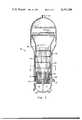
FIG. 1 is an elevational view of a steam generator incorporating the invention;
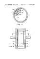
FIG. 2 is a view taken online 2--2 of FIG. 1, showing a tube support;
FIG. 3 is a partial elevational cross-section of one of the tubes of the generator at the location of the tube support, showing the insulating sleeve of the invention;
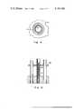
FIG. 4 is a view taken online 4--4 of FIG. 3; and
FIG. 5 is an elevational view of the invention applied to a flow distribution baffle.
Looking now to FIG. 1 of the drawing,numeral 10 denotes a nuclear steam generator in which heating fluid, being water at high temperature, flows frominlet manifold 12, throughtubes 14, and out of theoutlet manifold 16. All of thetubes 14 are secured at their bottom ends to atube sheet 18. The inlet fluid, generally being water below saturation temperature, enters theshell 20 through theinlet 22, mixes with the recirculatory fluid while flowing downwardly through the annular space between theshell 20 andshroud 28, thence upwardly through thetube bundle 14, absorbing heat in doing so, forming a mixture of steam and water. Theseparators 24 at the top of the vessel separate the water from the steam. The steam leaves the unit throughoutlet 26, and the water flows down the annular space for mixing with the water entering theshell 20 throughinlet 22.
Positioned at a number of vertical locations throughout the vessel are a series oftube supports 30. These supports, which are for the purpose of preventing tube vibration induced by the fluid flowing on the shell side of the heat exchanger may be drilledplates 32 as shoen in FIG. 2, havingoversized holes 34 therein, so that they not only keep the tubes in place and prevent vibration, but also permit flow therethrough. If desired,additional flow holes 36 are formed in theplate 32 to permit flow of the heated fluid therethrough. The tube supports could also be in other forms, for example a grid made up of strips or bars of metal, such as shown in U.S. Pat. No. 3,941,188, if desired.
Regardless of the type of tube support used, there exist areas of tight clearance between the tube and support which are hereafter referred to as "crevices". Without the use of this invention, in many instances, the shell side fluid which flows through the crevices is partially or wholly evaporated by the heat transferred from the tube side to the shell side fluid. One consequence of the evaporation process is that the concentration of dissolved solids in the liquid phase may reach the saturation limit so that further evaporation of water will result in precipitation of solids on the tube and plate surfaces. The crevice formed by a tube and its support is especially vulnerable to high solids deposition due to partial or total evaporation of the water as it flows through the crevice. The solids accumulation in the crevice is undesirable, as it can lead to complete blockage of flow through the crevice which increases shell side pressure drop and may induce localized tube corrosion or other phenomena which could reduce the service life of the tube.
In order to prevent the above from occurring, a metal insulating sleeve 40 (FIGS. 3 and 4) is positioned inside of each tube at a location adjacent to the support, to minimize the heat flux or heat transfer to the fluid flowing through the crevice between the tube and support. The outer diameter ofsleeve 40 is somewhat smaller than the inner diameter of thetube 14, so that a layer of stagnant water is trapped in the annular space therebetween. The stagnant water forms an effective insulating barrier, greatly reducing heat transfer. For example, with the sleeve inserted in a typical 3/4" Inconel 600 Pressurized Water Reactor (PWR) steam generator tube, it has been calculated that the localized heat flux in supports near the tube side inlet would be reduced from about 100,000 BTU per hour foot squared to approximately 16,000 BTU per hour foot squared. The geometry of the insulating sleeve is such that most of the static pressure drop due to acceleration of the fluid is recovered.
Theinsulating sleeve 40 can be secured to thetube 14 in any suitable manner. The preferred method would be to expand the lower end of the sleeve into tight engagement with the tube, as shown at 42. This could be done by using pressurized hydraulic or pneumatic fluid inside a flexible bag that can be inserted in the tube through the opened bottom end. If desired, the top end of the insulating sleeve can also be expanded.Drain holes 44 are located near the bottom of theinsulating sleeve 40, to allow the annular space to drain when the unit is not operating.Bleed holes 48 are located at the top to prevent air from becoming trapped behind the sleeves.
In some PWR steam generators, a flow distribution plate 46 (FIGS. 1 and 5) is located above thetube sheet 18. This plate is for the purpose of distributing the flow more equally across the entire cross-section of the shell. When such a distribution plate is used, it may be desirable to minimize the heat flux in the entire space between the tube sheet and the distribution plate, in addition to the crevices between thedistribution plate 46 and thetubes 18. Thus, theinsulating sleeves 50 extend from thetube sheet 18 to a point above thedistribution plate 46 in this arrangement. Thus, this arrangement minimizes boiling in the entire space below thedistribution plate 46, in addition to the area directly adjacent to the distribution plate.
Claims (5)
1. In a shell- and tube- heat exchanger for the generation of vapor by the indirect transfer of heat from a heating fluid to a vaporizable liquid, a pressure vessel, means to introduce vaporizable fluid into the bottom portion of the vessel, an outlet near the top through which vapor is discharged, a bundle of tubes positioned within the vessel, means for circulating heating fluid through the tubes, tube support means positioned within the pressure vessel for preventing tube vibration, the tube support means including horizontally positioned means closely surrounding, but slightly spaced from, each tube in the bundle of tubes at a given elevation, each tube containing an insulating sleeve secured within it, each insulating sleeve being smaller than the inner diameter of the tube it is positioned in, so as to form an annular space therebetween, each insulating sleeve being substantially closed at its upstream end regarding flow of heating fluid, so that the annular space is full of stagnant water forming an insulating barrier during operation, each insulating sleeve being at the same elevation as the tube support means.
2. The shell- and tube- heat exchanger of claim 1, wherein each insulating sleeve has drain holes therein near its bottom end.
3. The shell- and tube- heat exchanger of claim 1 wherein there are a plurality of tube support means, located at a plurality of elevations within the vessel, and there are a plurality of insulating sleeves in each tube, there being one located within each tube at each elevation of the tube support means.
4. The shell- and tube- heat exchanger of claim 1, wherein the tube support means is a plate, having a set of holes therein through which the tubes extend, the holes being slightly larger than the outside diameter of the tube.
5. The shell- and tube- heat exchanger of claim 4 wherein there are a second set of holes in the plate through which the vaporizable fluid can flow.
Priority Applications (4)
| Application Number | Priority Date | Filing Date | Title |
|---|---|---|---|
| US06/017,649US4191246A (en) | 1979-03-05 | 1979-03-05 | Device to reduce local heat flux through a heat exchanger tube |
| EP80101000AEP0015510B1 (en) | 1979-03-05 | 1980-02-28 | Device to reduce local heat flux through a heat exchanger tube |
| DE8080101000TDE3060607D1 (en) | 1979-03-05 | 1980-02-28 | Device to reduce local heat flux through a heat exchanger tube |
| ES489175AES8101264A1 (en) | 1979-03-05 | 1980-03-04 | Device to reduce local heat flux through a heat exchanger tube. |
Applications Claiming Priority (1)
| Application Number | Priority Date | Filing Date | Title |
|---|---|---|---|
| US06/017,649US4191246A (en) | 1979-03-05 | 1979-03-05 | Device to reduce local heat flux through a heat exchanger tube |
Publications (1)
| Publication Number | Publication Date |
|---|---|
| US4191246Atrue US4191246A (en) | 1980-03-04 |
Family
ID=21783786
Family Applications (1)
| Application Number | Title | Priority Date | Filing Date |
|---|---|---|---|
| US06/017,649Expired - LifetimeUS4191246A (en) | 1979-03-05 | 1979-03-05 | Device to reduce local heat flux through a heat exchanger tube |
Country Status (4)
| Country | Link |
|---|---|
| US (1) | US4191246A (en) |
| EP (1) | EP0015510B1 (en) |
| DE (1) | DE3060607D1 (en) |
| ES (1) | ES8101264A1 (en) |
Cited By (34)
| Publication number | Priority date | Publication date | Assignee | Title |
|---|---|---|---|---|
| FR2496843A1 (en)* | 1980-12-23 | 1982-06-25 | Borsig Gmbh | DEVICE FOR THE PRODUCTION OF STEAM IN AMMONIA SYNTHESIS PLANTS |
| US4423703A (en) | 1981-03-09 | 1984-01-03 | Electric Power Research Institute, Inc. | Steam generator or like apparatus including self-cleaning heating element support arrangement |
| US4436146A (en) | 1981-05-20 | 1984-03-13 | Union Carbide Corporation | Shell and tube heat exchanger |
| US4487742A (en)* | 1981-05-22 | 1984-12-11 | Commissariat A L'energie Atomique | Fast neutron nuclear reactor with internal capillary structure piping |
| FR2565322A1 (en)* | 1984-05-29 | 1985-12-06 | Commissariat Energie Atomique | DEVICE FOR INJECTING A LIQUID IN A TUBE AND STEAM GENERATOR COMPRISING SAID DEVICE |
| US4576228A (en)* | 1984-02-03 | 1986-03-18 | The United States Of America As Represented By The United States Department Of Energy | Minimum wear tube support hole design |
| US4590991A (en)* | 1984-01-09 | 1986-05-27 | Westinghouse Electric Corp. | Flexible stabilizer for degraded heat exchanger tubing |
| USH119H (en) | 1983-07-15 | 1986-09-02 | The United States Of America As Represented By The United States Department Of Energy | Passive emergency core cooling system for a liquid metal fast |
| US4652020A (en)* | 1984-03-22 | 1987-03-24 | National Nuclear Corporation Limited | Pipework |
| EP0149074B1 (en)* | 1983-12-21 | 1988-02-10 | Westinghouse Electric Corporation | Corrosion resistant steam generator |
| US4735263A (en)* | 1985-12-23 | 1988-04-05 | Stein Industrie | Flow control device for heat exchanger tube |
| US4742691A (en)* | 1986-06-02 | 1988-05-10 | White Consolidated Industries, Inc. | Dehumidifier |
| US20040146134A1 (en)* | 2002-10-31 | 2004-07-29 | Klarner Richard G. | Heat exchanger tube support structure |
| US6810101B2 (en)* | 1999-11-01 | 2004-10-26 | Babcock & Wilcox Canada, Ltd. | Heat exchanger tube support structure |
| US6960333B2 (en) | 1999-06-30 | 2005-11-01 | Rohm And Haas Company | High performance heat exchangers |
| US20100199977A1 (en)* | 2009-02-12 | 2010-08-12 | Babcock Power Services, Inc. | Panel support system for solar boilers |
| US20100199976A1 (en)* | 2009-02-12 | 2010-08-12 | Babcock Power Services Inc. | Spray stations for temperature control in solar boilers |
| US20100199979A1 (en)* | 2009-02-12 | 2010-08-12 | Babcock Power Services Inc. | Corner structure for walls of panels in solar boilers |
| US20100199974A1 (en)* | 2009-02-12 | 2010-08-12 | Babcock Power Services Inc. | Solar receiver panels |
| US20110079217A1 (en)* | 2009-02-12 | 2011-04-07 | Babcock Power Services, Inc. | Piping, header, and tubing arrangements for solar boilers |
| US20110209697A1 (en)* | 2009-02-12 | 2011-09-01 | Babcock Power Services, Inc. | Modular solar receiver panels and solar boilers with modular receiver panels |
| US20120167839A1 (en)* | 2010-12-29 | 2012-07-05 | Westinghouse Electric Company Llc | Anti-vibration tube support plate arrangement for steam generators |
| US8316843B2 (en) | 2009-02-12 | 2012-11-27 | Babcock Power Services Inc. | Arrangement of tubing in solar boiler panels |
| US20130121453A1 (en)* | 2011-11-10 | 2013-05-16 | Scott J. Shargots | Pressurized water reactor with upper plenum including cross-flow blocking weir |
| US8573196B2 (en) | 2010-08-05 | 2013-11-05 | Babcock Power Services, Inc. | Startup/shutdown systems and methods for a solar thermal power generating facility |
| US20140116360A1 (en)* | 2012-10-31 | 2014-05-01 | Westinghouse Electric Company Llc | Method and apparatus for securing tubes in a steam generator against vibration |
| US20140165650A1 (en)* | 2012-12-13 | 2014-06-19 | Richard John Jibb | Heat exchanger and distillation column arrangement |
| US8893714B2 (en) | 2009-02-12 | 2014-11-25 | Babcock Power Services, Inc. | Expansion joints for panels in solar boilers |
| US20140352931A1 (en)* | 2013-05-31 | 2014-12-04 | Steve Turner | Corrosion Resistant Air Preheater with Lined Tubes |
| US9038624B2 (en) | 2011-06-08 | 2015-05-26 | Babcock Power Services, Inc. | Solar boiler tube panel supports |
| US20150159956A1 (en)* | 2013-12-09 | 2015-06-11 | Balcke-Dürr GmbH | Tube Bundle Heat Exchanger Having Straight-Tube Configuration, Process Gas Cooler, Cooler For Gas Turbine Cooling Air, Gas Turbine Or Gas And Steam Turbine Power Plant, And Method For The Cooling Of Cooling Air |
| US9134043B2 (en) | 2009-02-12 | 2015-09-15 | Babcock Power Services Inc. | Heat transfer passes for solar boilers |
| CN109631621A (en)* | 2019-01-10 | 2019-04-16 | 上海盛韬半导体科技有限公司 | A kind of heat exchanger and preparation method thereof suitable for the purification of high prefect dielectric |
| CN114577040A (en)* | 2022-03-28 | 2022-06-03 | 浙江尔格科技股份有限公司 | Cooling device |
Citations (8)
| Publication number | Priority date | Publication date | Assignee | Title |
|---|---|---|---|---|
| US1802766A (en)* | 1927-12-08 | 1931-04-28 | Babcock & Wilcox Co | Pipe or tube joint |
| CA509187A (en)* | 1955-01-18 | Schultz Herman | Self sealing tube inserts | |
| US3503440A (en)* | 1968-12-23 | 1970-03-31 | Combustion Eng | Formed plate tube support |
| US3610329A (en)* | 1968-12-27 | 1971-10-05 | Basf Ag | Tube plate for hot gas coolers |
| US3726339A (en)* | 1969-10-13 | 1973-04-10 | North American Rockwell | Steam generator protector |
| US3916990A (en)* | 1974-02-25 | 1975-11-04 | Foster Wheeler Corp | Gas turbine regenerator |
| GB1507833A (en)* | 1975-12-01 | 1978-04-19 | Atomic Energy Authority Uk | Tube in shell heat exchangers |
| US4114684A (en)* | 1977-04-11 | 1978-09-19 | General Electric Company | Tube support system for heat exchanger |
Family Cites Families (3)
| Publication number | Priority date | Publication date | Assignee | Title |
|---|---|---|---|---|
| BE566748A (en)* | ||||
| DE930148C (en)* | 1943-08-04 | 1955-07-11 | Vaillant Joh Kg | Device to prevent corrosion, especially on the cooling pipes of heat exchangers |
| US4120350A (en)* | 1975-03-19 | 1978-10-17 | The Babcock & Wilcox Company | Tube support structure |
- 1979
- 1979-03-05USUS06/017,649patent/US4191246A/ennot_activeExpired - Lifetime
- 1980
- 1980-02-28DEDE8080101000Tpatent/DE3060607D1/ennot_activeExpired
- 1980-02-28EPEP80101000Apatent/EP0015510B1/ennot_activeExpired
- 1980-03-04ESES489175Apatent/ES8101264A1/ennot_activeExpired
Patent Citations (8)
| Publication number | Priority date | Publication date | Assignee | Title |
|---|---|---|---|---|
| CA509187A (en)* | 1955-01-18 | Schultz Herman | Self sealing tube inserts | |
| US1802766A (en)* | 1927-12-08 | 1931-04-28 | Babcock & Wilcox Co | Pipe or tube joint |
| US3503440A (en)* | 1968-12-23 | 1970-03-31 | Combustion Eng | Formed plate tube support |
| US3610329A (en)* | 1968-12-27 | 1971-10-05 | Basf Ag | Tube plate for hot gas coolers |
| US3726339A (en)* | 1969-10-13 | 1973-04-10 | North American Rockwell | Steam generator protector |
| US3916990A (en)* | 1974-02-25 | 1975-11-04 | Foster Wheeler Corp | Gas turbine regenerator |
| GB1507833A (en)* | 1975-12-01 | 1978-04-19 | Atomic Energy Authority Uk | Tube in shell heat exchangers |
| US4114684A (en)* | 1977-04-11 | 1978-09-19 | General Electric Company | Tube support system for heat exchanger |
Cited By (52)
| Publication number | Priority date | Publication date | Assignee | Title |
|---|---|---|---|---|
| NL8104758A (en)* | 1980-12-23 | 1982-07-16 | Borsig Gmbh | DEVICE FOR OBTAINING VAPOR FROM EQUIPMENT FOR THE SYNTHESIS OF AMMONIAK. |
| FR2496843A1 (en)* | 1980-12-23 | 1982-06-25 | Borsig Gmbh | DEVICE FOR THE PRODUCTION OF STEAM IN AMMONIA SYNTHESIS PLANTS |
| US4423703A (en) | 1981-03-09 | 1984-01-03 | Electric Power Research Institute, Inc. | Steam generator or like apparatus including self-cleaning heating element support arrangement |
| US4436146A (en) | 1981-05-20 | 1984-03-13 | Union Carbide Corporation | Shell and tube heat exchanger |
| US4487742A (en)* | 1981-05-22 | 1984-12-11 | Commissariat A L'energie Atomique | Fast neutron nuclear reactor with internal capillary structure piping |
| USH119H (en) | 1983-07-15 | 1986-09-02 | The United States Of America As Represented By The United States Department Of Energy | Passive emergency core cooling system for a liquid metal fast |
| EP0149074B1 (en)* | 1983-12-21 | 1988-02-10 | Westinghouse Electric Corporation | Corrosion resistant steam generator |
| US4590991A (en)* | 1984-01-09 | 1986-05-27 | Westinghouse Electric Corp. | Flexible stabilizer for degraded heat exchanger tubing |
| US4576228A (en)* | 1984-02-03 | 1986-03-18 | The United States Of America As Represented By The United States Department Of Energy | Minimum wear tube support hole design |
| US4652020A (en)* | 1984-03-22 | 1987-03-24 | National Nuclear Corporation Limited | Pipework |
| EP0165846A1 (en)* | 1984-05-29 | 1985-12-27 | Commissariat A L'energie Atomique | Liquid injection device in a tube and steam generator having such a device |
| US4721067A (en)* | 1984-05-29 | 1988-01-26 | Commissariat A L'energie Atomique | Device for injecting a liquid into a tube and steam generator comprising this device |
| FR2565322A1 (en)* | 1984-05-29 | 1985-12-06 | Commissariat Energie Atomique | DEVICE FOR INJECTING A LIQUID IN A TUBE AND STEAM GENERATOR COMPRISING SAID DEVICE |
| US4735263A (en)* | 1985-12-23 | 1988-04-05 | Stein Industrie | Flow control device for heat exchanger tube |
| US4742691A (en)* | 1986-06-02 | 1988-05-10 | White Consolidated Industries, Inc. | Dehumidifier |
| US6960333B2 (en) | 1999-06-30 | 2005-11-01 | Rohm And Haas Company | High performance heat exchangers |
| US6810101B2 (en)* | 1999-11-01 | 2004-10-26 | Babcock & Wilcox Canada, Ltd. | Heat exchanger tube support structure |
| US20040146134A1 (en)* | 2002-10-31 | 2004-07-29 | Klarner Richard G. | Heat exchanger tube support structure |
| US6914955B2 (en)* | 2002-10-31 | 2005-07-05 | Babcock & Wilcox Canada Ltd. | Heat exchanger tube support structure |
| US8356591B2 (en) | 2009-02-12 | 2013-01-22 | Babcock Power Services, Inc. | Corner structure for walls of panels in solar boilers |
| US8397710B2 (en) | 2009-02-12 | 2013-03-19 | Babcock Power Services Inc. | Solar receiver panels |
| US20100199979A1 (en)* | 2009-02-12 | 2010-08-12 | Babcock Power Services Inc. | Corner structure for walls of panels in solar boilers |
| US20100199974A1 (en)* | 2009-02-12 | 2010-08-12 | Babcock Power Services Inc. | Solar receiver panels |
| US20110079217A1 (en)* | 2009-02-12 | 2011-04-07 | Babcock Power Services, Inc. | Piping, header, and tubing arrangements for solar boilers |
| US20110209697A1 (en)* | 2009-02-12 | 2011-09-01 | Babcock Power Services, Inc. | Modular solar receiver panels and solar boilers with modular receiver panels |
| US9134043B2 (en) | 2009-02-12 | 2015-09-15 | Babcock Power Services Inc. | Heat transfer passes for solar boilers |
| US8316843B2 (en) | 2009-02-12 | 2012-11-27 | Babcock Power Services Inc. | Arrangement of tubing in solar boiler panels |
| US20100199977A1 (en)* | 2009-02-12 | 2010-08-12 | Babcock Power Services, Inc. | Panel support system for solar boilers |
| US8893714B2 (en) | 2009-02-12 | 2014-11-25 | Babcock Power Services, Inc. | Expansion joints for panels in solar boilers |
| US8430092B2 (en) | 2009-02-12 | 2013-04-30 | Babcock Power Services, Inc. | Panel support system for solar boilers |
| US9163857B2 (en) | 2009-02-12 | 2015-10-20 | Babcock Power Services, Inc. | Spray stations for temperature control in solar boilers |
| US20100199976A1 (en)* | 2009-02-12 | 2010-08-12 | Babcock Power Services Inc. | Spray stations for temperature control in solar boilers |
| US8517008B2 (en) | 2009-02-12 | 2013-08-27 | Babcock Power Services, Inc. | Modular solar receiver panels and solar boilers with modular receiver panels |
| US8733340B2 (en) | 2009-02-12 | 2014-05-27 | Babcock Power Services, Inc. | Arrangement of tubing in solar boiler panels |
| US9347685B2 (en) | 2010-08-05 | 2016-05-24 | Babcock Power Services Inc. | Startup systems and methods for solar boilers |
| US8573196B2 (en) | 2010-08-05 | 2013-11-05 | Babcock Power Services, Inc. | Startup/shutdown systems and methods for a solar thermal power generating facility |
| US9697919B2 (en)* | 2010-12-29 | 2017-07-04 | Westinghouse Electric Company, Llc | Anti-vibration tube support plate arrangement for steam generators |
| US20120167839A1 (en)* | 2010-12-29 | 2012-07-05 | Westinghouse Electric Company Llc | Anti-vibration tube support plate arrangement for steam generators |
| US9038624B2 (en) | 2011-06-08 | 2015-05-26 | Babcock Power Services, Inc. | Solar boiler tube panel supports |
| US9558855B2 (en)* | 2011-11-10 | 2017-01-31 | Bwxt Nuclear Energy, Inc. | Pressurized water reactor with upper plenum including cross-flow blocking weir |
| WO2013095741A3 (en)* | 2011-11-10 | 2013-08-15 | Babcock & Wilcox Nuclear Energy, Inc. | Pressurized water reactor with upper plenum including cross-flow blocking weir |
| US20130121453A1 (en)* | 2011-11-10 | 2013-05-16 | Scott J. Shargots | Pressurized water reactor with upper plenum including cross-flow blocking weir |
| US20140116360A1 (en)* | 2012-10-31 | 2014-05-01 | Westinghouse Electric Company Llc | Method and apparatus for securing tubes in a steam generator against vibration |
| US20140165650A1 (en)* | 2012-12-13 | 2014-06-19 | Richard John Jibb | Heat exchanger and distillation column arrangement |
| US20140352931A1 (en)* | 2013-05-31 | 2014-12-04 | Steve Turner | Corrosion Resistant Air Preheater with Lined Tubes |
| US11149945B2 (en)* | 2013-05-31 | 2021-10-19 | Corrosion Monitoring Service, Inc. | Corrosion resistant air preheater with lined tubes |
| US20150159956A1 (en)* | 2013-12-09 | 2015-06-11 | Balcke-Dürr GmbH | Tube Bundle Heat Exchanger Having Straight-Tube Configuration, Process Gas Cooler, Cooler For Gas Turbine Cooling Air, Gas Turbine Or Gas And Steam Turbine Power Plant, And Method For The Cooling Of Cooling Air |
| US10006719B2 (en)* | 2013-12-09 | 2018-06-26 | Balcke-Durr Gmbh | Tube bundle heat exchanger having straight-tube configuration, process gas cooler, cooler for gas turbine cooling air, gas turbine or gas and steam turbine power plant, and method for the cooling of cooling air |
| CN109631621A (en)* | 2019-01-10 | 2019-04-16 | 上海盛韬半导体科技有限公司 | A kind of heat exchanger and preparation method thereof suitable for the purification of high prefect dielectric |
| CN109631621B (en)* | 2019-01-10 | 2023-11-10 | 上海盛韬半导体科技有限公司 | Heat exchanger suitable for purifying high-purity medium and preparation method thereof |
| CN114577040A (en)* | 2022-03-28 | 2022-06-03 | 浙江尔格科技股份有限公司 | Cooling device |
| CN114577040B (en)* | 2022-03-28 | 2023-09-22 | 浙江尔格科技股份有限公司 | Cooling device |
Also Published As
| Publication number | Publication date |
|---|---|
| ES489175A0 (en) | 1980-12-01 |
| EP0015510A1 (en) | 1980-09-17 |
| ES8101264A1 (en) | 1980-12-01 |
| DE3060607D1 (en) | 1982-08-19 |
| EP0015510B1 (en) | 1982-06-30 |
Similar Documents
| Publication | Publication Date | Title |
|---|---|---|
| US4191246A (en) | Device to reduce local heat flux through a heat exchanger tube | |
| RU2125744C1 (en) | System for passive heat dissipation from inner space of nuclear reactor containment | |
| US2946732A (en) | Nuclear power plant | |
| US3213833A (en) | Unitized vapor generation system | |
| CA2081498A1 (en) | Passive three-phase heat tube for the protection of apparatus from exceeding maximum or minimum safe working temperatures | |
| US3437077A (en) | Once-through vapor generator | |
| KR102190135B1 (en) | Steam generator with a horizontal bundle of heat exchange tubes and method for assembling same | |
| US4487742A (en) | Fast neutron nuclear reactor with internal capillary structure piping | |
| US3854528A (en) | Heat-exchanger module | |
| US3305002A (en) | Fluid pressurizer | |
| DE1927949A1 (en) | Steam generation and overheating device, especially for with molten metal, molten metal salt or the like. nuclear reactors working as heat exchangers | |
| JP3139856B2 (en) | Tube heat exchanger | |
| US3112735A (en) | Liquid metal heated vapor generator | |
| DE2249581A1 (en) | HEAT EXCHANGER | |
| US3279439A (en) | Vapor generating superheating and reheating unit | |
| US5114667A (en) | High temperature reactor having an improved fluid coolant circulation system | |
| FR2106620B1 (en) | ||
| US4453501A (en) | Transducer for determining if steam generator tubes are locked in at support plate | |
| JPS6158721B2 (en) | ||
| US5323736A (en) | Steam generator with device for the distribution of feed water and recirculation water in the secondary part | |
| US3354869A (en) | Heat exchangers | |
| US3739752A (en) | Boiler drum structure for rapid temperature changes | |
| DE2536757A1 (en) | Shell and tube steam generator - for sodium-cooled reactor with gas-insulated feedwater tubes | |
| US3428119A (en) | Heat exchanger | |
| RU2169881C2 (en) | Stram generator |