US4189987A - Vehicle cab temperature control system - Google Patents
Vehicle cab temperature control systemDownload PDFInfo
- Publication number
- US4189987A US4189987AUS05/921,384US92138478AUS4189987AUS 4189987 AUS4189987 AUS 4189987AUS 92138478 AUS92138478 AUS 92138478AUS 4189987 AUS4189987 AUS 4189987A
- Authority
- US
- United States
- Prior art keywords
- aperture
- duct
- air
- temperature control
- service
- Prior art date
- Legal status (The legal status is an assumption and is not a legal conclusion. Google has not performed a legal analysis and makes no representation as to the accuracy of the status listed.)
- Expired - Lifetime
Links
Images

Classifications
- B—PERFORMING OPERATIONS; TRANSPORTING
- B60—VEHICLES IN GENERAL
- B60H—ARRANGEMENTS OF HEATING, COOLING, VENTILATING OR OTHER AIR-TREATING DEVICES SPECIALLY ADAPTED FOR PASSENGER OR GOODS SPACES OF VEHICLES
- B60H1/00—Heating, cooling or ventilating [HVAC] devices
- B60H1/00357—Air-conditioning arrangements specially adapted for particular vehicles
- B60H1/00378—Air-conditioning arrangements specially adapted for particular vehicles for tractor or load vehicle cabins
- B—PERFORMING OPERATIONS; TRANSPORTING
- B60—VEHICLES IN GENERAL
- B60H—ARRANGEMENTS OF HEATING, COOLING, VENTILATING OR OTHER AIR-TREATING DEVICES SPECIALLY ADAPTED FOR PASSENGER OR GOODS SPACES OF VEHICLES
- B60H1/00—Heating, cooling or ventilating [HVAC] devices
- B60H1/00007—Combined heating, ventilating, or cooling devices
- B60H1/00207—Combined heating, ventilating, or cooling devices characterised by the position of the HVAC devices with respect to the passenger compartment
- B60H2001/00235—Devices in the roof area of the passenger compartment
Definitions
- This inventionrelates generally to a vehicle cab ventilating system and more particularly concerns cab ventilating systems which control the temperature of the air entering the operator enclosure.
- the systems described in these patentssuffer from the weaknesses that have plagued the conventional systems since they were first introduced.
- the first weaknesslies in the fact that the conventional systems do not have sufficient insulation of the temperature control system from the extreme temperature variances to provide an efficient temperature control system.
- the second weaknessis twofold, and arises from the fact that the air flow from the filter to the operator enclosure is sealed at the interface of large pieces formed from sheet metal. This sealing process is both ineffective and extremely costly to produce, because the massive size of the passage produces an incredibly long interface that must be sealed, while the violent nature and extreme temperature range of the working environment of the vehicle unduly shortens the effective life of the seal.
- This improvement of a vehicle cab temperature control system for a cab having an operator enclosure with a roof and an outwardly exposed air filter attached to the roofincludes a blower and a temperature control unit mounted within a duct which is secured to both the roof and to the air filter.
- the ductis spaced apart from the roof, thereby forming a chamber which receives controlled air from the temperature control unit.
- the flow of controlled airis produced by the blower as it moves the air through the air filter into the duct through its inlet aperture and then through the temperature control unit within the duct.
- the controlled airthen exits the duct through either the duct's bleed aperture into the chamber or through the duct's outlet aperture into the operator enclosure.
- FIG. 1is a right side view of a cab incorporating the invention
- FIG. 2is a top view of the cab of FIG. 1;
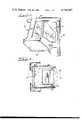
- FIG. 3is an enlarged sectional view along line 3--3 of FIG. 2.
- FIG. 1there is shown a cab which incorporates the temperature control system of the present invention.
- the cabprovides an operator environment 12 by sealibly connecting the walls 14, the floor 16 and the roof 18.
- FIG. 3shows the temperature control system 20, secured to the operator enclosure by nuts and bolts at 22 and by bonding at 24.
- FIG. 3also depicts the cab's air filter 26 conventionally secured to the roof 18 of the cab (the securing mechanism for the air filter is not shown).
- the basic elements of the air temperature control system of the preferred embodimentare a duct 28, a blower 30 and an air temperature control unit 32.
- the duct of the illustrated embodimentincludes a top panel 34 which is substantially C-shaped to provide the top and side surfaces of the rear portion of the duct 28, a headliner 36 which provides a substantial portion of the lower section of the duct 28 and an extension panel 38 which provides the entire front section of the duct.
- the top panel 34 and the headliner 36are molded fiberglass pieces 35 and sheet metal pieces 37 which are bonded together along their interface 40.
- the headlineris constructed by bonding a main element 42 with a rear panel 44 along their interface 46.
- the extension panel 38is formed by using a plurality of nuts and bolts 48 and calking 49 to rigidly connect and seal a plurality of sheet metal members 50 and plastic member 51.
- the interface between the extension panel 38, the top panel 34 and headliner 36is sealed by a grooved foam connector 52 which fits over the exposed surface of the panels and headliner.
- the headliner 36is secured and sealed by nuts and bolts 48 and calking 49 to the extension panel 38 along their interface 54.
- the preferred embodimenthas the blower 30 and the air temperature control unit 32 mounted within the extension panel 38 of the duct 28.
- the present air temperature control unitconsists of an evaporator coil 56 utilized to reduce the temperature of the air within the operator enclosure 12, and a heater coil 58 utilized to increase the temperature within the operator enclosure 12.
- the extension panel 38is provided with a condensate removal system 60.
- the headliner 36includes an inlet aperture 62
- the extension panel 38includes an outlet aperture 64, bleeder aperture 66 and bleeder passage 68.
- the bleeder aperture 66 and bleeder passage 68provide the connection between the controlled air within the extension panel 38 and the air within the chamber 70.
- the chamber 70is produced by the separation between the duct 28 and the roof 18.
- FIG. 3the passage 68 is shown in a tubular member 72 which is secured and sealed by nuts and bolts 48 and calking 49 to a sheet metal member 50 of extension panel 38.
- the tubular member 72has an entrance aperture 74 whereby controlled air enters the tube. The controlled air is communicated to the chamber 70 when it exits the tube 72 and extension panel 38 through exit aperture 76, as shown in FIG. 2.
- the blower 30draws air from outside the operator enclosure 12 through the air filter 26, the inlet aperture 62, between the headliner 36 and the top panel 34 and into the air temperature control unit 32.
- the airis then treated by either the evaporator coil 56 or the heater coil 58.
- the controlled airthen passes through the blower 30, and exits into either the chamber 70 via the bleed aperture 66 and bleed passage 68 or into the operator enclosure 12 via the outlet aperture 64. Since the bleed aperture 66 and bleed passage 68 present a greater resistence to air flow than does the outlet aperture 68 due to the larger opening of the outlet aperture 64, the great majority of the controlled air will enter the operator enclosure 12.
- the headliner of the preferred embodimentis provided with a foam barrier 78, thereby reducing the heat transmission between the duct 28 and the operator enclosure 12.
- the preferred embodimenthas a defrosting aperture 79 in the extension panel 38 to provide a constant flow of controlled air over the cab windshield 81.
- the preferred embodimentalso provides access to the air temperature control unit 32 and the blower 30.
- This accessis produced by a service aperture 80 and the cover plate 82 of the roof 18 and an access aperture 84 in the extension panel 38.
- the integrity of the chamber 70is maintained by sealing the cover plate 82 with a service plate 86 and a gasket 89, with the service plate 86 being secured to the cover plate 88 by nuts and bolts 90.
- This sealing arrangementeliminates the leakage of air into the chamber 70 through the service aperture 80, while a foam member 92 is compressed between the extension panel 38 and the cover plate 82 to prevent leakage of uncontrolled air from the duct 28 through the access aperture 84 into the chamber 70.
- the present inventionprovides a vehicle cab air temperature control system which increases the efficiency of the system by utilizing a pressurized chamber of controlled air to insulate the system from the temperatures existing outside the system, while increasing the effectiveness and decreasing the cost of protecting the system against leaks of external dirt and uncontrolled air into the system by maximizing the bonded interfaces of the system elements thereby minimizing the conventionally sealed interfaces of the element.
Landscapes
- Physics & Mathematics (AREA)
- Thermal Sciences (AREA)
- Engineering & Computer Science (AREA)
- Mechanical Engineering (AREA)
- Body Structure For Vehicles (AREA)
- Component Parts Of Construction Machinery (AREA)
Abstract
Description
Claims (6)
Priority Applications (1)
| Application Number | Priority Date | Filing Date | Title |
|---|---|---|---|
| US05/921,384US4189987A (en) | 1978-07-03 | 1978-07-03 | Vehicle cab temperature control system |
Applications Claiming Priority (1)
| Application Number | Priority Date | Filing Date | Title |
|---|---|---|---|
| US05/921,384US4189987A (en) | 1978-07-03 | 1978-07-03 | Vehicle cab temperature control system |
Publications (1)
| Publication Number | Publication Date |
|---|---|
| US4189987Atrue US4189987A (en) | 1980-02-26 |
Family
ID=25445347
Family Applications (1)
| Application Number | Title | Priority Date | Filing Date |
|---|---|---|---|
| US05/921,384Expired - LifetimeUS4189987A (en) | 1978-07-03 | 1978-07-03 | Vehicle cab temperature control system |
Country Status (1)
| Country | Link |
|---|---|
| US (1) | US4189987A (en) |
Cited By (42)
| Publication number | Priority date | Publication date | Assignee | Title |
|---|---|---|---|---|
| USD266923S (en) | 1980-02-06 | 1982-11-16 | Parks Edgar L | Ventilating hatch |
| FR2524411A1 (en)* | 1982-04-05 | 1983-10-07 | Caterpillar Tractor Co | IMPROVEMENTS IN WALLS FOR VEHICLE CABS |
| US4503749A (en)* | 1984-03-28 | 1985-03-12 | Allis-Chalmers Corporation | Combine visor with environmental components |
| US4709623A (en)* | 1986-08-22 | 1987-12-01 | Nordyne, Inc. | Ceiling distributor duct assembly for rooftop air conditioners |
| US4722747A (en)* | 1986-06-16 | 1988-02-02 | Armbruster Joseph M | Add-on vehicle air filtration system |
| US4763564A (en)* | 1987-04-17 | 1988-08-16 | Ford Motor Company | Multiple unit automotive climate control system |
| DE4115176A1 (en)* | 1991-05-09 | 1992-11-12 | Daimler Benz Ag | DEVICE FOR VENTILATING, HEATING AND / OR COOLING LARGE VEHICLE SPACES |
| US5501634A (en)* | 1994-10-31 | 1996-03-26 | Wilder; Timothy S. | Air conditioner cover assembly |
| EP0733503A1 (en)* | 1995-03-18 | 1996-09-25 | New Holland U.K. Limited | Roof for a vehicle cab |
| US5695238A (en)* | 1995-06-20 | 1997-12-09 | Caterpillar Inc. | Non-Metalic roof for a work machine |
| DE19624669A1 (en)* | 1996-06-20 | 1998-01-02 | Schultz Gmbh Aurora | Roof heater, e.g. for vehicle cabin |
| US5921619A (en)* | 1997-07-17 | 1999-07-13 | Case Corporation | Air handling system for vehicle cab |
| US6086145A (en)* | 1998-07-16 | 2000-07-11 | Textron Automotive Company Inc. | Blow molded headliner |
| US6126539A (en)* | 1998-10-01 | 2000-10-03 | Caterpillar S.A.R.L. | Pilot valve mounting which functions as a hot air duct |
| US6279978B1 (en)* | 1999-10-05 | 2001-08-28 | Deere & Company | Work vehicle roof structure |
| US6322136B2 (en) | 1999-10-05 | 2001-11-27 | Deere & Company | Vehicle headliner mounting structure |
| US6361428B1 (en) | 2000-07-06 | 2002-03-26 | International Truck And Engine Corp. | Vehicle ventilation system |
| US6780097B2 (en) | 2003-01-29 | 2004-08-24 | Deere & Company | Two piece vehicle roof structure having an integrated HVAC system |
| US6782708B1 (en)* | 2003-07-28 | 2004-08-31 | James R. Boer | Air conditioner coil access door kit and method of installation |
| US20050005532A1 (en)* | 2003-06-12 | 2005-01-13 | Kubota Corporation | Work-vehicle cabin having air-conditioning unit |
| DE102004054169B3 (en)* | 2004-09-20 | 2006-04-13 | Konvekta Ag | Air conditioning unit especially for mounting on roof of passenger carrying vehicle has first surface section of underside of preformed component conforming to external contour of ventilation fan |
| US20080014856A1 (en)* | 2006-07-12 | 2008-01-17 | Cnh America Llc | Filter purge control for hvac variable air circulation system |
| US20080032619A1 (en)* | 2006-07-12 | 2008-02-07 | Cnh America Llc | Filter purge control for hvac fixed air circulation system |
| US20080119129A1 (en)* | 2006-11-22 | 2008-05-22 | Dometic Corporation | Air distribution apparatus |
| US20100120345A1 (en)* | 2008-11-07 | 2010-05-13 | Aidan Ryan | Fresh air box |
| US20170129306A1 (en)* | 2014-07-30 | 2017-05-11 | Yanmar Co. Ltd. | Work vehicle |
| CN106915218A (en)* | 2017-03-23 | 2017-07-04 | 烟台镇泰滚塑有限公司 | A kind of independent double air channel rotational moulding ceilings of built-in air-conditioning |
| USD811566S1 (en) | 2016-02-12 | 2018-02-27 | Dometic Sweden Ab | Recreational vehicle air-conditioning unit |
| USD817466S1 (en) | 2016-01-19 | 2018-05-08 | Dometic Sweden Ab | Air shroud assembly |
| US9975405B2 (en) | 2013-03-14 | 2018-05-22 | Dometic Corporation | Modular air grill assembly |
| US20180178617A1 (en)* | 2016-12-27 | 2018-06-28 | Cnh Industrial America Llc | Airflow control system of a work vehicle |
| USD824499S1 (en) | 2016-04-28 | 2018-07-31 | Dometic Sweden Ab | Air-conditioning unit |
| USD850609S1 (en) | 2015-10-15 | 2019-06-04 | Dometic Sweden Ab | Modular air grill |
| US10589593B2 (en) | 2016-01-19 | 2020-03-17 | Dometic Sweden Ab | Parking cooler |
| US10675941B2 (en) | 2016-02-22 | 2020-06-09 | Dometic Sweden Ab | Air-conditioner control |
| USD905217S1 (en) | 2018-09-05 | 2020-12-15 | Dometic Sweden Ab | Air conditioning apparatus |
| USD907183S1 (en) | 2016-11-23 | 2021-01-05 | Dometic Sweden Ab | Air conditioning apparatus |
| USD915569S1 (en) | 2017-02-17 | 2021-04-06 | Dometic Sweden Ab | Shroud assembly |
| US11034208B2 (en) | 2016-02-22 | 2021-06-15 | Dometic Sweden Ab | Vehicle air conditioner |
| US11590824B2 (en) | 2018-04-20 | 2023-02-28 | Deere & Company | Roof structure and cab |
| US11772452B2 (en) | 2017-11-16 | 2023-10-03 | Dometic Sweden Ab | Air conditioning apparatus for recreational vehicles |
| US12043081B2 (en) | 2019-10-17 | 2024-07-23 | Dometic Sweden Ab | Air conditioning apparatus for recreational vehicles |
Citations (8)
| Publication number | Priority date | Publication date | Assignee | Title |
|---|---|---|---|---|
| US2153147A (en)* | 1936-08-12 | 1939-04-04 | Evans Prod Co | Vehicle ventilating and signal unit |
| US2158332A (en)* | 1936-10-01 | 1939-05-16 | Evans Prod Co | Vehicle ventilating apparatus |
| US2720149A (en)* | 1953-09-21 | 1955-10-11 | Groene Willard Le Blond | Automobile air conditioning duct system |
| US3555846A (en)* | 1968-12-13 | 1971-01-19 | Stolper Ind Inc | Air-conditioned vehicle cab |
| US3626713A (en)* | 1970-04-23 | 1971-12-14 | Case Co J I | Vehicle cab air conditioning system |
| US3868896A (en)* | 1973-03-28 | 1975-03-04 | Massey Ferguson Inc | Vehicle cab enclosure with ventilation means |
| US4120527A (en)* | 1977-04-15 | 1978-10-17 | Caterpillar Tractor Co. | Cab design |
| US4140047A (en)* | 1978-04-07 | 1979-02-20 | Sperry Rand Corporation | Mobile cab with air filter |
- 1978
- 1978-07-03USUS05/921,384patent/US4189987A/ennot_activeExpired - Lifetime
Patent Citations (8)
| Publication number | Priority date | Publication date | Assignee | Title |
|---|---|---|---|---|
| US2153147A (en)* | 1936-08-12 | 1939-04-04 | Evans Prod Co | Vehicle ventilating and signal unit |
| US2158332A (en)* | 1936-10-01 | 1939-05-16 | Evans Prod Co | Vehicle ventilating apparatus |
| US2720149A (en)* | 1953-09-21 | 1955-10-11 | Groene Willard Le Blond | Automobile air conditioning duct system |
| US3555846A (en)* | 1968-12-13 | 1971-01-19 | Stolper Ind Inc | Air-conditioned vehicle cab |
| US3626713A (en)* | 1970-04-23 | 1971-12-14 | Case Co J I | Vehicle cab air conditioning system |
| US3868896A (en)* | 1973-03-28 | 1975-03-04 | Massey Ferguson Inc | Vehicle cab enclosure with ventilation means |
| US4120527A (en)* | 1977-04-15 | 1978-10-17 | Caterpillar Tractor Co. | Cab design |
| US4140047A (en)* | 1978-04-07 | 1979-02-20 | Sperry Rand Corporation | Mobile cab with air filter |
Cited By (63)
| Publication number | Priority date | Publication date | Assignee | Title |
|---|---|---|---|---|
| USD266923S (en) | 1980-02-06 | 1982-11-16 | Parks Edgar L | Ventilating hatch |
| FR2524411A1 (en)* | 1982-04-05 | 1983-10-07 | Caterpillar Tractor Co | IMPROVEMENTS IN WALLS FOR VEHICLE CABS |
| US4503749A (en)* | 1984-03-28 | 1985-03-12 | Allis-Chalmers Corporation | Combine visor with environmental components |
| US4722747A (en)* | 1986-06-16 | 1988-02-02 | Armbruster Joseph M | Add-on vehicle air filtration system |
| US4709623A (en)* | 1986-08-22 | 1987-12-01 | Nordyne, Inc. | Ceiling distributor duct assembly for rooftop air conditioners |
| US4763564A (en)* | 1987-04-17 | 1988-08-16 | Ford Motor Company | Multiple unit automotive climate control system |
| DE4115176A1 (en)* | 1991-05-09 | 1992-11-12 | Daimler Benz Ag | DEVICE FOR VENTILATING, HEATING AND / OR COOLING LARGE VEHICLE SPACES |
| US5501634A (en)* | 1994-10-31 | 1996-03-26 | Wilder; Timothy S. | Air conditioner cover assembly |
| EP0733503A1 (en)* | 1995-03-18 | 1996-09-25 | New Holland U.K. Limited | Roof for a vehicle cab |
| US5690549A (en)* | 1995-03-18 | 1997-11-25 | New Holland North America, Inc. | Roof for a vehicle cab |
| US5695238A (en)* | 1995-06-20 | 1997-12-09 | Caterpillar Inc. | Non-Metalic roof for a work machine |
| DE19624669A1 (en)* | 1996-06-20 | 1998-01-02 | Schultz Gmbh Aurora | Roof heater, e.g. for vehicle cabin |
| DE19624669C2 (en)* | 1996-06-20 | 1999-04-15 | Schultz Gmbh Aurora | Heating and / or air conditioning device in the roof of a vehicle |
| US5921619A (en)* | 1997-07-17 | 1999-07-13 | Case Corporation | Air handling system for vehicle cab |
| US6086145A (en)* | 1998-07-16 | 2000-07-11 | Textron Automotive Company Inc. | Blow molded headliner |
| US6126539A (en)* | 1998-10-01 | 2000-10-03 | Caterpillar S.A.R.L. | Pilot valve mounting which functions as a hot air duct |
| US6279978B1 (en)* | 1999-10-05 | 2001-08-28 | Deere & Company | Work vehicle roof structure |
| US6322136B2 (en) | 1999-10-05 | 2001-11-27 | Deere & Company | Vehicle headliner mounting structure |
| US6361428B1 (en) | 2000-07-06 | 2002-03-26 | International Truck And Engine Corp. | Vehicle ventilation system |
| US6780097B2 (en) | 2003-01-29 | 2004-08-24 | Deere & Company | Two piece vehicle roof structure having an integrated HVAC system |
| US20050005532A1 (en)* | 2003-06-12 | 2005-01-13 | Kubota Corporation | Work-vehicle cabin having air-conditioning unit |
| US7252585B2 (en)* | 2003-06-12 | 2007-08-07 | Kubota Corporation | Work-vehicle cabin having air-conditioning unit |
| US6782708B1 (en)* | 2003-07-28 | 2004-08-31 | James R. Boer | Air conditioner coil access door kit and method of installation |
| DE102004054169B3 (en)* | 2004-09-20 | 2006-04-13 | Konvekta Ag | Air conditioning unit especially for mounting on roof of passenger carrying vehicle has first surface section of underside of preformed component conforming to external contour of ventilation fan |
| US20080014856A1 (en)* | 2006-07-12 | 2008-01-17 | Cnh America Llc | Filter purge control for hvac variable air circulation system |
| US20080032619A1 (en)* | 2006-07-12 | 2008-02-07 | Cnh America Llc | Filter purge control for hvac fixed air circulation system |
| US7338357B2 (en)* | 2006-07-12 | 2008-03-04 | Cnh America Llc | Filter purge control for HVAC fixed air circulation system |
| US7377848B2 (en)* | 2006-07-12 | 2008-05-27 | Cnh America Llc | Filter purge control for HVAC variable air circulation system |
| US9631832B2 (en) | 2006-11-22 | 2017-04-25 | Dometic Corporation | Air distribution apparatus |
| US8535127B2 (en) | 2006-11-22 | 2013-09-17 | Dometic Corporation | Air distribution apparatus |
| US20080119129A1 (en)* | 2006-11-22 | 2008-05-22 | Dometic Corporation | Air distribution apparatus |
| US20100120345A1 (en)* | 2008-11-07 | 2010-05-13 | Aidan Ryan | Fresh air box |
| US9975405B2 (en) | 2013-03-14 | 2018-05-22 | Dometic Corporation | Modular air grill assembly |
| US10766335B2 (en)* | 2014-07-30 | 2020-09-08 | Yanmar Co., Ltd. | Work vehicle with accommodation for air conditioner in rear beam of cabin frame |
| US20170129306A1 (en)* | 2014-07-30 | 2017-05-11 | Yanmar Co. Ltd. | Work vehicle |
| US12036839B2 (en) | 2014-07-30 | 2024-07-16 | Yanmar Power Technology Co., Ltd. | Work vehicle with accommodation for air conditioner in rear beam of cabin frame |
| USD884870S1 (en) | 2015-10-15 | 2020-05-19 | Dometic Sweden Ab | Modular air grill |
| USD850609S1 (en) | 2015-10-15 | 2019-06-04 | Dometic Sweden Ab | Modular air grill |
| US11613157B2 (en) | 2016-01-19 | 2023-03-28 | Dometic Sweden Ab | Parking cooler |
| USD817466S1 (en) | 2016-01-19 | 2018-05-08 | Dometic Sweden Ab | Air shroud assembly |
| US12049120B2 (en) | 2016-01-19 | 2024-07-30 | Dometic Sweden Ab | Parking cooler |
| US10589593B2 (en) | 2016-01-19 | 2020-03-17 | Dometic Sweden Ab | Parking cooler |
| USD862668S1 (en) | 2016-01-19 | 2019-10-08 | Dometic Sweden Ab | Air shroud assembly |
| USD865926S1 (en) | 2016-01-19 | 2019-11-05 | Dometic Sweden Ab | Air shroud assembly |
| USD811566S1 (en) | 2016-02-12 | 2018-02-27 | Dometic Sweden Ab | Recreational vehicle air-conditioning unit |
| US10675941B2 (en) | 2016-02-22 | 2020-06-09 | Dometic Sweden Ab | Air-conditioner control |
| US11034208B2 (en) | 2016-02-22 | 2021-06-15 | Dometic Sweden Ab | Vehicle air conditioner |
| US11560036B2 (en) | 2016-02-22 | 2023-01-24 | Dometic Sweden Ab | Frame fitting arrangement for vehicle air conditioner |
| US11472256B2 (en) | 2016-02-22 | 2022-10-18 | Dometic Sweden Ab | Air-conditioner control |
| USD841138S1 (en) | 2016-04-28 | 2019-02-19 | Dometic Sweden Ab | Air-conditioning unit |
| USD824499S1 (en) | 2016-04-28 | 2018-07-31 | Dometic Sweden Ab | Air-conditioning unit |
| USD907183S1 (en) | 2016-11-23 | 2021-01-05 | Dometic Sweden Ab | Air conditioning apparatus |
| US20180178617A1 (en)* | 2016-12-27 | 2018-06-28 | Cnh Industrial America Llc | Airflow control system of a work vehicle |
| US10933713B2 (en)* | 2016-12-27 | 2021-03-02 | Cnh Industrial America Llc | Airflow control system of a work vehicle |
| USD915569S1 (en) | 2017-02-17 | 2021-04-06 | Dometic Sweden Ab | Shroud assembly |
| CN106915218B (en)* | 2017-03-23 | 2019-11-12 | 烟台镇泰滚塑有限公司 | A kind of independent double air duct rotational moulding ceilings of built-in air-conditioning |
| CN106915218A (en)* | 2017-03-23 | 2017-07-04 | 烟台镇泰滚塑有限公司 | A kind of independent double air channel rotational moulding ceilings of built-in air-conditioning |
| US11772452B2 (en) | 2017-11-16 | 2023-10-03 | Dometic Sweden Ab | Air conditioning apparatus for recreational vehicles |
| US11590824B2 (en) | 2018-04-20 | 2023-02-28 | Deere & Company | Roof structure and cab |
| US11660931B2 (en) | 2018-04-20 | 2023-05-30 | Deere & Company | Roof structure and cab |
| USD944374S1 (en) | 2018-09-05 | 2022-02-22 | Dometic Sweden Ab | Air conditioning apparatus |
| USD905217S1 (en) | 2018-09-05 | 2020-12-15 | Dometic Sweden Ab | Air conditioning apparatus |
| US12043081B2 (en) | 2019-10-17 | 2024-07-23 | Dometic Sweden Ab | Air conditioning apparatus for recreational vehicles |
Similar Documents
| Publication | Publication Date | Title |
|---|---|---|
| US4189987A (en) | Vehicle cab temperature control system | |
| EP2067691B1 (en) | Cowl structure of vehicle | |
| EP0473630B1 (en) | Automotive vehicle engine bay ventilation | |
| US4658598A (en) | Apparatus for ventilating and air-conditioning driver compartments | |
| US4072487A (en) | Air conditioning apparatus for tractor cab | |
| JP4976029B2 (en) | Automotive air treatment assembly with improved gasket for firewalls | |
| EP0745496A2 (en) | Battery thermal chamber | |
| US4567734A (en) | Air deflector-air conditioner condenser integrated unit | |
| JPS625807B2 (en) | ||
| CA1112063A (en) | Intake and discharge duct with external terminal for a burner-operated refrigerator | |
| EP2634023B1 (en) | Air intake device of a vehicle interior ventilation system | |
| US4591202A (en) | Front assembly for motor vehicles | |
| US3163995A (en) | Vehicle air conditioner condenser | |
| US3301484A (en) | Air-conditioning of automobile vehicles | |
| AU2008223824B2 (en) | Device for the pretreatment of air for an air conditioning device of a rail vehicle | |
| US20130023193A1 (en) | Air Intake Device Of A Vehicle-Interior Ventilation System, And Vehicle-Interior Ventilation System | |
| US2257638A (en) | Heating | |
| US3357338A (en) | Closed car ventilation | |
| US6431977B1 (en) | Air inlet for a heating or air conditioning installation in an motor vehicle | |
| GB1448430A (en) | Auxiliary climate control system in a multi passenger vehicle | |
| US4726326A (en) | Drag reducing cooling system for a vehicle | |
| US3136239A (en) | Ventilating system for vehicles | |
| US2864299A (en) | Vehicle ventilator | |
| US4546696A (en) | Wall construction for a vehicle cab | |
| CA1219751A (en) | Integral engine air conditioning system |
Legal Events
| Date | Code | Title | Description |
|---|---|---|---|
| AS | Assignment | Owner name:FIDELITY UNION BANK, TRUSTEE Free format text:SECURITY INTEREST;ASSIGNOR:INTERNATIONAL HARVESTER COMPANY;REEL/FRAME:003970/0963 Effective date:19811101 Owner name:PATTERSON, LINDA L., TRUSTEE Free format text:SECURITY INTEREST;ASSIGNOR:INTERNATIONAL HARVESTER COMPANY;REEL/FRAME:003970/0963 Effective date:19811101 Owner name:FIDELITY UNION BANK, TRUSTEE, ILLINOIS Free format text:SECURITY INTEREST;ASSIGNOR:INTERNATIONAL HARVESTER COMPANY;REEL/FRAME:003970/0963 Effective date:19811101 Owner name:PATTERSON, LINDA L., TRUSTEE, ILLINOIS Free format text:SECURITY INTEREST;ASSIGNOR:INTERNATIONAL HARVESTER COMPANY;REEL/FRAME:003970/0963 Effective date:19811101 | |
| AS | Assignment | Owner name:INTERNATIONAL HARVESTER COMPANY, 401 NORTH MICHIGA Free format text:ASSIGNMENT OF ASSIGNORS INTEREST.;ASSIGNOR:FIRST FIDELTY BANK, NATIONAL ASSOCIATION PATTERSON, LINDA L.; TRUSTEES;REEL/FRAME:004357/0949 Effective date:19850131 | |
| AS | Assignment | Owner name:J.I. CASE COMPANY A DE CORP Free format text:ASSIGNMENT OF ASSIGNORS INTEREST.;ASSIGNOR:INTERNATIONAL HARVESTER COMPANY A DE CORP;REEL/FRAME:004379/0536 Effective date:19850131 | |
| AS | Assignment | Owner name:CASE CORPORATION, A CORP. OF DELAWARE Free format text:CHANGE OF NAME;ASSIGNOR:J. I. CASE COMPANY, A CORP. OF DELAWARE;REEL/FRAME:005741/0138 Effective date:19891229 | |
| AS | Assignment | Owner name:CASE EQUIPMENT CORPORATION, WISCONSIN Free format text:ASSIGNMENT OF ASSIGNORS INTEREST;ASSIGNOR:CASE CORPORATION;REEL/FRAME:007125/0717 Effective date:19940623 | |
| AS | Assignment | Owner name:CASE CORPORATION, WISCONSIN Free format text:CHANGE OF NAME;ASSIGNOR:CASE EQUIPMENT CORPORATION;REEL/FRAME:007132/0468 Effective date:19940701 |