US4187123A - Directionally controlled array of solar power units - Google Patents
Directionally controlled array of solar power unitsDownload PDFInfo
- Publication number
- US4187123A US4187123AUS05/851,718US85171877AUS4187123AUS 4187123 AUS4187123 AUS 4187123AUS 85171877 AUS85171877 AUS 85171877AUS 4187123 AUS4187123 AUS 4187123A
- Authority
- US
- United States
- Prior art keywords
- frame
- power units
- solar
- sun
- base
- Prior art date
- Legal status (The legal status is an assumption and is not a legal conclusion. Google has not performed a legal analysis and makes no representation as to the accuracy of the status listed.)
- Expired - Lifetime
Links
- XLYOFNOQVPJJNP-UHFFFAOYSA-NwaterSubstancesOXLYOFNOQVPJJNP-UHFFFAOYSA-N0.000claimsabstractdescription37
- 230000000712assemblyEffects0.000claimsdescription8
- 238000000429assemblyMethods0.000claimsdescription8
- 239000012530fluidSubstances0.000claimsdescription6
- 238000006243chemical reactionMethods0.000claimsdescription2
- 239000012141concentrateSubstances0.000claimsdescription2
- WYTGDNHDOZPMIW-RCBQFDQVSA-NalstonineNatural productsC1=CC2=C3C=CC=CC3=NC2=C2N1C[C@H]1[C@H](C)OC=C(C(=O)OC)[C@H]1C2WYTGDNHDOZPMIW-RCBQFDQVSA-N0.000claims1
- 230000002093peripheral effectEffects0.000description3
- 230000004048modificationEffects0.000description2
- 238000012986modificationMethods0.000description2
- 210000002445nippleAnatomy0.000description2
- 241000239290AraneaeSpecies0.000description1
- 230000000903blocking effectEffects0.000description1
- 238000005266castingMethods0.000description1
- 239000004020conductorSubstances0.000description1
- 238000010276constructionMethods0.000description1
- 238000001816coolingMethods0.000description1
- 239000008236heating waterSubstances0.000description1
Images


Classifications
- G—PHYSICS
- G01—MEASURING; TESTING
- G01S—RADIO DIRECTION-FINDING; RADIO NAVIGATION; DETERMINING DISTANCE OR VELOCITY BY USE OF RADIO WAVES; LOCATING OR PRESENCE-DETECTING BY USE OF THE REFLECTION OR RERADIATION OF RADIO WAVES; ANALOGOUS ARRANGEMENTS USING OTHER WAVES
- G01S3/00—Direction-finders for determining the direction from which infrasonic, sonic, ultrasonic, or electromagnetic waves, or particle emission, not having a directional significance, are being received
- G01S3/78—Direction-finders for determining the direction from which infrasonic, sonic, ultrasonic, or electromagnetic waves, or particle emission, not having a directional significance, are being received using electromagnetic waves other than radio waves
- G01S3/782—Systems for determining direction or deviation from predetermined direction
- G01S3/785—Systems for determining direction or deviation from predetermined direction using adjustment of orientation of directivity characteristics of a detector or detector system to give a desired condition of signal derived from that detector or detector system
- G01S3/786—Systems for determining direction or deviation from predetermined direction using adjustment of orientation of directivity characteristics of a detector or detector system to give a desired condition of signal derived from that detector or detector system the desired condition being maintained automatically
- G01S3/7861—Solar tracking systems
- F—MECHANICAL ENGINEERING; LIGHTING; HEATING; WEAPONS; BLASTING
- F24—HEATING; RANGES; VENTILATING
- F24S—SOLAR HEAT COLLECTORS; SOLAR HEAT SYSTEMS
- F24S10/00—Solar heat collectors using working fluids
- F24S10/70—Solar heat collectors using working fluids the working fluids being conveyed through tubular absorbing conduits
- F24S10/72—Solar heat collectors using working fluids the working fluids being conveyed through tubular absorbing conduits the tubular conduits being integrated in a block; the tubular conduits touching each other
- F—MECHANICAL ENGINEERING; LIGHTING; HEATING; WEAPONS; BLASTING
- F24—HEATING; RANGES; VENTILATING
- F24S—SOLAR HEAT COLLECTORS; SOLAR HEAT SYSTEMS
- F24S23/00—Arrangements for concentrating solar-rays for solar heat collectors
- F24S23/30—Arrangements for concentrating solar-rays for solar heat collectors with lenses
- F—MECHANICAL ENGINEERING; LIGHTING; HEATING; WEAPONS; BLASTING
- F24—HEATING; RANGES; VENTILATING
- F24S—SOLAR HEAT COLLECTORS; SOLAR HEAT SYSTEMS
- F24S30/00—Arrangements for moving or orienting solar heat collector modules
- F24S30/40—Arrangements for moving or orienting solar heat collector modules for rotary movement
- F24S30/42—Arrangements for moving or orienting solar heat collector modules for rotary movement with only one rotation axis
- F24S30/425—Horizontal axis
- H—ELECTRICITY
- H02—GENERATION; CONVERSION OR DISTRIBUTION OF ELECTRIC POWER
- H02S—GENERATION OF ELECTRIC POWER BY CONVERSION OF INFRARED RADIATION, VISIBLE LIGHT OR ULTRAVIOLET LIGHT, e.g. USING PHOTOVOLTAIC [PV] MODULES
- H02S40/00—Components or accessories in combination with PV modules, not provided for in groups H02S10/00 - H02S30/00
- H02S40/40—Thermal components
- H02S40/44—Means to utilise heat energy, e.g. hybrid systems producing warm water and electricity at the same time
- H—ELECTRICITY
- H10—SEMICONDUCTOR DEVICES; ELECTRIC SOLID-STATE DEVICES NOT OTHERWISE PROVIDED FOR
- H10F—INORGANIC SEMICONDUCTOR DEVICES SENSITIVE TO INFRARED RADIATION, LIGHT, ELECTROMAGNETIC RADIATION OF SHORTER WAVELENGTH OR CORPUSCULAR RADIATION
- H10F77/00—Constructional details of devices covered by this subclass
- H10F77/40—Optical elements or arrangements
- H10F77/42—Optical elements or arrangements directly associated or integrated with photovoltaic cells, e.g. light-reflecting means or light-concentrating means
- H10F77/484—Refractive light-concentrating means, e.g. lenses
- H—ELECTRICITY
- H10—SEMICONDUCTOR DEVICES; ELECTRIC SOLID-STATE DEVICES NOT OTHERWISE PROVIDED FOR
- H10F—INORGANIC SEMICONDUCTOR DEVICES SENSITIVE TO INFRARED RADIATION, LIGHT, ELECTROMAGNETIC RADIATION OF SHORTER WAVELENGTH OR CORPUSCULAR RADIATION
- H10F77/00—Constructional details of devices covered by this subclass
- H10F77/40—Optical elements or arrangements
- H10F77/42—Optical elements or arrangements directly associated or integrated with photovoltaic cells, e.g. light-reflecting means or light-concentrating means
- H10F77/488—Reflecting light-concentrating means, e.g. parabolic mirrors or concentrators using total internal reflection
- H—ELECTRICITY
- H10—SEMICONDUCTOR DEVICES; ELECTRIC SOLID-STATE DEVICES NOT OTHERWISE PROVIDED FOR
- H10F—INORGANIC SEMICONDUCTOR DEVICES SENSITIVE TO INFRARED RADIATION, LIGHT, ELECTROMAGNETIC RADIATION OF SHORTER WAVELENGTH OR CORPUSCULAR RADIATION
- H10F77/00—Constructional details of devices covered by this subclass
- H10F77/60—Arrangements for cooling, heating, ventilating or compensating for temperature fluctuations
- H10F77/63—Arrangements for cooling directly associated or integrated with photovoltaic cells, e.g. heat sinks directly associated with the photovoltaic cells or integrated Peltier elements for active cooling
- H10F77/68—Arrangements for cooling directly associated or integrated with photovoltaic cells, e.g. heat sinks directly associated with the photovoltaic cells or integrated Peltier elements for active cooling using gaseous or liquid coolants, e.g. air flow ventilation or water circulation
- F—MECHANICAL ENGINEERING; LIGHTING; HEATING; WEAPONS; BLASTING
- F24—HEATING; RANGES; VENTILATING
- F24S—SOLAR HEAT COLLECTORS; SOLAR HEAT SYSTEMS
- F24S23/00—Arrangements for concentrating solar-rays for solar heat collectors
- F24S23/70—Arrangements for concentrating solar-rays for solar heat collectors with reflectors
- F24S2023/87—Reflectors layout
- F24S2023/872—Assemblies of spaced reflective elements on common support, e.g. Fresnel reflectors
- F—MECHANICAL ENGINEERING; LIGHTING; HEATING; WEAPONS; BLASTING
- F24—HEATING; RANGES; VENTILATING
- F24S—SOLAR HEAT COLLECTORS; SOLAR HEAT SYSTEMS
- F24S30/00—Arrangements for moving or orienting solar heat collector modules
- F24S2030/10—Special components
- F24S2030/11—Driving means
- F24S2030/115—Linear actuators, e.g. pneumatic cylinders
- F—MECHANICAL ENGINEERING; LIGHTING; HEATING; WEAPONS; BLASTING
- F24—HEATING; RANGES; VENTILATING
- F24S—SOLAR HEAT COLLECTORS; SOLAR HEAT SYSTEMS
- F24S30/00—Arrangements for moving or orienting solar heat collector modules
- F24S2030/10—Special components
- F24S2030/13—Transmissions
- F24S2030/136—Transmissions for moving several solar collectors by common transmission elements
- F—MECHANICAL ENGINEERING; LIGHTING; HEATING; WEAPONS; BLASTING
- F24—HEATING; RANGES; VENTILATING
- F24S—SOLAR HEAT COLLECTORS; SOLAR HEAT SYSTEMS
- F24S25/00—Arrangement of stationary mountings or supports for solar heat collector modules
- F24S25/10—Arrangement of stationary mountings or supports for solar heat collector modules extending in directions away from a supporting surface
- Y—GENERAL TAGGING OF NEW TECHNOLOGICAL DEVELOPMENTS; GENERAL TAGGING OF CROSS-SECTIONAL TECHNOLOGIES SPANNING OVER SEVERAL SECTIONS OF THE IPC; TECHNICAL SUBJECTS COVERED BY FORMER USPC CROSS-REFERENCE ART COLLECTIONS [XRACs] AND DIGESTS
- Y02—TECHNOLOGIES OR APPLICATIONS FOR MITIGATION OR ADAPTATION AGAINST CLIMATE CHANGE
- Y02E—REDUCTION OF GREENHOUSE GAS [GHG] EMISSIONS, RELATED TO ENERGY GENERATION, TRANSMISSION OR DISTRIBUTION
- Y02E10/00—Energy generation through renewable energy sources
- Y02E10/40—Solar thermal energy, e.g. solar towers
- Y02E10/44—Heat exchange systems
- Y—GENERAL TAGGING OF NEW TECHNOLOGICAL DEVELOPMENTS; GENERAL TAGGING OF CROSS-SECTIONAL TECHNOLOGIES SPANNING OVER SEVERAL SECTIONS OF THE IPC; TECHNICAL SUBJECTS COVERED BY FORMER USPC CROSS-REFERENCE ART COLLECTIONS [XRACs] AND DIGESTS
- Y02—TECHNOLOGIES OR APPLICATIONS FOR MITIGATION OR ADAPTATION AGAINST CLIMATE CHANGE
- Y02E—REDUCTION OF GREENHOUSE GAS [GHG] EMISSIONS, RELATED TO ENERGY GENERATION, TRANSMISSION OR DISTRIBUTION
- Y02E10/00—Energy generation through renewable energy sources
- Y02E10/40—Solar thermal energy, e.g. solar towers
- Y02E10/47—Mountings or tracking
- Y—GENERAL TAGGING OF NEW TECHNOLOGICAL DEVELOPMENTS; GENERAL TAGGING OF CROSS-SECTIONAL TECHNOLOGIES SPANNING OVER SEVERAL SECTIONS OF THE IPC; TECHNICAL SUBJECTS COVERED BY FORMER USPC CROSS-REFERENCE ART COLLECTIONS [XRACs] AND DIGESTS
- Y02—TECHNOLOGIES OR APPLICATIONS FOR MITIGATION OR ADAPTATION AGAINST CLIMATE CHANGE
- Y02E—REDUCTION OF GREENHOUSE GAS [GHG] EMISSIONS, RELATED TO ENERGY GENERATION, TRANSMISSION OR DISTRIBUTION
- Y02E10/00—Energy generation through renewable energy sources
- Y02E10/50—Photovoltaic [PV] energy
- Y02E10/52—PV systems with concentrators
- Y—GENERAL TAGGING OF NEW TECHNOLOGICAL DEVELOPMENTS; GENERAL TAGGING OF CROSS-SECTIONAL TECHNOLOGIES SPANNING OVER SEVERAL SECTIONS OF THE IPC; TECHNICAL SUBJECTS COVERED BY FORMER USPC CROSS-REFERENCE ART COLLECTIONS [XRACs] AND DIGESTS
- Y02—TECHNOLOGIES OR APPLICATIONS FOR MITIGATION OR ADAPTATION AGAINST CLIMATE CHANGE
- Y02E—REDUCTION OF GREENHOUSE GAS [GHG] EMISSIONS, RELATED TO ENERGY GENERATION, TRANSMISSION OR DISTRIBUTION
- Y02E10/00—Energy generation through renewable energy sources
- Y02E10/60—Thermal-PV hybrids
Definitions
- This inventionrelates to a solar powered means for producing work, and more particularly, relates to such a device which utilizes solar cells for direct conversion of solar energy into electrical energy and also utilizes water circulated in heat exchange relationship with the solar cells to both cool the solar cells and heat the water, whereby the heated water may be used for work.
- control meansare connected with the power units, whereby the power units may be pivoted to maintain them pointed at the sun during daylight hours to thus maximize the amount of solar energy impinging upon the solar cells.
- the prior art deviceseither do not provide a means for keeping the solar power unit pointed at the sun during daylight hours, or they are excessively complicated and expensive in construction, or they are not energy efficient and thus are not entirely suitable for use.
- the present inventionsolves the problems extant in the prior art by providing a device which utilizes an array of solar power units, each of which has a solar cell therein for directly converting the sun's energy into electrical energy and which also has means for circulation of water in heat exchange relationship with the solar cell to both cool the solar cell and also to produce hot water and/or steam which may then be utilized for work.
- Control meansare connected with the power units for pivoting the power units to maintain them pointed at the sun during hours of daylight to maximize the use of the sun's energy.
- Another object of the inventionis to provide a directionally controlled array of solar power units which are pivotally supported and are pivotally moved in response to the position of the sun to maintain the units pointed at the sun during hours of daylight to maximize utilization of the sun's energy.
- a still further objectis to provide a solar power means which utilizes a plurality of solar power units each having a solar cell and a lens for concentrating solar energy on the solar cell, and means for circulating water in heat exchange relationship with the solar cell to heat the water.
- Yet another object of the inventionis to provide a directionally controlled array of solar power units which is simple and economical in construction and accurate in operation and which is exceptionally energy efficient.
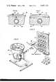
- FIG. 1is a view in elevation of a directionally controlled array of solar power units according to the invention, with the array shown in one of its positions in full lines and in two of its other positions in phantom lines.
- FIG. 2is a greatly enlarged, fragmentary, perspective view of a portion of the apparatus of FIG. 1, showing a portion of the control means for pivoting the power units about a plurality of axes to maintain them pointed at the sun during hours of daylight.
- FIG. 3is a plan view of a directionally powered array of solar power units as shown in FIG. 1.
- FIG. 4is a greatly enlarged, fragmentary, sectional view of one of the power units of the invention.
- FIG. 5is a view in section taken along line 5--5 of FIG. 4.
- FIG. 6is a greatly enlarged, fragmentary view in section taken along line 6--6 in FIG. 4.
- FIG. 7is a greatly enlarged, fragmentary view in section taken along line 7--7 in FIG. 4.
- FIG. 8is a fragmentary, perspective view of a portion of the control means for controlling the position of the solar power units.
- FIG. 9is a perspective view of a modification of the invention, wherein the solar power units are arranged in a vertically oriented array.
- a directionally controlled array of solar power unitsis indicated generally at 10 in FIG. 1 and comprises a pivoted supporting frame 11 on which a plurality of solar power units 12 are pivotally mounted.
- the frame 11is supported for pivotal movement on a base or uprights 13.
- the frame 11 in the embodiment showncomprises a plurality of pipes or conduits connected together to form a peripheral frame portion 14 having a plurality of outwardly extending nipples or fittings 15 and 16 along opposite ends thereof, respectively.
- Elongate, generally rectangularly shaped water manifolds 17comprising a cold water supply pipe 18 and a parallel, spaced hot water pipe 19 converge at their opposite ends and have outwardly extending bosses 20 and 21 thereon engaged on the fittings 15 and 16, respectively.
- the bosses 20 and 21are rotatable upon the fittings 15 and 16 and are sealed relative thereto by means of O-rings or the like interposed therebetween.
- suitable flow blocking means 22are provided in the manifolds 17 to maintain the hot and cold water flows separate from one another, and as seen best in FIGS. 2, 4 and 5, inwardly extending nipples or fittings 23 and 24 are provided on the cold and hot water pipes 18 and 19, respectively, in opposed inwardly directed relationship toward one another.
- the solar power units 12each comprises a base 25 having an inlet bore 26 therein extending inwardly from one side edge of the base to the center thereof and then directly upwardly and opening through an upper surface 27 of the base.
- the inlet bore 26communicates with an outwardly spiraling channel 28 which terminates adjacent the outer edge of the base in a downwardly projecting outlet bore 29, which terminates at its lower end in a laterally projecting passage 30 in diametrically opposed relationship and coaxial with the inlet bore 26.
- the fittings 23 and 24 on the water manifoldsare rotatably received in the bores or passages 26 and 30 and are sealed relative thereto by means of O-rings or the like 31.
- An upstanding, annular wall 32is on the upper surface of the base at the outer marginal edge thereof, and an annular groove 33 is formed in the upper surface spaced radially inwardly from the annular wall 32.
- An O-ring or other suitable seal 34is positioned in the groove 33, and a disc-shaped solar cell 35 is positioned on the upper surface of the base 25 in overlying relationship to the spiral passage 28 and the O-ring 34, and is sealed relative to the base by means of the O-ring.
- a substantially frusto-conically shaped solar concentrator 36is supported on the base and has a radially inturned flange 37 on its lower end, which is bolted to the upstanding peripheral wall 32 by means of bolts or cap screws or the like 38, and the inwardly extending flange overlies the outer peripheral edge portion of the solar cell 35 to clamp it securely downwardly against the O-ring seal 34.
- a groove or channel 39is formed in the upstanding annular wall 32 at one side of the base 25, and a suitable insulated electric lead 40 is disposed in the channel and has its inner exposed end 41 soldered or otherwise suitably secured in electrically conductive relationship with the undersurface of the solar cell 35.
- the inturned flange 37 of the concentrator or cone 36has an upwardly deformed portion 42 therein defining a channel in which another electrical conductor 43 is disposed, with its inner end 44 soldered or otherwise suitable secured in electrically conductive relationship with the upper surface of the solar cell 35.
- a suitable lens 45is suitably secured in the upper end of the frusto-conical concentrator 36 for concentrating the sun's rays on the solar cell 35.
- the frame 11is supported for pivotal movement about its longitudinal axis by means of trunnions or the like 46 and 47 suitably rotatably supported in journals or bearings 48 and 49 at the opposite ends of the frame medially the opposite sides thereof, respectively.
- the frame 11 and the solar power units 12 carried therebyare pivotal about the longitudinal center axis of the frame to a plurality of positions, as seen in FIG. 1.
- the frame and the solar power unitsare shown in a position pointed at the sun during early morning, for example, and in phantom line at 10a, the frame and solar power units are shown in a position pointed at the sun at noontime, for example, and as shown in phantom line at 10b, the array is shown in a position whereat the solar power units are pointed toward the sun in the evening.
- a hydraulic cylinder 50 or other suitable meansis supported on a bracket or the like 51 on the uprights or base 13 and is connected with the frame 11 for moving the frame to its several pivoted positions, as shown in FIG. 1.
- a suitable solenoid valve or the like 52is connected via a pair of supply conduits 53 and 54 with the cylinder 50 for controlling flow of water or other hydraulic fluid thereto from a supply pipe 55.
- a suitable timer mechanism 56is connected with the solenoid valve 52 for operating the valve to move the frame and solar array to the various positions at appropriate times during the day. The timer could be operative to continuously move the platform at a slow rate of movement during the day, or it could be moved in increments, as desired.
- the solar power unitsare pivotally connected about two mutually perpendicular axes, as noted previously, and as seen best in FIG. 2, this is accomplished by pivoting movement of the water manifolds 17 about the bosses 20 and 21 at their opposite ends.
- This pivoting movementis accomplished by means of a suitable hydraulic cylinder or the like 57 connected with an elongate operating bar 58 which is pivotally connected in turn with a plurality of upstanding brackets 59 rigidly secured to the manifolds 17, whereby upon extension and retraction of the piston and cylinder 57 the bar 58 is reciprocated back and forth, thus rocking the arms 59 and causing the manifolds to pivot back and forth about the axes of fittings 15 and 16 at opposite ends of the frame.
- a hydraulic cylinder 60is connected with a link 61 which is connected in turn with a crossbar 62 which has connected thereto a plurality of elongate actuating rods 63 extending the length of the frame and pivotally connected to each solar power unit 12 at one side thereof by means of a projecting lug 64 on the upper end portion of the frusto-conically shaped solar concentrators 36.
- a similar crossbar 65is connected across the actuating rods 63 at the end of the frame opposite the cylinder 60.
- the solar power unitsare effectively ganged together for movement in unison upon actuation of the piston and cylinder assemblies 57 and 60.
- Cylinders 57 and 60are controlled in response to the position of solenoid valves 66 and 67, respectively, which are controlled, in turn, by means of dummy solar power units or solenoid control cones 68 and 69, respectively, each of which has a frusto-conically shaped concentrator 36, just as in the solar power units 12, and a base 25.
- thermocouples or the like 70properly spaced and positioned in the base 25 thereof and a shadow casting element 71 is suitably supported by means of a spider or the like 72 at the upper end of the cone 36, such that in a normal proper position with the cone pointed directly at the sun, all of the thermocouples 70 are in the shadow of the unit 71.
- a spider or the like 72at the upper end of the cone 36, such that in a normal proper position with the cone pointed directly at the sun, all of the thermocouples 70 are in the shadow of the unit 71.
- the thermocoupleswill not fall within the shadow of member 71 and will thus be energized by the sun to cause operation or energization of the solenoids 66 and 67 in an appropriate direction to cause the cone to be pointed at the sun.
- the directionally controlled array of solar power units according to the inventionis automatically positioned in response to movement of the sun in order to maintain the solar collectors or cones thereof pointed directly at the sun at all times during daylight hours to maximize utilization of the sun's energy.
- the heat energy generated from the solar-cellsis utilized to heat water to produce either hot water or steam, depending upon the temperatures attained, and this heated water or steam may thus be utilized for work.
- FIG. 9a modification of the invention is shown, and in this form of the invention a pair of upstanding masts or posts 73 and 74 comprise a frame in which the plurality of manifolds 17 are pivoted for supporting the solar power units 12 in a manner similar to that described in relation to FIGS. 1-8.
- the solar cells 35 in the solar power units 12may be suitably electrically connected with a plurality of batteries or the like 75, if desired, for storing the electrical energy produced thereby for use during hours of darkness.
- the heated water or steam produced as a result of cooling the solar cellsmay be utilized to operate a steam driven electrical generator or the like 76, if desired.
- piston and cylinder assembliesmay be driven or operated by means of the water supplied to the hydraulic system of the invention, or, if desired, they may be operated by means of oil or other suitable motive fluid. For example, they could be pneumatically operated, if desired.
Landscapes
- Engineering & Computer Science (AREA)
- Physics & Mathematics (AREA)
- Life Sciences & Earth Sciences (AREA)
- Sustainable Development (AREA)
- Chemical & Material Sciences (AREA)
- Thermal Sciences (AREA)
- Sustainable Energy (AREA)
- Combustion & Propulsion (AREA)
- Mechanical Engineering (AREA)
- General Engineering & Computer Science (AREA)
- Electromagnetism (AREA)
- General Physics & Mathematics (AREA)
- Radar, Positioning & Navigation (AREA)
- Remote Sensing (AREA)
- Photovoltaic Devices (AREA)
Abstract
Description
This is a continuation, of application Ser. No. 624,396, filed Oct. 21, 1975 now abandoned.
This invention relates to a solar powered means for producing work, and more particularly, relates to such a device which utilizes solar cells for direct conversion of solar energy into electrical energy and also utilizes water circulated in heat exchange relationship with the solar cells to both cool the solar cells and heat the water, whereby the heated water may be used for work.
Specifically, in accordance with the invention, control means are connected with the power units, whereby the power units may be pivoted to maintain them pointed at the sun during daylight hours to thus maximize the amount of solar energy impinging upon the solar cells.
Many devices are known in the prior art for utilizing solar energy to produce work, as exemplified, for example, in some of the U.S. Pat. Nos. listed below:
No. 696,326--De La Garza--Mar. 25, 1902
No. 811,274--A. Carter--Jan. 30, 1906
No. 895,761--F. M. Huntoon--Aug. 11, 1908
No. 1,599,481--A. Marcuse--Sept. 14, 1926
No. 1,658,455--H. Metzech, et al--Feb. 7, 1928
No. 2,552,237--F. Trombe--May 8, 1951
No. 2,946,945--N. J. Regnier, et al--July 26, 1960
No. 3,231,426--F. A. Ludwig, et al--Jan. 25, 1966
No. 3,232,795--R. B. Gillette, et al--Feb. 1, 1966
The prior art devices either do not provide a means for keeping the solar power unit pointed at the sun during daylight hours, or they are excessively complicated and expensive in construction, or they are not energy efficient and thus are not entirely suitable for use.
The present invention solves the problems extant in the prior art by providing a device which utilizes an array of solar power units, each of which has a solar cell therein for directly converting the sun's energy into electrical energy and which also has means for circulation of water in heat exchange relationship with the solar cell to both cool the solar cell and also to produce hot water and/or steam which may then be utilized for work. Control means are connected with the power units for pivoting the power units to maintain them pointed at the sun during hours of daylight to maximize the use of the sun's energy.
Accordingly, it is an object of this invention to provide a directionally controlled array of solar power units, which has means for directly converting the sun's energy into electrical energy and which also has means for simultaneously heating water to thus obtain work therefrom.
Another object of the invention is to provide a directionally controlled array of solar power units which are pivotally supported and are pivotally moved in response to the position of the sun to maintain the units pointed at the sun during hours of daylight to maximize utilization of the sun's energy.
A still further object is to provide a solar power means which utilizes a plurality of solar power units each having a solar cell and a lens for concentrating solar energy on the solar cell, and means for circulating water in heat exchange relationship with the solar cell to heat the water.
Yet another object of the invention is to provide a directionally controlled array of solar power units which is simple and economical in construction and accurate in operation and which is exceptionally energy efficient.
FIG. 1 is a view in elevation of a directionally controlled array of solar power units according to the invention, with the array shown in one of its positions in full lines and in two of its other positions in phantom lines.
FIG. 2 is a greatly enlarged, fragmentary, perspective view of a portion of the apparatus of FIG. 1, showing a portion of the control means for pivoting the power units about a plurality of axes to maintain them pointed at the sun during hours of daylight.
FIG. 3 is a plan view of a directionally powered array of solar power units as shown in FIG. 1.
FIG. 4 is a greatly enlarged, fragmentary, sectional view of one of the power units of the invention.
FIG. 5 is a view in section taken along line 5--5 of FIG. 4.
FIG. 6 is a greatly enlarged, fragmentary view in section taken along line 6--6 in FIG. 4.
FIG. 7 is a greatly enlarged, fragmentary view in section taken alongline 7--7 in FIG. 4.
FIG. 8 is a fragmentary, perspective view of a portion of the control means for controlling the position of the solar power units.
FIG. 9 is a perspective view of a modification of the invention, wherein the solar power units are arranged in a vertically oriented array.
In the drawings, wherein like reference numerals indicate like parts throughout the several views, a directionally controlled array of solar power units is indicated generally at 10 in FIG. 1 and comprises a pivoted supportingframe 11 on which a plurality ofsolar power units 12 are pivotally mounted. Theframe 11 is supported for pivotal movement on a base oruprights 13. Theframe 11 in the embodiment shown comprises a plurality of pipes or conduits connected together to form aperipheral frame portion 14 having a plurality of outwardly extending nipples orfittings water manifolds 17 comprising a coldwater supply pipe 18 and a parallel, spacedhot water pipe 19 converge at their opposite ends and have outwardly extendingbosses fittings bosses fittings manifolds 17 to maintain the hot and cold water flows separate from one another, and as seen best in FIGS. 2, 4 and 5, inwardly extending nipples orfittings hot water pipes
Thesolar power units 12 each comprises abase 25 having an inlet bore 26 therein extending inwardly from one side edge of the base to the center thereof and then directly upwardly and opening through anupper surface 27 of the base. The inlet bore 26 communicates with an outwardlyspiraling channel 28 which terminates adjacent the outer edge of the base in a downwardly projectingoutlet bore 29, which terminates at its lower end in a laterally projectingpassage 30 in diametrically opposed relationship and coaxial with theinlet bore 26. Thefittings passages annular wall 32 is on the upper surface of the base at the outer marginal edge thereof, and anannular groove 33 is formed in the upper surface spaced radially inwardly from theannular wall 32. An O-ring or othersuitable seal 34 is positioned in thegroove 33, and a disc-shapedsolar cell 35 is positioned on the upper surface of thebase 25 in overlying relationship to thespiral passage 28 and the O-ring 34, and is sealed relative to the base by means of the O-ring.
A substantially frusto-conically shapedsolar concentrator 36 is supported on the base and has a radially inturnedflange 37 on its lower end, which is bolted to the upstandingperipheral wall 32 by means of bolts or cap screws or the like 38, and the inwardly extending flange overlies the outer peripheral edge portion of thesolar cell 35 to clamp it securely downwardly against the O-ring seal 34. A groove orchannel 39 is formed in the upstandingannular wall 32 at one side of thebase 25, and a suitable insulatedelectric lead 40 is disposed in the channel and has its inner exposedend 41 soldered or otherwise suitably secured in electrically conductive relationship with the undersurface of thesolar cell 35. Similarly, at the diametrically opposite side of thesolar power unit 12 the inturnedflange 37 of the concentrator orcone 36 has an upwardly deformed portion 42 therein defining a channel in which anotherelectrical conductor 43 is disposed, with itsinner end 44 soldered or otherwise suitable secured in electrically conductive relationship with the upper surface of thesolar cell 35.
Asuitable lens 45 is suitably secured in the upper end of the frusto-conical concentrator 36 for concentrating the sun's rays on thesolar cell 35.
Theframe 11 is supported for pivotal movement about its longitudinal axis by means of trunnions or the like 46 and 47 suitably rotatably supported in journals orbearings frame 11 and thesolar power units 12 carried thereby are pivotal about the longitudinal center axis of the frame to a plurality of positions, as seen in FIG. 1. As illustrated in full lines, the frame and the solar power units are shown in a position pointed at the sun during early morning, for example, and in phantom line at 10a, the frame and solar power units are shown in a position pointed at the sun at noontime, for example, and as shown in phantom line at 10b, the array is shown in a position whereat the solar power units are pointed toward the sun in the evening.
Ahydraulic cylinder 50 or other suitable means is supported on a bracket or the like 51 on the uprights orbase 13 and is connected with theframe 11 for moving the frame to its several pivoted positions, as shown in FIG. 1. A suitable solenoid valve or the like 52 is connected via a pair ofsupply conduits cylinder 50 for controlling flow of water or other hydraulic fluid thereto from asupply pipe 55. Asuitable timer mechanism 56 is connected with thesolenoid valve 52 for operating the valve to move the frame and solar array to the various positions at appropriate times during the day. The timer could be operative to continuously move the platform at a slow rate of movement during the day, or it could be moved in increments, as desired.
In addition to pivoting movement of the frame, the solar power units are pivotally connected about two mutually perpendicular axes, as noted previously, and as seen best in FIG. 2, this is accomplished by pivoting movement of thewater manifolds 17 about thebosses elongate operating bar 58 which is pivotally connected in turn with a plurality ofupstanding brackets 59 rigidly secured to themanifolds 17, whereby upon extension and retraction of the piston andcylinder 57 thebar 58 is reciprocated back and forth, thus rocking thearms 59 and causing the manifolds to pivot back and forth about the axes offittings solar power units 12 are mounted for pivotal movement about the axes offittings hydraulic cylinder 60 is connected with alink 61 which is connected in turn with acrossbar 62 which has connected thereto a plurality ofelongate actuating rods 63 extending the length of the frame and pivotally connected to eachsolar power unit 12 at one side thereof by means of a projectinglug 64 on the upper end portion of the frusto-conically shapedsolar concentrators 36. Asimilar crossbar 65 is connected across the actuatingrods 63 at the end of the frame opposite thecylinder 60. Thus, the solar power units are effectively ganged together for movement in unison upon actuation of the piston andcylinder assemblies Cylinders solenoid valves solenoid control cones concentrator 36, just as in thesolar power units 12, and abase 25. However, rather than thesolar cells 35, theseunits base 25 thereof and ashadow casting element 71 is suitably supported by means of a spider or the like 72 at the upper end of thecone 36, such that in a normal proper position with the cone pointed directly at the sun, all of thethermocouples 70 are in the shadow of theunit 71. However, whenever thecone 36 is not pointed directly at the sun, one or the other of the thermocouples will not fall within the shadow ofmember 71 and will thus be energized by the sun to cause operation or energization of thesolenoids
Thus, the directionally controlled array of solar power units according to the invention is automatically positioned in response to movement of the sun in order to maintain the solar collectors or cones thereof pointed directly at the sun at all times during daylight hours to maximize utilization of the sun's energy. Moreover, the heat energy generated from the solar-cells is utilized to heat water to produce either hot water or steam, depending upon the temperatures attained, and this heated water or steam may thus be utilized for work.
In FIG. 9 a modification of the invention is shown, and in this form of the invention a pair of upstanding masts orposts manifolds 17 are pivoted for supporting thesolar power units 12 in a manner similar to that described in relation to FIGS. 1-8. Thesolar cells 35 in thesolar power units 12 may be suitably electrically connected with a plurality of batteries or the like 75, if desired, for storing the electrical energy produced thereby for use during hours of darkness. The heated water or steam produced as a result of cooling the solar cells may be utilized to operate a steam driven electrical generator or the like 76, if desired.
As noted previously, the piston and cylinder assemblies may be driven or operated by means of the water supplied to the hydraulic system of the invention, or, if desired, they may be operated by means of oil or other suitable motive fluid. For example, they could be pneumatically operated, if desired.
It is apparent that a directionally controlled array of solar power units in accordance with the invention could be provided with hundreds of power units to thus produce large amounts of power in a relatively small amount of space, particularly in view of the use oflenses 45 to concentrate the sun's energy on thesolar cells 35.
As this invention may be embodied in several forms without departing from the spirit or essential characteristics thereof, the present embodiment is, therefore, illustrative and not restrictive, since the scope of the invention is defined by the appended claims rather than by the description preceding them, and all changes that fall within the metes and bounds of the claims or that form their functional as well as conjointly cooperative equivalents are, therefore, intended to be embraced by those claims.
Claims (8)
1. A directionally controlled array of solar power units, comprising: a pivotal supporting frame; a plurality of solar power units pivotally mounted on the frame for pivotal movement about two mutually perpendicular axes; conduit means on the frame for flow of cold water to and hot water from each power unit; each power unit including a solar cell for direct conversion of solar energy into electrical energy; lens means on each power unit arranged to concentrate solar energy on the solar cell of that unit; said conduit means connected for flow of cold water in heat exchange relationship with the solar cells to cool the solar cells and heat the water, said hot water thus being available for work; each power unit further comprising a base having a top surface and a bottom surface, an inlet into said base and extending through said base and exiting outwardly through the top surface of the base, a serpentine, open fluid flow troughlike passageway defined in said base top surface and extending from the inlet and a passage extending from the passageway downwardly into the base and thence outwardly through said base, said solar cell overlying the passageway closing the open side thereof to confine fluid flow through the passageway with said fluid contacting one side of said solar cell; and control means connected with the power units and the frame to pivot the power units in response to the position of the sun to keep the power units pointed at the sun during hours of daylight.
2. A solar array as in claim 1, wherein the supporting frame is rectangular in shape and includes opposite ends and opposite sides, said frame comprising a plurality of joined together, elongate pipes, outwardly extending journals on the pipes at the opposite ends of the frames medially of the opposite ends supported in bearing means for pivotal movement of the frame from side to side about the longitudinal axis thereof, said conduit means including a plurality of pairs of spaced apart, parallel hot and cold water pipes extending parallel to the sides of the frame and substantially coextensive in length therewith, said pipes converging at their opposite ends and having projecting fittings thereon rotatably received in cooperating bosses on confronting inner surfaces of the opposite ends of the frame, whereby said hot and cold pipes are disposed in pairs and are pivotally supported at opposite ends of the frame for pivotal movement about axes extending parallel to the pivotal axis of the frame.
3. A solar array as in claim 1, wherein said control means includes a plurality of thermocouple means, means spaced from the thermocouple means normally shading the thermocouple means, said thermocouple means supported in a housing carried by the frame and movable with the power units, whereby the housing is oriented identically to the orientation of the power units, and power means connected with the frame and power units and responsive to energization of the thermocouple means to pivot the frame and power units to maintain the power units pointed at the sun and to maintain the thermocouples in the shade.
4. A solar array as in claim 2, wherein power means is connected with the frame and with the power units for pivoting the frame and power units to maintain the power units pointed at the sun during hours of daylight, said power means comprising hydraulic piston and cylinder assemblies and link means connected between the piston and cylinder assemblies and the frame and power units to pivot the frame and power units in response to extension and retraction of the piston and cylinder assemblies, said control means comprising solenoid valves connected between the pipes of the frame for receiving water therefrom and the piston and cylinder assemblies for controlling flow of water from the frame pipes to the piston and cylinder assemblies.
5. A solar array as in claim 4, wherein said control means comprises a housing mounted on the frame for movement in unison with said power units, a plurality of thermocouple means carried by the housing means and means carried by the housing means for shading the thermocouple means when the housing means and power units are pointed directly at the sun, such that when the power units and housing means are not pointed directly at the sun, one or more of the thermocouple means is exposed to the sun to thus energize the solenoid valve means to operate the piston and cylinder assemblies to orient the power units and housing means to maintain them pointed at the sun.
6. A solar array as in claim 1, wherein the solar cells are electrically connected with a plurality of storage batteries for storing electrical energy produced thereby during hours of daylight for subsequent use of the electrical energy during hours of darkness.
7. A solar array as in claim 6, wherein the hot water outlet from the power units is connected with suitable power means for producing work.
8. A solar array as in claim 5, wherein said base is substantially circular, and said inlet is defined on one side thereof and exits upwardly at the center thereof, and further wherein said fluid flow passageway is spiral shaped and has an exit passage adjacent the outer periphery of said base located diametrically opposite said inlet, and further including a conically-shaped solar concentrator supported on the base above the solar cell and having lens means carried thereby for concentrating the sun's energy on the solar cell to produce electrical energy therefrom, said cold water pipe connected with the inlet to the base for circulation of cold water into the base and through the spirally-shaped passageway to heat the water.
Priority Applications (1)
| Application Number | Priority Date | Filing Date | Title |
|---|---|---|---|
| US05/851,718US4187123A (en) | 1975-10-21 | 1977-11-15 | Directionally controlled array of solar power units |
Applications Claiming Priority (2)
| Application Number | Priority Date | Filing Date | Title |
|---|---|---|---|
| US62439675A | 1975-10-21 | 1975-10-21 | |
| US05/851,718US4187123A (en) | 1975-10-21 | 1977-11-15 | Directionally controlled array of solar power units |
Related Parent Applications (1)
| Application Number | Title | Priority Date | Filing Date |
|---|---|---|---|
| US62439675AContinuation | 1975-10-21 | 1975-10-21 |
Publications (1)
| Publication Number | Publication Date |
|---|---|
| US4187123Atrue US4187123A (en) | 1980-02-05 |
Family
ID=27089676
Family Applications (1)
| Application Number | Title | Priority Date | Filing Date |
|---|---|---|---|
| US05/851,718Expired - LifetimeUS4187123A (en) | 1975-10-21 | 1977-11-15 | Directionally controlled array of solar power units |
Country Status (1)
| Country | Link |
|---|---|
| US (1) | US4187123A (en) |
Cited By (91)
| Publication number | Priority date | Publication date | Assignee | Title |
|---|---|---|---|---|
| FR2452792A1 (en)* | 1979-03-30 | 1980-10-24 | Fiat Ricerche | MODULAR UNIT FOR THE CONVERSION OF SOLAR ENERGY |
| US4307711A (en)* | 1980-02-25 | 1981-12-29 | Doundoulakis George J | Sun tracking solar energy collector system |
| US4323052A (en)* | 1979-01-05 | 1982-04-06 | Virgil Stark | Solar energy system |
| US4328789A (en)* | 1976-11-22 | 1982-05-11 | American Solar | Solar tracking drive mechanism |
| US4398053A (en)* | 1978-12-26 | 1983-08-09 | Orillion Alfred G | Pyramidal energy collector |
| US4397303A (en)* | 1981-02-09 | 1983-08-09 | Armco Inc. | Heat exchanger for concentrating solar collectors and method for making the heat exchanger |
| US4410757A (en)* | 1982-03-22 | 1983-10-18 | Monegon, Ltd. | Adjustable collection members for solar energy systems |
| US4459972A (en)* | 1981-10-06 | 1984-07-17 | Veda Incorporated | Heliostat assembly |
| FR2546337A1 (en)* | 1983-05-19 | 1984-11-23 | Electricite De France | Device for orienting solar panels |
| US4572161A (en)* | 1983-06-24 | 1986-02-25 | Kei Mori | Solar ray collector device |
| US4575639A (en)* | 1980-12-16 | 1986-03-11 | Rogow Bruce I | Fluid turbine system |
| EP0136712A3 (en)* | 1983-10-04 | 1986-04-30 | Kei Mori | A solar ray collecting device for use in space |
| EP0128395A3 (en)* | 1983-06-03 | 1986-05-14 | Kei Mori | Solar ray collecting device |
| US4601282A (en)* | 1984-07-12 | 1986-07-22 | Total Solar Energy Systems, Inc. | Automatic solar collector system |
| US4619244A (en)* | 1983-03-25 | 1986-10-28 | Marks Alvin M | Solar heater with cavity and phase-change material |
| US4750943A (en)* | 1986-02-28 | 1988-06-14 | Tpv Energy Systems, Inc. | Thermophotovoltaic system |
| EP0130445B1 (en)* | 1983-06-24 | 1988-12-14 | Kei Mori | Solar ray collecting device |
| US4995377A (en)* | 1990-06-29 | 1991-02-26 | Eiden Glenn E | Dual axis solar collector assembly |
| WO1992020893A1 (en)* | 1991-05-13 | 1992-11-26 | Kroetz Thomas | Anti-dazzle device for buildings |
| DE4309259A1 (en)* | 1993-03-16 | 1994-09-29 | Kranz Reinhard Otto Dipl Ing D | Solar panel support for solar tracking of solar-panel cam panel |
| EP0897090A1 (en)* | 1997-08-13 | 1999-02-17 | Josef Mayrhofer | Solar system |
| US6058930A (en)* | 1999-04-21 | 2000-05-09 | Shingleton; Jefferson | Solar collector and tracker arrangement |
| US6079408A (en)* | 1998-03-30 | 2000-06-27 | Honda Giken Kogyo Kabushiki Kaisha | Sun-ray tracking system |
| DE10022236A1 (en)* | 2000-05-08 | 2001-11-15 | Grollius Horst Walter | Mechanical and hydraulic positioning system for two axis solar generator includes toothed rod for adjustment about first axis, and hydraulic cylinder gives motion about second axis |
| WO2002080286A1 (en)* | 2001-03-28 | 2002-10-10 | Solar Systems Pty Ltd | Cooling circuit for receiver of solar radiation |
| US20030172922A1 (en)* | 2000-01-27 | 2003-09-18 | Haber Michael B | Solar panel tilt mechanism |
| US20040238025A1 (en)* | 2003-03-18 | 2004-12-02 | Powerlight Corporation, A California Corporation | Tracking solar collector assembly |
| US20060044511A1 (en)* | 2004-08-10 | 2006-03-02 | Mackamul Kevin K | Tracker drive system and solar energy collection system |
| US7109461B2 (en) | 2001-03-28 | 2006-09-19 | Solar Systems Pty Ltd. | Solar tracking system |
| US20060266408A1 (en)* | 2005-05-26 | 2006-11-30 | Horne Stephen J | Concentrator solar photovoltaic array with compact tailored imaging power units |
| US20060283497A1 (en)* | 2005-06-16 | 2006-12-21 | Hines Braden E | Planar concentrating photovoltaic solar panel with individually articulating concentrator elements |
| DE102005047132A1 (en)* | 2005-09-30 | 2007-04-12 | Solartec Ag | Concentrator photovoltaic device; Photovoltaic device for use therein and manufacturing method therefor |
| US20070102037A1 (en)* | 2005-10-04 | 2007-05-10 | Irwin Philip C | Self-powered systems and methods using auxiliary solar cells |
| US20070188876A1 (en)* | 2006-01-17 | 2007-08-16 | Hines Braden E | Hybrid primary optical component for optical concentrators |
| US20070193620A1 (en)* | 2006-01-17 | 2007-08-23 | Hines Braden E | Concentrating solar panel and related systems and methods |
| WO2007098734A2 (en) | 2006-02-28 | 2007-09-07 | Conergy Ag | Tracking support for solar modules |
| US20070215145A1 (en)* | 2005-07-18 | 2007-09-20 | Arizona Public Service Company | System for Supporting Energy Conversion Modules |
| DE102006024450A1 (en)* | 2006-05-24 | 2007-11-29 | Climasol Solartechnik Gmbh | Solar power plant for generating electrical energy and heat energy, has module support with shoe that is connected with foot using rotary hinge, and module field carrier fastened to mounting section of shoe |
| WO2008025234A1 (en)* | 2006-08-18 | 2008-03-06 | Ge Pan | Special platform for generating electricity using solar energy |
| US20080072952A1 (en)* | 2006-09-21 | 2008-03-27 | Chen-Sung Liao | Angle-adjustable solar energy device |
| US20080128586A1 (en)* | 2006-10-13 | 2008-06-05 | Johnson Richard L | Sun sensor assembly and related method of using |
| US20080135096A1 (en)* | 2006-09-30 | 2008-06-12 | Johnson Richard L | Optical concentrators having one or more line foci and related methods |
| WO2008096193A1 (en)* | 2007-02-05 | 2008-08-14 | Claudio Londero | System for producing energy with solar panels |
| US20080283116A1 (en)* | 2007-05-17 | 2008-11-20 | Solergy, Inc. | Light energy conversion systems and methods |
| US20090000662A1 (en)* | 2007-03-11 | 2009-01-01 | Harwood Duncan W J | Photovoltaic receiver for solar concentrator applications |
| US20090032090A1 (en)* | 2007-07-30 | 2009-02-05 | Emcore Corporation | Method for assembling a terrestrial solar array including a rigid support frame |
| US20090032086A1 (en)* | 2007-07-30 | 2009-02-05 | Emcore Corporation | Terrestrial solar array including a rigid support frame |
| US20090064994A1 (en)* | 2005-05-13 | 2009-03-12 | Clive Keith Weatherby | Concentrating solar collector |
| US20090086348A1 (en)* | 2007-10-01 | 2009-04-02 | Jinchun Xie | System for simultaneously turning and tilting an array of mirror concentrators |
| EP2051306A1 (en)* | 2007-10-15 | 2009-04-22 | Beghelli S.p.A. | Photovoltaic generator with solar tracking integrated into support structure |
| US20090120016A1 (en)* | 2007-11-08 | 2009-05-14 | Wai Man Hon | Solar Panel Supporting System |
| US7550054B2 (en) | 2001-03-28 | 2009-06-23 | Solar Systems Pty Ltd. | Method of manufacturing mirrors for a dish reflector |
| US20090159075A1 (en)* | 2007-11-20 | 2009-06-25 | Regenesis Power, Llc. | Southerly tilted solar tracking system and method |
| US7557292B2 (en) | 2003-03-10 | 2009-07-07 | Sunpower Corporation, Systems | Modular shade system with solar tracking panels |
| US20090223510A1 (en)* | 2006-11-22 | 2009-09-10 | Larsen Theodore E | Optimized solar collector |
| DE102008020815A1 (en)* | 2008-03-14 | 2009-10-15 | Ersol Solar Energy Ag | Photovoltaic solar module |
| WO2009152343A1 (en)* | 2008-06-12 | 2009-12-17 | Solergy, Inc. | Methods, systems, and apparatuses for aligning light concentrator components with a light source |
| US20100018570A1 (en)* | 2008-05-16 | 2010-01-28 | Cashion Steven A | Concentrating photovoltaic solar panel |
| ES2334187A1 (en)* | 2006-10-03 | 2010-03-05 | Manuel Lahuerta Romeo | Solar follower of three axes of great surface (Machine-translation by Google Translate, not legally binding) |
| US20100102202A1 (en)* | 2008-10-24 | 2010-04-29 | Emcore Solar Power, Inc, | Solar Tracking for Terrestrial Solar Arrays with Variable Start and Stop Positions |
| US20100108860A1 (en)* | 2008-10-24 | 2010-05-06 | Emcore Solar Power, Inc. | Techniques for Monitoring Solar Array Performance and Applications Thereof |
| WO2010072871A1 (en)* | 2008-12-24 | 2010-07-01 | Global Solar Fund Partners Sarl | Solar tracking device for panels |
| US20100307563A1 (en)* | 2005-04-27 | 2010-12-09 | Ricard Pardell Vilella | Sub-Module for Photovoltaic Concentration Modules, Photovoltaic Concentration Module, Solar Power Installation, Packing Method and Position Calibration Method for Photovoltaic Concentration Modules |
| US20110046789A1 (en)* | 2007-10-01 | 2011-02-24 | Koninklijke Philips Electronics N.V. | Building management system with active building skin, an environmental resource collector for use in such a system and a method of managing resources used in a building |
| WO2011044358A1 (en)* | 2009-10-07 | 2011-04-14 | Robert Orsello | System and method for heat rejection in a solar power collection system |
| US20110139145A1 (en)* | 2004-08-10 | 2011-06-16 | Kevin Keith Mackamul | Tracker drive system and solar energy collection system |
| US20110146752A1 (en)* | 2009-12-22 | 2011-06-23 | Jongho Park | Solar module and solar array |
| US20110214712A1 (en)* | 2008-08-06 | 2011-09-08 | Scott Frazier | Solar energy conversion |
| US20110265873A1 (en)* | 2009-07-13 | 2011-11-03 | Seung-Seop Kim | Photovoltaic power-generating apparatus |
| US8101849B2 (en) | 2007-03-23 | 2012-01-24 | Sunpower Corporation | Tilt assembly for tracking solar collector assembly |
| WO2012040779A1 (en)* | 2010-09-28 | 2012-04-05 | Solagen Pty Ltd | Receiver |
| ITPD20100296A1 (en)* | 2010-10-07 | 2012-04-08 | Lamo Srl | LOCKING SYSTEM FOR PANELS MOUNTED ON TRACKERS |
| US20120180780A1 (en)* | 2011-01-14 | 2012-07-19 | Hsien-Te Tseng | Solar panel sun-tracing equipment |
| US20120291374A1 (en)* | 2011-05-16 | 2012-11-22 | Anthony Zante | Long span solar collector support system |
| US20120299529A1 (en)* | 2009-12-31 | 2012-11-29 | Guo Guangxi | Solar charger for charging power battery |
| WO2012123975A3 (en)* | 2011-03-14 | 2012-12-20 | D.G. Energy Srl | Photovoltaic panel provided with orientable solar-tracking photovoltaic cells |
| US20130186451A1 (en)* | 2013-01-23 | 2013-07-25 | Nathaniel Tanti | Off-angle Tracker |
| US20140166077A1 (en)* | 2012-12-17 | 2014-06-19 | Skyven Technologies, LLC | Solar concentration system |
| AU2008262186B2 (en)* | 2007-05-17 | 2014-08-07 | Solergy, Inc. | Light energy conversion systems and methods |
| US9200452B2 (en) | 2012-09-20 | 2015-12-01 | Mbc Ventures, Inc. | Controller for skylight energy management system |
| US9287430B1 (en)* | 2007-11-01 | 2016-03-15 | Sandia Corporation | Photovoltaic solar concentrator |
| US20160195303A1 (en)* | 2015-01-05 | 2016-07-07 | Sunpower Corporation | Solar tracker drive mount |
| US9391557B2 (en) | 2013-03-15 | 2016-07-12 | Sandia Corporation | Solar tracking system |
| US9528724B1 (en) | 2011-06-08 | 2016-12-27 | Solarreserve Technology, Llc | Apparatus and method for configuring heliostat fields |
| US20170284705A1 (en)* | 2014-09-03 | 2017-10-05 | Jan Sehnoutek | Device for the Utilization of Solar Energy |
| US10044319B2 (en) | 2013-03-29 | 2018-08-07 | Anthony A. Zante | Elevated long span solar panel mounting system |
| US10116253B2 (en)* | 2013-10-10 | 2018-10-30 | Lg Innotek Co., Ltd. | Solar power generating device |
| US10778140B2 (en)* | 2015-09-14 | 2020-09-15 | Soltec Energías Renovables, S.L. | Device for capturing solar energy |
| CN111717415A (en)* | 2020-06-22 | 2020-09-29 | 中国科学院微小卫星创新研究院 | A sun-tracking method for constellation satellite solar cell array |
| US10879836B2 (en)* | 2018-03-27 | 2020-12-29 | Preformed Line Products Co. | Mounting assembly for mounting a solar panel |
| US12235044B1 (en)* | 2024-07-12 | 2025-02-25 | Guangdong Ocean University | Heat-collecting forage drying system with wind-solar complementary energy supply |
Citations (3)
| Publication number | Priority date | Publication date | Assignee | Title |
|---|---|---|---|---|
| FR909092A (en)* | 1944-09-19 | 1946-04-29 | Equipment intended for the heating of liquids by solar rays | |
| US3965683A (en)* | 1974-05-09 | 1976-06-29 | Sydney Dix | Solar electrical generating system |
| US3976508A (en)* | 1974-11-01 | 1976-08-24 | Mobil Tyco Solar Energy Corporation | Tubular solar cell devices |
- 1977
- 1977-11-15USUS05/851,718patent/US4187123A/ennot_activeExpired - Lifetime
Patent Citations (3)
| Publication number | Priority date | Publication date | Assignee | Title |
|---|---|---|---|---|
| FR909092A (en)* | 1944-09-19 | 1946-04-29 | Equipment intended for the heating of liquids by solar rays | |
| US3965683A (en)* | 1974-05-09 | 1976-06-29 | Sydney Dix | Solar electrical generating system |
| US3976508A (en)* | 1974-11-01 | 1976-08-24 | Mobil Tyco Solar Energy Corporation | Tubular solar cell devices |
Cited By (146)
| Publication number | Priority date | Publication date | Assignee | Title |
|---|---|---|---|---|
| US4328789A (en)* | 1976-11-22 | 1982-05-11 | American Solar | Solar tracking drive mechanism |
| US4398053A (en)* | 1978-12-26 | 1983-08-09 | Orillion Alfred G | Pyramidal energy collector |
| US4323052A (en)* | 1979-01-05 | 1982-04-06 | Virgil Stark | Solar energy system |
| FR2452792A1 (en)* | 1979-03-30 | 1980-10-24 | Fiat Ricerche | MODULAR UNIT FOR THE CONVERSION OF SOLAR ENERGY |
| US4280853A (en)* | 1979-03-30 | 1981-07-28 | Centro Ricerche Fiat S.P.A. | Solar energy conversion unit |
| US4307711A (en)* | 1980-02-25 | 1981-12-29 | Doundoulakis George J | Sun tracking solar energy collector system |
| US4575639A (en)* | 1980-12-16 | 1986-03-11 | Rogow Bruce I | Fluid turbine system |
| US4397303A (en)* | 1981-02-09 | 1983-08-09 | Armco Inc. | Heat exchanger for concentrating solar collectors and method for making the heat exchanger |
| US4459972A (en)* | 1981-10-06 | 1984-07-17 | Veda Incorporated | Heliostat assembly |
| US4410757A (en)* | 1982-03-22 | 1983-10-18 | Monegon, Ltd. | Adjustable collection members for solar energy systems |
| US4619244A (en)* | 1983-03-25 | 1986-10-28 | Marks Alvin M | Solar heater with cavity and phase-change material |
| FR2546337A1 (en)* | 1983-05-19 | 1984-11-23 | Electricite De France | Device for orienting solar panels |
| EP0128395A3 (en)* | 1983-06-03 | 1986-05-14 | Kei Mori | Solar ray collecting device |
| EP0130445B1 (en)* | 1983-06-24 | 1988-12-14 | Kei Mori | Solar ray collecting device |
| EP0130486B1 (en)* | 1983-06-24 | 1989-05-17 | Kei Mori | Solar ray collector device |
| US4572161A (en)* | 1983-06-24 | 1986-02-25 | Kei Mori | Solar ray collector device |
| EP0136712A3 (en)* | 1983-10-04 | 1986-04-30 | Kei Mori | A solar ray collecting device for use in space |
| AU575075B2 (en)* | 1983-10-04 | 1988-07-21 | Kei Mori | Solar ray collecting device |
| US4601282A (en)* | 1984-07-12 | 1986-07-22 | Total Solar Energy Systems, Inc. | Automatic solar collector system |
| US4750943A (en)* | 1986-02-28 | 1988-06-14 | Tpv Energy Systems, Inc. | Thermophotovoltaic system |
| US4995377A (en)* | 1990-06-29 | 1991-02-26 | Eiden Glenn E | Dual axis solar collector assembly |
| WO1992020893A1 (en)* | 1991-05-13 | 1992-11-26 | Kroetz Thomas | Anti-dazzle device for buildings |
| DE4309259A1 (en)* | 1993-03-16 | 1994-09-29 | Kranz Reinhard Otto Dipl Ing D | Solar panel support for solar tracking of solar-panel cam panel |
| EP0897090A1 (en)* | 1997-08-13 | 1999-02-17 | Josef Mayrhofer | Solar system |
| WO1999009356A1 (en)* | 1997-08-13 | 1999-02-25 | Josef Mayrhofer | Solar plant |
| US6079408A (en)* | 1998-03-30 | 2000-06-27 | Honda Giken Kogyo Kabushiki Kaisha | Sun-ray tracking system |
| US6058930A (en)* | 1999-04-21 | 2000-05-09 | Shingleton; Jefferson | Solar collector and tracker arrangement |
| US6848442B2 (en)* | 2000-01-27 | 2005-02-01 | Michael B. Haber | Solar panel tilt mechanism |
| US20030172922A1 (en)* | 2000-01-27 | 2003-09-18 | Haber Michael B | Solar panel tilt mechanism |
| DE10022236A1 (en)* | 2000-05-08 | 2001-11-15 | Grollius Horst Walter | Mechanical and hydraulic positioning system for two axis solar generator includes toothed rod for adjustment about first axis, and hydraulic cylinder gives motion about second axis |
| DE10022236B4 (en)* | 2000-05-08 | 2005-09-01 | Grollius, Horst-Walter, Dr.-Ing. | Mechanical / hydraulic adjustment system for biaxial solar generators tracking the position of the sun |
| US7109461B2 (en) | 2001-03-28 | 2006-09-19 | Solar Systems Pty Ltd. | Solar tracking system |
| US7076965B2 (en) | 2001-03-28 | 2006-07-18 | John Beavis Lasich | Cooling circuit for receiver of solar radiation |
| WO2002080286A1 (en)* | 2001-03-28 | 2002-10-10 | Solar Systems Pty Ltd | Cooling circuit for receiver of solar radiation |
| US20040103680A1 (en)* | 2001-03-28 | 2004-06-03 | Lasich John Beavis | Cooling circuit for reciever of solar radiation |
| US7550054B2 (en) | 2001-03-28 | 2009-06-23 | Solar Systems Pty Ltd. | Method of manufacturing mirrors for a dish reflector |
| US7888587B2 (en) | 2003-03-10 | 2011-02-15 | Sunpower Corporation, Systems | Modular shade system with solar tracking panels |
| US7557292B2 (en) | 2003-03-10 | 2009-07-07 | Sunpower Corporation, Systems | Modular shade system with solar tracking panels |
| US20090223142A1 (en)* | 2003-03-10 | 2009-09-10 | Sunpower Corporation, Systems | Modular Shade System with Solar Tracking Panels |
| US7888588B2 (en) | 2003-03-18 | 2011-02-15 | Sunpower Corporation, Systems | Tracking solar collector assembly |
| US20090235975A1 (en)* | 2003-03-18 | 2009-09-24 | Sunpower Corporation, Systems | Tracking Solar Collector Assembly |
| WO2004083741A3 (en)* | 2003-03-18 | 2005-07-28 | Powerlight Corp | Tracking solar collector assembly |
| US7554030B2 (en) | 2003-03-18 | 2009-06-30 | Sunpower Corporation, Systems | Tracking solar collector assembly |
| US20040238025A1 (en)* | 2003-03-18 | 2004-12-02 | Powerlight Corporation, A California Corporation | Tracking solar collector assembly |
| US8704081B2 (en)* | 2004-05-17 | 2014-04-22 | Solergy, Inc. | Light energy conversion systems and methods |
| US20110139145A1 (en)* | 2004-08-10 | 2011-06-16 | Kevin Keith Mackamul | Tracker drive system and solar energy collection system |
| US7836879B2 (en)* | 2004-08-10 | 2010-11-23 | Kevin Keith Mackamul | Tracker drive system and solar energy collection system |
| US8807129B2 (en) | 2004-08-10 | 2014-08-19 | Kevin Keith Mackamul | Tracker drive system and solar energy collection system |
| US20060044511A1 (en)* | 2004-08-10 | 2006-03-02 | Mackamul Kevin K | Tracker drive system and solar energy collection system |
| US20100307563A1 (en)* | 2005-04-27 | 2010-12-09 | Ricard Pardell Vilella | Sub-Module for Photovoltaic Concentration Modules, Photovoltaic Concentration Module, Solar Power Installation, Packing Method and Position Calibration Method for Photovoltaic Concentration Modules |
| US20090064994A1 (en)* | 2005-05-13 | 2009-03-12 | Clive Keith Weatherby | Concentrating solar collector |
| US8063300B2 (en) | 2005-05-26 | 2011-11-22 | Solfocus, Inc. | Concentrator solar photovoltaic array with compact tailored imaging power units |
| US20070089778A1 (en)* | 2005-05-26 | 2007-04-26 | Horne Stephen J | Concentrator solar photovol taic array with compact tailored imaging power units |
| US20060266408A1 (en)* | 2005-05-26 | 2006-11-30 | Horne Stephen J | Concentrator solar photovoltaic array with compact tailored imaging power units |
| WO2006130520A3 (en)* | 2005-05-26 | 2009-04-16 | Solfocus Inc | Concentrator solar photovoltaic array with compact tailored imaging power units |
| US20090283134A1 (en)* | 2005-06-16 | 2009-11-19 | Hines Braden E | Concentrating photovoltaic solar panel having one or more concentrator modules or module groups that articulate in place |
| US20060283497A1 (en)* | 2005-06-16 | 2006-12-21 | Hines Braden E | Planar concentrating photovoltaic solar panel with individually articulating concentrator elements |
| US7622666B2 (en) | 2005-06-16 | 2009-11-24 | Soliant Energy Inc. | Photovoltaic concentrator modules and systems having a heat dissipating element located within a volume in which light rays converge from an optical concentrating element towards a photovoltaic receiver |
| US20070215145A1 (en)* | 2005-07-18 | 2007-09-20 | Arizona Public Service Company | System for Supporting Energy Conversion Modules |
| DE102005047132A1 (en)* | 2005-09-30 | 2007-04-12 | Solartec Ag | Concentrator photovoltaic device; Photovoltaic device for use therein and manufacturing method therefor |
| US20090308431A1 (en)* | 2005-09-30 | 2009-12-17 | Solartec Ag | Concentrator photovoltaic device; photovoltaic unit for use therein and manufacturing method for this |
| US20070102037A1 (en)* | 2005-10-04 | 2007-05-10 | Irwin Philip C | Self-powered systems and methods using auxiliary solar cells |
| US20070188876A1 (en)* | 2006-01-17 | 2007-08-16 | Hines Braden E | Hybrid primary optical component for optical concentrators |
| US20070193620A1 (en)* | 2006-01-17 | 2007-08-23 | Hines Braden E | Concentrating solar panel and related systems and methods |
| WO2007084517A3 (en)* | 2006-01-17 | 2008-02-21 | Soliant Energy Inc | Concentrating solar panel and related systems and methods |
| US7688525B2 (en) | 2006-01-17 | 2010-03-30 | Soliant Energy, Inc. | Hybrid primary optical component for optical concentrators |
| WO2007098734A2 (en) | 2006-02-28 | 2007-09-07 | Conergy Ag | Tracking support for solar modules |
| WO2007098734A3 (en)* | 2006-02-28 | 2007-10-18 | Conergy Ag | Tracking support for solar modules |
| DE102006024450A1 (en)* | 2006-05-24 | 2007-11-29 | Climasol Solartechnik Gmbh | Solar power plant for generating electrical energy and heat energy, has module support with shoe that is connected with foot using rotary hinge, and module field carrier fastened to mounting section of shoe |
| WO2008025234A1 (en)* | 2006-08-18 | 2008-03-06 | Ge Pan | Special platform for generating electricity using solar energy |
| US20080072952A1 (en)* | 2006-09-21 | 2008-03-27 | Chen-Sung Liao | Angle-adjustable solar energy device |
| US20080135096A1 (en)* | 2006-09-30 | 2008-06-12 | Johnson Richard L | Optical concentrators having one or more line foci and related methods |
| US20080142078A1 (en)* | 2006-09-30 | 2008-06-19 | Johnson Richard L | Optical concentrators having one or more spot focus and related methods |
| ES2334187B1 (en)* | 2006-10-03 | 2010-09-14 | Manuel Lahuerta Romeo | SOLAR FOLLOWER OF THREE AXLES OF LARGE SURFACE. |
| ES2334187A1 (en)* | 2006-10-03 | 2010-03-05 | Manuel Lahuerta Romeo | Solar follower of three axes of great surface (Machine-translation by Google Translate, not legally binding) |
| US20080128586A1 (en)* | 2006-10-13 | 2008-06-05 | Johnson Richard L | Sun sensor assembly and related method of using |
| US20090223510A1 (en)* | 2006-11-22 | 2009-09-10 | Larsen Theodore E | Optimized solar collector |
| WO2008096193A1 (en)* | 2007-02-05 | 2008-08-14 | Claudio Londero | System for producing energy with solar panels |
| US20090000662A1 (en)* | 2007-03-11 | 2009-01-01 | Harwood Duncan W J | Photovoltaic receiver for solar concentrator applications |
| US9243818B2 (en) | 2007-03-23 | 2016-01-26 | Sunpower Corporation | Stackable tracking solar collector assembly |
| US8101849B2 (en) | 2007-03-23 | 2012-01-24 | Sunpower Corporation | Tilt assembly for tracking solar collector assembly |
| US20080283116A1 (en)* | 2007-05-17 | 2008-11-20 | Solergy, Inc. | Light energy conversion systems and methods |
| AU2008262186B2 (en)* | 2007-05-17 | 2014-08-07 | Solergy, Inc. | Light energy conversion systems and methods |
| US20090032090A1 (en)* | 2007-07-30 | 2009-02-05 | Emcore Corporation | Method for assembling a terrestrial solar array including a rigid support frame |
| US20090032086A1 (en)* | 2007-07-30 | 2009-02-05 | Emcore Corporation | Terrestrial solar array including a rigid support frame |
| US9348328B2 (en) | 2007-10-01 | 2016-05-24 | Koninklijke Philips N.V. | Building management system with active building skin, an environmental resource collector for use in such a system and a method of managing resources used in a building |
| US20110046789A1 (en)* | 2007-10-01 | 2011-02-24 | Koninklijke Philips Electronics N.V. | Building management system with active building skin, an environmental resource collector for use in such a system and a method of managing resources used in a building |
| US8676384B2 (en)* | 2007-10-01 | 2014-03-18 | Koninklijke Philips N.V. | Building management system with active building skin, an environmental resource collector for use in such a system and a method of managing resources used in a building |
| US20090086348A1 (en)* | 2007-10-01 | 2009-04-02 | Jinchun Xie | System for simultaneously turning and tilting an array of mirror concentrators |
| EP2051306A1 (en)* | 2007-10-15 | 2009-04-22 | Beghelli S.p.A. | Photovoltaic generator with solar tracking integrated into support structure |
| US9287430B1 (en)* | 2007-11-01 | 2016-03-15 | Sandia Corporation | Photovoltaic solar concentrator |
| US20090120016A1 (en)* | 2007-11-08 | 2009-05-14 | Wai Man Hon | Solar Panel Supporting System |
| US7730676B2 (en)* | 2007-11-08 | 2010-06-08 | Wai Man Hon | Solar panel supporting system |
| US20090159075A1 (en)* | 2007-11-20 | 2009-06-25 | Regenesis Power, Llc. | Southerly tilted solar tracking system and method |
| US8933322B2 (en) | 2007-12-21 | 2015-01-13 | Solergy, Inc. | Methods, systems, and apparatuses for aligning light concentrator components with a light source |
| US8946608B2 (en) | 2008-02-01 | 2015-02-03 | Suncore Photovoltaics, Inc. | Solar tracking system |
| DE102008020815A1 (en)* | 2008-03-14 | 2009-10-15 | Ersol Solar Energy Ag | Photovoltaic solar module |
| US20100018570A1 (en)* | 2008-05-16 | 2010-01-28 | Cashion Steven A | Concentrating photovoltaic solar panel |
| US8242350B2 (en) | 2008-05-16 | 2012-08-14 | Cashion Steven A | Concentrating photovoltaic solar panel |
| US20100032004A1 (en)* | 2008-05-16 | 2010-02-11 | Baker James T | Solar systems that include one or more shade-tolerant wiring schemes |
| US20110094563A9 (en)* | 2008-05-16 | 2011-04-28 | Baker James T | Solar systems that include one or more shade-tolerant wiring schemes |
| US8697983B2 (en) | 2008-05-16 | 2014-04-15 | Suncore Photovoltaics, Inc. | Concentrating photovoltaic solar panel |
| WO2009152343A1 (en)* | 2008-06-12 | 2009-12-17 | Solergy, Inc. | Methods, systems, and apparatuses for aligning light concentrator components with a light source |
| AU2009257359B2 (en)* | 2008-06-12 | 2015-01-22 | Solergy, Inc. | Methods, systems, and apparatuses for aligning light concentrator components with a light source |
| CN102792104B (en)* | 2008-08-06 | 2015-01-21 | Mbc合资有限公司 | Solar energy conversion |
| US9217582B2 (en)* | 2008-08-06 | 2015-12-22 | Mbc Ventures, Inc. | Solar energy conversion |
| US20110214712A1 (en)* | 2008-08-06 | 2011-09-08 | Scott Frazier | Solar energy conversion |
| US8513514B2 (en) | 2008-10-24 | 2013-08-20 | Suncore Photovoltaics, Inc. | Solar tracking for terrestrial solar arrays with variable start and stop positions |
| US20100102202A1 (en)* | 2008-10-24 | 2010-04-29 | Emcore Solar Power, Inc, | Solar Tracking for Terrestrial Solar Arrays with Variable Start and Stop Positions |
| US20100108860A1 (en)* | 2008-10-24 | 2010-05-06 | Emcore Solar Power, Inc. | Techniques for Monitoring Solar Array Performance and Applications Thereof |
| US8890044B2 (en) | 2008-10-24 | 2014-11-18 | Suncore Photovoltaics, Incorporated | Solar cell system |
| US8507837B2 (en) | 2008-10-24 | 2013-08-13 | Suncore Photovoltaics, Inc. | Techniques for monitoring solar array performance and applications thereof |
| ES2345084B1 (en)* | 2008-12-24 | 2011-07-22 | Global Solar Fund Partners Sarl | SOLAR FOLLOW-UP DEVICE FOR PANELS. |
| ES2345084A1 (en)* | 2008-12-24 | 2010-09-14 | Global Solar Fund Partners Sarl | Solar tracking device for panels |
| US20110203640A1 (en)* | 2008-12-24 | 2011-08-25 | Alberto Domingo Cabo | Solar tracking device for panels |
| CN102124283B (en)* | 2008-12-24 | 2013-03-27 | 环球太阳能基金股份有限公司 | Solar tracking device for panels |
| WO2010072871A1 (en)* | 2008-12-24 | 2010-07-01 | Global Solar Fund Partners Sarl | Solar tracking device for panels |
| US20110265873A1 (en)* | 2009-07-13 | 2011-11-03 | Seung-Seop Kim | Photovoltaic power-generating apparatus |
| WO2011044358A1 (en)* | 2009-10-07 | 2011-04-14 | Robert Orsello | System and method for heat rejection in a solar power collection system |
| US9239171B2 (en) | 2009-10-07 | 2016-01-19 | Robert Orsello | System and method for heat rejection in a solar power collection system |
| US20110146752A1 (en)* | 2009-12-22 | 2011-06-23 | Jongho Park | Solar module and solar array |
| US10270282B2 (en)* | 2009-12-31 | 2019-04-23 | Shenzhen Byd Auto R&D Company Limited | Solar charger comprising a charging unit for charging a power battery to a high voltage, a photo-sensitive unit for detecting light intensity, a switch unit for regulating connection between the charging unit and the power battery, and a control unit for regulating the charging of the power battery based on a saturation level and the light intensity |
| US20120299529A1 (en)* | 2009-12-31 | 2012-11-29 | Guo Guangxi | Solar charger for charging power battery |
| US9525089B2 (en) | 2010-09-28 | 2016-12-20 | Raygen Resources Pty Ltd. | Receiver |
| AU2015207913B2 (en)* | 2010-09-28 | 2017-07-06 | Raygen Resources Pty Ltd | Receiver |
| WO2012040779A1 (en)* | 2010-09-28 | 2012-04-05 | Solagen Pty Ltd | Receiver |
| ITPD20100296A1 (en)* | 2010-10-07 | 2012-04-08 | Lamo Srl | LOCKING SYSTEM FOR PANELS MOUNTED ON TRACKERS |
| US20120180780A1 (en)* | 2011-01-14 | 2012-07-19 | Hsien-Te Tseng | Solar panel sun-tracing equipment |
| WO2012123975A3 (en)* | 2011-03-14 | 2012-12-20 | D.G. Energy Srl | Photovoltaic panel provided with orientable solar-tracking photovoltaic cells |
| US8881484B2 (en)* | 2011-05-16 | 2014-11-11 | Anthony Zante | Long span solar collector support system |
| US20120291374A1 (en)* | 2011-05-16 | 2012-11-22 | Anthony Zante | Long span solar collector support system |
| US9528724B1 (en) | 2011-06-08 | 2016-12-27 | Solarreserve Technology, Llc | Apparatus and method for configuring heliostat fields |
| US9200452B2 (en) | 2012-09-20 | 2015-12-01 | Mbc Ventures, Inc. | Controller for skylight energy management system |
| US20140166077A1 (en)* | 2012-12-17 | 2014-06-19 | Skyven Technologies, LLC | Solar concentration system |
| US20130186451A1 (en)* | 2013-01-23 | 2013-07-25 | Nathaniel Tanti | Off-angle Tracker |
| US9391557B2 (en) | 2013-03-15 | 2016-07-12 | Sandia Corporation | Solar tracking system |
| US10044319B2 (en) | 2013-03-29 | 2018-08-07 | Anthony A. Zante | Elevated long span solar panel mounting system |
| US10116253B2 (en)* | 2013-10-10 | 2018-10-30 | Lg Innotek Co., Ltd. | Solar power generating device |
| US20170284705A1 (en)* | 2014-09-03 | 2017-10-05 | Jan Sehnoutek | Device for the Utilization of Solar Energy |
| US20160195303A1 (en)* | 2015-01-05 | 2016-07-07 | Sunpower Corporation | Solar tracker drive mount |
| US10778140B2 (en)* | 2015-09-14 | 2020-09-15 | Soltec Energías Renovables, S.L. | Device for capturing solar energy |
| US10879836B2 (en)* | 2018-03-27 | 2020-12-29 | Preformed Line Products Co. | Mounting assembly for mounting a solar panel |
| US11336220B2 (en) | 2018-03-27 | 2022-05-17 | Preformed Line Products Co. | Mounting assembly for mounting a solar panel |
| CN111717415A (en)* | 2020-06-22 | 2020-09-29 | 中国科学院微小卫星创新研究院 | A sun-tracking method for constellation satellite solar cell array |
| CN111717415B (en)* | 2020-06-22 | 2022-05-17 | 中国科学院微小卫星创新研究院 | Solar cell array sun tracking method for constellation satellite |
| US12235044B1 (en)* | 2024-07-12 | 2025-02-25 | Guangdong Ocean University | Heat-collecting forage drying system with wind-solar complementary energy supply |
Similar Documents
| Publication | Publication Date | Title |
|---|---|---|
| US4187123A (en) | Directionally controlled array of solar power units | |
| US4608964A (en) | Tension solar mirror | |
| US4098264A (en) | Solar liquid heating apparatus | |
| US4205661A (en) | Solar boiler | |
| US4262484A (en) | Gas turbine engine power plant using solar energy as a heat source | |
| US9169832B2 (en) | Ground high-temperature high-efficiency solar steam electricity-generating device | |
| EP2171368A1 (en) | Device for collecting solar energy | |
| KR880007984A (en) | Cooling system | |
| CN106472178A (en) | A kind of solar energy highly effective with crystal film with photon utilizes greenhouse apparatus | |
| US4566434A (en) | Solar energy collector | |
| WO2016179199A1 (en) | Solar power plant | |
| WO1998057103A1 (en) | Improved solar energy collector system | |
| US20140261391A1 (en) | Solar heating system | |
| CN102937338B (en) | Paraboloid groove type solar collecting lens heater | |
| US4390009A (en) | Solar boiler | |
| US4071016A (en) | Solar energy collecting apparatus | |
| CN102444997B (en) | Solar heat utilization thermostatical control system based on flow control | |
| CN112146290A (en) | Solar heating system based on automatic control and vertical solar device | |
| CN208779735U (en) | A solar heat collection system based on directional light transmission | |
| JPS56137058A (en) | Heat pump heater | |
| CN111336694B (en) | Heat collecting device for collecting solar energy and control method thereof | |
| US4246885A (en) | Solar energy compressor system | |
| CN207907519U (en) | Solar thermal collector and convert solar energy into the device of medium temperature thermal energy using it | |
| EP4007849A1 (en) | Hybrid electricity generation with solar concentrating and wind power | |
| US12078388B2 (en) | System for amplifying solar heat for concentrated solar-thermal power systems |