US4186044A - Apparatus and method for forming laminated composite structures - Google Patents
Apparatus and method for forming laminated composite structuresDownload PDFInfo
- Publication number
- US4186044A US4186044AUS05/865,089US86508977AUS4186044AUS 4186044 AUS4186044 AUS 4186044AUS 86508977 AUS86508977 AUS 86508977AUS 4186044 AUS4186044 AUS 4186044A
- Authority
- US
- United States
- Prior art keywords
- chamber
- die
- composite structure
- microwaves
- platens
- Prior art date
- Legal status (The legal status is an assumption and is not a legal conclusion. Google has not performed a legal analysis and makes no representation as to the accuracy of the status listed.)
- Expired - Lifetime
Links
- 239000002131composite materialSubstances0.000titleclaimsabstractdescription40
- 238000000034methodMethods0.000titleclaimsdescription13
- 229920005989resinPolymers0.000claimsabstractdescription21
- 239000011347resinSubstances0.000claimsabstractdescription21
- 239000000463materialSubstances0.000claimsdescription32
- 238000001723curingMethods0.000claimsdescription20
- 239000012779reinforcing materialSubstances0.000claimsdescription14
- 238000011415microwave curingMethods0.000claimsdescription8
- 238000007493shaping processMethods0.000claimsdescription6
- 125000006850spacer groupChemical group0.000claimsdescription5
- 239000012858resilient materialSubstances0.000claimsdescription4
- 229910052751metalInorganic materials0.000claimsdescription3
- 239000002184metalSubstances0.000claimsdescription3
- 239000007858starting materialSubstances0.000claimsdescription3
- 239000000853adhesiveSubstances0.000claimsdescription2
- 230000001070adhesive effectEffects0.000claimsdescription2
- 238000010438heat treatmentMethods0.000claimsdescription2
- 230000015572biosynthetic processEffects0.000claims8
- 239000004840adhesive resinSubstances0.000claims3
- 229920006223adhesive resinPolymers0.000claims3
- 238000003825pressingMethods0.000claims3
- 229920001187thermosetting polymerPolymers0.000claims2
- 238000012544monitoring processMethods0.000claims1
- 230000000452restraining effectEffects0.000claims1
- 238000007789sealingMethods0.000claims1
- 230000002787reinforcementEffects0.000abstract1
- 239000010410layerSubstances0.000description25
- 230000003014reinforcing effectEffects0.000description9
- 239000000835fiberSubstances0.000description8
- 239000012790adhesive layerSubstances0.000description5
- TWNQGVIAIRXVLR-UHFFFAOYSA-Noxo(oxoalumanyloxy)alumaneChemical compoundO=[Al]O[Al]=OTWNQGVIAIRXVLR-UHFFFAOYSA-N0.000description3
- 239000010453quartzSubstances0.000description3
- VYPSYNLAJGMNEJ-UHFFFAOYSA-Nsilicon dioxideInorganic materialsO=[Si]=OVYPSYNLAJGMNEJ-UHFFFAOYSA-N0.000description3
- OKTJSMMVPCPJKN-UHFFFAOYSA-NCarbonChemical compound[C]OKTJSMMVPCPJKN-UHFFFAOYSA-N0.000description2
- 230000008878couplingEffects0.000description2
- 238000010168coupling processMethods0.000description2
- 238000005859coupling reactionMethods0.000description2
- 230000000694effectsEffects0.000description2
- 239000011521glassSubstances0.000description2
- 229910002804graphiteInorganic materials0.000description2
- 239000010439graphiteSubstances0.000description2
- 239000011120plywoodSubstances0.000description2
- 239000012783reinforcing fiberSubstances0.000description2
- BFKJFAAPBSQJPD-UHFFFAOYSA-NtetrafluoroetheneChemical groupFC(F)=C(F)FBFKJFAAPBSQJPD-UHFFFAOYSA-N0.000description2
- KXGFMDJXCMQABM-UHFFFAOYSA-N2-methoxy-6-methylphenolChemical compound[CH]OC1=CC=CC([CH])=C1OKXGFMDJXCMQABM-UHFFFAOYSA-N0.000description1
- ZOXJGFHDIHLPTG-UHFFFAOYSA-NBoronChemical compound[B]ZOXJGFHDIHLPTG-UHFFFAOYSA-N0.000description1
- 229920000784NomexPolymers0.000description1
- 229910052782aluminiumInorganic materials0.000description1
- XAGFODPZIPBFFR-UHFFFAOYSA-NaluminiumChemical compound[Al]XAGFODPZIPBFFR-UHFFFAOYSA-N0.000description1
- 230000004888barrier functionEffects0.000description1
- 229910052796boronInorganic materials0.000description1
- 239000000919ceramicSubstances0.000description1
- 239000003795chemical substances by applicationSubstances0.000description1
- 238000010924continuous productionMethods0.000description1
- 229920001971elastomerPolymers0.000description1
- 229920006332epoxy adhesivePolymers0.000description1
- 239000003822epoxy resinSubstances0.000description1
- 239000004744fabricSubstances0.000description1
- 238000010030laminatingMethods0.000description1
- 210000002445nippleAnatomy0.000description1
- 239000004763nomexSubstances0.000description1
- 229920001778nylonPolymers0.000description1
- 229920001568phenolic resinPolymers0.000description1
- 239000005011phenolic resinSubstances0.000description1
- 229920000647polyepoxidePolymers0.000description1
- 230000005855radiationEffects0.000description1
- 239000002990reinforced plasticSubstances0.000description1
- 238000007761roller coatingMethods0.000description1
- 229920002379silicone rubberPolymers0.000description1
- 239000004945silicone rubberSubstances0.000description1
- 238000009751slip formingMethods0.000description1
- 230000001360synchronised effectEffects0.000description1
- XLYOFNOQVPJJNP-UHFFFAOYSA-NwaterSubstancesOXLYOFNOQVPJJNP-UHFFFAOYSA-N0.000description1
Images


Classifications
- B—PERFORMING OPERATIONS; TRANSPORTING
- B29—WORKING OF PLASTICS; WORKING OF SUBSTANCES IN A PLASTIC STATE IN GENERAL
- B29D—PRODUCING PARTICULAR ARTICLES FROM PLASTICS OR FROM SUBSTANCES IN A PLASTIC STATE
- B29D99/00—Subject matter not provided for in other groups of this subclass
- B29D99/0003—Producing profiled members, e.g. beams
- B—PERFORMING OPERATIONS; TRANSPORTING
- B29—WORKING OF PLASTICS; WORKING OF SUBSTANCES IN A PLASTIC STATE IN GENERAL
- B29C—SHAPING OR JOINING OF PLASTICS; SHAPING OF MATERIAL IN A PLASTIC STATE, NOT OTHERWISE PROVIDED FOR; AFTER-TREATMENT OF THE SHAPED PRODUCTS, e.g. REPAIRING
- B29C43/00—Compression moulding, i.e. applying external pressure to flow the moulding material; Apparatus therefor
- B29C43/22—Compression moulding, i.e. applying external pressure to flow the moulding material; Apparatus therefor of articles of indefinite length
- B29C43/224—Compression moulding, i.e. applying external pressure to flow the moulding material; Apparatus therefor of articles of indefinite length having a profiled section, e.g. tubes, rods
- B—PERFORMING OPERATIONS; TRANSPORTING
- B29—WORKING OF PLASTICS; WORKING OF SUBSTANCES IN A PLASTIC STATE IN GENERAL
- B29C—SHAPING OR JOINING OF PLASTICS; SHAPING OF MATERIAL IN A PLASTIC STATE, NOT OTHERWISE PROVIDED FOR; AFTER-TREATMENT OF THE SHAPED PRODUCTS, e.g. REPAIRING
- B29C43/00—Compression moulding, i.e. applying external pressure to flow the moulding material; Apparatus therefor
- B29C43/22—Compression moulding, i.e. applying external pressure to flow the moulding material; Apparatus therefor of articles of indefinite length
- B29C43/228—Compression moulding, i.e. applying external pressure to flow the moulding material; Apparatus therefor of articles of indefinite length using endless belts feeding the material between non-rotating pressure members, e.g. vibrating pressure members
- B—PERFORMING OPERATIONS; TRANSPORTING
- B29—WORKING OF PLASTICS; WORKING OF SUBSTANCES IN A PLASTIC STATE IN GENERAL
- B29C—SHAPING OR JOINING OF PLASTICS; SHAPING OF MATERIAL IN A PLASTIC STATE, NOT OTHERWISE PROVIDED FOR; AFTER-TREATMENT OF THE SHAPED PRODUCTS, e.g. REPAIRING
- B29C43/00—Compression moulding, i.e. applying external pressure to flow the moulding material; Apparatus therefor
- B29C43/32—Component parts, details or accessories; Auxiliary operations
- B29C43/36—Moulds for making articles of definite length, i.e. discrete articles
- B29C43/3642—Bags, bleeder sheets or cauls for isostatic pressing
- B—PERFORMING OPERATIONS; TRANSPORTING
- B29—WORKING OF PLASTICS; WORKING OF SUBSTANCES IN A PLASTIC STATE IN GENERAL
- B29C—SHAPING OR JOINING OF PLASTICS; SHAPING OF MATERIAL IN A PLASTIC STATE, NOT OTHERWISE PROVIDED FOR; AFTER-TREATMENT OF THE SHAPED PRODUCTS, e.g. REPAIRING
- B29C70/00—Shaping composites, i.e. plastics material comprising reinforcements, fillers or preformed parts, e.g. inserts
- B29C70/04—Shaping composites, i.e. plastics material comprising reinforcements, fillers or preformed parts, e.g. inserts comprising reinforcements only, e.g. self-reinforcing plastics
- B29C70/28—Shaping operations therefor
- B29C70/40—Shaping or impregnating by compression not applied
- B29C70/50—Shaping or impregnating by compression not applied for producing articles of indefinite length, e.g. prepregs, sheet moulding compounds [SMC] or cross moulding compounds [XMC]
- B—PERFORMING OPERATIONS; TRANSPORTING
- B32—LAYERED PRODUCTS
- B32B—LAYERED PRODUCTS, i.e. PRODUCTS BUILT-UP OF STRATA OF FLAT OR NON-FLAT, e.g. CELLULAR OR HONEYCOMB, FORM
- B32B37/00—Methods or apparatus for laminating, e.g. by curing or by ultrasonic bonding
- B32B37/06—Methods or apparatus for laminating, e.g. by curing or by ultrasonic bonding characterised by the heating method
- B—PERFORMING OPERATIONS; TRANSPORTING
- B32—LAYERED PRODUCTS
- B32B—LAYERED PRODUCTS, i.e. PRODUCTS BUILT-UP OF STRATA OF FLAT OR NON-FLAT, e.g. CELLULAR OR HONEYCOMB, FORM
- B32B37/00—Methods or apparatus for laminating, e.g. by curing or by ultrasonic bonding
- B32B37/10—Methods or apparatus for laminating, e.g. by curing or by ultrasonic bonding characterised by the pressing technique, e.g. using action of vacuum or fluid pressure
- B—PERFORMING OPERATIONS; TRANSPORTING
- B32—LAYERED PRODUCTS
- B32B—LAYERED PRODUCTS, i.e. PRODUCTS BUILT-UP OF STRATA OF FLAT OR NON-FLAT, e.g. CELLULAR OR HONEYCOMB, FORM
- B32B37/00—Methods or apparatus for laminating, e.g. by curing or by ultrasonic bonding
- B32B37/12—Methods or apparatus for laminating, e.g. by curing or by ultrasonic bonding characterised by using adhesives
- B—PERFORMING OPERATIONS; TRANSPORTING
- B32—LAYERED PRODUCTS
- B32B—LAYERED PRODUCTS, i.e. PRODUCTS BUILT-UP OF STRATA OF FLAT OR NON-FLAT, e.g. CELLULAR OR HONEYCOMB, FORM
- B32B37/00—Methods or apparatus for laminating, e.g. by curing or by ultrasonic bonding
- B32B37/14—Methods or apparatus for laminating, e.g. by curing or by ultrasonic bonding characterised by the properties of the layers
- B32B37/146—Methods or apparatus for laminating, e.g. by curing or by ultrasonic bonding characterised by the properties of the layers whereby one or more of the layers is a honeycomb structure
- H—ELECTRICITY
- H05—ELECTRIC TECHNIQUES NOT OTHERWISE PROVIDED FOR
- H05B—ELECTRIC HEATING; ELECTRIC LIGHT SOURCES NOT OTHERWISE PROVIDED FOR; CIRCUIT ARRANGEMENTS FOR ELECTRIC LIGHT SOURCES, IN GENERAL
- H05B6/00—Heating by electric, magnetic or electromagnetic fields
- H05B6/64—Heating using microwaves
- H05B6/78—Arrangements for continuous movement of material
- H05B6/788—Arrangements for continuous movement of material wherein an elongated material is moved by applying a mechanical tension to it
- B—PERFORMING OPERATIONS; TRANSPORTING
- B29—WORKING OF PLASTICS; WORKING OF SUBSTANCES IN A PLASTIC STATE IN GENERAL
- B29C—SHAPING OR JOINING OF PLASTICS; SHAPING OF MATERIAL IN A PLASTIC STATE, NOT OTHERWISE PROVIDED FOR; AFTER-TREATMENT OF THE SHAPED PRODUCTS, e.g. REPAIRING
- B29C43/00—Compression moulding, i.e. applying external pressure to flow the moulding material; Apparatus therefor
- B29C43/32—Component parts, details or accessories; Auxiliary operations
- B29C43/44—Compression means for making articles of indefinite length
- B29C43/48—Endless belts
- B29C2043/483—Endless belts cooperating with a second endless belt, i.e. double band presses
- B—PERFORMING OPERATIONS; TRANSPORTING
- B29—WORKING OF PLASTICS; WORKING OF SUBSTANCES IN A PLASTIC STATE IN GENERAL
- B29L—INDEXING SCHEME ASSOCIATED WITH SUBCLASS B29C, RELATING TO PARTICULAR ARTICLES
- B29L2009/00—Layered products
- B—PERFORMING OPERATIONS; TRANSPORTING
- B32—LAYERED PRODUCTS
- B32B—LAYERED PRODUCTS, i.e. PRODUCTS BUILT-UP OF STRATA OF FLAT OR NON-FLAT, e.g. CELLULAR OR HONEYCOMB, FORM
- B32B37/00—Methods or apparatus for laminating, e.g. by curing or by ultrasonic bonding
- B32B37/12—Methods or apparatus for laminating, e.g. by curing or by ultrasonic bonding characterised by using adhesives
- B32B2037/1253—Methods or apparatus for laminating, e.g. by curing or by ultrasonic bonding characterised by using adhesives curable adhesive
- B—PERFORMING OPERATIONS; TRANSPORTING
- B32—LAYERED PRODUCTS
- B32B—LAYERED PRODUCTS, i.e. PRODUCTS BUILT-UP OF STRATA OF FLAT OR NON-FLAT, e.g. CELLULAR OR HONEYCOMB, FORM
- B32B2310/00—Treatment by energy or chemical effects
- B32B2310/08—Treatment by energy or chemical effects by wave energy or particle radiation
- B32B2310/0806—Treatment by energy or chemical effects by wave energy or particle radiation using electromagnetic radiation
- B32B2310/0862—Treatment by energy or chemical effects by wave energy or particle radiation using electromagnetic radiation using microwave
- Y—GENERAL TAGGING OF NEW TECHNOLOGICAL DEVELOPMENTS; GENERAL TAGGING OF CROSS-SECTIONAL TECHNOLOGIES SPANNING OVER SEVERAL SECTIONS OF THE IPC; TECHNICAL SUBJECTS COVERED BY FORMER USPC CROSS-REFERENCE ART COLLECTIONS [XRACs] AND DIGESTS
- Y10—TECHNICAL SUBJECTS COVERED BY FORMER USPC
- Y10T—TECHNICAL SUBJECTS COVERED BY FORMER US CLASSIFICATION
- Y10T428/00—Stock material or miscellaneous articles
- Y10T428/24—Structurally defined web or sheet [e.g., overall dimension, etc.]
- Y10T428/24149—Honeycomb-like
Definitions
- U.S. Pat. No. 3,808,968shows a press for curing conveyor belt ends using a pair of platens with a plurality of U-shaped cross-members joined at the ends and each having a rubber hose in the U-member to apply pressure to the platens.
- a conveyorized systemwas discovered that will continuously form an elongated composite laminate.
- Rolls of structurally reinforcing materialare formed into layers and run through a microwave curing applicator to be continuously formed into a laminate.
- the layersare fed through the applicator with a pair of slip belts that feed the material while sliding through dies located in the applicator.
- the diesare pneumatically pressurized to exert pressure while curing the laminate.
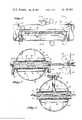
- FIG. 1shows a perspective view of an automated line for continuously preparing a laminate.
- FIG. 2shows an enlarged fragmented perspective view partially in section of the laminate build up as shown in FIG. 1.
- FIG. 3shows a fragmented side elevational view looking toward the inlet of the curing chambers of the automated line shown in FIG. 1.
- FIG. 4shows a fragmented sectional end view taken along line 4--4 of FIG. 3.
- FIG. 5shows another sectional end view taken along line 5--5 of FIG. 3.
- FIG. 6is yet another sectional end view of the curing chambers showing the pre-heating arrangement for the curing chambers.
- FIG. 7shows a fragmented side elevation sectional view of a side of the curing chambers.
- FIG. 8shows a perspective view of the automated line of this invention forming a shaped composite.
- FIG. 9shows a fragmented side elevational view looking toward the inlet to the curing chamber die section of FIG. 8.
- the conveyorized laminating machine 10has a roll unreeling section 12, feed section 14, curing section 16, and a microwave generator 18 to provide energy to the curing section.
- a composite laminate 20 having a non-metallic honeycomb core 22is being formed.
- the honeycomb coreis prepared from any of the reinforced plastics, such as, but not limited to, a nylon fiber treated with a heat resistant phenolic resin sold under the trade name of Nomex.
- the layersin addition to the honeycomb core, include an epoxy adhesive layer 24, and graphite fibers preimpreganted with an epoxy resin in layers 26, 28 and 30. These reinforcing layers may be unidirectional, woven, or multidirectional with the fiber combination at zero, forty-five and ninety degrees.
- a light weight glass scrimis used when the multidirectional fibers are at plus or minus 45 degrees to prevent fiber distortion during the pultrusion.
- the reinforcing materialsare not limited to graphite, but may be any other known reinforcing fibers such as boron or glass, and various resins may be used.
- the resinmay be applied after the fibers are unrolled, however, it is preferable they be preimpregnated with the resin to assist in handling and to closely control the ratio of resin to fiber.
- the preimpregnated reinforcing layeris rolled up with a layer of easily separating material such as a release treated cloth or paper. Each reinforcing layer is handled in the same manner and will be understood by reference to reinforcing layer 26.
- a roll made up of the reinforcing layer 26 and separating layer 32is placed on roller 34 which has its rotation controlled by air actuated slip clutch 36. Alternately a mechanical disc brake may be used.
- the separating layer 32meanwhile is wound around wind up roller 37 which will collect said separating layer as the reinforcing layer is unwound.
- the adhesive layer 24is a resin partially cured in what is commonly called “advanced to the ⁇ B ⁇ stage" to permit flowing sufficient to contact edges of and to be bonded to the honeycomb core without flowing into and filling the cells of the honeycomb.
- This adhesive layercomes on a roll made up of the adhesive layer and separating layer 38 which is placed on a roller 40 which has its rotation controlled by an air actuated slip clutch 42.
- the separating layermeanwhile is wound up on roller 43.
- the adhesive layermay be preapplied to the core by roller coating or it may be dispensed with and a bond obtained between the reinforcing layers and the honeycomb core by use of the resin advanced to the "B" stage in the preimpregnated reinforcing layer.
- the curing section 16as best shown in FIGS. 3 through 7 consists of a microwave applicator or curing chamber 44 through which microwave energy is directed.
- the chamberpreferably of a cylindrical shaped aluminum, is divided into a pair of compartments 46 and 48.
- the compartmentsare bounded on the sides by radially extending disc-shaped walls 50.
- These walls of a material essentially transparent to microwaves, such as quartz or aluminum oxide,are clamped by a pair of flanges 52 and 54; which in turn are secured by bolts 56.
- An O-ring seal 58provides an air tight seal.
- Resilient barrier diaphragms 60 and 62are sealingly adhered at 64 and 66 respectively to the side 68 of the chamber, and to the sidewalls 50 at 70 and 72.
- the resilient materialis essentially transparent to microwaves and was prepared of a silicone rubber.
- a sight tube 76 to permit use of a line of sight infrared radiation pyrometerextends through compartment 46.
- the tubeis adhesively joined to resilient member 60 at 78 and is sealed off with O-ring seal 80 located in collar 82.
- the opening 74 through the chamber and between the two compartments 46 and 48 and sidewalls 50provide a space for dies used to contour layers of material passing through the chamber.
- the diescomprise a pair of platens 84 and 86 used in combination with a pair of shims 88 and 90, all of which are essentially transparent to microwaves.
- the platensare preferably of quartz or aluminum oxide and the shims are of tetrafluoroethylene.
- the upper platenis of a length to extend outside the chamber where a set of four cylinders 92, actuated by a source of compressed air, not shown, will raise the upper platen to provide a means for allowing layers of composite material to be introduced between the platens.
- side spacers 94 and 96may be placed in the opening.
- the side spacersmay be left out as it is not imperative the sides be contained when curing honeycomb cored panels.
- FIG. 6shows a means of preheating to prevent such rejection.
- Strip heaters 98are placed along the wall 68 of the chamber 44, and panel heater 100 is placed between and in contact with the platens. Electrical energy, from a source not shown, flows to the strip heaters along the wall through electrical conductive lines 102 and 104 and to the between platens panel heater through lines 106 and 108.
- Pipe nipples 112, with couplings 114,are joined to and extend through the wall 68 of the chamber 44.
- Air hoses 116connect to the couplings and provide means for directing compressed air through a pressure regulator from a compressed air source, neither of which are shown. It is preferable the hoses be innerconnected as it is desireable to have the same pressure in each compartment.
- Microwave energy from the microwave generator 18flows through waveguide 118, and dividing ducts 120 and 122 thence into the chamber 44.
- the feed beltsare synchronized by drive rolls 126 and kept tight and aligned with idler rolls 128.
- the elongated laminated composite structuremay be cut to length by any known means such as, but not limited to, a water jet cutter 130 illustrated in FIG. 1.
- FIGS. 8 and 9the same curing section 16 with chamber 44 having opening 74 is used to continuously form an angle-shaped composite structure 132.
- a multi-section die of ceramic type materialsuch as quartz or aluminum oxide is used with the die made up of part numbers 134, 136, 138, 140 and 142.
- Layers 26a, 28a and 30a of reinforcing fibers preimpregnated with a resinare placed between feeder belts 124a then through the shaping die in the chamber.
- a pre-shaping forming die 150is used ahead of the chamber to bring the feeder belts with the multilayered layup to the angle shape before it enters the chamber.
- the feeder beltsare turned over at the edges at 144 and 146, as best shown in FIG. 9, to encase the fiber reinforced layers as they move through the chamber. It is not desired to limit the shape of the formed elongated composite structural members to an angle shape as various shapes may be formed by use of the proper die.
- platen 84is raised by cylinders 92, panel heater 100 placed between the platens, and electrical energy turned on to all the heaters until the chamber 44 and the platens 84 and 86 are up to temperature.
- This temperaturewill be selected based on the core and face materials in combination with the resins used, and will be determined with a pyrometer sighting through sight tube 76 onto platen 84.
- the honeycomb core, adhesive and reinforcing layersare placed between the feed belts 124 and under the platens.
- the top platenis lowered, air pressure introduced into compartments 46 and 48, the microwave generator 18 turned on, drive rolls 126 started and slip clutches 36 and 42 adjusted to continuously and automatically produce the elongated composite structural member.
Landscapes
- Engineering & Computer Science (AREA)
- Mechanical Engineering (AREA)
- Physics & Mathematics (AREA)
- Electromagnetism (AREA)
- Chemical & Material Sciences (AREA)
- Composite Materials (AREA)
- Fluid Mechanics (AREA)
- Moulding By Coating Moulds (AREA)
- Laminated Bodies (AREA)
Abstract
Description
The usual methods of preparing a laminated panel structure are slow and expensive. Layers of material are laid up by hand in a mandrel which is then placed in an autoclave for a considerable length of time to effect a cured laminate.
In U.S. Pat. No. 3,056,440 to Mello, plywood was made in a continuous process using a two drum press with each drum of a plurality of pneumatically inflated tires placed coaxially side by side and having laterally extending metal bars on the outer tread that are electrically heated when in contact with the plywood.
U.S. Pat. No. 3,808,968 shows a press for curing conveyor belt ends using a pair of platens with a plurality of U-shaped cross-members joined at the ends and each having a rubber hose in the U-member to apply pressure to the platens. A conveyorized system was discovered that will continuously form an elongated composite laminate.
Rolls of structurally reinforcing material are formed into layers and run through a microwave curing applicator to be continuously formed into a laminate. The layers are fed through the applicator with a pair of slip belts that feed the material while sliding through dies located in the applicator. The dies are pneumatically pressurized to exert pressure while curing the laminate.
FIG. 1 shows a perspective view of an automated line for continuously preparing a laminate.
FIG. 2 shows an enlarged fragmented perspective view partially in section of the laminate build up as shown in FIG. 1.
FIG. 3 shows a fragmented side elevational view looking toward the inlet of the curing chambers of the automated line shown in FIG. 1.
FIG. 4 shows a fragmented sectional end view taken along line 4--4 of FIG. 3.
FIG. 5 shows another sectional end view taken alongline 5--5 of FIG. 3.
FIG. 6 is yet another sectional end view of the curing chambers showing the pre-heating arrangement for the curing chambers.
FIG. 7 shows a fragmented side elevation sectional view of a side of the curing chambers.
FIG. 8 shows a perspective view of the automated line of this invention forming a shaped composite.
FIG. 9 shows a fragmented side elevational view looking toward the inlet to the curing chamber die section of FIG. 8.
The conveyorizedlaminating machine 10 has a rollunreeling section 12,feed section 14, curingsection 16, and a microwave generator 18 to provide energy to the curing section. In FIG. 1 acomposite laminate 20 having anon-metallic honeycomb core 22 is being formed. The honeycomb core is prepared from any of the reinforced plastics, such as, but not limited to, a nylon fiber treated with a heat resistant phenolic resin sold under the trade name of Nomex. The layers, in addition to the honeycomb core, include an epoxyadhesive layer 24, and graphite fibers preimpreganted with an epoxy resin inlayers layer 26. A roll made up of the reinforcinglayer 26 and separatinglayer 32 is placed onroller 34 which has its rotation controlled by air actuatedslip clutch 36. Alternately a mechanical disc brake may be used. The separatinglayer 32 meanwhile is wound around wind up roller 37 which will collect said separating layer as the reinforcing layer is unwound. Theadhesive layer 24 is a resin partially cured in what is commonly called "advanced to the `B` stage" to permit flowing sufficient to contact edges of and to be bonded to the honeycomb core without flowing into and filling the cells of the honeycomb. This adhesive layer comes on a roll made up of the adhesive layer and separatinglayer 38 which is placed on aroller 40 which has its rotation controlled by an air actuatedslip clutch 42. The separating layer meanwhile is wound up onroller 43. Alternatively the adhesive layer may be preapplied to the core by roller coating or it may be dispensed with and a bond obtained between the reinforcing layers and the honeycomb core by use of the resin advanced to the "B" stage in the preimpregnated reinforcing layer.
Thecuring section 16, as best shown in FIGS. 3 through 7 consists of a microwave applicator orcuring chamber 44 through which microwave energy is directed. The chamber, preferably of a cylindrical shaped aluminum, is divided into a pair ofcompartments flanges bolts 56. An O-ring seal 58 provides an air tight seal.Resilient barrier diaphragms side 68 of the chamber, and to the sidewalls 50 at 70 and 72. These two compartments are spaced apart along a plane of the centerline of the chamber to form anopening 74 through the chamber. The resilient material is essentially transparent to microwaves and was prepared of a silicone rubber. Asight tube 76 to permit use of a line of sight infrared radiation pyrometer extends throughcompartment 46. The tube is adhesively joined toresilient member 60 at 78 and is sealed off with O-ring seal 80 located incollar 82.
The opening 74 through the chamber and between the twocompartments platens shims cylinders 92, actuated by a source of compressed air, not shown, will raise the upper platen to provide a means for allowing layers of composite material to be introduced between the platens. Before the composite materials are entered, and while the cylinders are holding the upper platen up,side spacers
To prevent rejection of the first part of a run due to the heat sink effect in the walls of the curing chamber and in the platens, FIG. 6 shows a means of preheating to prevent such rejection.Strip heaters 98 are placed along thewall 68 of thechamber 44, andpanel heater 100 is placed between and in contact with the platens. Electrical energy, from a source not shown, flows to the strip heaters along the wall through electricalconductive lines 102 and 104 and to the between platens panel heater throughlines 106 and 108.
Pipe nipples 112, withcouplings 114, are joined to and extend through thewall 68 of thechamber 44.Air hoses 116 connect to the couplings and provide means for directing compressed air through a pressure regulator from a compressed air source, neither of which are shown. It is preferable the hoses be innerconnected as it is desireable to have the same pressure in each compartment.
Microwave energy from the microwave generator 18 flows throughwaveguide 118, and dividingducts chamber 44.
As pressure is applied to the compartments it is transmitted through the resilient members, and the platens into the layers of starting material or layup as it passes through the chamber to form and cure the layup to become the laminatedcomposite structure 20. The platens remain stationary as the layup passes by. The layup is fed through the chamber bycontinuous belts 124. The belts actually pull the laminate composite through the platens by means of the friction force developed between the belts and the laminate composite when pneumatic pressure is maintained. These belts are of a material essentially transparent to microwaves, have lubricity to act as a slip surface passing by the platens, and act as a parting agent to prevent resin build-up. A fiber reinforced tetrafluoroethylene material was used. The feed belts are synchronized by drive rolls 126 and kept tight and aligned with idler rolls 128. The elongated laminated composite structure may be cut to length by any known means such as, but not limited to, awater jet cutter 130 illustrated in FIG. 1.
In FIGS. 8 and 9 thesame curing section 16 withchamber 44 havingopening 74 is used to continuously form an angle-shapedcomposite structure 132. A multi-section die of ceramic type material such as quartz or aluminum oxide is used with the die made up ofpart numbers Layers feeder belts 124a then through the shaping die in the chamber. A pre-shaping forming die 150 is used ahead of the chamber to bring the feeder belts with the multilayered layup to the angle shape before it enters the chamber. The feeder belts are turned over at the edges at 144 and 146, as best shown in FIG. 9, to encase the fiber reinforced layers as they move through the chamber. It is not desired to limit the shape of the formed elongated composite structural members to an angle shape as various shapes may be formed by use of the proper die.
To fabricate an elongated composite laminate, as shown in FIGS. 1 through 7,platen 84 is raised bycylinders 92,panel heater 100 placed between the platens, and electrical energy turned on to all the heaters until thechamber 44 and theplatens sight tube 76 ontoplaten 84. The honeycomb core, adhesive and reinforcing layers are placed between thefeed belts 124 and under the platens. The top platen is lowered, air pressure introduced intocompartments clutches
Claims (35)
1. An apparatus for forming an elongated laminated structural member from a plurality of rolls of starting materials some of which contain uncured adhesive resins, the apparatus comprising: means for layering up material from rolls of starting material, slip means for feeding the layered material through a pressurized die in an energized microwave applicator chamber to cure an adhesive resin in the layered material to form an elongated laminated structural member, and pneumatic means for applying pressure through the die to the layered material while the slip means feeding the layered material slides through the die in the chamber to control the dimensions of the laminate during the curing.
2. An apparatus for forming an elongated composite structure comprising: means for applying adjustable tension to resist unrolling of each of a plurality of aligned rolls of forming material, means for feeding the forming material in a multilayer form through a microwave applicator chamber, stationary die means within the applicator chamber for controlling contours of the multilayer as it passes through the chamber, means for energizing the chamber to cure adhesive resins included in the multilayer forming material to set up the adhesive and form an elongated composite structure emerging from the chamber, and the means for feeding the forming material through the chamber includes means for slipping through the stationary die means for controlling the contours of the multilayer.
3. An apparatus for forming an elongated composite structure as in claim 2 further comprising pneumatic means for exerting pressure on the stationary die means for controlling contours.
4. An apparatus for forming an elongated composite structure as in claim 2 wherein the stationary die means for controlling contours are platens for imparting sandwich shape to the composite structure.
5. An apparatus for forming an elongated composite structure as in claim 2 wherein the stationary die means for controlling contours impart varied shapes to the composite structure, and forming means for pre-shaping the multilayered material to match the die are located ahead of the stationary die means.
6. An apparatus for forming an elongated composite structure as in claim 3 wherein the stationary die means for controlling contours are platens for imparting sandwich shape to the composite structure.
7. An apparatus for forming an elongated composite structure as in claim 3 wherein the stationary die means for controlling contours include die means for imparting varied shapes to the composite structure, and forming means ahead of the die means for pre-shaping the multilayered material as it moves to the die means.
8. A process for conveyorized formation of an elongated composite structure, the steps comprising: extending dies that are transparent to microwaves through a microwave curing chamber, selecting feed belts that have lubricity and are transparent to microwaves, passing the feed belts through the dies, aligning a plurality of rolls of reinforcing materials at least some of which are preimpregnated with a thermosetting resin, placing the reinforcing materials in layered form between the feed belts, energizing to obtain microwaves in the curing chamber, applying pressure to the dies, and driving the feed belts to form and cure the reinforcing materials into an elongated composite structure as it emerges from the chamber.
9. A process for formation of an elongated composite structure as in claim 8, further steps comprising: applying controlled resistance to unrolling to the reinforcing materials.
10. A process for formation of an elongated composite structure as in claim 8, further comprises selecting pneumatics as the means for applying pressure to the dies.
11. A process for conveyorized formation of an elongated composite structure, the steps comprising: extending dies that are transparent to microwaves through a microwave curing chamber, forming the microwave curing chamber by placing members transparent to microwave as sides of the chamber, sealing it off top and bottom with a resilient material that is also transparent to microwaves, selecting feed belts that have lubricity and are transparent to microwaves, passing the feed belts through the dies, aligning a plurality of rolls of reinforcing materials at least some of which are preimpregnated with a thermosetting resin, placing the reinforcing materials in layered form between the feed belts, energizing to obtain microwaves in the curing chamber, introducing a gas into compartments formed behind the resilient material in the curing chamber to exert pressure on the dies, and driving the feed belts to form and cure the reinforcing materials into an elongated composite structure as it emerges from the chamber.
12. A process for formation of an elongated composite structure as in claim 11 further comprising sealingly installing a sight tube through a wall of one of the compartments and the resilient material for taking pyrometer readings on the surface of the die.
13. A process for formation of an elongated composite structure as in claim 11 further steps comprising selecting a non-metallic honeycomb as one of the rolls of reinforcing material, and locating the honeycomb within the layer of reinforcing materials to become a core of the elongated composite structure.
14. A process for formation of an elongated composite structure as in claim 12 further steps comprising selecting a non-metallic honeycomb as one of the rolls of reinforcing material, and locating the honeycomb within the layer of reinforcing material to become a core of the elongated composite structure.
15. A process for formation of an elongated composite structure as in claim 11, steps further comprising placing pre-shaping forms ahead of the dies to shape the layered reinforcing material before it enters the dies.
16. An apparatus for forming an elongated laminate from layers of non-metallic resin impregnated structural members as the members pass through an apparatus comprising: a microwave applicator chamber, means for compartmentalizing a section of the chamber into two sealed compartments having an opening extending between the compartments and through the chamber, means die within the opening layers of non-metallic structural members as they pass through the opening, means for applying pneumatic pressure from at least one of the compartments against the die means and means for introducing microwaves into the chamber.
17. An apparatus as in claim 16 further comprising means for pyrometric viewing of temperatures of the shaping means within the opening.
18. An apparatus for forming an elongated laminate from layers of non-metallic structural members, some of which are impregnated with a resin, as the members pass through the apparatus which comprises: a microwave curing chamber; a pair of sealed compartments within the chamber separated by a laterally extending opening, said compartments each having a resilient member contiguous to the opening; a pair of non-metallic platens between which layers of non-metallic resin containing structural members pass, and said platens extend through the opening; means for introducing air into the compartments for exerting pressure on the platens and thence the layered materials; and means for introducing microwaves into the chamber to cure the resin in the layered member to form a composite structural laminate as the member emerges from the microwave curing chamber.
19. An apparatus as in claim 18 further comprising a sight tube to sealingly extend through a wall and through the resilient member of one of the compartments to permit measuring temperature of the platen.
20. An apparatus as in claim 18 further comprising means for raising one of the platens to permit introducing the layered structural material.
21. An apparatus as in claim 18 further comprising a removable metal platen to be located between the non-metallic platens, and means for heating the metal platen to preheat the non-metallic platens.
22. An apparatus as in claim 18 further comprising a spacer to be located between each platen and its contiguous compartment.
23. An apparatus for forming an elongated laminate from layers of non-metallic structural members, some of which are impregnated with a resin, as the members pass through an apparatus which comprises: a microwave curing chamber having an opening through its sides, a pair of spaced apart laterally extending walls sealed to the chamber and selected from a material essentially transparent to microwaves, a pair of spaced apart longitudinally extending resilient members selected from a material essentially transparent to microwaves and the resilient members sealingly joined to the walls and the sides of the chamber to form a pair of spaced apart compartments separated by the opening, a die to extend through the opening and selected from a material essentially transparent to microwaves, means for generating microwaves in the chamber to cure resin in a resin impregnated nonmetallic structurally reinforced member passing through the dies, and means for pneumatically pressurizing the compartments to exert pressure on the die and thence pressure on the member as it is being cured in the die.
24. An apparatus as in claim 23 further comprising a tube selected from a material essentially transparent to microwaves, said tube to sealingly extend through one of the compartments and open end at the die to permit access for measuring the temperature of the die.
25. An apparatus as in claim 23 wherein the die comprises a pair of platens.
26. An apparatus as in claim 25 further comprising automatic means for raising one of the platens.
27. An apparatus as in claim 25 further comprising a spacer selected from a material essentially transparent to microwaves to be placed between each platen and the contiguous compartment.
28. An apparatus as in claim 26 further comprising means for preheating the platens.
29. An apparatus as in claim 24 wherein the die comprises a pair of platens.
30. An apparatus as in claim 29 further comprising automatic means for raising one of the platens.
31. An apparatus as in claim 29 further comprising a spacer selected from a material essentially transparent to microwaves to be placed between each platen and the contiguous compartment.
32. An apparatus as in claim 30 further comprising means for preheating the platens.
33. A method of continuously pressurizing and curing a layup of layered resin impregnated structural materials to form the layup into an elongated laminated composite structure, the steps comprising: passing layered resin impregnated structural material laterally through an opening in a microwave curing chamber, controlling contour of the layered material by restraining with a die that extends through the opening, pressurizing the die with pneumatic pressure acting through a contiguous elastic side of a pair of compartments located within the curing chamber, and introducing microwaves into the chamber.
34. A method as in claim 33, further steps comprising: locating a sight tube sealingly extending through one of the compartments and opening at the die, and monitoring temperature of the die with a pyrometer.
35. A method as in claim 33, further steps comprising: selecting a pair of platens as the die, and including a core of honeycomb among the layers of structural materials.
Priority Applications (1)
| Application Number | Priority Date | Filing Date | Title |
|---|---|---|---|
| US05/865,089US4186044A (en) | 1977-12-27 | 1977-12-27 | Apparatus and method for forming laminated composite structures |
Applications Claiming Priority (1)
| Application Number | Priority Date | Filing Date | Title |
|---|---|---|---|
| US05/865,089US4186044A (en) | 1977-12-27 | 1977-12-27 | Apparatus and method for forming laminated composite structures |
Publications (1)
| Publication Number | Publication Date |
|---|---|
| US4186044Atrue US4186044A (en) | 1980-01-29 |
Family
ID=25344686
Family Applications (1)
| Application Number | Title | Priority Date | Filing Date |
|---|---|---|---|
| US05/865,089Expired - LifetimeUS4186044A (en) | 1977-12-27 | 1977-12-27 | Apparatus and method for forming laminated composite structures |
Country Status (1)
| Country | Link |
|---|---|
| US (1) | US4186044A (en) |
Cited By (44)
| Publication number | Priority date | Publication date | Assignee | Title |
|---|---|---|---|---|
| US4477707A (en)* | 1982-11-24 | 1984-10-16 | General Electric Company | Electromagnetic field heating apparatus for curing resin/fiber composites in continuous pultrusion processes |
| EP0103396A3 (en)* | 1982-08-10 | 1985-05-08 | Macmillan Bloedel Limited | Microwave applicator for continuous press |
| FR2584258A1 (en)* | 1985-06-28 | 1987-01-02 | Elf Aquitaine | METHOD AND DEVICE FOR THERMALLY TREATING A CONDUCTIVE ELEMENT AT LEAST PARTIALLY CONSISTING OF A CONDUCTIVE MATERIAL |
| US4637199A (en)* | 1985-01-30 | 1987-01-20 | International Paper Company | Induction sealing of paperboard |
| FR2585283A1 (en)* | 1985-07-25 | 1987-01-30 | Planet Wattohm Cie | Process and machine for the manufacture of a meshed element made from synthetic material reinforced with fibre(s), especially for a cableway |
| US4687343A (en)* | 1983-09-09 | 1987-08-18 | Theta Industries, Inc. | Deformation dilatometer platens |
| US4883552A (en)* | 1986-12-05 | 1989-11-28 | Phillips Petroleum Company | Pultrusion process and apparatus |
| USRE33467E (en)* | 1985-01-30 | 1990-12-04 | International Paper Company | Induction sealing of paperboard |
| JPH032228A (en)* | 1989-03-31 | 1991-01-08 | General Electric Co <Ge> | Process for producting product from impregnated glass fiber obtained by impregnating glass fiber with thermoplastic resin |
| US5139710A (en)* | 1991-05-24 | 1992-08-18 | Global Thermal Conditioning, Inc. | Shadow boundary process for the continuous radiant cure of composites |
| US5139843A (en)* | 1988-11-24 | 1992-08-18 | Tonen Kabushiki Kaisha | Elongated lightweight fiber reinforced composite resin pultrusion-formed piece |
| US5183600A (en)* | 1991-07-19 | 1993-02-02 | Nevamar Corporation | Method and apparatus for continuous casting of polymerizable material |
| FR2683420A1 (en)* | 1991-11-05 | 1993-05-07 | Bordeaux 1 Universite | DEVICE FOR THE APPLICATION OF MICROWAVE FOR THE TREATMENT OF A MATERIAL. |
| US5260006A (en)* | 1990-01-23 | 1993-11-09 | Nevamar Corporation | Method and apparatus for continuous casting of polymerizable thermosetting material |
| US5283099A (en)* | 1991-09-24 | 1994-02-01 | Dynamic Technologies, Inc. | Enhanced structural core material |
| WO1994002306A1 (en)* | 1992-07-21 | 1994-02-03 | Akzo Nobel N.V. | A method of manufacturing a ud-reinforced pwb laminate |
| US5328744A (en)* | 1990-10-09 | 1994-07-12 | E. I. Du Pont De Nemours And Company | Panel having a core with thermoplastic resin facings |
| US5527598A (en)* | 1993-05-05 | 1996-06-18 | Albany International Research Co. | Composite sandwich element |
| US5536921A (en)* | 1994-02-15 | 1996-07-16 | International Business Machines Corporation | System for applying microware energy in processing sheet like materials |
| US5705022A (en)* | 1995-06-08 | 1998-01-06 | International Business Machines Corporation | Continuous lamination of electronic structures |
| US5756975A (en)* | 1996-11-21 | 1998-05-26 | Ewes Enterprises | Apparatus and method for microwave curing of resins in engineered wood products |
| US6242726B1 (en)* | 1996-11-21 | 2001-06-05 | George M. Harris | Adjustable microwave field stop |
| US20030155351A1 (en)* | 2002-02-18 | 2003-08-21 | Raute Oyj | Apparatus for hot-pressing a planar product |
| US20030207083A1 (en)* | 1999-12-23 | 2003-11-06 | Krister Hansson | Process for the manufacturing of surface elements |
| US20050109445A1 (en)* | 2003-11-25 | 2005-05-26 | Pergo (Europe) Ab | Process for achieving a surface structure on a decorative laminate |
| US20070283660A1 (en)* | 2006-06-07 | 2007-12-13 | James Michael Blahut | Composite assembly with saturated bonding mass and process of reinforced attachment |
| US20080023130A1 (en)* | 2006-07-31 | 2008-01-31 | Airbus Espana, S.L. | Tool and process for manufacturing pieces of composite materials outside an autoclave |
| EP2065186A1 (en) | 2007-11-30 | 2009-06-03 | Homag Holzbearbeitungssysteme AG | Method for manufacturing a lightweight construction sheet and device for executing the method |
| WO2009130060A1 (en)* | 2008-04-25 | 2009-10-29 | Fritz Egger Gmbh & Co. | Method for the production of a lightweight building panel for furniture construction |
| ITPN20080093A1 (en)* | 2008-12-23 | 2010-06-24 | Nardi Mirco De | MATERIAL COUPLED, PROCEDURE AND PLANT |
| CN101918188A (en)* | 2007-12-14 | 2010-12-15 | 空客运营有限公司 | Jig and out-of-autoclave process for manufacturing composite material structures |
| RU2420405C2 (en)* | 2006-07-31 | 2011-06-10 | Айрбус Эспанья, С.Л. | Tool and method of producing parts from composite materials outside autoclave (versions) |
| EP2527144A1 (en)* | 2011-05-25 | 2012-11-28 | Wemhöner Surface Technologies GmbH & Co. KG | Method and device for hot pressing component stacks fitted with adhesive for producing sandwich lightweight boards with integrated wood frame core |
| WO2014118523A1 (en)* | 2013-01-30 | 2014-08-07 | Rtl Materials Ltd | Apparatus and method for manufacturing a composite product from plural components |
| EP3037248A1 (en)* | 2014-12-22 | 2016-06-29 | Magna Steyr Fahrzeugtechnik AG & Co KG | Method and device for producing a sandwich component |
| CZ307401B6 (en)* | 2017-05-17 | 2018-07-25 | ASPARA s.r.o. | A method of continuous production of laminated blocks from thin flexible materials and a device for implementing this method |
| US20190047184A1 (en)* | 2016-02-09 | 2019-02-14 | Leonhardt, Andrä Und Partner Beratende Ingenieure Vbi Ag | Method for producing anchor rods from a fiber composite material, and anchor rod |
| EP3480008A1 (en)* | 2017-11-03 | 2019-05-08 | Bucher Leichtbau AG | Lightweight component |
| EP3616889A1 (en)* | 2018-08-27 | 2020-03-04 | The Boeing Company | Forming contoured elongate composite structures |
| RU2717523C2 (en)* | 2015-05-18 | 2020-03-23 | Зе Боинг Компани | Cylinder system for hardening of composite parts |
| CN111196062A (en)* | 2018-11-20 | 2020-05-26 | 波音公司 | Composite laminated structure with porous core formed by continuous compression molding |
| CN111976038A (en)* | 2020-06-30 | 2020-11-24 | 湖北平安电工股份有限公司 | Hot die pressing production method of mica special-shaped piece |
| WO2021010980A1 (en)* | 2019-07-16 | 2021-01-21 | General Electric Company | System and method for manufacturing panels for use in wind turbine rotor blade components |
| US20220126528A1 (en)* | 2019-02-14 | 2022-04-28 | Rolls-Royce Plc | A method of manufacturing a composite blade |
Citations (7)
| Publication number | Priority date | Publication date | Assignee | Title |
|---|---|---|---|---|
| US2871911A (en)* | 1953-01-13 | 1959-02-03 | Glastrusions | Apparatus for producing elongated articles from fiber-reinforced plastic material |
| US3567544A (en)* | 1967-12-22 | 1971-03-02 | Standard Brands Chem Ind Inc | Method of hot melt seaming of fabric materials using a high frequency electric field |
| US3597567A (en)* | 1969-09-24 | 1971-08-03 | Ray M Johnson | Microwave applicator for heating continuous web |
| US3765985A (en)* | 1970-11-06 | 1973-10-16 | Raffinage Cie Francaise | Apparatus for welding two sheets by ultra high frequency energy |
| US3769127A (en)* | 1968-04-23 | 1973-10-30 | Goldsworthy Eng Inc | Method and apparatus for producing filament reinforced tubular products on a continuous basis |
| US3793108A (en)* | 1967-06-23 | 1974-02-19 | Glastrusions | Augmented curing of reinforced plastic stock |
| US4012267A (en)* | 1975-07-10 | 1977-03-15 | Bell Telephone Laboratories, Incorporated | Process for producing pultruded clad composites |
- 1977
- 1977-12-27USUS05/865,089patent/US4186044A/ennot_activeExpired - Lifetime
Patent Citations (7)
| Publication number | Priority date | Publication date | Assignee | Title |
|---|---|---|---|---|
| US2871911A (en)* | 1953-01-13 | 1959-02-03 | Glastrusions | Apparatus for producing elongated articles from fiber-reinforced plastic material |
| US3793108A (en)* | 1967-06-23 | 1974-02-19 | Glastrusions | Augmented curing of reinforced plastic stock |
| US3567544A (en)* | 1967-12-22 | 1971-03-02 | Standard Brands Chem Ind Inc | Method of hot melt seaming of fabric materials using a high frequency electric field |
| US3769127A (en)* | 1968-04-23 | 1973-10-30 | Goldsworthy Eng Inc | Method and apparatus for producing filament reinforced tubular products on a continuous basis |
| US3597567A (en)* | 1969-09-24 | 1971-08-03 | Ray M Johnson | Microwave applicator for heating continuous web |
| US3765985A (en)* | 1970-11-06 | 1973-10-16 | Raffinage Cie Francaise | Apparatus for welding two sheets by ultra high frequency energy |
| US4012267A (en)* | 1975-07-10 | 1977-03-15 | Bell Telephone Laboratories, Incorporated | Process for producing pultruded clad composites |
Cited By (87)
| Publication number | Priority date | Publication date | Assignee | Title |
|---|---|---|---|---|
| EP0103396A3 (en)* | 1982-08-10 | 1985-05-08 | Macmillan Bloedel Limited | Microwave applicator for continuous press |
| US4477707A (en)* | 1982-11-24 | 1984-10-16 | General Electric Company | Electromagnetic field heating apparatus for curing resin/fiber composites in continuous pultrusion processes |
| US4687343A (en)* | 1983-09-09 | 1987-08-18 | Theta Industries, Inc. | Deformation dilatometer platens |
| US4637199A (en)* | 1985-01-30 | 1987-01-20 | International Paper Company | Induction sealing of paperboard |
| USRE33467E (en)* | 1985-01-30 | 1990-12-04 | International Paper Company | Induction sealing of paperboard |
| FR2584258A1 (en)* | 1985-06-28 | 1987-01-02 | Elf Aquitaine | METHOD AND DEVICE FOR THERMALLY TREATING A CONDUCTIVE ELEMENT AT LEAST PARTIALLY CONSISTING OF A CONDUCTIVE MATERIAL |
| WO1987000387A1 (en)* | 1985-06-28 | 1987-01-15 | Societe Nationale Elf Aquitaine | Method and device for the thermal treatment of a conductor element |
| US4780585A (en)* | 1985-06-28 | 1988-10-25 | Societe Nationale Elf Aquitaine | Method and device for the thermal treatment of a conductor element at least partially constituted by a conducting material |
| FR2585283A1 (en)* | 1985-07-25 | 1987-01-30 | Planet Wattohm Cie | Process and machine for the manufacture of a meshed element made from synthetic material reinforced with fibre(s), especially for a cableway |
| US4883552A (en)* | 1986-12-05 | 1989-11-28 | Phillips Petroleum Company | Pultrusion process and apparatus |
| US5139843A (en)* | 1988-11-24 | 1992-08-18 | Tonen Kabushiki Kaisha | Elongated lightweight fiber reinforced composite resin pultrusion-formed piece |
| JPH032228A (en)* | 1989-03-31 | 1991-01-08 | General Electric Co <Ge> | Process for producting product from impregnated glass fiber obtained by impregnating glass fiber with thermoplastic resin |
| EP0389798A3 (en)* | 1989-03-31 | 1992-01-02 | General Electric Company | Process for impregnation of glass fiber reinforcement with thermoplastic resins and for producing articles from the impregnated glass fiber |
| US5194190A (en)* | 1989-03-31 | 1993-03-16 | General Electric Company | Process for impregantion of glass fiber reinforcement with thermoplastic resins |
| JPH069877B2 (en) | 1989-03-31 | 1994-02-09 | ゼネラル・エレクトリック・カンパニイ | Method for producing resin-impregnated glass fiber composite product |
| US5260006A (en)* | 1990-01-23 | 1993-11-09 | Nevamar Corporation | Method and apparatus for continuous casting of polymerizable thermosetting material |
| US5328744A (en)* | 1990-10-09 | 1994-07-12 | E. I. Du Pont De Nemours And Company | Panel having a core with thermoplastic resin facings |
| US5139710A (en)* | 1991-05-24 | 1992-08-18 | Global Thermal Conditioning, Inc. | Shadow boundary process for the continuous radiant cure of composites |
| US5183600A (en)* | 1991-07-19 | 1993-02-02 | Nevamar Corporation | Method and apparatus for continuous casting of polymerizable material |
| US5283099A (en)* | 1991-09-24 | 1994-02-01 | Dynamic Technologies, Inc. | Enhanced structural core material |
| FR2683420A1 (en)* | 1991-11-05 | 1993-05-07 | Bordeaux 1 Universite | DEVICE FOR THE APPLICATION OF MICROWAVE FOR THE TREATMENT OF A MATERIAL. |
| AU677957B2 (en)* | 1992-07-21 | 1997-05-15 | Amp-Akzo Linlam Vof | A method of manufacturing a UD-reinforced PWB laminate |
| US5662761A (en)* | 1992-07-21 | 1997-09-02 | Amp-Akzo Lin Lam Vof | Method of manufacturing a UD-reinforced PWB laminate |
| WO1994002306A1 (en)* | 1992-07-21 | 1994-02-03 | Akzo Nobel N.V. | A method of manufacturing a ud-reinforced pwb laminate |
| CN1048446C (en)* | 1992-07-21 | 2000-01-19 | 阿木普-阿克佐迭片公司 | Process for the manufacture of composite laminates containing unidirectional reinforcing fibers for use as printed circuit boards |
| US5527598A (en)* | 1993-05-05 | 1996-06-18 | Albany International Research Co. | Composite sandwich element |
| US5536921A (en)* | 1994-02-15 | 1996-07-16 | International Business Machines Corporation | System for applying microware energy in processing sheet like materials |
| US5779844A (en)* | 1995-06-08 | 1998-07-14 | International Business Machines Corporation | Continuous lamination of electronic structures |
| US5705022A (en)* | 1995-06-08 | 1998-01-06 | International Business Machines Corporation | Continuous lamination of electronic structures |
| US5756975A (en)* | 1996-11-21 | 1998-05-26 | Ewes Enterprises | Apparatus and method for microwave curing of resins in engineered wood products |
| US5892208A (en)* | 1996-11-21 | 1999-04-06 | Ewes Enterprises | Apparatus and method for microwave curing of resins in engineered wood products |
| WO1998023132A1 (en)* | 1996-11-21 | 1998-05-28 | Ewes Enterprises, L.L.C. | Apparatus and method for microwave curing of resins in engineered wood products |
| US6242726B1 (en)* | 1996-11-21 | 2001-06-05 | George M. Harris | Adjustable microwave field stop |
| EP0940060A4 (en)* | 1996-11-21 | 2004-11-24 | Ewes Entpr L L C | Apparatus and method for microwave curing of resins in engineered wood products |
| US9656476B2 (en) | 1999-12-23 | 2017-05-23 | Pergo (Europe) Ab | Process for the manufacturing of surface elements |
| US9636923B2 (en) | 1999-12-23 | 2017-05-02 | Pergo (Europe) Ab | Process for the manufacturing of surface elements |
| US20030207083A1 (en)* | 1999-12-23 | 2003-11-06 | Krister Hansson | Process for the manufacturing of surface elements |
| US6888147B1 (en)* | 1999-12-23 | 2005-05-03 | Pergo (Europe) Ab | Process for the manufacturing of surface elements with a structured top surface |
| US8944543B2 (en) | 1999-12-23 | 2015-02-03 | Pergo (Europe) Ab | Process for the manufacturing of surface elements |
| US20050281993A1 (en)* | 1999-12-23 | 2005-12-22 | Pergo (Europe) Ab | Process for the manufacturing of surface elements with a structured top surface |
| US8950138B2 (en) | 1999-12-23 | 2015-02-10 | Pergo (Europe) Ab | Process for the manufacturing of surface elements |
| US10464339B2 (en) | 1999-12-23 | 2019-11-05 | Pergo (Europe) Ab | Process for the manufacturing of surface elements |
| US9321299B2 (en) | 1999-12-23 | 2016-04-26 | Pergo (Europe) Ab | Process for the manufacturing of surface elements |
| US8741421B2 (en) | 1999-12-23 | 2014-06-03 | Pergo (Europe) Ab | Process for the manufacturing of surface elements with a structured top surface |
| US9636922B2 (en) | 1999-12-23 | 2017-05-02 | Pergo (Europe) Ab | Process for the manufacturing of surface elements |
| US9409412B2 (en) | 1999-12-23 | 2016-08-09 | Pergo (Europe) Ab | Process for the manufacturing of surface elements |
| US20030155351A1 (en)* | 2002-02-18 | 2003-08-21 | Raute Oyj | Apparatus for hot-pressing a planar product |
| US6744025B2 (en)* | 2002-02-18 | 2004-06-01 | Raute Oyj | Apparatus for hot-pressing a planar product |
| US20050109445A1 (en)* | 2003-11-25 | 2005-05-26 | Pergo (Europe) Ab | Process for achieving a surface structure on a decorative laminate |
| US8011165B2 (en)* | 2006-06-07 | 2011-09-06 | Integritect Consulting, Inc. | Composite assembly with saturated bonding mass and process of reinforced attachment |
| US20070283660A1 (en)* | 2006-06-07 | 2007-12-13 | James Michael Blahut | Composite assembly with saturated bonding mass and process of reinforced attachment |
| RU2420405C2 (en)* | 2006-07-31 | 2011-06-10 | Айрбус Эспанья, С.Л. | Tool and method of producing parts from composite materials outside autoclave (versions) |
| WO2008015301A1 (en)* | 2006-07-31 | 2008-02-07 | Airbus España, S.L. | Tool and method for producing pieces of compound materials outside an autoclave |
| US20080023130A1 (en)* | 2006-07-31 | 2008-01-31 | Airbus Espana, S.L. | Tool and process for manufacturing pieces of composite materials outside an autoclave |
| EP2065186B1 (en)* | 2007-11-30 | 2012-03-28 | Homag Holzbearbeitungssysteme AG | Method for manufacturing a lightweight construction sheet |
| EP2065186A1 (en) | 2007-11-30 | 2009-06-03 | Homag Holzbearbeitungssysteme AG | Method for manufacturing a lightweight construction sheet and device for executing the method |
| CN101918188A (en)* | 2007-12-14 | 2010-12-15 | 空客运营有限公司 | Jig and out-of-autoclave process for manufacturing composite material structures |
| DE102008020976B4 (en)* | 2008-04-25 | 2017-02-16 | Fritz Egger Gmbh & Co. Og | Method for producing a lightweight board for furniture construction |
| WO2009130060A1 (en)* | 2008-04-25 | 2009-10-29 | Fritz Egger Gmbh & Co. | Method for the production of a lightweight building panel for furniture construction |
| ITPN20080093A1 (en)* | 2008-12-23 | 2010-06-24 | Nardi Mirco De | MATERIAL COUPLED, PROCEDURE AND PLANT |
| EP2527144A1 (en)* | 2011-05-25 | 2012-11-28 | Wemhöner Surface Technologies GmbH & Co. KG | Method and device for hot pressing component stacks fitted with adhesive for producing sandwich lightweight boards with integrated wood frame core |
| WO2014118523A1 (en)* | 2013-01-30 | 2014-08-07 | Rtl Materials Ltd | Apparatus and method for manufacturing a composite product from plural components |
| US10124545B2 (en) | 2013-01-30 | 2018-11-13 | Rtl Materials Ltd. | Apparatus and method for manufacturing a composite product from plural components |
| CN105073394A (en)* | 2013-01-30 | 2015-11-18 | Rtl原材料有限公司 | Apparatus and method for manufacturing a composite product from plural components |
| GB2510340B (en)* | 2013-01-30 | 2017-12-06 | Rtl Mat Ltd | Apparatus and method for manufacturing a composite product from plural components |
| EP3037248A1 (en)* | 2014-12-22 | 2016-06-29 | Magna Steyr Fahrzeugtechnik AG & Co KG | Method and device for producing a sandwich component |
| RU2675522C1 (en)* | 2014-12-22 | 2018-12-19 | Магна Штайр Фарцойгтехник Аг Унд Ко Кг | Multilayered part manufacturing method and device |
| WO2016102457A3 (en)* | 2014-12-22 | 2016-09-09 | Magna Steyr Fahrzeugtechnik Ag & Co Kg | Method and apparatus for manufacturing a sandwich component |
| US10807350B2 (en) | 2014-12-22 | 2020-10-20 | Magna Steyr Fahrzeugtechnik Ag & Co Kg | Method and apparatus for manufacturing a sandwich part |
| US10308003B2 (en) | 2014-12-22 | 2019-06-04 | Magna Steyr Fahrzeugtechnik Ag & Co Kg | Method and apparatus for manufacturing a sandwich part |
| US11370150B2 (en) | 2015-05-18 | 2022-06-28 | The Boeing Company | Bladder system for curing composite parts |
| RU2717523C2 (en)* | 2015-05-18 | 2020-03-23 | Зе Боинг Компани | Cylinder system for hardening of composite parts |
| US20190047184A1 (en)* | 2016-02-09 | 2019-02-14 | Leonhardt, Andrä Und Partner Beratende Ingenieure Vbi Ag | Method for producing anchor rods from a fiber composite material, and anchor rod |
| US10596767B2 (en)* | 2016-02-09 | 2020-03-24 | Leonhardt, Andrä Und Partner Beratende Ingenieure Vbi Ag | Method for producing anchor rods from a fiber composite material, and anchor rod |
| CZ307401B6 (en)* | 2017-05-17 | 2018-07-25 | ASPARA s.r.o. | A method of continuous production of laminated blocks from thin flexible materials and a device for implementing this method |
| EP3480008A1 (en)* | 2017-11-03 | 2019-05-08 | Bucher Leichtbau AG | Lightweight component |
| EP3616889A1 (en)* | 2018-08-27 | 2020-03-04 | The Boeing Company | Forming contoured elongate composite structures |
| CN110861321B (en)* | 2018-08-27 | 2023-04-28 | 波音公司 | Shaping of shaped elongated composite structures |
| CN110861321A (en)* | 2018-08-27 | 2020-03-06 | 波音公司 | Forming elongated composite structures |
| US10960631B2 (en)* | 2018-08-27 | 2021-03-30 | The Boeing Company | Forming contoured elongate composite structures |
| CN111196062A (en)* | 2018-11-20 | 2020-05-26 | 波音公司 | Composite laminated structure with porous core formed by continuous compression molding |
| US11104085B2 (en)* | 2018-11-20 | 2021-08-31 | The Boeing Company | Composite laminate structure having a cellular core formed using a continuous compression molding process |
| US20220126528A1 (en)* | 2019-02-14 | 2022-04-28 | Rolls-Royce Plc | A method of manufacturing a composite blade |
| WO2021010980A1 (en)* | 2019-07-16 | 2021-01-21 | General Electric Company | System and method for manufacturing panels for use in wind turbine rotor blade components |
| CN114072263A (en)* | 2019-07-16 | 2022-02-18 | 通用电气公司 | System and method for manufacturing panels for use in wind turbine rotor blade components |
| US12377617B2 (en) | 2019-07-16 | 2025-08-05 | Ge Vernova Infrastructure Technology Llc | System and method for manufacturing panels for use in wind turbine rotor blade components |
| CN111976038A (en)* | 2020-06-30 | 2020-11-24 | 湖北平安电工股份有限公司 | Hot die pressing production method of mica special-shaped piece |
Similar Documents
| Publication | Publication Date | Title |
|---|---|---|
| US4186044A (en) | Apparatus and method for forming laminated composite structures | |
| US4420359A (en) | Apparatus for producing fiber-reinforced plastic sheet structures | |
| US6592795B2 (en) | Continuous forming method and device for H-shaped FRP member | |
| US4498941A (en) | Method for producing fiber reinforced sheet structures | |
| US4402778A (en) | Method for producing fiber-reinforced plastic sheet structures | |
| US4633632A (en) | Structural component having a curved wall and apparatus for making such structural component | |
| US6601627B2 (en) | Continuous forming device of fiber reinforced plastic square pipe | |
| ES2643475T3 (en) | Automated resin and fiber deposition for resin infusion | |
| US5228944A (en) | Apparatus for producing composite bodies from layers of plastic flim laminated to one another | |
| EP2035213B1 (en) | Method and apparatus for producing off-axis composite prepreg material | |
| JP2008213311A (en) | Method for continuously forming composite material having stepwise cross-sectional thickness | |
| US10766212B2 (en) | Method and apparatus for forming radius filler kits | |
| JPH10510224A (en) | Wooden tube | |
| EP1418046B1 (en) | Composite sheet material | |
| US8419886B2 (en) | Method of manufacturing composite parts | |
| US4495021A (en) | Apparatus for producing fiber reinforced plastic sheet structures | |
| US20100116421A1 (en) | Method for continuously forming composite material shape member having varied cross-sectional shape | |
| US10821651B2 (en) | Method and apparatus for continuously fabricating a composite sandwich structure | |
| US6910996B1 (en) | Method for producing a honeycomb structure and apparatus therefor | |
| US4379013A (en) | Fine film pressure bags forming composite structures | |
| US3879254A (en) | Fabrication apparatus for butt joining foam plastic billets | |
| US7204286B2 (en) | Apparatus for continuously forming FRP square pipe | |
| DK162151B (en) | PROCEDURE AND PLANT FOR THE MANUFACTURING OF FIBER Reinforced Hollow Plate Profiles | |
| US3784659A (en) | Method of producing continuous plastic shapes | |
| US20200247014A1 (en) | Method and apparatus for impregnating reinforcement material |