US4183619A - Connector pin assembly and method for terminating an optical fiber - Google Patents
Connector pin assembly and method for terminating an optical fiberDownload PDFInfo
- Publication number
- US4183619A US4183619AUS05/806,953US80695377AUS4183619AUS 4183619 AUS4183619 AUS 4183619AUS 80695377 AUS80695377 AUS 80695377AUS 4183619 AUS4183619 AUS 4183619A
- Authority
- US
- United States
- Prior art keywords
- optical fiber
- pin
- opening
- pin members
- forward end
- Prior art date
- Legal status (The legal status is an assumption and is not a legal conclusion. Google has not performed a legal analysis and makes no representation as to the accuracy of the status listed.)
- Expired - Lifetime
Links
Images


Classifications
- G—PHYSICS
- G02—OPTICS
- G02B—OPTICAL ELEMENTS, SYSTEMS OR APPARATUS
- G02B6/00—Light guides; Structural details of arrangements comprising light guides and other optical elements, e.g. couplings
- G02B6/24—Coupling light guides
- G02B6/36—Mechanical coupling means
- G02B6/38—Mechanical coupling means having fibre to fibre mating means
- G02B6/3807—Dismountable connectors, i.e. comprising plugs
- G02B6/3873—Connectors using guide surfaces for aligning ferrule ends, e.g. tubes, sleeves, V-grooves, rods, pins, balls
- G02B6/3874—Connectors using guide surfaces for aligning ferrule ends, e.g. tubes, sleeves, V-grooves, rods, pins, balls using tubes, sleeves to align ferrules
- G—PHYSICS
- G02—OPTICS
- G02B—OPTICAL ELEMENTS, SYSTEMS OR APPARATUS
- G02B6/00—Light guides; Structural details of arrangements comprising light guides and other optical elements, e.g. couplings
- G02B6/24—Coupling light guides
- G02B6/36—Mechanical coupling means
- G02B6/38—Mechanical coupling means having fibre to fibre mating means
- G02B6/3807—Dismountable connectors, i.e. comprising plugs
- G02B6/3833—Details of mounting fibres in ferrules; Assembly methods; Manufacture
- G02B6/3834—Means for centering or aligning the light guide within the ferrule
- G02B6/3841—Means for centering or aligning the light guide within the ferrule using rods, balls for light guides
- G—PHYSICS
- G02—OPTICS
- G02B—OPTICAL ELEMENTS, SYSTEMS OR APPARATUS
- G02B6/00—Light guides; Structural details of arrangements comprising light guides and other optical elements, e.g. couplings
- G02B6/24—Coupling light guides
- G02B6/36—Mechanical coupling means
- G02B6/38—Mechanical coupling means having fibre to fibre mating means
- G02B6/3807—Dismountable connectors, i.e. comprising plugs
- G02B6/3887—Anchoring optical cables to connector housings, e.g. strain relief features
- G02B6/3888—Protection from over-extension or over-compression
- G—PHYSICS
- G02—OPTICS
- G02B—OPTICAL ELEMENTS, SYSTEMS OR APPARATUS
- G02B6/00—Light guides; Structural details of arrangements comprising light guides and other optical elements, e.g. couplings
- G02B6/24—Coupling light guides
- G02B6/36—Mechanical coupling means
- G02B6/38—Mechanical coupling means having fibre to fibre mating means
- G02B6/3807—Dismountable connectors, i.e. comprising plugs
- G02B6/3887—Anchoring optical cables to connector housings, e.g. strain relief features
- G02B6/3889—Anchoring optical cables to connector housings, e.g. strain relief features using encapsulation for protection, e.g. adhesive, molding or casting resin
Definitions
- the inventionis directed generally to connectors, and more particularly to a connector pin assembly for use in terminating a fiber optic cable and concentrically aligning the cable optical fiber with respect to the outer dimension of the connector pin.
- fiber optic light transmission systemswherein a single optically conductive fiber or a multiplicity of parallel optically-conductive fibers are arranged to form a flexible light-conductive cable bundle for conveying light from one location to another, have come into increasing use, not only for providing illumination, but also for conveying data from one location to another.
- a light sourceis modulated with data to be transmitted at one end of the cable bundle, and the data is recovered at the other end of the cable bundle by a photo-sensitive detector. Since the data is conveyed by a medium not subject to radio frequency interference or detection, such light transmission systems are particularly well adapted for high security applications, such as found in the data processing and military communications field.
- the alignment technique therein describedutilizes three rods of equal diameter which are arranged in an equilateral triangle configuration parallel with the axis of the fiber core. The rod diameter is selected so that the three rods come into intimate contact with each other and the minimum diameter fiber at exactly the same time to trap the fiber, within the interstices of the three rods.
- a tapered entry tube constructed of elastomeric materialis utilized for holding the optical fiber within the rods.
- the optical fiberis placed within the three rods and then housed within the tapered tube.
- the three rodsproject from one side of the tube and an O-ring provides terminating pressure.
- this termination techniqueis not suitable for terminating stepped index profile plastic clad pure fused silica core fibers. Secondly, because the three rods project from the connector, there is no protection against contamination for the fiber when the connector is unmated. Lastly, because the connector is formed from a plastic material, the connector has potential environmental temperature and chemical instabilities.
- the inventionprovides a connector pin assembly for concentrically aligning and terminating a fiber optic cable with respect to the outer dimension of the pin comprising a tubular body having two ends, a longitudinal bore extending into one end of the body and a counter bore extending into the other end of the body.
- the counter borehas inner walls concentric with the outer dimension of the body and communicates with the longitudinal bore.
- the connector pin assemblyalso includes a plurality of pin members of equal dimension arranged within the counter bore in side-by-side relation for tangential contact with the inner walls of the counter bore, tangential contact with each other, and tangential contact with an optical fiber inserted into the central passageway defined by the pin members. As a result, the optical fiber is held concentrically with respect to the outer dimension of the tubular body.
- the inventionalso provides a method of terminating an optical fiber within a connector pin and concentrically aligning the optical fiber with respect to the outer dimension of the pin, wherein the pin includes a tubular body having a rear end and a forward end, a longitudinal bore extending into the rear end, and a counter bore extending into the forward end communicating with the longitudinal bore and concentrically dimensioned with respect to the outer dimension of the pin.
- the methodcomprises the steps of inserting a plurality of equally dimensioned pin members into the counter bore, aligning the pin members in side-by-side relation with the pin members being in tangential contact with the counter bore and in tangential contact with each other, inserting the optical fiber to be terminated into the longitudinal bore, guiding the optical fiber through the longitudinal bore into the counter bore and the central passageway defined by the pin members, flowing adhesive material into the counter bore, and allowing the adhesive material to cure to secure the optical fiber within the central passageway and the pin members within the counter bore.
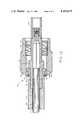
- FIG. 1is a cross-sectional view of a connector pin embodying the present invention
- FIG. 2is a cross-sectional view, to an enlarged scale, of an insert member embodying the present invention
- FIG. 3is a perspective view, to an enlarged scale, of a pin member which may be used in practicing the present invention
- FIG. 4is a cross-sectional view, to an enlarged scale, of the pin member of FIG. 3;
- FIG. 5is a cross-sectional view of a connector pin assembly embodying the present invention at one stage of its assembly
- FIG. 6is an end view of the connector pin assembly of FIG. 5;
- FIG. 7is a partial cross-sectional view of the connector pin assembly of FIG. 5 at a further stage of its assembly
- FIG. 8is a front end view of the connector pin assembly of FIG. 7;
- FIG. 9is a partial cross-sectional view of the connector pin assembly of FIG. 5 at a still further stage in the assembly of the connector pin assembly and the termination of an optical fiber;
- FIG. 10is an end view of the connector pin assembly as shown in FIG. 9;
- FIG. 11is a cross-sectional view of a completely assembled connector pin assembly and terminated optical fiber assembled in accordance with the present invention.
- FIG. 12is a cross-sectional view of a complete connector incorporating the connector pin assembly of the present invention.
- FIG. 1shows a connector pin which may be utilized in practicing the present invention.
- the pingenerally designated 20 comprises a stainless steel tubular body having a rear end 21 and a forward or terminating end 22.
- the tubular body 20includes a major diameter portion 23, an intermediate diameter portion 24, and a minor diameter portion 25.
- an annular flange 26Between major diameter portion 23 and intermediate diameter portion 24 is an annular flange 26 which may be received into a correspondingly shaped annular slot of a connector housing (not shown).
- One such connector housingis fully described and claimed in copending application Ser. No. 788,985, filed Apr. 19, 1977, in the names of John A. Makuch and Melvin Gordon, now U.S. Pat. No. 4,140,367 issued Feb.
- Pin 20also includes a longitudinal bore 30 which extends into the rear end of the tubular body and a counter bore 31 which extends into the forward end of the tubular body.
- Longitudinal bore 30includes conical sidewalls 30a which converge towards the forward end of pin 20 and a reduced diameter portion 30b which communicates with the counter bore 31.
- counter bore 31communicates with the longitudinal bore 30.
- the counter bore 31is dimensioned concentrically with the outer dimension of the minor diameter portion 25 and is also greater in diameter than the reduced diameter portion 30b of longitudinal bore 30.
- the counter bore 31 and the reduced diameter portion 30b of longitudinal bore 30define an annular shoulder portion 32 which is forward facing.
- the counter bore 31is dimensioned for receiving the insert member 35 shown in FIG. 2.
- the insert member 35preferably formed from stainless steel, has an outer diameter corresponding to the diameter of the counter bore 31 for being received by the counter bore 31.
- Insert member 35includes tapered side portions 36 which assist in the inserting of the insert member into counter bore 31.
- Insert member 35also includes a guide bore 37 which has a major opening 41 and converging sidewalls 38 converging in the direction towards the forward end of pin 20.
- the guide borealso includes a channel 39 which terminates in a slightly increased diameter opening 40. With the guide bore 37 being so constructed, insert member 35 assists in the threading of an optical fiber into the longitudinal bore in a manner to be described more fully hereinafter.
- FIGS. 3 and 4show a pin member which may be utilized in practicing the present invention.
- the pin member 45is formed from a solid tubular body preferably consisting of stainless steel.
- Pin member 45includes a cylindrical portion 46 and a conical end portion 47.
- the conical end portion 47has a conical outer surface 48 which decreases in diameter in the rearward direction.
- FIGS. 5 and 6illustrate the connector pin assembly after one stage of its assembly.
- Insert member 35 and four of pin members 45have been inserted into the counter bore 31.
- the insert member 35 as shownis within the counter bore between the forward shoulder 32 defined by the reduced diameter portion 30b of longitudinal bore 30 and counter bore 31, and the four pin members 45.
- the four pin members 45are arranged in side-by-side relation and, as best seen in FIG. 6, are arranged to be in tangential contact with counter bore 31 and tangential contact with each other.
- Th pin members 45are also of equal dimension and define a central passage 50.
- the central passageway 50will be centrally located within the pin 20 and an optical fiber inserted therein will be concentrically aligned with the outer dimension of the pin 20.
- the major opening 41 of insert member 35 defined by the conical sidewalls 38communicates with the reduced diameter portion 30b of longitudinal bore 30.
- the pin members 45are also arranged such that their conical end portions 47 point in the rearward direction so that the conical sidewalls 48 form converging guide walls for guiding an optical fiber into the central passageway 50. It is also noted that the forward ends of pin members 45 extend beyond the terminal end face 28 of pin 20.
- FIGS. 7 and 8illustrate the connector pin assembly after an optical fiber 60 has been inserted into the rear end of longitudinal bore 30 and threaded through the longitudinal bore, the insert member 35, and the central passageway 50 defined by the pin members 45.
- the optical fiber 60is threaded past the forward end face 28 of the pin 20.
- the diameter of the counter bore, and the diameter of the pin members 45are selected so that the optical fiber 60 will be in tangential contact with the pin members 45 as shown in FIG. 8. This tangential relation between the optical fiber 60, the pin members 45, and the counter bore 31 is preferred to assure that the optical fiber 60 will be concentrically aligned with respect to the outer dimension of minor diameter portion 25 of pin 20.
- a suitable adhesivesuch as epoxy is caused to flow into the forward end of the pin to permanently seal the optical fiber 60 in place.
- the connector pin assembly after this operationis illustrated in FIGS. 9 and 10. It has been found in practice that the epoxy will flow into the forward end of the pin assembly by way of capillary action.
- the epoxy 65is then allowed to cure, and as a result, the insert member 35, the pin members 45, and the optical fiber 60 are permanently secured and terminated within the counter bore 31.
- the portions of the pin members 45 and optical fiber 60 which extend beyond the terminal end face 28 of pin 20are ground off and polished into a smooth surface with the terminating end face 28 of pin 20.
- the resulting completed pin assemblyis shown in FIG. 11. If a fiber optic cable of the type having an outer protective sleeve 61 is to be terminated, the sleeve 61 may be removed at a point sufficiently spaced from the tip of the optical fiber to assure that the optical fiber will thread through the reduced diameter portion 30b, and the central passageway 50 defined by the pin members 45.
- the protective sleeve 61 as shown in FIG. 11has been removed at 62.
- the inventiontherefore provides a new and improved connector pin assembly for terminating and aligning an optical fiber concentrically with the outer dimension of the connector pin. While four pin members have been shown and described as the preferred embodiment herein, it must be understood that any number of pin members greater than two pin members may be utilized in practicing the present invention. Because the optical fiber is entirely enclosed within the tubular body of the pin, it is protected from dirt and other extraneous matter which may degrade light transfer between a pair of optical fiber terminated according to the present invention. It has also been found through practice, that any type of single optical fiber cable may be terminated in accordance with the present invention. Lastly, because the tubular body, the insert member, and the pin member are configured from stainless steel, the resulting connector pin assembly will not be subject to temperature or chemical environmental instabilities. Of course, other stable materials may also be used.
- the connector pin assembly of the present inventionis most suitably adapted for interconnecting a pair of optical fibers in the manner fully disclosed and claimed in the aforementioned patent application Ser. No. 788,820.
- the connector assembly there describedincludes a pin having a reduced diameter front end portion having a forward facing annular shoulder such as shoulder 27.
- a resilient sleeveis dimensioned for being tightly received over the reduced diameter portion of each pin and is of a predetermined length so that when the ends of the resilient sleeve abut the forward facing shoulders, the terminal end faces, such as terminal ends 28, will be a controlled and predetermined spacing to effect efficient light transfer.
- the counter bore 31is concentrically dimensioned with respect to the outer dimension of the pin 20, and because the pin members are of equal diameter and tangential contact with the counter bore, with each other, and with the optical fiber 60, the optical fiber of each pin will be accurately aligned with one another both axially and angularly to effect efficient light transfer.
- FIG. 12shows a complete fiber optic cable connector 70 incorporating the connector pin assembly of FIG. 11. It includes the complete connector pin assembly, a rear body portion 71, a retaining ring 72, a coupling nut 73, and a sleeve 74.
- the rear body portion 71is tubular and includes a rear bore portion 75 dimensioned for receiving the fiber optic cable sleeve 61, and a forward bore 76 dimensioned for tightly receiving the major diameter portion 23 of connector pin 20.
- the rear body portion 71has a forward annular face 77 which abuts the rearwardly facing shoulder 26a of annular flange 26.
- the rear body portion 71has an annular slot 78 which is dimensioned for receiving retaining ring 72 to axially fix the retaining ring therein.
- the retaining ring 72 and an annular flange 79coact to confine coupling nut 73 on the forward end of the rear body portion 71.
- coupling nut 73includes a reduced inner diameter portion 80 which is confined between retaining ring 72 and the annular flange 79, and a major inner diameter portion 81.
- Major diameter portion 81carries suitable inner threads for threading engagement with a complementary connector.
- sleeve 74preferably formed from resilient material, is tightly received on the forward end of pin 20 and arranged to receive the forward end of the pin carried by the complementary connector in the same manner.
- the sleevealigns and spaces the terminating end faces of the fiber optic cables for efficient light transfer.
- Strain reliefis afforded to the cable by adhering it to the rear body portion.
- a suitable adhesivesuch as epoxy 82 is caused to flow into the rear bore 75 around the cable and allowed to cure. In this manner, the cable is firmly fixed to the connector. Strain relief may also be provided by crimping the cable to the rear body portion in a known manner.
Landscapes
- Physics & Mathematics (AREA)
- General Physics & Mathematics (AREA)
- Optics & Photonics (AREA)
- Mechanical Coupling Of Light Guides (AREA)
Abstract
Description
Claims (10)
Priority Applications (6)
| Application Number | Priority Date | Filing Date | Title |
|---|---|---|---|
| US05/806,953US4183619A (en) | 1977-06-15 | 1977-06-15 | Connector pin assembly and method for terminating an optical fiber |
| CA305,186ACA1102599A (en) | 1977-06-15 | 1978-06-12 | Connector pin assembly and method for terminating an optical fiber |
| FR7817823AFR2394824A1 (en) | 1977-06-15 | 1978-06-14 | PIN CONNECTOR AND METHOD FOR CONNECTING AN OPTICAL FIBER |
| GB7827021AGB2000322B (en) | 1977-06-15 | 1978-06-15 | Connector pin assembly and method for terminating an optical fiber |
| JP7159478AJPS5439649A (en) | 1977-06-15 | 1978-06-15 | Method of terminating optical fiber and connector pin assemblage used therefor |
| DE19782826290DE2826290A1 (en) | 1977-06-15 | 1978-06-15 | CONNECTOR PLUG AND METHOD OF CONNECTING A FIBER OPTICAL CONDUCTOR |
Applications Claiming Priority (1)
| Application Number | Priority Date | Filing Date | Title |
|---|---|---|---|
| US05/806,953US4183619A (en) | 1977-06-15 | 1977-06-15 | Connector pin assembly and method for terminating an optical fiber |
Publications (1)
| Publication Number | Publication Date |
|---|---|
| US4183619Atrue US4183619A (en) | 1980-01-15 |
Family
ID=25195206
Family Applications (1)
| Application Number | Title | Priority Date | Filing Date |
|---|---|---|---|
| US05/806,953Expired - LifetimeUS4183619A (en) | 1977-06-15 | 1977-06-15 | Connector pin assembly and method for terminating an optical fiber |
Country Status (6)
| Country | Link |
|---|---|
| US (1) | US4183619A (en) |
| JP (1) | JPS5439649A (en) |
| CA (1) | CA1102599A (en) |
| DE (1) | DE2826290A1 (en) |
| FR (1) | FR2394824A1 (en) |
| GB (1) | GB2000322B (en) |
Cited By (27)
| Publication number | Priority date | Publication date | Assignee | Title |
|---|---|---|---|---|
| WO1982000720A1 (en)* | 1980-08-21 | 1982-03-04 | L Lidholt | Centering piece for a precision junction for optical fibres |
| US4339171A (en)* | 1978-02-21 | 1982-07-13 | Bunker Ramo Corporation | Fiber optic cable retainer member |
| US4440469A (en)* | 1980-09-18 | 1984-04-03 | Amp Incorporated | Optical waveguide connector |
| US4444461A (en)* | 1981-12-03 | 1984-04-24 | Augat Inc. | Fiber optic connector and method of manufacture |
| US4460243A (en)* | 1982-04-29 | 1984-07-17 | Times Fiber Communications, Inc. | Optical fiber connector |
| DE3408840A1 (en)* | 1983-03-14 | 1984-09-20 | Deutsche Itt Industries Gmbh, 7800 Freiburg | PLUG-IN COUPLING FOR LIGHT-WAVE GUIDE |
| US4486072A (en)* | 1982-01-12 | 1984-12-04 | Augat Inc. | Optical connector and splicing device using double diameter resilient rods |
| US4526438A (en)* | 1983-05-13 | 1985-07-02 | Allied Corporation | Alignment sleeve for fiber optic connectors |
| US4666239A (en)* | 1982-10-27 | 1987-05-19 | Lidholt Lars Rune | Method for connecting an optical fiber and connecting member and mounting means for carrying out said method |
| US4684212A (en)* | 1980-06-19 | 1987-08-04 | U.S. Philips Corporation | Detachable optical connector |
| EP0154262A3 (en)* | 1984-02-24 | 1987-09-23 | Asahi-Seiki Manufacturing Co.Ltd. | Ferrule for optical fiber connector |
| US4699454A (en)* | 1984-03-29 | 1987-10-13 | American Telephone And Telegraph Company, At&T Bell Laboratories | Fiber optic connector |
| US4746194A (en)* | 1984-07-17 | 1988-05-24 | Peter Rasmussen | Method of mounting an end portion of an optical fibre in an optical fibre connector |
| US4755019A (en)* | 1986-08-16 | 1988-07-05 | W. C. Heraeus Gmbh | Optical fiber coupling |
| US4836637A (en)* | 1986-05-21 | 1989-06-06 | Poorman Thomas J | Expanded-beam fiber-optic connector |
| EP0457282A3 (en)* | 1990-05-16 | 1992-01-15 | Hirose Electric Co., Ltd. | Optical fiber connector terminal and method of making same |
| US5111521A (en)* | 1990-05-16 | 1992-05-05 | Hirose Electric Co. Ltd. | Optical fiber connector terminal and method of making same |
| US5111520A (en)* | 1990-05-16 | 1992-05-05 | Hirose Electric Co., Ltd. | Optical fiber connector terminal |
| US5119456A (en)* | 1990-05-16 | 1992-06-02 | Hirose Electric Co., Ltd. | Optical fiber connector terminal and method of making same |
| US6282349B1 (en)* | 2000-02-17 | 2001-08-28 | Stephen Griffin | Launch fiber termination |
| US20040130703A1 (en)* | 2003-01-03 | 2004-07-08 | Brown Matthew A. | Fiber optic guide pin |
| EP1482337A1 (en)* | 2003-05-30 | 2004-12-01 | TRUMPF Laser GmbH + Co.KG | Optical waveguide connector and method of production |
| US20080245836A1 (en)* | 2005-09-23 | 2008-10-09 | Oxford Fiber Ltd | Cleaving Apparatus |
| US20090180745A1 (en)* | 2007-12-21 | 2009-07-16 | Zerfas Jeffrey W | Methods and apparatus related to a launch connector portion of a ureteroscope laser-energy-delivery device |
| US20090299352A1 (en)* | 2007-12-21 | 2009-12-03 | Boston Scientific Scimed, Inc. | Steerable laser-energy delivery device |
| US20130071069A1 (en)* | 2011-09-15 | 2013-03-21 | Hon Hai Precision Industry Co., Ltd. | Optical fiber connector |
| US9933571B2 (en) | 2012-04-02 | 2018-04-03 | Oxford Fiber Ltd. | Profiling of cleaved angled end faces of optical fiber(s) |
Families Citing this family (5)
| Publication number | Priority date | Publication date | Assignee | Title |
|---|---|---|---|---|
| SE426882B (en)* | 1979-02-16 | 1983-02-14 | Stratos Ab | SET AND DEVICE FOR CONNECTING OPTICAL FIBERS |
| JPS5849921U (en)* | 1981-09-29 | 1983-04-04 | 須藤 源一 | Coin purse |
| JPS5863907A (en)* | 1981-10-14 | 1983-04-16 | Toyo Tanshi Kk | Optical connector |
| JPS60104912A (en)* | 1983-11-11 | 1985-06-10 | Takashi Mori | Photoconductor pipe and its connector |
| JPH0593823A (en)* | 1991-02-21 | 1993-04-16 | Hirose Electric Co Ltd | Optical fiber connector terminal |
Citations (9)
| Publication number | Priority date | Publication date | Assignee | Title |
|---|---|---|---|---|
| US3914015A (en)* | 1974-10-15 | 1975-10-21 | Itt | Fiber optic connector and assembly method |
| US3923371A (en)* | 1974-03-22 | 1975-12-02 | Northern Electric Co | Optical fibre connectors |
| US3960531A (en)* | 1975-07-28 | 1976-06-01 | Corning Glass Works | Method and apparatus for splicing optical fibers |
| US3989567A (en)* | 1974-06-20 | 1976-11-02 | Compagnie Generale D'electricite | Connection method for two optical fibers having the same diameter |
| US4019241A (en)* | 1975-11-10 | 1977-04-26 | Thomas & Betts Corporation | Method of splicing elongate members |
| US4047796A (en)* | 1975-09-15 | 1977-09-13 | International Telephone And Telegraph Corporation | Precision optical fiber connector |
| US4050781A (en)* | 1974-11-13 | 1977-09-27 | Societe Anonyme Dite: Compagnie Industrielle Des Telecommunications Cit-Alcatel | Connector for optical fibers |
| US4056305A (en)* | 1976-04-26 | 1977-11-01 | International Telephone And Telegraph Corporation | Single optical fiber connector utilizing elastomeric alignment device |
| US4094580A (en)* | 1976-12-27 | 1978-06-13 | Bell Telephone Laboratories, Incorporated | Hermaphrodite optical fiber connector |
Family Cites Families (9)
| Publication number | Priority date | Publication date | Assignee | Title |
|---|---|---|---|---|
| JPS50136045A (en)* | 1974-04-15 | 1975-10-28 | ||
| GB1458897A (en)* | 1974-07-09 | 1976-12-15 | Cannon Electric Great Britain | Connectors |
| CA1053491A (en)* | 1974-08-19 | 1979-05-01 | Robert M. Hawk | Optical waveguide connector |
| DE2546449A1 (en)* | 1974-10-29 | 1976-05-13 | Itt Ind Gmbh Deutsche | CONNECTOR ARRANGEMENT FOR LIGHT GUIDE CABLES |
| GB1454600A (en)* | 1974-11-08 | 1976-11-03 | Plessey Co Ltd | Optical fibre connector doll' |
| FR2292989A1 (en)* | 1974-11-29 | 1976-06-25 | Thomson Csf | CONNECTOR FOR OPTICAL FIBER |
| GB1463350A (en)* | 1974-12-05 | 1977-02-02 | Bowthorpe Hellermann Ltd | Light guide contact |
| US3990779A (en)* | 1975-07-24 | 1976-11-09 | International Telephone And Telegraph Corporation | Single optical fiber connector |
| FR2386061A1 (en)* | 1977-03-31 | 1978-10-27 | Felten & Guilleaume Carlswerk | COUPLING DEVICE FOR LIGHT CONDUCTING FIBERS |
- 1977
- 1977-06-15USUS05/806,953patent/US4183619A/ennot_activeExpired - Lifetime
- 1978
- 1978-06-12CACA305,186Apatent/CA1102599A/ennot_activeExpired
- 1978-06-14FRFR7817823Apatent/FR2394824A1/enactiveGranted
- 1978-06-15DEDE19782826290patent/DE2826290A1/enactiveGranted
- 1978-06-15GBGB7827021Apatent/GB2000322B/ennot_activeExpired
- 1978-06-15JPJP7159478Apatent/JPS5439649A/enactiveGranted
Patent Citations (9)
| Publication number | Priority date | Publication date | Assignee | Title |
|---|---|---|---|---|
| US3923371A (en)* | 1974-03-22 | 1975-12-02 | Northern Electric Co | Optical fibre connectors |
| US3989567A (en)* | 1974-06-20 | 1976-11-02 | Compagnie Generale D'electricite | Connection method for two optical fibers having the same diameter |
| US3914015A (en)* | 1974-10-15 | 1975-10-21 | Itt | Fiber optic connector and assembly method |
| US4050781A (en)* | 1974-11-13 | 1977-09-27 | Societe Anonyme Dite: Compagnie Industrielle Des Telecommunications Cit-Alcatel | Connector for optical fibers |
| US3960531A (en)* | 1975-07-28 | 1976-06-01 | Corning Glass Works | Method and apparatus for splicing optical fibers |
| US4047796A (en)* | 1975-09-15 | 1977-09-13 | International Telephone And Telegraph Corporation | Precision optical fiber connector |
| US4019241A (en)* | 1975-11-10 | 1977-04-26 | Thomas & Betts Corporation | Method of splicing elongate members |
| US4056305A (en)* | 1976-04-26 | 1977-11-01 | International Telephone And Telegraph Corporation | Single optical fiber connector utilizing elastomeric alignment device |
| US4094580A (en)* | 1976-12-27 | 1978-06-13 | Bell Telephone Laboratories, Incorporated | Hermaphrodite optical fiber connector |
Non-Patent Citations (2)
| Title |
|---|
| C. M. Miller, "Optical Fiber Splicing Topical Meeting on Optical Fiber Transmission II, Feb. 1977, paper No. WA3.* |
| Fenten et al., "Connecting the Thread of Light", Electronic Connector Study Group, 9th Symposium, Oct. 1976, pp. 63-72.* |
Cited By (38)
| Publication number | Priority date | Publication date | Assignee | Title |
|---|---|---|---|---|
| US4339171A (en)* | 1978-02-21 | 1982-07-13 | Bunker Ramo Corporation | Fiber optic cable retainer member |
| US4684212A (en)* | 1980-06-19 | 1987-08-04 | U.S. Philips Corporation | Detachable optical connector |
| WO1982000720A1 (en)* | 1980-08-21 | 1982-03-04 | L Lidholt | Centering piece for a precision junction for optical fibres |
| US4440469A (en)* | 1980-09-18 | 1984-04-03 | Amp Incorporated | Optical waveguide connector |
| US4444461A (en)* | 1981-12-03 | 1984-04-24 | Augat Inc. | Fiber optic connector and method of manufacture |
| US4486072A (en)* | 1982-01-12 | 1984-12-04 | Augat Inc. | Optical connector and splicing device using double diameter resilient rods |
| US4460243A (en)* | 1982-04-29 | 1984-07-17 | Times Fiber Communications, Inc. | Optical fiber connector |
| US4666239A (en)* | 1982-10-27 | 1987-05-19 | Lidholt Lars Rune | Method for connecting an optical fiber and connecting member and mounting means for carrying out said method |
| DE3408840A1 (en)* | 1983-03-14 | 1984-09-20 | Deutsche Itt Industries Gmbh, 7800 Freiburg | PLUG-IN COUPLING FOR LIGHT-WAVE GUIDE |
| US4526438A (en)* | 1983-05-13 | 1985-07-02 | Allied Corporation | Alignment sleeve for fiber optic connectors |
| EP0154262A3 (en)* | 1984-02-24 | 1987-09-23 | Asahi-Seiki Manufacturing Co.Ltd. | Ferrule for optical fiber connector |
| US4699454A (en)* | 1984-03-29 | 1987-10-13 | American Telephone And Telegraph Company, At&T Bell Laboratories | Fiber optic connector |
| EP0177612B1 (en)* | 1984-03-29 | 1990-08-08 | AT&T Corp. | Fiber optic connector |
| US4746194A (en)* | 1984-07-17 | 1988-05-24 | Peter Rasmussen | Method of mounting an end portion of an optical fibre in an optical fibre connector |
| US4836637A (en)* | 1986-05-21 | 1989-06-06 | Poorman Thomas J | Expanded-beam fiber-optic connector |
| US4755019A (en)* | 1986-08-16 | 1988-07-05 | W. C. Heraeus Gmbh | Optical fiber coupling |
| US5111520A (en)* | 1990-05-16 | 1992-05-05 | Hirose Electric Co., Ltd. | Optical fiber connector terminal |
| EP0457282A3 (en)* | 1990-05-16 | 1992-01-15 | Hirose Electric Co., Ltd. | Optical fiber connector terminal and method of making same |
| US5113465A (en)* | 1990-05-16 | 1992-05-12 | Hirose Electric Co., Ltd. | Optical fiber connector terminal and method of making same |
| US5119456A (en)* | 1990-05-16 | 1992-06-02 | Hirose Electric Co., Ltd. | Optical fiber connector terminal and method of making same |
| US5111521A (en)* | 1990-05-16 | 1992-05-05 | Hirose Electric Co. Ltd. | Optical fiber connector terminal and method of making same |
| US6282349B1 (en)* | 2000-02-17 | 2001-08-28 | Stephen Griffin | Launch fiber termination |
| US20040130703A1 (en)* | 2003-01-03 | 2004-07-08 | Brown Matthew A. | Fiber optic guide pin |
| US6886988B2 (en)* | 2003-01-03 | 2005-05-03 | Matthew A. Brown | Fiber optic guide pin |
| EP1482337A1 (en)* | 2003-05-30 | 2004-12-01 | TRUMPF Laser GmbH + Co.KG | Optical waveguide connector and method of production |
| US7134795B1 (en) | 2003-05-30 | 2006-11-14 | Trumpf Laser Gmbh + Co. Kg | Optical fiber connector arrangement |
| US8069691B2 (en)* | 2005-09-23 | 2011-12-06 | Oxford Fiber Ltd. | Cleaving apparatus |
| US20080245836A1 (en)* | 2005-09-23 | 2008-10-09 | Oxford Fiber Ltd | Cleaving Apparatus |
| US20090180745A1 (en)* | 2007-12-21 | 2009-07-16 | Zerfas Jeffrey W | Methods and apparatus related to a launch connector portion of a ureteroscope laser-energy-delivery device |
| US20090299352A1 (en)* | 2007-12-21 | 2009-12-03 | Boston Scientific Scimed, Inc. | Steerable laser-energy delivery device |
| US8419293B2 (en) | 2007-12-21 | 2013-04-16 | Boston Scientific Scimed, Inc. | Methods and apparatus related to a launch connector portion of a ureteroscope laser-energy-delivery device |
| US8888378B2 (en) | 2007-12-21 | 2014-11-18 | Boston Scientific Scimed, Inc. | Methods and apparatus related to a launch connector portion of a ureteroscope laser-energy-delivery device |
| US9329350B2 (en) | 2007-12-21 | 2016-05-03 | Boston Scientific Scimed, Inc. | Methods and apparatus related to a launch connector portion of a ureteroscope laser-energy-delivery device |
| US9519107B2 (en) | 2007-12-21 | 2016-12-13 | Boston Scientific Scimed, Inc. | Methods and apparatus related to a launch connector portion of a ureteroscope laser-energy-delivery device |
| US20130071069A1 (en)* | 2011-09-15 | 2013-03-21 | Hon Hai Precision Industry Co., Ltd. | Optical fiber connector |
| US8636423B2 (en)* | 2011-09-15 | 2014-01-28 | Hon Hai Precision Industry Co., Ltd. | Optical fiber connector with positioning members |
| TWI491940B (en)* | 2011-09-15 | 2015-07-11 | Hon Hai Prec Ind Co Ltd | Optical fiber coupling connector |
| US9933571B2 (en) | 2012-04-02 | 2018-04-03 | Oxford Fiber Ltd. | Profiling of cleaved angled end faces of optical fiber(s) |
Also Published As
| Publication number | Publication date |
|---|---|
| JPS5439649A (en) | 1979-03-27 |
| GB2000322A (en) | 1979-01-04 |
| FR2394824A1 (en) | 1979-01-12 |
| FR2394824B1 (en) | 1983-06-17 |
| CA1102599A (en) | 1981-06-09 |
| JPS612924B2 (en) | 1986-01-29 |
| GB2000322B (en) | 1982-03-17 |
| DE2826290C2 (en) | 1987-10-29 |
| DE2826290A1 (en) | 1979-01-04 |
Similar Documents
| Publication | Publication Date | Title |
|---|---|---|
| US4183619A (en) | Connector pin assembly and method for terminating an optical fiber | |
| US4208092A (en) | Fiber optic multi-cable pair connector | |
| US4190317A (en) | Fiber optic cable connector pin assembly | |
| US3963323A (en) | Fiber optic connector with protective cable sleeves | |
| US4140366A (en) | Fiber optic connector assembly | |
| US4140367A (en) | Multiple channel connector for fiber optic cables | |
| US5971626A (en) | Fiber optic connector and connector sleeve assembly | |
| US4127319A (en) | Termination means for fiber optic bundle | |
| US4773725A (en) | Termination of a fiber optic transmission member and method therefore | |
| US4279466A (en) | Hermaphroditic fiber optic connector | |
| US4303304A (en) | Universal optical waveguide alignment ferrule | |
| CA1068952A (en) | Single optical fiber connector | |
| US4836637A (en) | Expanded-beam fiber-optic connector | |
| US3984174A (en) | Fiber optic connector with transparent cable sleeve | |
| US4526438A (en) | Alignment sleeve for fiber optic connectors | |
| US5140661A (en) | Optical fiber terminus | |
| US4483584A (en) | Optical fiber connector | |
| EP0192735A1 (en) | A connector for an optical fiber. | |
| US4192575A (en) | Guide-connector assembly for joining optical fibers and method of making guide therefor | |
| EP0039954A1 (en) | Optical fiber connector construction | |
| GB1561838A (en) | Terminating optical fibes | |
| GB1583612A (en) | Connectors for optical conductors | |
| US4398796A (en) | Optical fibre termination | |
| US4892379A (en) | Fiber optic connector | |
| CA1090638A (en) | Multiple channel connector for fiber optic cables |
Legal Events
| Date | Code | Title | Description |
|---|---|---|---|
| AS | Assignment | Owner name:ALLIED CORPORATION COLUMBIA ROAD AND PARK AVENUE, Free format text:ASSIGNMENT OF ASSIGNORS INTEREST.;ASSIGNOR:BUNKER RAMO CORPORATION A CORP. OF DE;REEL/FRAME:004149/0365 Effective date:19820922 | |
| AS | Assignment | Owner name:CANADIAN IMPERIAL BANK OF COMMERCE, NEW YORK AGENC Free format text:SECURITY INTEREST;ASSIGNOR:AMPHENOL CORPORATION;REEL/FRAME:004879/0030 Effective date:19870515 | |
| AS | Assignment | Owner name:AMPHENOL CORPORATION, LISLE, ILLINOIS A CORP. OF D Free format text:ASSIGNMENT OF ASSIGNORS INTEREST.;ASSIGNOR:ALLIED CORPORATION, A CORP. OF NY;REEL/FRAME:004844/0850 Effective date:19870602 Owner name:AMPHENOL CORPORATION, A CORP. OF DE, ILLINOIS Free format text:ASSIGNMENT OF ASSIGNORS INTEREST;ASSIGNOR:ALLIED CORPORATION, A CORP. OF NY;REEL/FRAME:004844/0850 Effective date:19870602 | |
| AS | Assignment | Owner name:BANKERS TRUST COMPANY, AS AGENT Free format text:SECURITY INTEREST;ASSIGNOR:AMPHENOL CORPORATION, A CORPORATION OF DE;REEL/FRAME:006035/0283 Effective date:19911118 | |
| AS | Assignment | Owner name:AMPHENOL CORPORATION A CORP. OF DELAWARE Free format text:RELEASED BY SECURED PARTY;ASSIGNOR:CANADIAN IMPERIAL BANK OF COMMERCE;REEL/FRAME:006147/0887 Effective date:19911114 | |
| AS | Assignment | Owner name:AMPHENOL CORPORATION, CONNECTICUT Free format text:RELEASE BY SECURED PARTY;ASSIGNOR:BANKERS TRUST COMPANY;REEL/FRAME:007317/0148 Effective date:19950104 |