US4182328A - Dispensing instrument and method - Google Patents
Dispensing instrument and methodDownload PDFInfo
- Publication number
- US4182328A US4182328AUS05/854,081US85408177AUS4182328AUS 4182328 AUS4182328 AUS 4182328AUS 85408177 AUS85408177 AUS 85408177AUS 4182328 AUS4182328 AUS 4182328A
- Authority
- US
- United States
- Prior art keywords
- piston
- cylinder
- sleeve
- instrument
- chamber
- Prior art date
- Legal status (The legal status is an assumption and is not a legal conclusion. Google has not performed a legal analysis and makes no representation as to the accuracy of the status listed.)
- Expired - Lifetime
Links
- 238000000034methodMethods0.000titleclaimsabstractdescription12
- 239000000463materialSubstances0.000claimsabstractdescription59
- 239000000523sampleSubstances0.000claimsabstractdescription58
- 210000003101oviductAnatomy0.000claimsabstractdescription25
- 238000003780insertionMethods0.000claimsabstractdescription9
- 230000037431insertionEffects0.000claimsabstractdescription9
- 239000012530fluidSubstances0.000claimsabstractdescription8
- 238000007789sealingMethods0.000claimsdescription16
- 210000004291uterusAnatomy0.000claimsdescription8
- 230000006835compressionEffects0.000claims2
- 238000007906compressionMethods0.000claims2
- 238000007599dischargingMethods0.000claims1
- 238000013022ventingMethods0.000claims1
- 239000003708ampulSubstances0.000abstractdescription23
- 239000003814drugSubstances0.000abstractdescription16
- 229940079593drugDrugs0.000abstractdescription16
- 210000003679cervix uteriAnatomy0.000description5
- 210000005069earsAnatomy0.000description5
- 239000011888foilSubstances0.000description4
- 241000288906PrimatesSpecies0.000description2
- 230000000712assemblyEffects0.000description2
- 238000000429assemblyMethods0.000description2
- 210000004996female reproductive systemAnatomy0.000description2
- 210000003205muscleAnatomy0.000description2
- 210000004994reproductive systemAnatomy0.000description2
- 239000003106tissue adhesiveSubstances0.000description2
- 210000001215vaginaAnatomy0.000description2
- 239000000853adhesiveSubstances0.000description1
- 230000001070adhesive effectEffects0.000description1
- 230000003444anaesthetic effectEffects0.000description1
- 229960000074biopharmaceuticalDrugs0.000description1
- 238000004891communicationMethods0.000description1
- 239000003433contraceptive agentSubstances0.000description1
- 230000002254contraceptive effectEffects0.000description1
- 230000000694effectsEffects0.000description1
- 230000004720fertilizationEffects0.000description1
- 239000002184metalSubstances0.000description1
- 210000000056organAnatomy0.000description1
- 238000005086pumpingMethods0.000description1
- 230000035945sensitivityEffects0.000description1
- 210000001519tissueAnatomy0.000description1
- 229940075469tissue adhesivesDrugs0.000description1
- 230000000007visual effectEffects0.000description1
Images


Classifications
- A—HUMAN NECESSITIES
- A61—MEDICAL OR VETERINARY SCIENCE; HYGIENE
- A61M—DEVICES FOR INTRODUCING MEDIA INTO, OR ONTO, THE BODY; DEVICES FOR TRANSDUCING BODY MEDIA OR FOR TAKING MEDIA FROM THE BODY; DEVICES FOR PRODUCING OR ENDING SLEEP OR STUPOR
- A61M25/00—Catheters; Hollow probes
- A61M25/10—Balloon catheters
- A—HUMAN NECESSITIES
- A61—MEDICAL OR VETERINARY SCIENCE; HYGIENE
- A61F—FILTERS IMPLANTABLE INTO BLOOD VESSELS; PROSTHESES; DEVICES PROVIDING PATENCY TO, OR PREVENTING COLLAPSING OF, TUBULAR STRUCTURES OF THE BODY, e.g. STENTS; ORTHOPAEDIC, NURSING OR CONTRACEPTIVE DEVICES; FOMENTATION; TREATMENT OR PROTECTION OF EYES OR EARS; BANDAGES, DRESSINGS OR ABSORBENT PADS; FIRST-AID KITS
- A61F6/00—Contraceptive devices; Pessaries; Applicators therefor
- A61F6/20—Vas deferens occluders; Fallopian occluders
- A61F6/22—Vas deferens occluders; Fallopian occluders implantable in tubes
- A61F6/225—Vas deferens occluders; Fallopian occluders implantable in tubes transcervical
- A—HUMAN NECESSITIES
- A61—MEDICAL OR VETERINARY SCIENCE; HYGIENE
- A61M—DEVICES FOR INTRODUCING MEDIA INTO, OR ONTO, THE BODY; DEVICES FOR TRANSDUCING BODY MEDIA OR FOR TAKING MEDIA FROM THE BODY; DEVICES FOR PRODUCING OR ENDING SLEEP OR STUPOR
- A61M31/00—Devices for introducing or retaining media, e.g. remedies, in cavities of the body
- Y—GENERAL TAGGING OF NEW TECHNOLOGICAL DEVELOPMENTS; GENERAL TAGGING OF CROSS-SECTIONAL TECHNOLOGIES SPANNING OVER SEVERAL SECTIONS OF THE IPC; TECHNICAL SUBJECTS COVERED BY FORMER USPC CROSS-REFERENCE ART COLLECTIONS [XRACs] AND DIGESTS
- Y10—TECHNICAL SUBJECTS COVERED BY FORMER USPC
- Y10S—TECHNICAL SUBJECTS COVERED BY FORMER USPC CROSS-REFERENCE ART COLLECTIONS [XRACs] AND DIGESTS
- Y10S604/00—Surgery
- Y10S604/904—Tampons
Definitions
- Dispensing instruments and methods of introducing fluids and fluid-like materials, as drug material, into the canals of Fallopian tubesare disclosed by Bolduc and Dickhudt in U.S. Pat. Nos. 3,822,702, 3,871,374, 3,875,939, and 3,948,259. These instruments have elongated probes with a forward end carrying expandable balloon assemblies. Dispensing structure located within the housings are used to expand the balloon assemblies and discharge drug material into the uterine cavity. The drug material to be discharged into the uterine cavity is stored in a container accommodated by the dispensing structure. In the use of these dispensing instruments, it is found that the cervices of females have different sizes and strengths.
- the uterine cavitieshave different shapes and elongated sections leading to the canals of the Fallopian tubes. Under certain circumstances, it is difficult to insert the balloon assembly through the cervical opening into the uterine cavity. The tight relationship between the balloon assembly and the cervical opening causes any air that is located in the balloon assembly to expand, increasing the difficulty of inserting the balloon assembly through the cervical opening into the uterine cavity.
- the inventionis directed to an apparatus and method for dispensing fluid and fluid-like materials, as a drug material, into the canals of the Fallopian tubes of a primate female.
- the instrumenthas a housing carrying an elongated flexible probe.
- An expandable cylindrical balloon or sleeve attached to the outer end of the probeis used to move material dispensed in the uterine cavity into the canals of the Fallopian tubes.
- a piston and cylinder assembly operably associated with the housingis used to partially expand the balloon, dispense the material into the uterine cavity, and then fully expand the sleeve to move the material from the uterine cavity into the canals of the Fallopian tubes.
- the piston and cylinder assemblyhas a piston that is slidably located within a cylinder.
- the piston and cylinderhave coacting means operable to vent air from the sleeve chamber when the piston is in its first full in position and establish a vacuum force on the balloon when the piston is moved away from the first position to fully collapse the sleeve on the probe.
- the fully collapsed sleeveis inserted through the cervical opening into the uterine cavity. This insertion is facilitated as the sleeve has a minimum annular size and there is no air to expand the sleeve as it is inserted through the cervical opening into the uterine cavity.
- the instrumentis then operated to initially partially expand the sleeve, introduce the material into the uterine cavity, and then fully expand the sleeve to move the material from the uterine cavity into the canals of the Fallopian tubes. Substantially all of the material introduced into the uterine cavity is moved by the expanding sleeve into the canals of the Fallopian tubes in a short period of time. When the material like a tissue adhesive is placed in the canals, it reacts with the tissue to polymerize the adhesive and thereby occludes the canals. After the material has been moved into the canals of the Fallopian tubes, the sleeve is collapsed so that the probe and balloon can be readily withdrawn from the uterine cavity.
- FIG. 1is a perspective view of the dispensing instrument of the invention and an ampulla usable with the instrument;
- FIG. 2is a top plan view of the dispensing instrument of FIG. 1 in its storage and shipping condition;
- FIG. 3is a plan view of the dispensing instrument with the top housing removed and the piston of the piston and cylinder assembly in the out position;
- FIG. 4is an end elevational view of the right end of FIG. 2;
- FIG. 5is an enlarged sectional view taken along line 5--5 of FIG. 4 with the piston of the piston and cylinder assembly in the out position;
- FIG. 6is a view similar to FIG. 3, partly sectioned with the piston of the piston and cylinder assembly in the full in position;
- FIG. 7is a view similar to FIG. 6 with the piston of the piston and cylinder assembly located in an intermediate position;
- FIG. 8is a view similar to FIG. 6 with the piston and cylinder assembly located in the in material dispensing position;
- FIG. 9is an enlarged side view of the piston of the piston and cylinder assembly
- FIG. 10is an end view of the left end of FIG. 9;
- FIG. 11is a bottom view of FIG. 9;
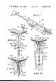
- FIG. 12is a perspective view of the ampulla
- FIG. 13is an enlarged sectional view taken along line 13--13 of FIG. 12;
- FIG. 14is an enlarged foreshortened sectional view of the piston and cylinder assembly and balloon attached to the probe;
- FIG. 15is a sectional view of the female reproductive system prior to the insertion of the probe into the uterine cavity
- FIG. 16is a view similar to FIG. 15 with the probe inserted into the uterine cavity and the balloon partially expanded;
- FIG. 17is a view similar to FIG. 16 with the balloon fully expanded.
- FIG. 1the material dispensing instrument of the invention indicated generally at 20 operable to transfer fluid and fluid-like materials, as drug materials, into both canals of the Fallopian tubes of a reproductive system of a female.
- Instrument 20has a housing or casing 21 accommodating a piston and cylinder assembly 22.
- An elongated flexible probe 23is secured to and extends away from the forward end of housing 21 generally along the longitudinal axis of the housing.
- An expandable balloon or cylindrical sleeve 24is mounted on the forward end of probe 23.
- Sleeve 24is an expandable elastic tubular sheet member attached at its opposite ends to the probe.
- the material to be dispensed by the instrumentis stored in an ampulla or container 26.
- Housing 21has a T-shaped opening 27 to facilitate the correct loading of the ampulla 26 into the instrument. Ampulla 26 can only be loaded in one position in the instrument.
- sleeve 24is shown in a contracted position.
- An elongated cylindrical cover 28 shown in broken linesis located over sleeve 24 and probe 23 to protect and maintain the sterile condition of the sleeve and probe.
- the open end of cover 28is mounted on an annular shoulder 29 secured to the forward end of housing 21.
- Cover 28is a shipping guard which encloses sleeve 24 and probe 23.
- Assembly 22, as shown in FIG. 2is located in the shipping position, which prevents entrance of air into the chamber 41 surrounded by sleeve 24.
- housing 21has an inside chamber or cavity 31 accommodating piston and cylinder assembly 22.
- the forward end of assembly 22bears against a fixed transverse wall 32 adjacent the forward end of housing 21.
- Assembly 22includes a cylinder 33 having a closed forward end or bottom wall 34 surrounding a cylinder chamber 35.
- the inside side wall of cylinder 33 adjacent wall 34has an annular pressure release groove 36, the function of which will be hereinafter described.
- a short cylindrical boss 37extends inwardly from the center of wall 32.
- the inner end of probe 23is mounted in boss 37 and provides an air passage 38 from cylinder chamber 35 to the chamber 41 surrounded by sleeve 24.
- the outer end of probe 23has one or more holes 39 providing access for the flow of air from passage 38 into the sleeve chamber 41 formed by sleeve 24.
- Assembly 22also includes a piston 42 slidably located in cylinder 33.
- Piston 42has a closed forward end or head 43.
- Head 43has a forwardly open bore or recess 44 for accommodating boss 37 when the piston 42 is in the full in position.
- Head 43also has an annular outwardly open groove 46 accommodating a sealing or O-ring seal 47.
- the face of head 43has a recess or cut-out segment 48 open to the groove 46 and a short radial vent passage 49 connecting recess 44 to the annular groove 46. Cut-out segment 48 and passage 49 connecting recess 44 to the annular groove 46. Cut-out segment 48 and passage 49 provides an air passage between recess 44 and seal groove 46.
- an actuator 51 having an elongated cylindrical tubular bodyis slidably located within piston 42.
- an elongated longitudinal rib 52extends downwardly from actuator 51.
- the forward end of rib 52is connected to a pair of downwardly directed ears 53.
- the ears 53extend through a longitudinal slot 54 in the bottom of side of piston 42.
- Actuator 51projects through a hole 56 in the rear end wall 57 of housing 21.
- Actuator 51is movable into the housing 21 to move the piston 42 to a first full in position close to the bottom of cylinder 33.
- piston 42has a pair of inwardly directed lips 58 located adjacent opposite sides of rib 52.
- Lips 58are engaged by ears 53 to limit the outward movement of actuator 51 relative to piston 52.
- a coil spring 59located longitudinally within piston 52 and actuator 51 biases piston 52 and actuator 51 in opposite directions. Lips 58 function as stops to hold piston 52 and actuator 51 in their relative extended positions.
- a finger ring 61shown in FIGS. 1, 2, and 4, is integral with the rear or outside end of actuator 51. Ring 61 is used by the hand of the operator to move the actuator 51 into and out of housing 21 during the dispensing procedure.
- a support 62 located adjacent wall 32carries a longitudinal tubular needle 63.
- Needle 63has a sharp forward or inlet end 64.
- the opposite end of needle 63is connected to a tube or hose 66.
- Hose 66extends through a post or support 67 integral with the forward end of housing 21.
- Post 67also supports probe 23.
- Tube 66extends through a closed hole 68 into passage 38 of probe 23.
- the outlet end 69 of tube 66is mounted in a plug 71 fitted into the remote or forward end of probe 23. Plug 71 also closes the air passage 38 of probe 23.
- a cradle or holder 72 for accommodating ampulla 26is located immediately in front of the needle point 64.
- Cradle 72is integral with a portion of housing 21 and faces the loading opening 27 in housing 21.
- an elongated linear push rod 73is slidably mounted for linear movement between a pair of ribs 74 integral with housing 21.
- Push rod 73is in general longitudinal alignment with needle 63 and functions to move the ampulla 26 into the needle 63 and forces the material stored in the ampulla through the needle 63 and tube 66 and out outlet end 69.
- Push rod 73is integral with a linear flexible neck 76.
- the neck 76terminates in head 77 that cooperates with actuator 51 to control the movement of push rod 73.
- Head 77has a first ear 78 located in a notch 79 in rib 52 between ears 53.
- Head 77has a second ear 81 that extends in a direction opposite the first ear 78 and rides on a linear edge 82 on the inside wall of housing 21.
- Edge 82has a forward shoulder 83 for accommodating ear 81 on inward movement of actuator 51 and piston 42.
- ampulla 26has a cylindrical side wall 84 integral with an end wall 86.
- the center of end wall 86has a hole 87 to accommodate the forward end of needle 63.
- the opposite end of the side wall 84is open and surrounded by a large radially outwardly directed portion or flange 89.
- the material 91 to be dispensed, as drug material,is located in the chamber surrounded by side wall 84.
- a movable plug or piston 92is located in a sealing relationship with the inside wall of side wall 84 which stores the material 91 in the ampulla.
- the forward end of 86is sealed with a foil seal member such as metal foil 93.
- the foil 93extends outside of the side wall 84 into an annular groove 94.
- Flange 89 on side wall 84has an outside diameter that is larger than the narrow portion of T-slot 27 in housing 21. Flange 89 fits through the enlarged portion of the T-slot. This prevents the ampulla 26 from being loaded backwards into the instrument.
- probe 23is an elongated flexible tubular member.
- probe 23is a plastic member having visual indicia marks indicating the insert position of sleeve 24 in the uterine cavity.
- Balloon or sleeve 24is a flexible, elastic and expandable cylindrical sheet member or rubber or rubber-like material. The inner end of the sheet member is clamped in a sealing relationship about the probe 23 with an annular sleeve 96. The outer end of sleeve 24 is sealed to the tip of probe 23 with a pair of annular sealing members 97, as clamp cords or the like.
- a female reproductive systemindicated generally at 100 of a primate female for receiving the sleeve end of probe 23.
- the reproductive system 100has a uterus 101 joined to a pair of Fallopian tubes 102 and 103.
- the lower part of uterus 101is integral with an elongated vagina 104.
- Vagina 104has a vaginal cavity 106 and an entrance or vestibule 107.
- the opposite end of vaginal cavity 106is in communication with the cervix 108.
- the cervix 108has a normally closed exit opening 109 providing a passage from vaginal cavity 106 to the uterine cavity 111.
- the Fallopian tubes 102 and 103have passages which exit at 112 and 113 into the uterine cavity 111.
- Uterus 101is a generally pear-shaped, thick walled, hollow organ.
- the uteri of femalesvary in size and shape. Wall thickness, wall strength and sensitivity to pain varies from female to female.
- the size and configuration of the uterine cavity 111varies in females.
- the uterine cavity 111is generally flat and triangular in shape. Other sizes and shapes of the uterine cavities have been noted.
- the exit sections of the canals 112 and 113 open to the uterine cavity 111may be enlarged and elongated and are in effect an extension of the uterine cavity.
- Uterus 101has a top wall or fundus 114 and side walls 116 which lead to the cervix 108.
- Sleeve 24has an elongated loose shape so that it can fully expand and move the material dispensed in the uterine cavity through the elongated exit sections of the canals and into the narrow sections of the canals.
- the instrument 20is packaged for shipment with cover 28 located over probe 23 and sleeve 24.
- the patientis prepared for treatment by the attending personnel.
- the cover 28is removed from probe 23 to expose sleeve 24.
- the push rod 73is located over the cradle 72 in front of the opening 27. This prevents the loading of the ampulla 26 in the instrument.
- the air that may be trapped in the sleeve 24is evacuated or vented from the sleeve chamber 41 by pushing actuator 51 into housing 21. As shown in FIG. 6, when actuator 51 is in its full in or first position, piston 42 is bottomed on or in engagement with wall 34.
- sleeve 24has been inserted through cervical opening 109 and is located in uterine cavity 111.
- Sleeve 24 and probe 23can be rotated about the longitudinal axis of the probe during the insertion procedure. This facilitates the slipping of the sleeve through cervical opening 109.
- the entire instrumentis rotated in opposite directions to twist the sleeve 24 in opposite directions.
- the actuator 51is moved to its full out or second position as shown in FIG. 5.
- Piston 42is moved to the outer end of cylinder 33 locating the O-ring seal 47 outwardly of a small vent hole 117. With piston 42 in the full out position, air flows into cylinder chamber 36 through hole 117.
- the push rod 73is also moved to a rearward position. This is accomplished by the ears 53 which engage the head 77. Head 77 is moved on housing edge 82 and in notch 79 of rib 52. This locates push rod 73 out of alignment with opening 27 so that the ampulla 26 can be loaded into the instrument 20.
- Ampulla 26, containing the drug material,is now located in the cradle 72. This is accomplished by inserting the ampulla through the opening 27.
- the enlarged flange or head 89 of the ampullaonly fits through the enlarged portion of T-slot 27.
- the cradle 72longitudinally aligns the open end 88 of the ampulla with the forward end of the push rod 73.
- the forward end of ampulla 26is in longitudinal alignment with the needle 63.
- actuator 51has been partially moved into the housing 21.
- This movementmoves piston 42 into cylinder 33.
- push rod 73moves toward ampulla 26.
- the forward end of push rod 23engages movable plug 92 and forces the ampulla into needle 63 after partial expansion of sleeve 24.
- the forward or sharp end 64 of the needle 63pierces the foil covering 93 and the ampulla bears against the support 62.
- the continued movement of the push rod 73moves plug 92 relative to the cylinder 84 thereby forcing the material 91 through needle 63, tube 66, and into the upper portion of the uterine cavity.
- the drive connection between head 77 and rib 52is maintained by notch 79 and the linear edge 82 of housing 21. As soon as the head 77 reaches shoulder 83 it is forced downwardly out of the notch 79 thereby terminating the longitudinal movement of push rod 73.
- the actuator 51is free to continue to be moved in an inward direction to fully expand sleeve 24 to pump the material into the canals of the Fallopian tubes.
- FIG. 17shows the sleeve 24 located in the uterine cavity 111 with material forced into canals 112 and 113 of the Fallopian tubes 102 and 103.
- the expanding sleevebeing flexible, conforms to the shape of the inside of the uterine wall.
- the uterine wall 116being a heavy muscle, counteracts the expansion forces of the expanding sleeve 24 and thereby affects the pushing or pumping action of the material into the canals 112 and 113 of the Fallopian tubes 102 and 103.
- Sleeve 24is collapsed by withdrawing actuator 51 from housing 21. This moves piston 42 out of cylinder 33 thereby establishing a vacuum force in the cylinder chamber 35. This quickly collapses sleeve 24. Sleeve 24 and probe 23 is then readily retracted from the uterine cavity and the patient.
- the drug material moved into the canals of the Fallopian tubescan be the drug materials identified in Applicant's U.S. Pat. No. 3,948,259. These materials include tissue adhesives, contraceptive drugs, biologicals, diagnostic materials, anaesthetic materials, as well as drugs which enhance the fertilization and conception of the female.
- the drug materials identified in U.S. Pat. No. 3,948,259are incorporated in this disclosure.
Landscapes
- Health & Medical Sciences (AREA)
- Heart & Thoracic Surgery (AREA)
- Life Sciences & Earth Sciences (AREA)
- General Health & Medical Sciences (AREA)
- Veterinary Medicine (AREA)
- Biomedical Technology (AREA)
- Engineering & Computer Science (AREA)
- Animal Behavior & Ethology (AREA)
- Public Health (AREA)
- Anesthesiology (AREA)
- Hematology (AREA)
- Reproductive Health (AREA)
- Vascular Medicine (AREA)
- Child & Adolescent Psychology (AREA)
- Biophysics (AREA)
- Pulmonology (AREA)
- Surgical Instruments (AREA)
- Infusion, Injection, And Reservoir Apparatuses (AREA)
- Feed For Specific Animals (AREA)
Abstract
Description
Claims (35)
Priority Applications (18)
| Application Number | Priority Date | Filing Date | Title |
|---|---|---|---|
| US05/854,081US4182328A (en) | 1977-11-23 | 1977-11-23 | Dispensing instrument and method |
| ZA00785761AZA785761B (en) | 1977-11-23 | 1978-10-12 | Dispensing instrument and method |
| AU40913/78AAU4091378A (en) | 1977-11-23 | 1978-10-20 | Dispensing fluid into fallopian tubes |
| IL55826AIL55826A (en) | 1977-11-23 | 1978-10-30 | Instrument for introducing material into the female body |
| DK485578ADK485578A (en) | 1977-11-23 | 1978-10-31 | PROCEDURE FOR INTRODUCING A MEDICINE INTO FALLOPIC TUBES AND DOSAGE INSTRUMENT FOR PERFORMING THE PROCEDURE |
| CA315,326ACA1128828A (en) | 1977-11-23 | 1978-10-31 | Instrument for applying drugs to fallopian tubes |
| ES474894AES474894A1 (en) | 1977-11-23 | 1978-11-07 | An instrument for placing material into both canals of the fallopian tubes. |
| AR274412AAR227129A1 (en) | 1977-11-23 | 1978-11-10 | FLUID DISPENSER INSTRUMENT IN THE FALLOPIAN TUBES |
| NO783823ANO144693C (en) | 1977-11-23 | 1978-11-14 | INSTRUMENTS FOR INTRODUCING A FLUIDUM INTO THE EGGS WITH A PUPPY INDIVIDUAL |
| JP1978157237UJPS5483294U (en) | 1977-11-23 | 1978-11-15 | |
| MX175621AMX148599A (en) | 1977-11-23 | 1978-11-15 | IMPROVEMENTS TO A MEDICAL INSTRUMENT TO INTRODUCE A DRUG IN THE WOMEN'S UTERINE CAVITY |
| EP78101386AEP0002060B1 (en) | 1977-11-23 | 1978-11-16 | An instrument for placing material into both canals of the fallopian tubes |
| PH21813APH14431A (en) | 1977-11-23 | 1978-11-16 | Dispensing instrument and method |
| DE7878101386TDE2862184D1 (en) | 1977-11-23 | 1978-11-16 | An instrument for placing material into both canals of the fallopian tubes |
| DD78209192ADD140421A5 (en) | 1977-11-23 | 1978-11-20 | INSTRUMENT AND METHOD FOR INTRODUCING A FABRIC IN BOTH ELEMENT CHANNELS |
| BR7807682ABR7807682A (en) | 1977-11-23 | 1978-11-22 | INSTRUMENT AND PROCESS FOR PLACING MATERIAL IN BOTH FEMALE FALLOPIO TRUMP CHANNELS |
| IT52022/78AIT1107976B (en) | 1977-11-23 | 1978-11-22 | INSTRUMENT AND PROCEDURE FOR THE DISPENSING OF FLUIDS IN PARTICULAR FOR MEDICAL USE |
| IN1266/CAL/78AIN150627B (en) | 1977-11-23 | 1978-11-23 |
Applications Claiming Priority (1)
| Application Number | Priority Date | Filing Date | Title |
|---|---|---|---|
| US05/854,081US4182328A (en) | 1977-11-23 | 1977-11-23 | Dispensing instrument and method |
Publications (1)
| Publication Number | Publication Date |
|---|---|
| US4182328Atrue US4182328A (en) | 1980-01-08 |
Family
ID=25317677
Family Applications (1)
| Application Number | Title | Priority Date | Filing Date |
|---|---|---|---|
| US05/854,081Expired - LifetimeUS4182328A (en) | 1977-11-23 | 1977-11-23 | Dispensing instrument and method |
Country Status (18)
| Country | Link |
|---|---|
| US (1) | US4182328A (en) |
| EP (1) | EP0002060B1 (en) |
| JP (1) | JPS5483294U (en) |
| AR (1) | AR227129A1 (en) |
| AU (1) | AU4091378A (en) |
| BR (1) | BR7807682A (en) |
| CA (1) | CA1128828A (en) |
| DD (1) | DD140421A5 (en) |
| DE (1) | DE2862184D1 (en) |
| DK (1) | DK485578A (en) |
| ES (1) | ES474894A1 (en) |
| IL (1) | IL55826A (en) |
| IN (1) | IN150627B (en) |
| IT (1) | IT1107976B (en) |
| MX (1) | MX148599A (en) |
| NO (1) | NO144693C (en) |
| PH (1) | PH14431A (en) |
| ZA (1) | ZA785761B (en) |
Cited By (26)
| Publication number | Priority date | Publication date | Assignee | Title |
|---|---|---|---|---|
| US4533345A (en)* | 1983-06-14 | 1985-08-06 | Fertility & Genetics Associates | Uterine catheter |
| US4547188A (en)* | 1983-11-14 | 1985-10-15 | Bionexus, Inc. | Material dispensing apparatus |
| US5624399A (en)* | 1995-09-29 | 1997-04-29 | Ackrad Laboratories, Inc. | Catheter having an intracervical/intrauterine balloon made from polyurethane |
| US6673008B1 (en) | 1998-04-28 | 2004-01-06 | Ronald J. Thompson | Fallopian tube and method of in vitro fertilization and embryo development |
| USD492033S1 (en) | 2003-04-04 | 2004-06-22 | Playtex Products, Inc. | Tampon applicator assembly |
| US6758831B2 (en) | 2001-09-24 | 2004-07-06 | Ethicon, Inc. | Device and method for aligning with the tubal ostium |
| US20050038315A1 (en)* | 2003-08-12 | 2005-02-17 | Slo-Flo Ltd. | Motorized syringe particularly useful for intra-uterine insemination |
| US20050070839A1 (en)* | 2001-06-28 | 2005-03-31 | Playtex Products, Inc. | Tampon applicator |
| US6953469B2 (en) | 2001-08-30 | 2005-10-11 | Ethicon, Inc, | Device and method for treating intraluminal tissue |
| US20060235461A1 (en)* | 2005-04-14 | 2006-10-19 | Harter Steven B | Single balloon ripening device with novel inserter and inflator |
| US7207951B1 (en)* | 1999-08-13 | 2007-04-24 | Diagnotech Pty. Ltd. | Apparatus for obtaining biological samples |
| USD572362S1 (en) | 2003-04-04 | 2008-07-01 | Playtex Products, Inc. | Tampon applicator with finger grip |
| WO2009123490A1 (en)* | 2008-03-31 | 2009-10-08 | Audiotel D.O.O. (Ltd.) | Disposable gynecologic instrument for dilation of body cavities by fluid injection |
| US20100086492A1 (en)* | 2008-10-03 | 2010-04-08 | Kathy Lee-Sepsick | Methods and devices for sonographic imaging |
| US8048086B2 (en) | 2004-02-25 | 2011-11-01 | Femasys Inc. | Methods and devices for conduit occlusion |
| US8048101B2 (en) | 2004-02-25 | 2011-11-01 | Femasys Inc. | Methods and devices for conduit occlusion |
| US8052669B2 (en) | 2004-02-25 | 2011-11-08 | Femasys Inc. | Methods and devices for delivery of compositions to conduits |
| US20150065379A1 (en)* | 2013-08-29 | 2015-03-05 | Mrinal K. Sanyal | Retrieval of Biological Materials from the Human Uterus, Ovary and Cervix by Suction |
| US9238127B2 (en) | 2004-02-25 | 2016-01-19 | Femasys Inc. | Methods and devices for delivering to conduit |
| US9283108B2 (en) | 2009-11-26 | 2016-03-15 | Hans I. Wallsten | Sterilisation device |
| US9554826B2 (en) | 2008-10-03 | 2017-01-31 | Femasys, Inc. | Contrast agent injection system for sonographic imaging |
| US20180064425A1 (en)* | 2013-08-29 | 2018-03-08 | Mrinal K. Sanyal | Retrieval of Biological Materials from the Human Uterus, Ovary and Cervix by Suction |
| US20200367868A1 (en)* | 2013-08-29 | 2020-11-26 | Mrinal K. Sanyal | Self-recovery of Preimplantation Stage Human Embryos and Characterization of their Morphological, Physiological and Genomic Features |
| US20200405633A1 (en)* | 2019-06-27 | 2020-12-31 | Covidien Lp | Treating gynecological malignancies with deployable implants |
| US11524146B2 (en) | 2019-03-15 | 2022-12-13 | Covidien Lp | Methods and devices for transcervical treatment of endometrial cancer and hyperplasia |
| US12171463B2 (en) | 2008-10-03 | 2024-12-24 | Femasys Inc. | Contrast agent generation and injection system for sonographic imaging |
Families Citing this family (1)
| Publication number | Priority date | Publication date | Assignee | Title |
|---|---|---|---|---|
| US4207891A (en)* | 1978-10-10 | 1980-06-17 | Population Research Incorporated | Dispensing instrument with supported balloon |
Citations (1)
| Publication number | Priority date | Publication date | Assignee | Title |
|---|---|---|---|---|
| US3972331A (en)* | 1973-03-09 | 1976-08-03 | Population Research Incorporated | Dispensing catheter |
Family Cites Families (4)
| Publication number | Priority date | Publication date | Assignee | Title |
|---|---|---|---|---|
| US3948259A (en)* | 1973-03-09 | 1976-04-06 | Population Research Incorporated | Dispensing instrument |
| YU54174A (en)* | 1973-03-09 | 1982-02-28 | Population Res Inc | Instrument for inserting materials into uterine tubes through the uterine cavity |
| US3871374A (en)* | 1973-09-06 | 1975-03-18 | Population Res Inc | Dispensing instrument |
| US4109654A (en)* | 1976-08-10 | 1978-08-29 | Population Research, Inc. | Single stroke dispensing apparatus |
- 1977
- 1977-11-23USUS05/854,081patent/US4182328A/ennot_activeExpired - Lifetime
- 1978
- 1978-10-12ZAZA00785761Apatent/ZA785761B/enunknown
- 1978-10-20AUAU40913/78Apatent/AU4091378A/enactivePending
- 1978-10-30ILIL55826Apatent/IL55826A/enunknown
- 1978-10-31DKDK485578Apatent/DK485578A/ennot_activeApplication Discontinuation
- 1978-10-31CACA315,326Apatent/CA1128828A/ennot_activeExpired
- 1978-11-07ESES474894Apatent/ES474894A1/ennot_activeExpired
- 1978-11-10ARAR274412Apatent/AR227129A1/enactive
- 1978-11-14NONO783823Apatent/NO144693C/enunknown
- 1978-11-15JPJP1978157237Upatent/JPS5483294U/jaactivePending
- 1978-11-15MXMX175621Apatent/MX148599A/enunknown
- 1978-11-16PHPH21813Apatent/PH14431A/enunknown
- 1978-11-16EPEP78101386Apatent/EP0002060B1/ennot_activeExpired
- 1978-11-16DEDE7878101386Tpatent/DE2862184D1/ennot_activeExpired
- 1978-11-20DDDD78209192Apatent/DD140421A5/enunknown
- 1978-11-22ITIT52022/78Apatent/IT1107976B/enactive
- 1978-11-22BRBR7807682Apatent/BR7807682A/enunknown
- 1978-11-23ININ1266/CAL/78Apatent/IN150627B/enunknown
Patent Citations (1)
| Publication number | Priority date | Publication date | Assignee | Title |
|---|---|---|---|---|
| US3972331A (en)* | 1973-03-09 | 1976-08-03 | Population Research Incorporated | Dispensing catheter |
Cited By (58)
| Publication number | Priority date | Publication date | Assignee | Title |
|---|---|---|---|---|
| US4533345A (en)* | 1983-06-14 | 1985-08-06 | Fertility & Genetics Associates | Uterine catheter |
| US4547188A (en)* | 1983-11-14 | 1985-10-15 | Bionexus, Inc. | Material dispensing apparatus |
| US5624399A (en)* | 1995-09-29 | 1997-04-29 | Ackrad Laboratories, Inc. | Catheter having an intracervical/intrauterine balloon made from polyurethane |
| US6673008B1 (en) | 1998-04-28 | 2004-01-06 | Ronald J. Thompson | Fallopian tube and method of in vitro fertilization and embryo development |
| US7207951B1 (en)* | 1999-08-13 | 2007-04-24 | Diagnotech Pty. Ltd. | Apparatus for obtaining biological samples |
| US20050070839A1 (en)* | 2001-06-28 | 2005-03-31 | Playtex Products, Inc. | Tampon applicator |
| US6890324B1 (en) | 2001-06-28 | 2005-05-10 | Playtex Products, Inc. | Tampon applicator |
| US6953469B2 (en) | 2001-08-30 | 2005-10-11 | Ethicon, Inc, | Device and method for treating intraluminal tissue |
| US6758831B2 (en) | 2001-09-24 | 2004-07-06 | Ethicon, Inc. | Device and method for aligning with the tubal ostium |
| USD515212S1 (en) | 2003-04-04 | 2006-02-14 | Playtex Products, Inc. | Tampon applicator barrel with finger grips |
| USD492033S1 (en) | 2003-04-04 | 2004-06-22 | Playtex Products, Inc. | Tampon applicator assembly |
| USD572362S1 (en) | 2003-04-04 | 2008-07-01 | Playtex Products, Inc. | Tampon applicator with finger grip |
| US20050038315A1 (en)* | 2003-08-12 | 2005-02-17 | Slo-Flo Ltd. | Motorized syringe particularly useful for intra-uterine insemination |
| US11779372B2 (en) | 2004-02-25 | 2023-10-10 | Femasys Inc. | Methods and devices for conduit occlusion |
| US8316853B2 (en) | 2004-02-25 | 2012-11-27 | Femasys Inc. | Method and devices for conduit occlusion |
| US9220880B2 (en) | 2004-02-25 | 2015-12-29 | Femasys Inc. | Methods and devices for delivery of compositions to conduits |
| US9238127B2 (en) | 2004-02-25 | 2016-01-19 | Femasys Inc. | Methods and devices for delivering to conduit |
| US10292732B2 (en) | 2004-02-25 | 2019-05-21 | Femasys, Inc. | Methods and devices for conduit occlusion |
| US10111687B2 (en) | 2004-02-25 | 2018-10-30 | Femasys, Inc. | Methods and devices for conduit occlusion |
| US9839444B2 (en) | 2004-02-25 | 2017-12-12 | Femasys Inc. | Methods and devices for conduit occlusion |
| US8048086B2 (en) | 2004-02-25 | 2011-11-01 | Femasys Inc. | Methods and devices for conduit occlusion |
| US8048101B2 (en) | 2004-02-25 | 2011-11-01 | Femasys Inc. | Methods and devices for conduit occlusion |
| US8052669B2 (en) | 2004-02-25 | 2011-11-08 | Femasys Inc. | Methods and devices for delivery of compositions to conduits |
| US8316854B2 (en) | 2004-02-25 | 2012-11-27 | Femasys Inc. | Methods and devices for conduit occlusion |
| US9034053B2 (en) | 2004-02-25 | 2015-05-19 | Femasys Inc. | Methods and devices for conduit occlusion |
| US8324193B2 (en) | 2004-02-25 | 2012-12-04 | Femasys Inc. | Methods and devices for delivery of compositions to conduits |
| US8336552B2 (en) | 2004-02-25 | 2012-12-25 | Femasys Inc. | Methods and devices for conduit occlusion |
| US9308023B2 (en) | 2004-02-25 | 2016-04-12 | Femasys Inc. | Methods and devices for conduit occlusion |
| US9402762B2 (en) | 2004-02-25 | 2016-08-02 | Femasys Inc. | Methods and devices for conduit occlusion |
| US8695606B2 (en) | 2004-02-25 | 2014-04-15 | Femasys Inc. | Methods and devices for conduit occlusion |
| US8726906B2 (en) | 2004-02-25 | 2014-05-20 | Femasys Inc. | Methods and devices for conduit occlusion |
| US20060235461A1 (en)* | 2005-04-14 | 2006-10-19 | Harter Steven B | Single balloon ripening device with novel inserter and inflator |
| WO2006113211A1 (en)* | 2005-04-14 | 2006-10-26 | Dessertstork Interprises, Llc | Single balloon ripening device with novel inserter and inflator |
| US20090192542A1 (en)* | 2005-04-14 | 2009-07-30 | Apple Medical Corporation | Single balloon ripening device with novel inserter and inflator |
| CN102083355B (en)* | 2008-03-31 | 2013-11-20 | 奥多泰有限公司 | Disposable gynecologic instrument for dilation of body cavities by fluid injection |
| CN102083355A (en)* | 2008-03-31 | 2011-06-01 | 奥多泰有限公司 | Disposable gynecologic instrument for dilation of body cavities by fluid injection |
| WO2009123490A1 (en)* | 2008-03-31 | 2009-10-08 | Audiotel D.O.O. (Ltd.) | Disposable gynecologic instrument for dilation of body cavities by fluid injection |
| EA019153B1 (en)* | 2008-03-31 | 2014-01-30 | Аудиотел Д.О.О. (Лтд.) | Disposable gynecologic instrument for dilation of body cavities by fluid injection |
| US20110106130A1 (en)* | 2008-03-31 | 2011-05-05 | Audiotel D.O.O. | Disposable Gynecologic Instrument For Dilation Of Body Cavities By Fluid Injection |
| US10258375B2 (en) | 2008-10-03 | 2019-04-16 | Femasys, Inc. | Methods and devices for sonographic imaging |
| US11648033B2 (en) | 2008-10-03 | 2023-05-16 | Femasys Inc. | Methods and devices for sonographic imaging |
| US12426923B2 (en) | 2008-10-03 | 2025-09-30 | Femasys Inc. | Methods and devices for sonographic imaging |
| US10070888B2 (en) | 2008-10-03 | 2018-09-11 | Femasys, Inc. | Methods and devices for sonographic imaging |
| US9554826B2 (en) | 2008-10-03 | 2017-01-31 | Femasys, Inc. | Contrast agent injection system for sonographic imaging |
| US10172643B2 (en) | 2008-10-03 | 2019-01-08 | Femasys, Inc. | Contrast agent generation and injection system for sonographic imaging |
| US12171463B2 (en) | 2008-10-03 | 2024-12-24 | Femasys Inc. | Contrast agent generation and injection system for sonographic imaging |
| US20100086492A1 (en)* | 2008-10-03 | 2010-04-08 | Kathy Lee-Sepsick | Methods and devices for sonographic imaging |
| US11980395B2 (en) | 2008-10-03 | 2024-05-14 | Femasys Inc. | Methods and devices for sonographic imaging |
| US11154326B2 (en) | 2008-10-03 | 2021-10-26 | Femasys Inc. | Methods and devices for sonographic imaging |
| US9283108B2 (en) | 2009-11-26 | 2016-03-15 | Hans I. Wallsten | Sterilisation device |
| US20200367868A1 (en)* | 2013-08-29 | 2020-11-26 | Mrinal K. Sanyal | Self-recovery of Preimplantation Stage Human Embryos and Characterization of their Morphological, Physiological and Genomic Features |
| US9808225B2 (en)* | 2013-08-29 | 2017-11-07 | Mrinal K. Sanyal | Retrieval of biological materials from the human uterus, ovary and cervix by suction |
| US20150065379A1 (en)* | 2013-08-29 | 2015-03-05 | Mrinal K. Sanyal | Retrieval of Biological Materials from the Human Uterus, Ovary and Cervix by Suction |
| US10751031B2 (en)* | 2013-08-29 | 2020-08-25 | Mrinal K. Sanyal | Retrieval of biological materials from the human uterus, ovary and cervix by suction |
| US20180064425A1 (en)* | 2013-08-29 | 2018-03-08 | Mrinal K. Sanyal | Retrieval of Biological Materials from the Human Uterus, Ovary and Cervix by Suction |
| US11524146B2 (en) | 2019-03-15 | 2022-12-13 | Covidien Lp | Methods and devices for transcervical treatment of endometrial cancer and hyperplasia |
| US20200405633A1 (en)* | 2019-06-27 | 2020-12-31 | Covidien Lp | Treating gynecological malignancies with deployable implants |
| US11844857B2 (en)* | 2019-06-27 | 2023-12-19 | Covidien Lp | Treating gynecological malignancies with deployable implants |
Also Published As
| Publication number | Publication date |
|---|---|
| DE2862184D1 (en) | 1983-03-24 |
| MX148599A (en) | 1983-05-16 |
| EP0002060B1 (en) | 1983-02-16 |
| JPS5483294U (en) | 1979-06-13 |
| PH14431A (en) | 1981-07-16 |
| NO783823L (en) | 1979-05-25 |
| DD140421A5 (en) | 1980-03-05 |
| AR227129A1 (en) | 1982-09-30 |
| NO144693C (en) | 1981-10-28 |
| IT7852022A0 (en) | 1978-11-22 |
| NO144693B (en) | 1981-07-13 |
| DK485578A (en) | 1979-05-24 |
| IN150627B (en) | 1982-11-20 |
| ZA785761B (en) | 1979-09-26 |
| AU4091378A (en) | 1980-04-24 |
| BR7807682A (en) | 1979-07-31 |
| CA1128828A (en) | 1982-08-03 |
| EP0002060A1 (en) | 1979-05-30 |
| IT1107976B (en) | 1985-12-02 |
| IL55826A (en) | 1981-07-31 |
| ES474894A1 (en) | 1979-04-01 |
Similar Documents
| Publication | Publication Date | Title |
|---|---|---|
| US4182328A (en) | Dispensing instrument and method | |
| US4207891A (en) | Dispensing instrument with supported balloon | |
| US4089337A (en) | Uterine catheter and manipulator with inflatable seal | |
| US4430076A (en) | Combined uterine injector and manipulative device | |
| USRE29207E (en) | Dispensing method and apparatus | |
| US3948259A (en) | Dispensing instrument | |
| US4126134A (en) | Dispensing instrument | |
| US4611602A (en) | Instrument and method of tubal insufflation | |
| US3972331A (en) | Dispensing catheter | |
| US4160446A (en) | Apparatus for and method of sterilization by the delivery of tubal-occluding polymer | |
| US3871374A (en) | Dispensing instrument | |
| US6290672B1 (en) | Exploratory tubular sonogenic catheter | |
| FI62768B (en) | INSTRUMENT FOER INFOERING AV ETT PREPARAT I AEGGLEDARKANALERNA | |
| US3602226A (en) | Self-inflating catheter with means to prevent loss of inflation fluid | |
| WO2008027292A2 (en) | Cervical dilator and methods of use | |
| US3401689A (en) | Intra-uterine contraceptive device and method and apparatus for inserting and retaining the same | |
| JPS62298369A (en) | Balloon catheter, constant pressure syringe and use thereof | |
| GB1597124A (en) | Dispensing instruments | |
| US5545169A (en) | Laparoscopic delivery device | |
| JPH0397469A (en) | Instrument for access to uterus | |
| US4471782A (en) | Medical implement for use in rectum and method for inserting same | |
| US20040127931A1 (en) | Cervical dilator | |
| US3828781A (en) | Method for withdrawing menstrual fluid | |
| US4547188A (en) | Material dispensing apparatus | |
| US3152592A (en) | Self-inflating bag catheter |
Legal Events
| Date | Code | Title | Description |
|---|---|---|---|
| AS | Assignment | Owner name:PIROTTE, JOHN K., 14240 WYNDFIELD CIRCLE, RALEIGH, Free format text:MORTGAGE;ASSIGNOR:BIONEXUS, INC., A MN CORP;REEL/FRAME:004608/0919 Effective date:19860925 Owner name:EDWARDS, LUCILLE L., ROUTE 10, BOX 245, CHAPEL HIL Free format text:MORTGAGE;ASSIGNOR:BIONEXUS, INC., A MN CORP;REEL/FRAME:004608/0919 Effective date:19860925 Owner name:DUNCAN, CLAYTON I., 616 MILOWE ROAD, RALEIGH, NC Free format text:MORTGAGE;ASSIGNOR:BIONEXUS, INC., A MN CORP;REEL/FRAME:004608/0919 Effective date:19860925 Owner name:WOODY, W. RUFFIN, JR., P.O. BOX 381, ROXBORO, NC Free format text:MORTGAGE;ASSIGNOR:BIONEXUS, INC., A MN CORP;REEL/FRAME:004608/0919 Effective date:19860925 | |
| AS | Assignment | Owner name:PDEW, INC., 4700 HOMEWOOD COURT, SUITE 340, RALEIG Free format text:ASSIGNMENT OF ASSIGNORS INTEREST.;ASSIGNORS:PIROTTE, JOHN, K.,;EDWARDS, LUCILLE L.;WOODY, W., RUFFIN, JR.,;AND OTHERS;REEL/FRAME:004828/0004;SIGNING DATES FROM 19870928 TO 19871216 Owner name:CRX MEDICAL, INC., 5265 NORTH BOULEVARD, RALEIGH, Free format text:ASSIGNMENT OF ASSIGNORS INTEREST.;ASSIGNORS:PIROTTE, JOHN, K.;EDWARDS, LUCILLE;WOODY, W., RUFFIN, JR.;AND OTHERS;REEL/FRAME:004831/0256;SIGNING DATES FROM 19870928 TO 19871210 Owner name:PDEW, INC., A CORP. OF NORTH CAROLINA,NORTH CARO Free format text:ASSIGNMENT OF ASSIGNORS INTEREST;ASSIGNORS:PIROTTE, JOHN, K.,;EDWARDS, LUCILLE L.;WOODY, W., RUFFIN, JR.,;AND OTHERS;SIGNING DATES FROM 19870928 TO 19871216;REEL/FRAME:004828/0004 Owner name:CRX MEDICAL, INC., NORTH A CORP. OF NC.,NEW YORK Free format text:ASSIGNMENT OF ASSIGNORS INTEREST;ASSIGNORS:PIROTTE, JOHN, K.;EDWARDS, LUCILLE;WOODY, W., RUFFIN, JR.;AND OTHERS;SIGNING DATES FROM 19870928 TO 19871210;REEL/FRAME:004831/0256 | |
| AS | Assignment | Owner name:FAMILY HEALTH INTERNATIONAL, NORTH CAROLINA Free format text:ASSIGNMENT OF ASSIGNORS INTEREST.;ASSIGNOR:PAHL, J. LARKIN, TRUSTEE IN THE MATTER OF BIONEXUS, INC., DEBTOR (CASE NO. 88-01115-S05 CHAPTER 7) NOW PENDING IN THE U.S. BANKRUPTCY COURT, EASTERN DISTRICT OF NORTH CAROLINA, RALEIGH;REEL/FRAME:006505/0051 Effective date:19930402 |