US4181943A - Speed control device for trains - Google Patents
Speed control device for trainsDownload PDFInfo
- Publication number
- US4181943A US4181943AUS05/908,097US90809778AUS4181943AUS 4181943 AUS4181943 AUS 4181943AUS 90809778 AUS90809778 AUS 90809778AUS 4181943 AUS4181943 AUS 4181943A
- Authority
- US
- United States
- Prior art keywords
- train
- speed
- computer
- given
- operator
- Prior art date
- Legal status (The legal status is an assumption and is not a legal conclusion. Google has not performed a legal analysis and makes no representation as to the accuracy of the status listed.)
- Expired - Lifetime
Links
- 230000000737periodic effectEffects0.000claimsabstractdescription4
- 230000015654memoryEffects0.000claimsdescription39
- 238000000034methodMethods0.000claimsdescription14
- 238000000605extractionMethods0.000claimsdescription10
- 238000007493shaping processMethods0.000claimsdescription3
- 230000004044responseEffects0.000claimsdescription2
- 208000000044AmnesiaDiseases0.000claims2
- 231100000863loss of memoryToxicity0.000claims2
- 230000005055memory storageEffects0.000claims1
- 230000004913activationEffects0.000abstract1
- 238000010586diagramMethods0.000description7
- 230000006870functionEffects0.000description6
- 230000001276controlling effectEffects0.000description5
- 206010012411DerailmentDiseases0.000description4
- 238000012545processingMethods0.000description4
- 210000003813thumbAnatomy0.000description3
- NEBFIUZIGRTIFY-BJDJZHNGSA-NAla-Met-Ser-ArgChemical compoundCSCC[C@H](NC(=O)[C@H](C)N)C(=O)N[C@@H](CO)C(=O)N[C@H](C(O)=O)CCCNC(N)=NNEBFIUZIGRTIFY-BJDJZHNGSA-N0.000description2
- 102100030973Thromboxane-A synthaseHuman genes0.000description2
- 238000013459approachMethods0.000description2
- 230000033228biological regulationEffects0.000description2
- 230000008859changeEffects0.000description2
- 238000013461designMethods0.000description2
- 239000003550markerSubstances0.000description2
- HVANFPMHKAMILB-XKNCWEQSSA-N2-[(8s,9s,10s,11s,13s,14s,17r)-13-formyl-11-hydroxy-10-methyl-3-oxo-1,2,4,5,6,7,8,9,11,12,14,15,16,17-tetradecahydrocyclopenta[a]phenanthren-17-yl]ethyl hydrogen sulfateChemical compoundC([C@@]1([C@@H](CCOS(O)(=O)=O)CC[C@H]1[C@@H]1CC2)C=O)[C@H](O)[C@@H]1[C@]1(C)C2CC(=O)CC1HVANFPMHKAMILB-XKNCWEQSSA-N0.000description1
- 101000653005Homo sapiens Thromboxane-A synthaseProteins0.000description1
- 230000002159abnormal effectEffects0.000description1
- 230000009471actionEffects0.000description1
- 230000002457bidirectional effectEffects0.000description1
- 230000005540biological transmissionEffects0.000description1
- 238000004590computer programMethods0.000description1
- 230000003247decreasing effectEffects0.000description1
- 230000001419dependent effectEffects0.000description1
- 239000000446fuelSubstances0.000description1
- 230000006698inductionEffects0.000description1
- 238000005259measurementMethods0.000description1
- 230000003287optical effectEffects0.000description1
- 230000008569processEffects0.000description1
- 230000001105regulatory effectEffects0.000description1
- 230000000391smoking effectEffects0.000description1
Images


Classifications
- B—PERFORMING OPERATIONS; TRANSPORTING
- B61—RAILWAYS
- B61L—GUIDING RAILWAY TRAFFIC; ENSURING THE SAFETY OF RAILWAY TRAFFIC
- B61L15/00—Indicators provided on the vehicle or train for signalling purposes
- B61L15/0094—Recorders on the vehicle
- B—PERFORMING OPERATIONS; TRANSPORTING
- B61—RAILWAYS
- B61L—GUIDING RAILWAY TRAFFIC; ENSURING THE SAFETY OF RAILWAY TRAFFIC
- B61L15/00—Indicators provided on the vehicle or train for signalling purposes
- B61L15/0092—Memory means reproducing during the running of the vehicle or vehicle train, e.g. smart cards
Definitions
- the present inventionrelates to a speed control device for trains and, more particularly, to an on board microcomputer that is programmed to include local train orders, track conditions, and other information provided by a centralized location.
- the information programmed into the microcomputeris used to control operation of the train.
- a typical systemis to use wayside markers to indicate the condition of the track and the maximum speed allowable over that portion of the track.
- wayside marker systemsmay be obeyed by the engineer of the train, or totally ignored depending upon the time schedule facing the engineer. While all railroad companies emphasize safety first, they also emphasize the train schedule which may be totally impossible to meet if the train is operated within the speed limitations set by the train order.
- On board computershave been used in the past for such purposes as controlling the spacing between trains as shown in U.S. Pat. No. 3,885,228 issued to Katz, et al. If worse case conditions are exceeded depending upon the frequencies being transmitted and received, the brakes of the train are applied. Again, interference with either the transmitting or receiving signal could cause a failure of the supposed fail-safe system.
- An override systemis provided wherein the engineer may override the computer in case of failure to resume control of the train.
- the on board systemincludes an operator's console wherein the information being fed into the on board computer can be periodically updated as various mileposts are passed. Warning and indication lights are also included on the operator's console to indicate such information as siding, reverse movement of the train, or other typical information.
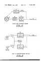
- FIG. 1is a distance diagram indicating typical maximum allowable speeds between Station A and Station B.
- FIG. 2is an illustrative block diagram of an apparatus used to control the speed of a train.
- FIG. 3is a detailed block diagram of a speed and distance sensor shown in FIG. 2.
- FIG. 4is a detailed block diagram of throttle and braking control shown in FIG. 2.
- FIG. 5is a detailed block diagram of a typical operator console shown in FIG. 2.
- FIG. 6is a block diagram of the microcomputer shown in FIG. 2.
- FIG. 7is a flow chart of an operational system as previously shown in FIGS. 2-6.
- FIG. 1 of the drawingsthere is shown on an illustrative linear scale typical miles per hour restrictions between Train Station A and Train Station B as may occur along the track illustrated by reference numeral 10.
- the terms "miles per hour”are abbreviated MPH, and the terms "mile post” ar abbreviated MP.
- MPHmile per hour
- MPmile post
- Such a low speedcould be caused by conditions of the track, busy intersections or other normal or abnormal occurrences.
- the traincould again resume the maximum speed of 49 MPH and maintain that speed until it reaches MP-51.
- the trainmust reduce speed to 40 MPH.
- the trainmust further reduce its speed to 10 MPH and not exceed that speed until it reaches MP-59.
- the 40 MPH restrictionstill applies, therefore the train can resume a speed of 40 MPH and maintain that speed until it reaches MP-75.
- the traincan resume its maximum speed of 49 MPH and maintain that speed until MP-100.
- FIG. 1The above explanation of FIG. 1 and the restrictions along the track 10 as shown in FIG. 1 are simply typical restrictions that an engineer of a train could expect to have to meet in the normal operation of the train.
- a method and apparatusis shown for controlling the speed of a train so that if the engineer ever exceeds the maximum speed limitations, the speed of the train will be automatically reduced or the train will be stopped by the application of the brakes.
- the general concept for controlling the speed of the train between Station A and Station B, or along any other track that would require train orders to implement the particular restrictions,is shown in the general block diagram of FIG. 2.
- Station A(or the station from which the train is leaving) is located a speed and location programmer 12.
- the speed and location programmer 12is used to compile a program that implements the train order or other restrictions and/or conditions into a format that may be used by the microcomputer 14 located on board the train 16.
- the speed and location programmer 12may have a phone link to a central computer 20 that contains other information, such as other trains traveling along the track 10, size, length and weight of the train 16, or other miscellaneous information. All of the information necessary from the central computer 20 is also programmed by the speed and location programmer 12 at Station A.
- the information from the speed and location programmer 12is physically carried by an individual 22 and fed into the microcomputer 14 through speed and location program input 24.
- the physical programmay be in any non-volatile form, such as punched tape, or a magnetic card reading device. These or any other type of non-volatile program that will not lose its memory in case of loss of power may be used for controlling the operation of the microcomputer 14.
- the speed and location program input 24converts speed into distance, and from the train orders programmed therein will feed the correct information into the microcomputer 14.
- the speed between the track 10 and the train 16is continually monitored by a speed and distance sensor 26.
- the speed and distance sensor 26may be of any conventional type, such as a magnetic pickup device that gives a pulse output signal with the frequency of the pulses being dependent upon the rotational velocity of the wheel. Slippage between the wheel and the track does not become a real problem because the amount of slippage is very minimal. Also, procedures as will be explained hereinbelow are included for updating the program depending upon the location along the track. However, if a more positive or true ground speed is desired, many other types of speed and distance sensors, such as the Doppler radar or fifth wheel, may be used to determine true speed between the train 16 and the track.
- microcomputer 14The output from the speed and distance sensor 26 is fed into microcomputer 14 and compared with the input from the speed and location program input 24. If the speed of a train 16 exceeds the maximum speed limitation, microcomputer 14 will give an output to the throttle and/or braking control 28.
- the throttle and/or braking control 28may either reduce the throttle or apply the brakes of the train depending upon the design of the particular system.
- Trip history of the train 16is fed from the microcomputer 14 into a port for extraction of trip history 30 wherein operation of the train 16 versus the program being fed into the microcomputer 14 is recorded in a non-volatile memory.
- the trip historyis extracted from the port for extraction 30. This is particularly important in case of an accident of the train for proving either the safe or unsafe operation of the train 16.
- Various functionsmay be necessary by the operator or engineer of the train 16 as is provided through operator console 32. Operator functions, such as updating the location of the train 16 or moving the train 16 into a siding, is controlled by operator console 32.
- a sealed emergency lockout 34is provided.
- the sealed emergency lockout 34may be a sealed compartment that, if opened by the operator, would be easily recognized as having been opened once the train 16 arrived at the next station.
- the sealed emergency lockout 34would bypass the entire system to release the throttle and/or braking control 28 and return operation of the train 16 to the engineer.
- the speed and location programmer and the central computer 20may both be combined at one location with simply a printout reading device being used at the individual train station for preparing the program (train order) as would be received by the speed and location program input 24.
- the programis fed into the microcomputer 14, the program is checked by the microcomputer 14 in a manner as will be subsequently described, to make sure that the program is valid. Once that is accomplished, control of the train 16 is turned over to the operator through the operator console 32.
- the engineerAfter the train 16 has left Station A or the train yard, the engineer will be signaled that he must press an acknowledgment button upon reaching the first mile post. If the acknowledgment button is not pushed, microcomputer 14 will stop the train 16 by applying the brakes via throttle and/or braking control 28. However, if the engineer pushes the acknowledgment button, the entire system as shown in FIG. 2 will be activated and a maximum speed of the train 16 will be limited as determined by the program (train order).
- the port for extraction of trip history 30may be a very simply check to determine if there have been any speed violations in case of derailment of the train 16. Also, it could be used so that when the train 16 arrived at the next station or train yard, the system as shown in FIG. 2 could be interrogated to determine if there have been any speeding violations. All that is necessary is to have a reading device that would connect to the microcomputer 14 with a non-volatile memory being located in the port for extraction of trip history 30.
- the speed and distance sensor 26is basically a pulse shaper that will give a series of pulse waveform outputs in a type that can be used by the microcomputer 14.
- the speed and distance sensor 26is shown to also include a sensor 36 on the wheel of the train 16, which sensor 36 may be of any conventional type such as a magnetic pickup device. Optical pickups or any other types of sensors could be used to measure the rotation of the wheel, or sensors detecting the speed of the train 16 with respect to the track 10 (such as a Doppler radar), could be used.
- the sensor 36feeds an output signal into a pulse shaping circuit 38 which could consist of a Schmidt trigger.
- the output from the pulse shaping circuit 38is fed into a 15 bit binary-up-counter 40 which output is fed into microcomputer 14.
- a binary-up-counter 40for the pulses, a very convenient means to determine the speed is provided by the number of counts per a given period of time.
- the digital comparator 42which also gives an output signal to the microcomputer 14, simply determines the direction of movement of the train 16, either in the forward or reverse direction.
- the outputs from the digital comparator 42 and the 15 bit binary-up-counter 40are fed into the microcomputer 14 through a normal cable buss connection. Reverse movements of the train 16 are also recorded in the trip history and included to give the exact location of the train.
- a throttle and/or braking control 28which is basically a parallel system that may use the digital output from the microcomputer 14 to either apply the brakes, reduce the throttle, or both, for the train 16 if it exceeds the maximum speed limit.
- the signal from the microcomputer 14is converted to digital analog form by digital-to-analog converters 44 and 46.
- the outputs from the digital-to-analog converters 44 and 46feed through amplifiers 48 and 50, respectively, to drive either a governor or a braking control.
- the reason analog signalsare necessary is because trains presently use analog signals to operate either the throttle or the braking controls. Currently, trains are not operated by digital signals but by analog signals.
- the sealed emergency lockout 34may feed through either amplifier 48 or amplifier 50 upon the braking of the seal thereby preventing an output from either amplifier 48 or 50 to regulate the throttle or apply the brakes.
- a throttle control or a braking controlwould be mutually exclusive of each other.
- a braking controlif the operator of the train 16 exceeded the speed limit, then the train 16 would be stopped thereby emphasizing the violation by the operator.
- control by the engineeris removed only if the engineer exceeds the predetermined speed limit, which violation is recorded in the trip history which is subsequently extracted via the port for extraction of trip history 30.
- the throttle controlBy using the throttle control, the engineer would have full control if he was operating within the predetermined speed limits.
- the braking controlit becomes blatant that the engineer has violated the speed limits when his train is stopped on the tracks.
- FIGS. 5 and 6operation of the microcomputer 14 and operator console 32 is shown in more detail.
- the operator console 32there are actually three ports for feeding information between operator console 32 and microcomputer 14.
- the informationis 8-line binary coded for digital operation.
- Inputs 52 from the microcomputer 14are digital latched outputs that are being transmitted into the operator console 32.
- Outputs 54feed information to the microcomputer 14 from the operator console 32.
- the outputs 54are signals indicating that the operator of the train has performed a certain function as required when he reaches predetermined mile post markers.
- a warning that the operator is to perform these functionsis provided by inputs 52 feeding into lamp drivers 56 to turn ON lamps on the console to indicate to the operator that he must perform certain functions or other information as would normally be given to the operator or engineer.
- Inputs 58are select codes from the microcomputer and do the multiplexing necessary for the signals. Inputs 58 are solely within the microcomputer 14 and operator console 32 and have nothing to do with the operator console.
- the datais entered by the operator by pushing the enter data switch 60.
- the operator of the trainUpon receipt of a system update request 62 on the operator console which is indicated by a lamp, the operator of the train would set in the mile post marker by setting the correct information into thumb wheel switches 64 that give a binary output therefrom.
- the operatorupon receipt of a request for mile post input 68, the operator would push the mile post switch 66 to feed the information from the thumb wheel switches 64 into the microcomputer.
- the mile post switch 66should only be pressed upon the passing of the particular mile post set on the thumb wheel switches 64. This allows the system to be updated and account for any minor variations that could be caused by any of a number of reasons, such as slippage of the wheel on the track.
- the portion of the operator console 32 referred to by reference numeral 70is the contingency section of the operator console. Assume for example that lamp 72 lights up, it would indicate approach to a siding along the track. Switches 74, 76 and 78 allow the operator to select the main line, siding 1 or siding 2, respectively. Lamps 80, 82 and 84 indicate if the correct selection was made. Many other items could be included in the contingency section 70 depending upon the amount of complexity someone would like to design into the system. The program would have to be written so that it will know each time a siding is being approached. Assume for example that the approach to siding lamp 72 lights up, the operator would then indicate through switches 74, 76 or 78 if he was taking the main line, siding 1 or siding 2, respectively. Assume that the operator presses siding 1 switch 76, lamp 82 would light up. If it was the correct selection, lamp 86 would also light up and the operator would acknowledge the correct selection by pushing acknowledgment of correct selection switch 88.
- Warning section 90will tell the operator if he is exceeding the speed limit set by the program by overspeed indicator lamp 92 and by audible alarm 94.
- a driver 96may be necessary. Power for the audible alarm 94 is supplied by one shot 98 that feeds through OR gate 100 to the driver 96.
- the audible alarm 94could have one of two modes. The first mode could be to turn the audible alarm 94 ON through the one shot 98 and to keep the audible alarm 94 ON until a reset is received via inputs 52 from the multiplexer in the microcomputer 14.
- a momentary soundcould be given by the audible alarm 94 very similar to a beep that occurs when a "NO SMOKING" light comes ON on board a commercial passenger airline.
- the momentary soundwould be provided by latch 102 via OR gate 100 and driver 96.
- the microcomputer systemconsists basically of a microprocessor unit 106.
- Components as described in conjunction with the present inventionare standard parts that may be purchased commercially. Particularly integrated circuit components manufactured by Control Logic are typical of the type integrated circuit components that may be used.
- Contained in the microprocessor unit 106is a central processing unit 108 connected to multiplexer 110 and memory input/output control 112.
- the central processing unit 106handles all of the addressing to and from memories and operate the system from the computer program (train order).
- train orderAs can be seen, there are many input and output busses entering and exiting the microprocessing unit 106.
- the bussesprovide the means for transferring information back and forth from memory.
- the data output buss 114takes information from the microprocessing unit 106 and feeds it to device address decoder 116, to a volatile memory 118 and a non-volatile memory 120.
- the non-volatile memory 120may provide the memory for the port for extraction of trip history 30 previously described in conjunction with FIG. 2.
- the volatile memory 118may be erased or altered by a number of conditions, such as loss of power.
- the data output buss 114feeds through the device address decoder 116 to give outputs 58 which correspond to inputs 58 in FIG. 5 of the operator console 32.
- the multiplexer 110also receives information from the input data buss 122.
- Informationsuch as a real time clock 124 and priority interrupt control 126, may provide information to the multiplexer 110 through input data buss 122.
- the real time clock 124works in conjunction with the priority interrupt control 126 so that after a predetermined period of time, the program is interrupted to update and keep track of the real time for the microcomputer 14.
- I/Oinput data buss 122
- I/Oinput data buss
- the multiplexer 110Also feeding into the multiplexer 110 are I/O's 52 via a latched outputs multiplexer 130 which are again selected by I/O's 58. This data is also fed to the volatile memory 118 and non-volatile memory 120.
- the program or train order under which the train is operatedis fed into the microcomputer 14 by means of the speed and location program input 24 that connects through port 132 into the multiplexer 110 and also into the volatile memory 118 and non-volatile memory 120.
- the speed and location program input 24may consist of a number of devices, such as a magnetic card reader.
- the microprocessing unit 106 in volatile memory 118may lose the information stored therein by any of a number of conditions, such as loss of power. However, the non-volatile memory 120 once programmed, stays programmed, and may be used in case of loss of power to restore the volatile memory 118 and reprogram microprocessing unit 106 upon restoring power. To change the information contained in non-volatile memory 120 is very difficult and requires quite a process. An automatic power-up sequence is included in the microprocessing unit 106 to reprogram the information from the non-volatile memory 120 in case of loss of power and restoring power thereto.
- the device address decoder 116is very important to the operation of the microcomputer 14. For any input/output operations to take place, the information to be transferred has its own special code.
- the central processing unit 108selects the code and feeds it to the device address decoder 116.
- the device address decoder 116in turn generates the signal sent to other devices as select lines referred to herein as I/O's 58. Primarily the I/O's 58 are fed to (1) the operator console, (2) the latched outputs multiplexer 130, and (3) the buss ports multiplexer 128.
- Port 132provides a means for extracting the trip history from the microcomputer 6 via the port for extraction of trip history 30. Any particular type of system may be used, such as a magnetic card reader.
- Inputs received into the system through the latched outputs multiplexer 130are maintained until I/O's 58 are fed into the latched outputs multiplexer 130 to change the condition and select another code.
- a real time clock 134(previously designated 124 in conjunction with FIG. 6) operates in conjunction with a program control 136 and a program for extraction of trip history 138 to give an automatic maximum speed regulator and trip history acquisition system (AMSR & THAS) program 140. It is essential to keep track of real time as provided by real time clock 134.
- the program control 136is the main control to operate all subprograms together.
- the program for extraction of trip history 138is the port (previously indicated as port 132) through which the data stored in the non-volatile memory may be obtained to determine the trip history.
- the AMSR & THAS programtakes the data, figures maximum speed, compares with actual speed and sends out a control signal to operate either the throttle or brakes.
- Point A as shown in FIG. 7is where the program is tied together in the flow chart.
- the programis started once the operator pushes the START button 142 (previously referred to in conjunction with FIG. 5 as the enter data switch 60).
- the microcomputergoes through a routing wherein it waits 144 for a check for a speed and distance program 146. If there is a foul-up in the program, then a current system error 148 gives an output to interrupt the program. Assuming there is no problem with the program, the operator of the train will then give an initialize for start 150. However, this is only done after receiving as an input from the check for program 46 and initialize request 152. Also, there is a check for initiate 154, including system update 156, that can interrupt the operation of the train if no response is received.
- a check time for speed and distance update 158is also included that could interrupt operation if no update is received.
- the programis GO (YES)
- an input from the speed and distance binary counter 160which is in the form of pulses, is received by the calculate speed and distance 162.
- the calculate speed and distance 162By knowing either the speed or the distance, the other can be calculated.
- an out-counter reset 164resets the memory that had been storing information from the counter referred to herein as load PS for MD 166.
- the next stepis to calculate the distance traveled since the initial start by using the information received from the calculated speed and distance 162. For convenience in the flow chart, this is referred to as PS 168. If the speed of the train is exceeding that programmed in memory (PS greater than MD), then a cut-speed alarm 170 would be activated and the information would be fed into a store overspeed 172. Also, the control speed 174 would be activated to reduce the speed of the train by either applying the brakes or the throttle. This information is fed into the check for update 176 as indicated by Point A.
- the request for an updateis indicated by out request 178 and the operator may respond by indicating input check point 180.
- Thisprovides for an updating of the microcomputer 14 on a periodic basis. If the engineer or operator is performing his job, an update entered 182 will be indicated. A signal from the update entered 182 is then used to check error 184 and proceed if the amount of error is within given tolerances. If the error is within given tolerances, then a correct error record signal 186 is entered. If the engineer does not perform his duty by giving an update, a check limit of time 188 will so indicate. In other words, the operator of the train has a certain limit of time to respond to the update request. If the request system update 190 has not been timely received, operation of the train will be interrupted.
- a record system update 192is fed into a check distance measurement 194. Then a correct error record signal 196 is generated. Also, if the operator fails to acknowledge, a record operator failure to acknowledge 198 is generated. In the operation of the train, the train should not be out of predetermined bounds upon reaching any particular check point. If the train is out of bounds, then there has been an error possible in the microcomputer 14. If the operator fails to acknowledge the update request, this information is fed into the trip history.
- the trainUpon the completion of the run, or the finishing of the train order programmed therein, the train will wait until the data is extracted by an end-of-run request 206. If the train is not finished, then it will return to the start of the program or check time for S&D update 158. If the trip is over, an end-of-trip indication 208 is given.
Landscapes
- Engineering & Computer Science (AREA)
- Mechanical Engineering (AREA)
- Electric Propulsion And Braking For Vehicles (AREA)
Abstract
Description
Claims (20)
Priority Applications (1)
| Application Number | Priority Date | Filing Date | Title |
|---|---|---|---|
| US05/908,097US4181943A (en) | 1978-05-22 | 1978-05-22 | Speed control device for trains |
Applications Claiming Priority (1)
| Application Number | Priority Date | Filing Date | Title |
|---|---|---|---|
| US05/908,097US4181943A (en) | 1978-05-22 | 1978-05-22 | Speed control device for trains |
Publications (1)
| Publication Number | Publication Date |
|---|---|
| US4181943Atrue US4181943A (en) | 1980-01-01 |
Family
ID=25425175
Family Applications (1)
| Application Number | Title | Priority Date | Filing Date |
|---|---|---|---|
| US05/908,097Expired - LifetimeUS4181943A (en) | 1978-05-22 | 1978-05-22 | Speed control device for trains |
Country Status (1)
| Country | Link |
|---|---|
| US (1) | US4181943A (en) |
Cited By (116)
| Publication number | Priority date | Publication date | Assignee | Title |
|---|---|---|---|---|
| US4428052A (en) | 1981-06-09 | 1984-01-24 | Texas Instruments Incorporated | Navigational aid autopilot |
| EP0114633A1 (en)* | 1983-01-17 | 1984-08-01 | Hitachi, Ltd. | Method for automatic operation of a vehicle |
| US4475159A (en)* | 1982-12-27 | 1984-10-02 | Robert Bosch Gmbh | Method of storing vehicle operating condition parameters |
| US4485444A (en)* | 1980-12-04 | 1984-11-27 | Kabushiki Kaisha Komatsu | Retarder brake automatic control system |
| WO1986000049A1 (en)* | 1984-06-14 | 1986-01-03 | Oy Saab-Valmet Ab | Constant-speed regulator for motor vehicles |
| FR2594246A1 (en)* | 1986-02-07 | 1987-08-14 | Meric Siramy Jean | Sound generator making use of the detonations of an alarm pistol |
| FR2596348A1 (en)* | 1986-03-28 | 1987-10-02 | Magyar Allamvasutak Vezerigazg | DATA PROCESSING AND EDGE INFORMATION SYSTEM FOR RAILWAY SERVICE |
| US4736327A (en)* | 1984-03-05 | 1988-04-05 | Schlumberger Electronics (U.K.) Limited | Data display method and apparatus |
| US4735384A (en)* | 1986-06-04 | 1988-04-05 | Willard Elliott | Apparatus for detecting the distance between a rail vehicle and a remote obstacle on the rail |
| US4752053A (en)* | 1984-06-25 | 1988-06-21 | Dsl Dynamic Sciences Limited | Railway vehicle motion detector |
| US4774669A (en)* | 1986-06-19 | 1988-09-27 | Westinghouse Electric Corp. | Train control having a supervisory monitor providing improved operating safety and better maintenance support |
| US4794548A (en)* | 1986-08-28 | 1988-12-27 | Halliburton Company | Data collection apparatus and train monitoring system |
| US4827438A (en)* | 1987-03-30 | 1989-05-02 | Halliburton Company | Method and apparatus related to simulating train responses to actual train operating data |
| US4835693A (en)* | 1987-02-26 | 1989-05-30 | Utdc Inc. | Brake assurance monitor |
| WO1989005255A1 (en)* | 1987-12-02 | 1989-06-15 | The Secretary Of State For Defence In Her Britanni | Railway network monitoring and control |
| US4843578A (en)* | 1984-10-01 | 1989-06-27 | Wade Ted R | Vehicle speed monitoring and logging means |
| US4853859A (en)* | 1985-01-24 | 1989-08-01 | Shin Caterpillar Mitsubishi Ltd. | Operation data recording system |
| NL8902645A (en)* | 1988-11-22 | 1990-06-18 | Gen Signal Corp | DIGITAL OVERHEAD CONTROLLER FOR USE IN A VITAL PROCESSING SYSTEM. |
| US4988061A (en)* | 1988-03-10 | 1991-01-29 | Thyssen Industries Ag | Method and apparatus for the automatic control of a guided vehicle |
| US5065349A (en)* | 1989-01-11 | 1991-11-12 | Mast-Air Enterprise | Method for and apparatus of monitoring how an operator operates a machine |
| US5072900A (en)* | 1989-03-17 | 1991-12-17 | Aigle Azur Concept | System for the control of the progression of several railway trains in a network |
| US5109343A (en)* | 1990-06-06 | 1992-04-28 | Union Switch & Signal Inc. | Method and apparatus for verification of rail braking distances |
| US5239472A (en)* | 1988-09-28 | 1993-08-24 | Techsearch Incorporated | System for energy conservation on rail vehicles |
| US5440489A (en)* | 1992-02-06 | 1995-08-08 | Westinghouse Brake & Signal Holdings Ltd. | Regulating a railway vehicle |
| US5533695A (en)* | 1994-08-19 | 1996-07-09 | Harmon Industries, Inc. | Incremental train control system |
| US5564657A (en)* | 1994-11-16 | 1996-10-15 | Westinghouse Air Brake Company | Electronically controlled locomotive throttle controller including remote multiple unit throttle control |
| US5740046A (en)* | 1992-08-31 | 1998-04-14 | Abb Daimler Benz Transportation Signal Ab | Method to control in a track traffic system moving units, device for effecting of such control and process for installation of the device |
| US5862062A (en)* | 1996-09-13 | 1999-01-19 | New York Air Brake Corporation | Parallel programming of a plurality of nodes in a communication network |
| WO1999014093A1 (en)* | 1997-09-12 | 1999-03-25 | New York Air Brake Corporation | Method of optimizing train operation and training |
| US6263266B1 (en) | 1998-09-11 | 2001-07-17 | New York Air Brake Corporation | Method of optimizing train operation and training |
| US6332106B1 (en) | 1999-09-16 | 2001-12-18 | New York Air Brake Corporation | Train handling techniques and analysis |
| US6556914B2 (en)* | 2000-04-12 | 2003-04-29 | Daimlerchrysler Rail Systems Gmbh | Semiautomatic control system and method for vehicles |
| US6609049B1 (en) | 2002-07-01 | 2003-08-19 | Quantum Engineering, Inc. | Method and system for automatically activating a warning device on a train |
| US20030236654A1 (en)* | 2002-06-25 | 2003-12-25 | New York Air Brake Corporation | Remote control locomotive simulator |
| US20040006411A1 (en)* | 2002-05-31 | 2004-01-08 | Kane Mark Edward | Method and system for compensating for wheel wear on a train |
| US6680918B1 (en) | 1999-09-07 | 2004-01-20 | New York Air Brake Corporation | Intra-train communication network |
| US6701228B2 (en) | 2002-05-31 | 2004-03-02 | Quantum Engineering, Inc. | Method and system for compensating for wheel wear on a train |
| US20040073342A1 (en)* | 2002-10-10 | 2004-04-15 | Kane Mark Edward | Method and system for ensuring that a train does not pass an improperly configured device |
| US20040093196A1 (en)* | 1999-09-24 | 2004-05-13 | New York Air Brake Corporation | Method of transferring files and analysis of train operational data |
| US6748303B2 (en) | 2002-09-20 | 2004-06-08 | New York Air Brake Corporation | Variable exception reporting |
| US20040181320A1 (en)* | 2002-05-31 | 2004-09-16 | Kane Mark Edward | Method and system for compensating for wheel wear on a train |
| US20040215376A1 (en)* | 2001-10-31 | 2004-10-28 | Hawthorne Michael J | Chain of custody |
| AU2002301645B2 (en)* | 1997-09-12 | 2004-11-25 | New York Air Brake Llc | Method of optimizing train operation and training |
| US20050004722A1 (en)* | 2003-07-02 | 2005-01-06 | Kane Mark Edward | Method and system for automatically locating end of train devices |
| US6845953B2 (en) | 2002-10-10 | 2005-01-25 | Quantum Engineering, Inc. | Method and system for checking track integrity |
| US6853888B2 (en) | 2003-03-21 | 2005-02-08 | Quantum Engineering Inc. | Lifting restrictive signaling in a block |
| US6863246B2 (en) | 2002-12-31 | 2005-03-08 | Quantum Engineering, Inc. | Method and system for automated fault reporting |
| US6865454B2 (en) | 2002-07-02 | 2005-03-08 | Quantum Engineering Inc. | Train control system and method of controlling a train or trains |
| US20050068184A1 (en)* | 2003-09-29 | 2005-03-31 | Kane Mark Edward | Method and system for ensuring that a train operator remains alert during operation of the train |
| US20050110628A1 (en)* | 2003-05-14 | 2005-05-26 | Wabtec Holding Corporation | Operator warning system and method for improving locomotive operator vigilance |
| US6915191B2 (en) | 2003-05-19 | 2005-07-05 | Quantum Engineering, Inc. | Method and system for detecting when an end of train has passed a point |
| US6957131B2 (en) | 2002-11-21 | 2005-10-18 | Quantum Engineering, Inc. | Positive signal comparator and method |
| US20050246075A1 (en)* | 2002-08-07 | 2005-11-03 | New York Air Brake Corporation | Advanced Simulation capture and reporting tools |
| US20060076826A1 (en)* | 2004-10-12 | 2006-04-13 | Kane Mark E | Failsafe electronic braking system for trains |
| US7073753B2 (en) | 1996-09-13 | 2006-07-11 | New York Airbrake Corporation | Integrated train control |
| US7096171B2 (en) | 2002-08-07 | 2006-08-22 | New York Air Brake Corporation | Train simulator and playback station |
| US7142982B2 (en) | 2004-09-13 | 2006-11-28 | Quantum Engineering, Inc. | System and method for determining relative differential positioning system measurement solutions |
| US20070219683A1 (en)* | 2006-03-20 | 2007-09-20 | Wolfgang Daum | System and Method for Optimized Fuel Efficiency and Emission Output of a Diesel Powered System |
| US20070219682A1 (en)* | 2006-03-20 | 2007-09-20 | Ajith Kumar | Method, system and computer software code for trip optimization with train/track database augmentation |
| US20070219680A1 (en)* | 2006-03-20 | 2007-09-20 | Kumar Ajith K | Trip optimization system and method for a train |
| US20070225878A1 (en)* | 2006-03-20 | 2007-09-27 | Kumar Ajith K | Trip optimization system and method for a train |
| US20070233364A1 (en)* | 2006-03-20 | 2007-10-04 | Ajith Kuttannair Kumar | Trip Optimization System and Method for a Vehicle |
| US20070250225A1 (en)* | 2006-04-24 | 2007-10-25 | Nickles Stephen K | Method of forecasting train speed |
| US20080033605A1 (en)* | 2006-03-20 | 2008-02-07 | Wolfgang Daum | System and method for optimizing parameters of multiple rail vehicles operating over multiple intersecting railroad networks |
| US20080099633A1 (en)* | 2006-10-31 | 2008-05-01 | Quantum Engineering, Inc. | Method and apparatus for sounding horn on a train |
| US20080128562A1 (en)* | 2006-12-01 | 2008-06-05 | Ajith Kuttannair Kumar | Method and apparatus for limiting in-train forces of a railroad train |
| US20080154452A1 (en)* | 2006-03-20 | 2008-06-26 | Kevin Kapp | System and method for predicting a vehicle route using a route network database |
| US20080161984A1 (en)* | 2006-12-01 | 2008-07-03 | Kaitlyn Hrdlicka | System and method for determining a mismatch between a model for a powered system and the actual behavior of the powered system |
| US20080167766A1 (en)* | 2006-03-20 | 2008-07-10 | Saravanan Thiyagarajan | Method and Computer Software Code for Optimizing a Range When an Operating Mode of a Powered System is Encountered During a Mission |
| US20080167767A1 (en)* | 2006-03-20 | 2008-07-10 | Brooks James D | Method and Computer Software Code for Determining When to Permit a Speed Control System to Control a Powered System |
| US20080183490A1 (en)* | 2006-03-20 | 2008-07-31 | Martin William P | Method and computer software code for implementing a revised mission plan for a powered system |
| US20080201028A1 (en)* | 2006-03-20 | 2008-08-21 | Brooks James D | Method and computer software code for uncoupling power control of a distributed powered system from coupled power settings |
| US20080201019A1 (en)* | 2006-03-20 | 2008-08-21 | Ajith Kuttannair Kumar | Method and computer software code for optimized fuel efficiency emission output and mission performance of a powered system |
| US20080208401A1 (en)* | 2006-03-20 | 2008-08-28 | Ajith Kuttannair Kumar | System, method, and computer software code for insuring continuous flow of information to an operator of a powered system |
| US20080306641A1 (en)* | 2006-10-06 | 2008-12-11 | New York Air Brake Corporation | Human Machine Interface for Speed and Location Control with Braking Distance Display |
| US20090043435A1 (en)* | 2007-08-07 | 2009-02-12 | Quantum Engineering, Inc. | Methods and systems for making a gps signal vital |
| US20090058624A1 (en)* | 2007-08-28 | 2009-03-05 | Quantum Engineering, Inc. | Cognitive alerter |
| US20090125170A1 (en)* | 2007-04-25 | 2009-05-14 | Joseph Forrest Noffsinger | System and method for optimizing a braking schedule of a powered system traveling along a route |
| US20090187291A1 (en)* | 2006-03-20 | 2009-07-23 | Wolfgang Daum | System, method, and computer software code for providing real time optimization of a mission plan for a powered system |
| US20090234523A1 (en)* | 2008-03-13 | 2009-09-17 | Vishram Vinayak Nandedkar | System and method for determining a quality of a location estimation of a powered system |
| US20090254239A1 (en)* | 2006-03-20 | 2009-10-08 | Wolfgang Daum | System, method, and computer software code for detecting a physical defect along a mission route |
| US20090255329A1 (en)* | 2008-04-14 | 2009-10-15 | Wabtec Holding Corp. | Method and System for Determining Brake Shoe Effectiveness |
| US20100023190A1 (en)* | 2006-03-20 | 2010-01-28 | General Electric Company | Trip optimizer method, system and computer software code for operating a railroad train to minimize wheel and track wear |
| AU2004243288B2 (en)* | 2003-05-22 | 2010-02-18 | Ge Global Sourcing Llc | Method and system for controlling locomotives |
| US20100168942A1 (en)* | 2008-12-29 | 2010-07-01 | Joseph Forrest Noffsinger | System And Method For Optimizing A Path For A Marine Vessel Through A Waterway |
| US20100213321A1 (en)* | 2009-02-24 | 2010-08-26 | Quantum Engineering, Inc. | Method and systems for end of train force reporting |
| US20100262321A1 (en)* | 2006-03-20 | 2010-10-14 | Wolfgang Daum | System, Method and Computer Software Code for Optimizing Train Operations Considering Rail Car Parameters |
| US20110060486A1 (en)* | 2009-09-09 | 2011-03-10 | General Electronics Corporation | Control system and method for remotely isolating powered units in a rail vehicle system |
| US20110148748A1 (en)* | 2009-12-17 | 2011-06-23 | Taewook Lee | Liquid crystal display and method of updating software |
| US8290645B2 (en) | 2006-03-20 | 2012-10-16 | General Electric Company | Method and computer software code for determining a mission plan for a powered system when a desired mission parameter appears unobtainable |
| US8295993B2 (en) | 2006-03-20 | 2012-10-23 | General Electric Company | System, method, and computer software code for optimizing speed regulation of a remotely controlled powered system |
| US8398405B2 (en) | 2006-03-20 | 2013-03-19 | General Electric Company | System, method, and computer software code for instructing an operator to control a powered system having an autonomous controller |
| US8509970B2 (en) | 2009-06-30 | 2013-08-13 | Invensys Rail Corporation | Vital speed profile to control a train moving along a track |
| US8565946B2 (en) | 2011-07-01 | 2013-10-22 | General Electric Company | System and method for vehicle control |
| US8700237B1 (en) | 2012-12-11 | 2014-04-15 | Electro-Motive Diesel | System and method for communicating critical and noncritical data in a consist |
| US8751073B2 (en) | 2006-03-20 | 2014-06-10 | General Electric Company | Method and apparatus for optimizing a train trip using signal information |
| US8924049B2 (en) | 2003-01-06 | 2014-12-30 | General Electric Company | System and method for controlling movement of vehicles |
| US8965604B2 (en) | 2008-03-13 | 2015-02-24 | General Electric Company | System and method for determining a quality value of a location estimation of a powered system |
| US8998617B2 (en) | 2006-03-20 | 2015-04-07 | General Electric Company | System, method, and computer software code for instructing an operator to control a powered system having an autonomous controller |
| US9043044B2 (en) | 2012-12-11 | 2015-05-26 | Electro-Motive Diesel, Inc. | System and method for communicating data in a consist |
| US9049561B2 (en) | 2012-12-11 | 2015-06-02 | Electro-Motive Diesel, Inc. | System and method for distributing track information in a consist |
| US9079589B2 (en) | 2009-09-09 | 2015-07-14 | General Electric Company | Control system and method for remotely isolating powered units in a vehicle system |
| US9120493B2 (en) | 2007-04-30 | 2015-09-01 | General Electric Company | Method and apparatus for determining track features and controlling a railroad train responsive thereto |
| US9156477B2 (en) | 2006-03-20 | 2015-10-13 | General Electric Company | Control system and method for remotely isolating powered units in a vehicle system |
| US9201409B2 (en) | 2006-03-20 | 2015-12-01 | General Electric Company | Fuel management system and method |
| US9469310B2 (en)* | 2012-10-18 | 2016-10-18 | Wabtec Holding Corp. | System, apparatus, and method for automatically controlling a locomotive |
| US9527518B2 (en) | 2006-03-20 | 2016-12-27 | General Electric Company | System, method and computer software code for controlling a powered system and operational information used in a mission by the powered system |
| US9580090B2 (en) | 2006-12-01 | 2017-02-28 | General Electric Company | System, method, and computer readable medium for improving the handling of a powered system traveling along a route |
| US9669851B2 (en) | 2012-11-21 | 2017-06-06 | General Electric Company | Route examination system and method |
| US9682716B2 (en) | 2012-11-21 | 2017-06-20 | General Electric Company | Route examining system and method |
| US9689681B2 (en) | 2014-08-12 | 2017-06-27 | General Electric Company | System and method for vehicle operation |
| US9702715B2 (en) | 2012-10-17 | 2017-07-11 | General Electric Company | Distributed energy management system and method for a vehicle system |
| US9834237B2 (en) | 2012-11-21 | 2017-12-05 | General Electric Company | Route examining system and method |
| US10308265B2 (en) | 2006-03-20 | 2019-06-04 | Ge Global Sourcing Llc | Vehicle control system and method |
| US10569792B2 (en) | 2006-03-20 | 2020-02-25 | General Electric Company | Vehicle control system and method |
| US11208125B2 (en)* | 2016-08-08 | 2021-12-28 | Transportation Ip Holdings, Llc | Vehicle control system |
Citations (10)
| Publication number | Priority date | Publication date | Assignee | Title |
|---|---|---|---|---|
| US3582894A (en)* | 1968-05-20 | 1971-06-01 | Westinghouse Electric Corp | Coded signal transmission system |
| US3604905A (en)* | 1967-10-23 | 1971-09-14 | Secheron Atel | Electronic device for the automatic control of a railway train |
| US3639753A (en)* | 1969-09-15 | 1972-02-01 | Gen Signal Corp | System for governing the speed of railway vehicles |
| US3655962A (en)* | 1969-04-01 | 1972-04-11 | Melpar Inc | Digital automatic speed control for railway vehicles |
| US3696356A (en)* | 1971-06-17 | 1972-10-03 | Westinghouse Air Brake Co | Acknowledging circuit arrangement |
| US3825672A (en)* | 1970-05-13 | 1974-07-23 | J Malon | Device emitting or receiving electrical signals resulting from the movement of a vehicle along the device |
| US3845289A (en)* | 1972-07-18 | 1974-10-29 | Avon Inc | Method and apparatus employing automatic route control system |
| US3885228A (en)* | 1973-06-05 | 1975-05-20 | Martin J Katz | Fail-safe electronic encoder for selectively operating railway signal indicator |
| US4056287A (en)* | 1976-01-20 | 1977-11-01 | Wabco Westinghouse Gmbh | Circuit arrangement for producing a digital speed signal corresponding to the angular velocity of a wheel from the half cycle duration of the sinusoidal waveform generated by the wheel |
| US4107253A (en)* | 1976-12-01 | 1978-08-15 | U.S. Philips Corporation | Safety and test device in a railway signalling system |
- 1978
- 1978-05-22USUS05/908,097patent/US4181943A/ennot_activeExpired - Lifetime
Patent Citations (10)
| Publication number | Priority date | Publication date | Assignee | Title |
|---|---|---|---|---|
| US3604905A (en)* | 1967-10-23 | 1971-09-14 | Secheron Atel | Electronic device for the automatic control of a railway train |
| US3582894A (en)* | 1968-05-20 | 1971-06-01 | Westinghouse Electric Corp | Coded signal transmission system |
| US3655962A (en)* | 1969-04-01 | 1972-04-11 | Melpar Inc | Digital automatic speed control for railway vehicles |
| US3639753A (en)* | 1969-09-15 | 1972-02-01 | Gen Signal Corp | System for governing the speed of railway vehicles |
| US3825672A (en)* | 1970-05-13 | 1974-07-23 | J Malon | Device emitting or receiving electrical signals resulting from the movement of a vehicle along the device |
| US3696356A (en)* | 1971-06-17 | 1972-10-03 | Westinghouse Air Brake Co | Acknowledging circuit arrangement |
| US3845289A (en)* | 1972-07-18 | 1974-10-29 | Avon Inc | Method and apparatus employing automatic route control system |
| US3885228A (en)* | 1973-06-05 | 1975-05-20 | Martin J Katz | Fail-safe electronic encoder for selectively operating railway signal indicator |
| US4056287A (en)* | 1976-01-20 | 1977-11-01 | Wabco Westinghouse Gmbh | Circuit arrangement for producing a digital speed signal corresponding to the angular velocity of a wheel from the half cycle duration of the sinusoidal waveform generated by the wheel |
| US4107253A (en)* | 1976-12-01 | 1978-08-15 | U.S. Philips Corporation | Safety and test device in a railway signalling system |
Cited By (190)
| Publication number | Priority date | Publication date | Assignee | Title |
|---|---|---|---|---|
| US4485444A (en)* | 1980-12-04 | 1984-11-27 | Kabushiki Kaisha Komatsu | Retarder brake automatic control system |
| US4428052A (en) | 1981-06-09 | 1984-01-24 | Texas Instruments Incorporated | Navigational aid autopilot |
| US4475159A (en)* | 1982-12-27 | 1984-10-02 | Robert Bosch Gmbh | Method of storing vehicle operating condition parameters |
| EP0257662A3 (en)* | 1983-01-17 | 1988-05-18 | Hitachi, Ltd. | Method for automatically controlling a vehicle |
| US4617627A (en)* | 1983-01-17 | 1986-10-14 | Hitachi, Ltd. | Method for automatic operation of a vehicle |
| EP0114633A1 (en)* | 1983-01-17 | 1984-08-01 | Hitachi, Ltd. | Method for automatic operation of a vehicle |
| US4736327A (en)* | 1984-03-05 | 1988-04-05 | Schlumberger Electronics (U.K.) Limited | Data display method and apparatus |
| WO1986000049A1 (en)* | 1984-06-14 | 1986-01-03 | Oy Saab-Valmet Ab | Constant-speed regulator for motor vehicles |
| US4752053A (en)* | 1984-06-25 | 1988-06-21 | Dsl Dynamic Sciences Limited | Railway vehicle motion detector |
| US4843578A (en)* | 1984-10-01 | 1989-06-27 | Wade Ted R | Vehicle speed monitoring and logging means |
| US4853859A (en)* | 1985-01-24 | 1989-08-01 | Shin Caterpillar Mitsubishi Ltd. | Operation data recording system |
| FR2594246A1 (en)* | 1986-02-07 | 1987-08-14 | Meric Siramy Jean | Sound generator making use of the detonations of an alarm pistol |
| FR2596348A1 (en)* | 1986-03-28 | 1987-10-02 | Magyar Allamvasutak Vezerigazg | DATA PROCESSING AND EDGE INFORMATION SYSTEM FOR RAILWAY SERVICE |
| US4735384A (en)* | 1986-06-04 | 1988-04-05 | Willard Elliott | Apparatus for detecting the distance between a rail vehicle and a remote obstacle on the rail |
| US4774669A (en)* | 1986-06-19 | 1988-09-27 | Westinghouse Electric Corp. | Train control having a supervisory monitor providing improved operating safety and better maintenance support |
| US4794548A (en)* | 1986-08-28 | 1988-12-27 | Halliburton Company | Data collection apparatus and train monitoring system |
| US4835693A (en)* | 1987-02-26 | 1989-05-30 | Utdc Inc. | Brake assurance monitor |
| US4827438A (en)* | 1987-03-30 | 1989-05-02 | Halliburton Company | Method and apparatus related to simulating train responses to actual train operating data |
| WO1989005255A1 (en)* | 1987-12-02 | 1989-06-15 | The Secretary Of State For Defence In Her Britanni | Railway network monitoring and control |
| GB2230885A (en)* | 1987-12-02 | 1990-10-31 | Secr Defence | Railway network monitoring and control |
| GB2230885B (en)* | 1987-12-02 | 1991-08-07 | Secr Defence | Railway network monitoring and control |
| US4988061A (en)* | 1988-03-10 | 1991-01-29 | Thyssen Industries Ag | Method and apparatus for the automatic control of a guided vehicle |
| US5239472A (en)* | 1988-09-28 | 1993-08-24 | Techsearch Incorporated | System for energy conservation on rail vehicles |
| NL8902645A (en)* | 1988-11-22 | 1990-06-18 | Gen Signal Corp | DIGITAL OVERHEAD CONTROLLER FOR USE IN A VITAL PROCESSING SYSTEM. |
| US4956779A (en)* | 1988-11-22 | 1990-09-11 | General Signal Corporation | Digital overspeed controller for use in a vital processing system |
| US5065349A (en)* | 1989-01-11 | 1991-11-12 | Mast-Air Enterprise | Method for and apparatus of monitoring how an operator operates a machine |
| US5072900A (en)* | 1989-03-17 | 1991-12-17 | Aigle Azur Concept | System for the control of the progression of several railway trains in a network |
| US5109343A (en)* | 1990-06-06 | 1992-04-28 | Union Switch & Signal Inc. | Method and apparatus for verification of rail braking distances |
| US5440489A (en)* | 1992-02-06 | 1995-08-08 | Westinghouse Brake & Signal Holdings Ltd. | Regulating a railway vehicle |
| US5740046A (en)* | 1992-08-31 | 1998-04-14 | Abb Daimler Benz Transportation Signal Ab | Method to control in a track traffic system moving units, device for effecting of such control and process for installation of the device |
| US5533695A (en)* | 1994-08-19 | 1996-07-09 | Harmon Industries, Inc. | Incremental train control system |
| US5564657A (en)* | 1994-11-16 | 1996-10-15 | Westinghouse Air Brake Company | Electronically controlled locomotive throttle controller including remote multiple unit throttle control |
| US5862062A (en)* | 1996-09-13 | 1999-01-19 | New York Air Brake Corporation | Parallel programming of a plurality of nodes in a communication network |
| US7073753B2 (en) | 1996-09-13 | 2006-07-11 | New York Airbrake Corporation | Integrated train control |
| US6144901A (en)* | 1997-09-12 | 2000-11-07 | New York Air Brake Corporation | Method of optimizing train operation and training |
| US6587764B2 (en) | 1997-09-12 | 2003-07-01 | New York Air Brake Corporation | Method of optimizing train operation and training |
| WO1999014093A1 (en)* | 1997-09-12 | 1999-03-25 | New York Air Brake Corporation | Method of optimizing train operation and training |
| AU2002301645B2 (en)* | 1997-09-12 | 2004-11-25 | New York Air Brake Llc | Method of optimizing train operation and training |
| US6263266B1 (en) | 1998-09-11 | 2001-07-17 | New York Air Brake Corporation | Method of optimizing train operation and training |
| US6622068B2 (en) | 1998-09-11 | 2003-09-16 | New York Air Brake Corporation | Method of optimizing train operation and training |
| US6680918B1 (en) | 1999-09-07 | 2004-01-20 | New York Air Brake Corporation | Intra-train communication network |
| US6332106B1 (en) | 1999-09-16 | 2001-12-18 | New York Air Brake Corporation | Train handling techniques and analysis |
| US20040093196A1 (en)* | 1999-09-24 | 2004-05-13 | New York Air Brake Corporation | Method of transferring files and analysis of train operational data |
| US7263475B2 (en) | 1999-09-24 | 2007-08-28 | New York Air Brake Corporation | Method of transferring files and analysis of train operational data |
| US7188341B1 (en) | 1999-09-24 | 2007-03-06 | New York Air Brake Corporation | Method of transferring files and analysis of train operational data |
| US6556914B2 (en)* | 2000-04-12 | 2003-04-29 | Daimlerchrysler Rail Systems Gmbh | Semiautomatic control system and method for vehicles |
| AU2002301645C1 (en)* | 2001-03-15 | 2004-12-02 | New York Air Brake Llc | Method of optimizing train operation and training |
| US20040215376A1 (en)* | 2001-10-31 | 2004-10-28 | Hawthorne Michael J | Chain of custody |
| US7188009B2 (en)* | 2001-10-31 | 2007-03-06 | New York Air Brake Corporation | Chain of custody |
| US7593795B2 (en) | 2002-05-31 | 2009-09-22 | Quantum Engineering, Inc. | Method and system for compensating for wheel wear on a train |
| US20040181320A1 (en)* | 2002-05-31 | 2004-09-16 | Kane Mark Edward | Method and system for compensating for wheel wear on a train |
| US6701228B2 (en) | 2002-05-31 | 2004-03-02 | Quantum Engineering, Inc. | Method and system for compensating for wheel wear on a train |
| US20040006411A1 (en)* | 2002-05-31 | 2004-01-08 | Kane Mark Edward | Method and system for compensating for wheel wear on a train |
| US7283897B2 (en) | 2002-05-31 | 2007-10-16 | Quantum Engineering, Inc. | Method and system for compensating for wheel wear on a train |
| US6970774B2 (en) | 2002-05-31 | 2005-11-29 | Quantum Engineering, Inc. | Method and system for compensating for wheel wear on a train |
| US20070112482A1 (en)* | 2002-05-31 | 2007-05-17 | Quantum Engineering, Inc. | Method and system for compensating for wheel wear on a train |
| US20070095988A1 (en)* | 2002-05-31 | 2007-05-03 | Quantum Engineering, Inc. | Method and System for Compensating for Wheel Wear on a Train |
| US7143017B2 (en) | 2002-06-25 | 2006-11-28 | New York Air Brake Corporation | Remote control locomotive simulator |
| US20030236654A1 (en)* | 2002-06-25 | 2003-12-25 | New York Air Brake Corporation | Remote control locomotive simulator |
| US6824110B2 (en) | 2002-07-01 | 2004-11-30 | Quantum Engineering, Inc. | Method and system for automatically activating a warning device on a train |
| US6609049B1 (en) | 2002-07-01 | 2003-08-19 | Quantum Engineering, Inc. | Method and system for automatically activating a warning device on a train |
| US20040015276A1 (en)* | 2002-07-01 | 2004-01-22 | Kane Mark Edward | Method and system for automatically activating a warning device on a train |
| US20050085961A1 (en)* | 2002-07-02 | 2005-04-21 | Kane Mark E. | Train control system and method of controlling a train or trains |
| US7200471B2 (en) | 2002-07-02 | 2007-04-03 | Quantum Engineering, Inc. | Train control system and method of controlling a train or trains |
| US6865454B2 (en) | 2002-07-02 | 2005-03-08 | Quantum Engineering Inc. | Train control system and method of controlling a train or trains |
| US7139646B2 (en) | 2002-07-02 | 2006-11-21 | Quantum Engineering, Inc. | Train control system and method of controlling a train or trains |
| US6978195B2 (en) | 2002-07-02 | 2005-12-20 | Quantum Engineering, Inc. | Train control system and method of controlling a train or trains |
| US20060253234A1 (en)* | 2002-07-02 | 2006-11-09 | Kane Mark E | Train control system and method of controlling a train or trains |
| US20060041341A1 (en)* | 2002-07-02 | 2006-02-23 | Kane Mark E | Train control system and method of controlling a train or trains |
| US20060052913A1 (en)* | 2002-07-02 | 2006-03-09 | Kane Mark E | Train control system and method of controlling a train or trains |
| US7079926B2 (en) | 2002-07-02 | 2006-07-18 | Quantum Engineering, Inc. | Train control system and method of controlling a train or trains |
| US7647141B2 (en) | 2002-08-07 | 2010-01-12 | New York Air Brake Corporation | Advanced simulation capture and reporting tools |
| US20050246075A1 (en)* | 2002-08-07 | 2005-11-03 | New York Air Brake Corporation | Advanced Simulation capture and reporting tools |
| US7096171B2 (en) | 2002-08-07 | 2006-08-22 | New York Air Brake Corporation | Train simulator and playback station |
| US6748303B2 (en) | 2002-09-20 | 2004-06-08 | New York Air Brake Corporation | Variable exception reporting |
| US20060080009A1 (en)* | 2002-10-10 | 2006-04-13 | Kane Mark E | Method and system for ensuring that a train does not pass an improperly configured device |
| US6996461B2 (en) | 2002-10-10 | 2006-02-07 | Quantum Engineering, Inc. | Method and system for ensuring that a train does not pass an improperly configured device |
| US20040073342A1 (en)* | 2002-10-10 | 2004-04-15 | Kane Mark Edward | Method and system for ensuring that a train does not pass an improperly configured device |
| US6845953B2 (en) | 2002-10-10 | 2005-01-25 | Quantum Engineering, Inc. | Method and system for checking track integrity |
| US7236860B2 (en) | 2002-10-10 | 2007-06-26 | Quantum Engineering, Inc. | Method and system for ensuring that a train does not pass an improperly configured device |
| US20050061923A1 (en)* | 2002-10-10 | 2005-03-24 | Kane Mark Edward | Method and system for checking track integrity |
| US7036774B2 (en) | 2002-10-10 | 2006-05-02 | Quantum Engineering, Inc. | Method and system for checking track integrity |
| US6957131B2 (en) | 2002-11-21 | 2005-10-18 | Quantum Engineering, Inc. | Positive signal comparator and method |
| US6863246B2 (en) | 2002-12-31 | 2005-03-08 | Quantum Engineering, Inc. | Method and system for automated fault reporting |
| US8924049B2 (en) | 2003-01-06 | 2014-12-30 | General Electric Company | System and method for controlling movement of vehicles |
| US20050159860A1 (en)* | 2003-03-21 | 2005-07-21 | Kane Mark E. | Lifting restrictive signaling in a block |
| US7092800B2 (en) | 2003-03-21 | 2006-08-15 | Quantum Engineering, Inc. | Lifting restrictive signaling in a block |
| US6853888B2 (en) | 2003-03-21 | 2005-02-08 | Quantum Engineering Inc. | Lifting restrictive signaling in a block |
| US20050110628A1 (en)* | 2003-05-14 | 2005-05-26 | Wabtec Holding Corporation | Operator warning system and method for improving locomotive operator vigilance |
| US7398140B2 (en) | 2003-05-14 | 2008-07-08 | Wabtec Holding Corporation | Operator warning system and method for improving locomotive operator vigilance |
| US6915191B2 (en) | 2003-05-19 | 2005-07-05 | Quantum Engineering, Inc. | Method and system for detecting when an end of train has passed a point |
| AU2004243288B2 (en)* | 2003-05-22 | 2010-02-18 | Ge Global Sourcing Llc | Method and system for controlling locomotives |
| US20100253548A1 (en)* | 2003-07-02 | 2010-10-07 | Invensys Rail Corporation | Method and system for automatically locating end of train devices |
| US7742850B2 (en) | 2003-07-02 | 2010-06-22 | Invensys Rail Corporation | Method and system for automatically locating end of train devices |
| US20060184290A1 (en)* | 2003-07-02 | 2006-08-17 | Quantum Engineering Inc. | Method and system for automatically locating end of train devices |
| US20050004722A1 (en)* | 2003-07-02 | 2005-01-06 | Kane Mark Edward | Method and system for automatically locating end of train devices |
| US7096096B2 (en) | 2003-07-02 | 2006-08-22 | Quantum Engineering Inc. | Method and system for automatically locating end of train devices |
| US20090093920A1 (en)* | 2003-07-02 | 2009-04-09 | Quantum Engineering, Inc. | Method and system for automatically locating end of train devices |
| US7467032B2 (en) | 2003-07-02 | 2008-12-16 | Quantum Engineering, Inc. | Method and system for automatically locating end of train devices |
| US6903658B2 (en) | 2003-09-29 | 2005-06-07 | Quantum Engineering, Inc. | Method and system for ensuring that a train operator remains alert during operation of the train |
| US20050068184A1 (en)* | 2003-09-29 | 2005-03-31 | Kane Mark Edward | Method and system for ensuring that a train operator remains alert during operation of the train |
| US7142982B2 (en) | 2004-09-13 | 2006-11-28 | Quantum Engineering, Inc. | System and method for determining relative differential positioning system measurement solutions |
| US20060076826A1 (en)* | 2004-10-12 | 2006-04-13 | Kane Mark E | Failsafe electronic braking system for trains |
| US7722134B2 (en) | 2004-10-12 | 2010-05-25 | Invensys Rail Corporation | Failsafe electronic braking system for trains |
| US20070219682A1 (en)* | 2006-03-20 | 2007-09-20 | Ajith Kumar | Method, system and computer software code for trip optimization with train/track database augmentation |
| US8370007B2 (en) | 2006-03-20 | 2013-02-05 | General Electric Company | Method and computer software code for determining when to permit a speed control system to control a powered system |
| US20080154452A1 (en)* | 2006-03-20 | 2008-06-26 | Kevin Kapp | System and method for predicting a vehicle route using a route network database |
| US20080167766A1 (en)* | 2006-03-20 | 2008-07-10 | Saravanan Thiyagarajan | Method and Computer Software Code for Optimizing a Range When an Operating Mode of a Powered System is Encountered During a Mission |
| US20080167767A1 (en)* | 2006-03-20 | 2008-07-10 | Brooks James D | Method and Computer Software Code for Determining When to Permit a Speed Control System to Control a Powered System |
| US20080183490A1 (en)* | 2006-03-20 | 2008-07-31 | Martin William P | Method and computer software code for implementing a revised mission plan for a powered system |
| US20080201028A1 (en)* | 2006-03-20 | 2008-08-21 | Brooks James D | Method and computer software code for uncoupling power control of a distributed powered system from coupled power settings |
| US20080201019A1 (en)* | 2006-03-20 | 2008-08-21 | Ajith Kuttannair Kumar | Method and computer software code for optimized fuel efficiency emission output and mission performance of a powered system |
| US20080208401A1 (en)* | 2006-03-20 | 2008-08-28 | Ajith Kuttannair Kumar | System, method, and computer software code for insuring continuous flow of information to an operator of a powered system |
| US10569792B2 (en) | 2006-03-20 | 2020-02-25 | General Electric Company | Vehicle control system and method |
| US10308265B2 (en) | 2006-03-20 | 2019-06-04 | Ge Global Sourcing Llc | Vehicle control system and method |
| US9733625B2 (en) | 2006-03-20 | 2017-08-15 | General Electric Company | Trip optimization system and method for a train |
| US9527518B2 (en) | 2006-03-20 | 2016-12-27 | General Electric Company | System, method and computer software code for controlling a powered system and operational information used in a mission by the powered system |
| US9266542B2 (en) | 2006-03-20 | 2016-02-23 | General Electric Company | System and method for optimized fuel efficiency and emission output of a diesel powered system |
| US9233696B2 (en) | 2006-03-20 | 2016-01-12 | General Electric Company | Trip optimizer method, system and computer software code for operating a railroad train to minimize wheel and track wear |
| US9201409B2 (en) | 2006-03-20 | 2015-12-01 | General Electric Company | Fuel management system and method |
| US20090187291A1 (en)* | 2006-03-20 | 2009-07-23 | Wolfgang Daum | System, method, and computer software code for providing real time optimization of a mission plan for a powered system |
| US9156477B2 (en) | 2006-03-20 | 2015-10-13 | General Electric Company | Control system and method for remotely isolating powered units in a vehicle system |
| US20080033605A1 (en)* | 2006-03-20 | 2008-02-07 | Wolfgang Daum | System and method for optimizing parameters of multiple rail vehicles operating over multiple intersecting railroad networks |
| US20090254239A1 (en)* | 2006-03-20 | 2009-10-08 | Wolfgang Daum | System, method, and computer software code for detecting a physical defect along a mission route |
| US8998617B2 (en) | 2006-03-20 | 2015-04-07 | General Electric Company | System, method, and computer software code for instructing an operator to control a powered system having an autonomous controller |
| US20070219683A1 (en)* | 2006-03-20 | 2007-09-20 | Wolfgang Daum | System and Method for Optimized Fuel Efficiency and Emission Output of a Diesel Powered System |
| US20100023190A1 (en)* | 2006-03-20 | 2010-01-28 | General Electric Company | Trip optimizer method, system and computer software code for operating a railroad train to minimize wheel and track wear |
| US20070233364A1 (en)* | 2006-03-20 | 2007-10-04 | Ajith Kuttannair Kumar | Trip Optimization System and Method for a Vehicle |
| US20070233335A1 (en)* | 2006-03-20 | 2007-10-04 | Ajith Kuttannair Kumar | Method and apparatus for optimizing railroad train operation for a train including multiple distributed-power locomotives |
| US20070225878A1 (en)* | 2006-03-20 | 2007-09-27 | Kumar Ajith K | Trip optimization system and method for a train |
| US8903573B2 (en) | 2006-03-20 | 2014-12-02 | General Electric Company | Method and computer software code for determining a mission plan for a powered system when a desired mission parameter appears unobtainable |
| US8788135B2 (en) | 2006-03-20 | 2014-07-22 | General Electric Company | System, method, and computer software code for providing real time optimization of a mission plan for a powered system |
| US8768543B2 (en) | 2006-03-20 | 2014-07-01 | General Electric Company | Method, system and computer software code for trip optimization with train/track database augmentation |
| US20070219680A1 (en)* | 2006-03-20 | 2007-09-20 | Kumar Ajith K | Trip optimization system and method for a train |
| US20100262321A1 (en)* | 2006-03-20 | 2010-10-14 | Wolfgang Daum | System, Method and Computer Software Code for Optimizing Train Operations Considering Rail Car Parameters |
| US8751073B2 (en) | 2006-03-20 | 2014-06-10 | General Electric Company | Method and apparatus for optimizing a train trip using signal information |
| US8725326B2 (en) | 2006-03-20 | 2014-05-13 | General Electric Company | System and method for predicting a vehicle route using a route network database |
| US7974774B2 (en) | 2006-03-20 | 2011-07-05 | General Electric Company | Trip optimization system and method for a vehicle |
| US8630757B2 (en) | 2006-03-20 | 2014-01-14 | General Electric Company | System and method for optimizing parameters of multiple rail vehicles operating over multiple intersecting railroad networks |
| US8126601B2 (en) | 2006-03-20 | 2012-02-28 | General Electric Company | System and method for predicting a vehicle route using a route network database |
| US8473127B2 (en) | 2006-03-20 | 2013-06-25 | General Electric Company | System, method and computer software code for optimizing train operations considering rail car parameters |
| US8401720B2 (en) | 2006-03-20 | 2013-03-19 | General Electric Company | System, method, and computer software code for detecting a physical defect along a mission route |
| US8398405B2 (en) | 2006-03-20 | 2013-03-19 | General Electric Company | System, method, and computer software code for instructing an operator to control a powered system having an autonomous controller |
| US8295993B2 (en) | 2006-03-20 | 2012-10-23 | General Electric Company | System, method, and computer software code for optimizing speed regulation of a remotely controlled powered system |
| US8249763B2 (en) | 2006-03-20 | 2012-08-21 | General Electric Company | Method and computer software code for uncoupling power control of a distributed powered system from coupled power settings |
| US8290645B2 (en) | 2006-03-20 | 2012-10-16 | General Electric Company | Method and computer software code for determining a mission plan for a powered system when a desired mission parameter appears unobtainable |
| US7447571B2 (en) | 2006-04-24 | 2008-11-04 | New York Air Brake Corporation | Method of forecasting train speed |
| US20070250225A1 (en)* | 2006-04-24 | 2007-10-25 | Nickles Stephen K | Method of forecasting train speed |
| US20080306641A1 (en)* | 2006-10-06 | 2008-12-11 | New York Air Brake Corporation | Human Machine Interface for Speed and Location Control with Braking Distance Display |
| US8019496B2 (en) | 2006-10-06 | 2011-09-13 | New York Air Brake Corporation | Human machine interface for speed and location control with braking distance display |
| US20080099633A1 (en)* | 2006-10-31 | 2008-05-01 | Quantum Engineering, Inc. | Method and apparatus for sounding horn on a train |
| US9580090B2 (en) | 2006-12-01 | 2017-02-28 | General Electric Company | System, method, and computer readable medium for improving the handling of a powered system traveling along a route |
| US9193364B2 (en) | 2006-12-01 | 2015-11-24 | General Electric Company | Method and apparatus for limiting in-train forces of a railroad train |
| US8229607B2 (en) | 2006-12-01 | 2012-07-24 | General Electric Company | System and method for determining a mismatch between a model for a powered system and the actual behavior of the powered system |
| US20080128562A1 (en)* | 2006-12-01 | 2008-06-05 | Ajith Kuttannair Kumar | Method and apparatus for limiting in-train forces of a railroad train |
| US20080161984A1 (en)* | 2006-12-01 | 2008-07-03 | Kaitlyn Hrdlicka | System and method for determining a mismatch between a model for a powered system and the actual behavior of the powered system |
| US9037323B2 (en) | 2006-12-01 | 2015-05-19 | General Electric Company | Method and apparatus for limiting in-train forces of a railroad train |
| US8180544B2 (en) | 2007-04-25 | 2012-05-15 | General Electric Company | System and method for optimizing a braking schedule of a powered system traveling along a route |
| US20090125170A1 (en)* | 2007-04-25 | 2009-05-14 | Joseph Forrest Noffsinger | System and method for optimizing a braking schedule of a powered system traveling along a route |
| US9120493B2 (en) | 2007-04-30 | 2015-09-01 | General Electric Company | Method and apparatus for determining track features and controlling a railroad train responsive thereto |
| US20090043435A1 (en)* | 2007-08-07 | 2009-02-12 | Quantum Engineering, Inc. | Methods and systems for making a gps signal vital |
| US20090058624A1 (en)* | 2007-08-28 | 2009-03-05 | Quantum Engineering, Inc. | Cognitive alerter |
| US8965604B2 (en) | 2008-03-13 | 2015-02-24 | General Electric Company | System and method for determining a quality value of a location estimation of a powered system |
| US8190312B2 (en) | 2008-03-13 | 2012-05-29 | General Electric Company | System and method for determining a quality of a location estimation of a powered system |
| US20090234523A1 (en)* | 2008-03-13 | 2009-09-17 | Vishram Vinayak Nandedkar | System and method for determining a quality of a location estimation of a powered system |
| US20090255329A1 (en)* | 2008-04-14 | 2009-10-15 | Wabtec Holding Corp. | Method and System for Determining Brake Shoe Effectiveness |
| US7765859B2 (en)* | 2008-04-14 | 2010-08-03 | Wabtec Holding Corp. | Method and system for determining brake shoe effectiveness |
| US20100168942A1 (en)* | 2008-12-29 | 2010-07-01 | Joseph Forrest Noffsinger | System And Method For Optimizing A Path For A Marine Vessel Through A Waterway |
| US8155811B2 (en) | 2008-12-29 | 2012-04-10 | General Electric Company | System and method for optimizing a path for a marine vessel through a waterway |
| US20100213321A1 (en)* | 2009-02-24 | 2010-08-26 | Quantum Engineering, Inc. | Method and systems for end of train force reporting |
| US9168935B2 (en) | 2009-06-30 | 2015-10-27 | Siemens Industry, Inc. | Vital speed profile to control a train moving along a track |
| US8509970B2 (en) | 2009-06-30 | 2013-08-13 | Invensys Rail Corporation | Vital speed profile to control a train moving along a track |
| US20110060486A1 (en)* | 2009-09-09 | 2011-03-10 | General Electronics Corporation | Control system and method for remotely isolating powered units in a rail vehicle system |
| US8538608B2 (en) | 2009-09-09 | 2013-09-17 | General Electric Company | Control system and method for remotely isolating powered units in a rail vehicle system |
| US9079589B2 (en) | 2009-09-09 | 2015-07-14 | General Electric Company | Control system and method for remotely isolating powered units in a vehicle system |
| US8674928B2 (en)* | 2009-12-17 | 2014-03-18 | Lg Display Co., Ltd. | Liquid crystal display and method of updating software |
| TWI426491B (en)* | 2009-12-17 | 2014-02-11 | Lg Display Co Ltd | Liquid crystal display and methode of updating software |
| US20110148748A1 (en)* | 2009-12-17 | 2011-06-23 | Taewook Lee | Liquid crystal display and method of updating software |
| US8565946B2 (en) | 2011-07-01 | 2013-10-22 | General Electric Company | System and method for vehicle control |
| US9702715B2 (en) | 2012-10-17 | 2017-07-11 | General Electric Company | Distributed energy management system and method for a vehicle system |
| US9469310B2 (en)* | 2012-10-18 | 2016-10-18 | Wabtec Holding Corp. | System, apparatus, and method for automatically controlling a locomotive |
| AU2013332426B2 (en)* | 2012-10-18 | 2018-09-27 | Wabtec Holding Corp. | System, apparatus, and method for automatically controlling a locomotive |
| US9669851B2 (en) | 2012-11-21 | 2017-06-06 | General Electric Company | Route examination system and method |
| US9682716B2 (en) | 2012-11-21 | 2017-06-20 | General Electric Company | Route examining system and method |
| US9834237B2 (en) | 2012-11-21 | 2017-12-05 | General Electric Company | Route examining system and method |
| US8700237B1 (en) | 2012-12-11 | 2014-04-15 | Electro-Motive Diesel | System and method for communicating critical and noncritical data in a consist |
| US9049561B2 (en) | 2012-12-11 | 2015-06-02 | Electro-Motive Diesel, Inc. | System and method for distributing track information in a consist |
| US9043044B2 (en) | 2012-12-11 | 2015-05-26 | Electro-Motive Diesel, Inc. | System and method for communicating data in a consist |
| US9689681B2 (en) | 2014-08-12 | 2017-06-27 | General Electric Company | System and method for vehicle operation |
| US11208125B2 (en)* | 2016-08-08 | 2021-12-28 | Transportation Ip Holdings, Llc | Vehicle control system |
Similar Documents
| Publication | Publication Date | Title |
|---|---|---|
| US4181943A (en) | Speed control device for trains | |
| US5533695A (en) | Incremental train control system | |
| US7092801B2 (en) | Train control system and method of controlling a train or trains | |
| AU2003298780B2 (en) | Improved positive signal comparator and method | |
| AU672415B2 (en) | Train control system integrating dynamic and fixed data | |
| EP0341827B1 (en) | Computing the length of a railway vehicle or a train or a train of such vehicles | |
| US7188009B2 (en) | Chain of custody | |
| AU2002348112A1 (en) | Chain of custody | |
| HU220538B1 (en) | Traffic control system for mobile units and a procedure for controlling movement of moving units | |
| CN113247052B (en) | Train positioning method and system | |
| JPH07227009A (en) | Automatic train controller | |
| AU622722B2 (en) | Railway monitoring system | |
| JP3020269B2 (en) | Method and device for determining level crossing to be controlled | |
| JPH106994A (en) | Railroad crossing controller | |
| GB1518080A (en) | Operating and protection control systems for track-guided vehicles | |
| JPH0588102U (en) | Train speed checker |
Legal Events
| Date | Code | Title | Description |
|---|---|---|---|
| AS | Assignment | Owner name:COOPER, DAIEL L., 6500 WEST 43RD APARTMENT 1709 HO Free format text:ASSIGNMENT OF ASSIGNORS INTEREST.;ASSIGNOR:SOUTHWEST RESEARCH INSTITUTE;REEL/FRAME:004047/0236 Effective date:19791221 Owner name:MERCER, LLOYD I., SR. Free format text:CERTIFIED COPY OF THE DEFAULT JUDGMENT DECLARING SAD LAINTIFF SOLE OWNER OF THE ENTIRE RIGHT AND INTEREST IN SAID PATENT;ASSIGNOR:COOPER DAN;REEL/FRAME:004047/0238 Effective date:19810604 Owner name:MERCER, LLOYD I., SR. 211 ENGLEWOOD, LUFKIN, TX 7 Free format text:ASSIGNMENT OF ASSIGNORS INTEREST.;ASSIGNOR:SOUTHWEST RESEARCH INSTITUTE;REEL/FRAME:004047/0236 Effective date:19791221 | |
| AS | Assignment | Owner name:TISDALE, RICHARD E. 1906 THATCH PALM DRIVE, BOCA R Free format text:ASSIGNMENT OF ASSIGNORS INTEREST.;ASSIGNOR:MERCER, LLOYD I. SR.;REEL/FRAME:004135/0356 Effective date:19830601 Owner name:TISDALE, RICHARD E., FLORIDA Free format text:ASSIGNMENT OF ASSIGNORS INTEREST;ASSIGNOR:MERCER, LLOYD I. SR.;REEL/FRAME:004135/0356 Effective date:19830601 |