US4177970A - Valve assembly for use in an air distribution system - Google Patents
Valve assembly for use in an air distribution systemDownload PDFInfo
- Publication number
- US4177970A US4177970AUS05/905,311US90531178AUS4177970AUS 4177970 AUS4177970 AUS 4177970AUS 90531178 AUS90531178 AUS 90531178AUS 4177970 AUS4177970 AUS 4177970A
- Authority
- US
- United States
- Prior art keywords
- valve member
- sleeve
- valve
- air flow
- small amount
- Prior art date
- Legal status (The legal status is an assumption and is not a legal conclusion. Google has not performed a legal analysis and makes no representation as to the accuracy of the status listed.)
- Expired - Lifetime
Links
Images
Classifications
- F—MECHANICAL ENGINEERING; LIGHTING; HEATING; WEAPONS; BLASTING
- F24—HEATING; RANGES; VENTILATING
- F24F—AIR-CONDITIONING; AIR-HUMIDIFICATION; VENTILATION; USE OF AIR CURRENTS FOR SCREENING
- F24F11/00—Control or safety arrangements
- F24F11/70—Control systems characterised by their outputs; Constructional details thereof
- F24F11/72—Control systems characterised by their outputs; Constructional details thereof for controlling the supply of treated air, e.g. its pressure
- F24F11/74—Control systems characterised by their outputs; Constructional details thereof for controlling the supply of treated air, e.g. its pressure for controlling air flow rate or air velocity
- F24F11/76—Control systems characterised by their outputs; Constructional details thereof for controlling the supply of treated air, e.g. its pressure for controlling air flow rate or air velocity by means responsive to temperature, e.g. bimetal springs
Definitions
- the present inventionrelates to air valves for use in air distribution systems wherein the volume of conditioned air supplied to a conditioned zone is varied in order to control the temperature within the conditioned zone.
- the valve assembly of the present inventionincludes a plenum chamber having an inlet opening and an outlet, with conduit means provided for admitting air to the plenum chamber through said inlet opening.
- the conduit meansincludes a generally cylindrical sleeve having at least a portion disposed within the plenum chamber and including aperture means passing radially therethrough for providing communication between the interior of the sleeve and the interior of the plenum chamber.
- a closure member at the end portion of the sleeve downstream from the aperture meansblocks axial air flow.
- a generally cylindrical valve memberis disposed within the sleeve and includes an axially extending portion disposed adjacent but slightly spaced from the inner periphery of the sleeve, which valve member further includes passage means for providing communiction between its axial ends to thereby substantially balance axial pressure forces to which it is subjected.
- Suitable mounting meansare provided for supporting the valve member for axial movement between a first position substantially coextensive with the aperture means, thereby blocking flow therethrough; and a second position substantially non-coextensive with said aperture means for permitting flow therethrough.
- valve memberWhen the valve member is in positions intermediate the first and second positions, a small amount of air flow is permitted through the aforesaid passage means, between the axially extending portion of the valve member and the inner periphery of the sleeve, and through said aperture means. It has been found during tests that this small amount of air flow results in a force being imposed upon a valve member in a direction urging same towards said first position, thereby resulting in a slight imbalance in valve operation.
- the present inventionlies in the provision of force balancing means associated with the valve member to counteract the aforesaid axial force and imbalance; which force balancing means include means for restricting the small amount of air flow through the passage means, thereby providing a relatively low pressure area downstream of the valve member, and means connected to the valve member having a first axially projected area subjected to the relatively high pressure area upstream from the valve member and a second axially projected area subjected to the relatively low pressure area downstream from the valve member.
- the force balancing meanscomprise a generally planar member disposed within the passage means so as to restrict the small amount of air flow therethrough and including a first generally planar surface defining the first axially projected area and a second, opposite, generally planar surface defining the second axially projected area.
- a further object of the present inventionis the provision of force balancing means as aforesaid in such a manner which does not unnecessarily complicate the valve assembly or result in a substantial increase in its cost of manufacture.
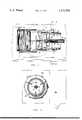
- FIG. 1is a view taken in cross section of the valve assembly comprising the present invention.
- FIG. 2is a view also taken in cross section along the line 2--2 of FIG. 1.
- a plenum chamberis illustrated which is formed from two generally rectangular boxes, which may be constructed of suitable sheet metal material, and which define chambers 2a and 2b which are placed in communication by an opening 3 passing therebetween.
- An inlet opening 4communicates with chamber 2a and a suitable outlet opening 5 is provided in chamber 2b.
- U.S. Pat. No. 4,082,114for a more detailed discussion of suitable plenum configurations for use in valve assemblies of the type under consideration.
- conduit meansare provided for admitting air to the plenum chamber through inlet opening 4 and include an adapter ring 25 which is constructed so as to be readily connected to a conditioned air duct.
- Adapter ring 25also includes a radial flange 25a which is provided for fastening the adapter ring to a wall of the plenum chamber 2a.
- the aforesaid conduit meansfurther include a generally cylindrical sleeve 6, at least a portion of which is disposed within the plenum chamber 2a, and which includes aperture means 7 passing radially therethrough for providing communication between the interior of the sleeve and the interior of the plenum chamber.
- a closure member 8is disposed at the end portion of sleeve 6 downstream from aperture means 7 so as to block axial air flow.
- valve member 9Disposed within sleeve 6 is a generally cylindrical valve member 9 which includes an axially extending portion disposed adjacent but slightly spaced from the inner pheriphery of sleeve 6. It may be noted at this time that valve member 9 further includes a plurality of web members 10 (see FIGS. 1 and 2) which connect the axially extending portion of the valve member to a centrally located hub 11. As will be appreciated by those skilled in the art, the fact that web members 10 define passage means which permit communication between the axial ends of the valve member means that the valve member is thereby substantially balanced with respect to axial pressure forces to which it is subjected.
- valve member 9is in a position intermediate the aforesaid first and second positions.
- the mounting means illustrated in the present inventionare substantially similar to that disclosed in the above-referenced U.S. Pat. No. 4,082,114 and include a bearing member 12 disposed within hub 11 of valve member 9, which bearing member rides on tubular means 13 which are supported by closure member 8 and extend axially into sleeve 6.
- actuator meansare drivingly connected to the valve member for selectively positioning same between said first and second positions, which actuator means include a rod 14 which passes through a bore in closure member 8, through tubular means 13, terminating in an end cap 14. End cap 14 is associated with a sheath 15 which is connected to hub 11 of valve member 9.
- rod 14may be suitably actuated in order to provide the desired movement and positioning of valve member 9.
- a coil spring 16is provided to impose a biasing force upon the valve member, which coil spring is in generally surrounding relationship to tubular means 13 and is restrained at its right end (as seen in FIG. 1) by a suitable spring retainer 16a.
- diaphragm meansDisposed adjacent closure member 8 are diaphragm means generally similar to those disclosed in the referenced U.S. Patent which are operably connected to rod 14 so as to provide a suitable actuating force.
- the control air pressure signalis to be derived from air pressure present in the air distribution system, the source of which may be suitable fitting such as that shown at 19.
- this air pressure sourceis utilized to supply thermostatic control circuitry in order to arrive at an appropriate control air pressure signal for admission to fitting 17.
- first sealing means 20are provided which cooperate with abutment 22 when the valve member is in its first, closed position so as to prevent air leakage thereby. Also when valve member 9 is in its first position, second sealing means 21 cooperate with an abutment 23 so as to prevent leakage.
- valve member 9When valve member 9 is in its second, fully open position, second sealing means 21 cooperate with abutment 22 so as to prevent air leakage.
- valve member 9when valve member 9 is in intermediate positions between said first and second positions, a slight gap exists between first sealing means 20 and the inner periphery of sleeve 6 so as to permit a small amount of air flow between the axially extending portion of valve member 9 and the inner periphery of sleeve 6. This small amount of air flow thus passes through the passage means as defined between web members 10 of the valve member, through the aforesaid gap, and exits via aperture means 7.
- valve assembly 9has discovered through testing of valve assemblies of the type under consideration that this small amount of air flow imposes an axial force upon valve member 9 in a direction urging same toward its first, closed position. While this force is of relatively small magnitude, it must be remembered that the actuating force available for a valve assembly of this type, which relies upon system air pressure to provide such force, is limited, more so than if a separate pneumatic air supply or suitable electrical actuating means were employed. For this reason, it has become necessary that means be devised for counteracting this axial force which results in imbalance of the valve member.
- a force balancing disc 24which, as illustrated, comprises a circular, generally planar member which is connected to hub 11 of valve member 9.
- the outer diameter of planar member 24is selected so as to serve as a restriction to the abovereferred-to small amount of air flow, whereby a pressure differential is maintained thereacross, member 24 operating according to the theory of an orifice.
- upstream of member 24exists a relatively high pressure area, while downstream therefrom is established an area of relatively low pressure.
- planar member 24includes a first generally planar surface 24a which defines a first axially projected area subjected to the relatively high pressure area, and a second, opposite, generally planar surface 24b which defines a second axially projected area subjected to the relatively low pressure area, a force is imposed thereon and transferred to valve member 9, which force is in a direction urging the valve member toward its second, open position to thereby at least partially counteract the above-mentioned axial force.
- planar member 24may be varied in accordance with the degree to which it is desired to counterbalance the axial force. Thus, in a given application, it may be desirable to counterbalance substantially all of the axial force or, in the alternative, only a portion thereof.
Landscapes
- Engineering & Computer Science (AREA)
- Physics & Mathematics (AREA)
- Fluid Mechanics (AREA)
- Chemical & Material Sciences (AREA)
- Combustion & Propulsion (AREA)
- Mechanical Engineering (AREA)
- General Engineering & Computer Science (AREA)
- Multiple-Way Valves (AREA)
Abstract
Description
Claims (6)
Priority Applications (1)
| Application Number | Priority Date | Filing Date | Title |
|---|---|---|---|
| US05/905,311US4177970A (en) | 1978-05-12 | 1978-05-12 | Valve assembly for use in an air distribution system |
Applications Claiming Priority (1)
| Application Number | Priority Date | Filing Date | Title |
|---|---|---|---|
| US05/905,311US4177970A (en) | 1978-05-12 | 1978-05-12 | Valve assembly for use in an air distribution system |
Publications (1)
| Publication Number | Publication Date |
|---|---|
| US4177970Atrue US4177970A (en) | 1979-12-11 |
Family
ID=25420619
Family Applications (1)
| Application Number | Title | Priority Date | Filing Date |
|---|---|---|---|
| US05/905,311Expired - LifetimeUS4177970A (en) | 1978-05-12 | 1978-05-12 | Valve assembly for use in an air distribution system |
Country Status (1)
| Country | Link |
|---|---|
| US (1) | US4177970A (en) |
Cited By (8)
| Publication number | Priority date | Publication date | Assignee | Title |
|---|---|---|---|---|
| US4749001A (en)* | 1987-10-19 | 1988-06-07 | American Standard Inc. | Normally closed pneumatic air valve |
| US4749000A (en)* | 1987-10-19 | 1988-06-07 | American Standard Inc. | Normally open pneumatic air valve |
| US4775133A (en)* | 1987-10-19 | 1988-10-04 | American Standard Inc. | Electric air valve |
| US4884590A (en)* | 1988-12-05 | 1989-12-05 | American Standard Inc. | Electric motor driven air valve |
| US5373987A (en)* | 1993-11-16 | 1994-12-20 | Corabatir; Kaya | Variable volume air valve |
| US5674125A (en)* | 1995-01-24 | 1997-10-07 | American Standard Inc. | Fresh air flow modulation device |
| US9260844B2 (en) | 2012-06-22 | 2016-02-16 | Kohler Mira Limited | Shower head with integrated mixing valve |
| US11391021B2 (en) | 2017-11-09 | 2022-07-19 | Kohler Mira Limited | Plumbing component |
Citations (6)
| Publication number | Priority date | Publication date | Assignee | Title |
|---|---|---|---|---|
| US2725891A (en)* | 1951-02-05 | 1955-12-06 | Cardox Corp | Hydraulically operated valve |
| US2970806A (en)* | 1960-01-21 | 1961-02-07 | Gen Electric | Balanced governing valve with minimum reaction gradients |
| US3955595A (en)* | 1973-11-15 | 1976-05-11 | Powers Regulator Company | Automatic fluid flow regulator |
| US3961748A (en)* | 1974-08-19 | 1976-06-08 | The Trane Company | Air distribution regulator apparatus |
| US3974859A (en)* | 1974-08-19 | 1976-08-17 | The Trane Company | Air distribution regulator apparatus |
| US4082114A (en)* | 1977-01-28 | 1978-04-04 | The Trane Company | Valve assembly for use in an air distribution system |
- 1978
- 1978-05-12USUS05/905,311patent/US4177970A/ennot_activeExpired - Lifetime
Patent Citations (6)
| Publication number | Priority date | Publication date | Assignee | Title |
|---|---|---|---|---|
| US2725891A (en)* | 1951-02-05 | 1955-12-06 | Cardox Corp | Hydraulically operated valve |
| US2970806A (en)* | 1960-01-21 | 1961-02-07 | Gen Electric | Balanced governing valve with minimum reaction gradients |
| US3955595A (en)* | 1973-11-15 | 1976-05-11 | Powers Regulator Company | Automatic fluid flow regulator |
| US3961748A (en)* | 1974-08-19 | 1976-06-08 | The Trane Company | Air distribution regulator apparatus |
| US3974859A (en)* | 1974-08-19 | 1976-08-17 | The Trane Company | Air distribution regulator apparatus |
| US4082114A (en)* | 1977-01-28 | 1978-04-04 | The Trane Company | Valve assembly for use in an air distribution system |
Cited By (41)
| Publication number | Priority date | Publication date | Assignee | Title |
|---|---|---|---|---|
| US4749001A (en)* | 1987-10-19 | 1988-06-07 | American Standard Inc. | Normally closed pneumatic air valve |
| US4749000A (en)* | 1987-10-19 | 1988-06-07 | American Standard Inc. | Normally open pneumatic air valve |
| US4775133A (en)* | 1987-10-19 | 1988-10-04 | American Standard Inc. | Electric air valve |
| US4884590A (en)* | 1988-12-05 | 1989-12-05 | American Standard Inc. | Electric motor driven air valve |
| US5373987A (en)* | 1993-11-16 | 1994-12-20 | Corabatir; Kaya | Variable volume air valve |
| US5674125A (en)* | 1995-01-24 | 1997-10-07 | American Standard Inc. | Fresh air flow modulation device |
| US5741180A (en)* | 1995-01-24 | 1998-04-21 | American Standard Inc. | Fresh air flor modulation device |
| US6049299A (en)* | 1995-01-24 | 2000-04-11 | American Standard Inc. | Dithering an analog signal to improve measurement |
| US9650769B2 (en) | 2012-06-22 | 2017-05-16 | Kohler Mira Limited | Mixing valve |
| US9909288B2 (en) | 2012-06-22 | 2018-03-06 | Kohler Mira Limited | Plumbing fixture with mixing valve and controller |
| US9260842B2 (en) | 2012-06-22 | 2016-02-16 | Kohler Mira Limited | Valve with heating element |
| US9273450B2 (en) | 2012-06-22 | 2016-03-01 | Kohler Mira Limited | Plumbing fixture with heating elements |
| US9340959B2 (en) | 2012-06-22 | 2016-05-17 | Kohler Mira Limited | Plumbing fixture with mixing valve and controller |
| US9340958B2 (en) | 2012-06-22 | 2016-05-17 | Kohler Mira Limited | Mixing valve |
| US9366015B2 (en) | 2012-06-22 | 2016-06-14 | Kohler Mira Limited | Method of controlling mixing valve |
| US9376792B2 (en) | 2012-06-22 | 2016-06-28 | Kohler Mira Limited | Plumbing fixture with integrated mixing valve |
| US9476188B2 (en) | 2012-06-22 | 2016-10-25 | Kohler Mira Limited | System and method for remotely disinfecting plumbing fixtures |
| US9506227B2 (en) | 2012-06-22 | 2016-11-29 | Kohler Mira Limited | Plumbing fixture with user interface |
| US9594383B2 (en) | 2012-06-22 | 2017-03-14 | Kohler Mira Limited | Shower head with integrated mixing valve |
| US9650770B2 (en) | 2012-06-22 | 2017-05-16 | Kohler Mira Limited | Mixing valve |
| US9260844B2 (en) | 2012-06-22 | 2016-02-16 | Kohler Mira Limited | Shower head with integrated mixing valve |
| US9683352B2 (en) | 2012-06-22 | 2017-06-20 | Kohler Mira Limited | Valve disinfecting method |
| US9689149B2 (en) | 2012-06-22 | 2017-06-27 | Kohler Mira Limited | Flow control valve |
| US9758950B2 (en) | 2012-06-22 | 2017-09-12 | Kohler Mira Limited | Plumbing fixture with integrated mixing valve |
| US9822513B2 (en) | 2012-06-22 | 2017-11-21 | Kohler Mira Limited | Mixing valve |
| US9260843B2 (en) | 2012-06-22 | 2016-02-16 | Kohler Mira Limited | Valve disinfecting method |
| US9920507B2 (en) | 2012-06-22 | 2018-03-20 | Kohler Mira Limited | Mixing valve |
| US9957699B2 (en) | 2012-06-22 | 2018-05-01 | Kohler Mira Limited | Plumbing fixture with heating elements |
| US9957700B2 (en) | 2012-06-22 | 2018-05-01 | Kohler Mira Limited | Valve with heating element |
| US10000914B2 (en) | 2012-06-22 | 2018-06-19 | Kohler Mira Limited | Plumbing fixture with user interface |
| US10041234B2 (en) | 2012-06-22 | 2018-08-07 | Kohler Mira Limited | Mixing valve |
| US10087607B2 (en) | 2012-06-22 | 2018-10-02 | Kohler Mira Limited | Shower head with integrated mixing valve |
| US10106964B2 (en) | 2012-06-22 | 2018-10-23 | Kohler Mira Limited | Method of controlling mixing valve |
| US10494798B2 (en) | 2012-06-22 | 2019-12-03 | Kohler Mira Limited | Plumbing fixture with heating element |
| US10501915B2 (en) | 2012-06-22 | 2019-12-10 | Kohler Mira Limited | Plumbing fixture with user interface |
| US10577784B2 (en) | 2012-06-22 | 2020-03-03 | Kohler Mira Limited | Shower head with integrated mixing valve |
| US10604919B2 (en) | 2012-06-22 | 2020-03-31 | Kohler Mira Limited | Plumbing fixture with heating element |
| US11230829B2 (en) | 2012-06-22 | 2022-01-25 | Kohler Mira Limited | Mixing valve |
| US11674293B2 (en) | 2012-06-22 | 2023-06-13 | Kohler Mira Limited | Mixing valve |
| US11391021B2 (en) | 2017-11-09 | 2022-07-19 | Kohler Mira Limited | Plumbing component |
| US12392119B2 (en) | 2017-11-09 | 2025-08-19 | Kohler Mira Limited | Plumbing component |
Similar Documents
| Publication | Publication Date | Title |
|---|---|---|
| CA1250794A (en) | Control regulator having a rolling diaphragm | |
| US2302284A (en) | Safety gas pressure regulator | |
| US4177970A (en) | Valve assembly for use in an air distribution system | |
| US2365867A (en) | Volume control for diffusers | |
| JPS5925848B2 (en) | Shroud structure for gas turbine engines | |
| US4103702A (en) | Sound proofed valve for fluid under pressure | |
| US3540484A (en) | Constant volume regulators and air distribution apparatus embodying same | |
| US3087705A (en) | Adjustable valve head | |
| GB1579662A (en) | Refrigeration control systems | |
| SE8106093L (en) | VALVE | |
| US4708166A (en) | Control valve for automatically maintaining a constant fluid flow rate | |
| JPH0569966B2 (en) | ||
| US3012583A (en) | Double-seated valve for high temperature work | |
| US2042462A (en) | Fluid flow control device | |
| US3115892A (en) | Flow controller | |
| CA1172937A (en) | Fluid flow control valve | |
| US4082114A (en) | Valve assembly for use in an air distribution system | |
| US3974859A (en) | Air distribution regulator apparatus | |
| US3019986A (en) | Fluid mixing valve | |
| US2685889A (en) | Valve of the check valve type | |
| GB999345A (en) | A valve to control fluid flow | |
| US4234013A (en) | Control valve for keeping the rate of flow at a fixed value | |
| EP0570049B1 (en) | Ball valve with offset through-duct | |
| US2920859A (en) | Balanced valve means | |
| US4749000A (en) | Normally open pneumatic air valve |
Legal Events
| Date | Code | Title | Description |
|---|---|---|---|
| AS | Assignment | Owner name:TRANE COMPANY, THE Free format text:MERGER;ASSIGNOR:A-S CAPITAL INC. A CORP OF DE;REEL/FRAME:004334/0523 | |
| AS | Assignment | Owner name:TRANE COMPANY THE Free format text:MERGER;ASSIGNORS:TRANE COMPANY THE, A CORP OF WI (INTO);A-S CAPITAL INC., A CORP OF DE (CHANGED TO);REEL/FRAME:004372/0370 Effective date:19840224 Owner name:AMERICAN STANDARD INC., A CORP OF DE Free format text:MERGER;ASSIGNORS:TRANE COMPANY, THE;A-S SALEM INC., A CORP. OF DE (MERGED INTO);REEL/FRAME:004372/0349 Effective date:19841226 | |
| AS | Assignment | Owner name:BANKERS TRUST COMPANY Free format text:SECURITY INTEREST;ASSIGNOR:AMERICAN STANDARD INC., A DE. CORP.,;REEL/FRAME:004905/0035 Effective date:19880624 Owner name:BANKERS TRUST COMPANY, 4 ALBANY STREET, 9TH FLOOR, Free format text:SECURITY INTEREST;ASSIGNOR:TRANE AIR CONDITIONING COMPANY, A DE CORP.;REEL/FRAME:004905/0213 Effective date:19880624 Owner name:BANKERS TRUST COMPANY, NEW YORK Free format text:SECURITY INTEREST;ASSIGNOR:TRANE AIR CONDITIONING COMPANY, A DE CORP.;REEL/FRAME:004905/0213 Effective date:19880624 | |
| AS | Assignment | Owner name:CHEMICAL BANK, AS COLLATERAL AGENT, NEW YORK Free format text:ASSIGNMENT OF SECURITY INTEREST;ASSIGNOR:BANKERS TRUST COMPANY, AS COLLATERAL TRUSTEE;REEL/FRAME:006565/0753 Effective date:19930601 Owner name:CHEMICAL BANK, AS COLLATERAL AGENT, NEW YORK Free format text:ASSIGNMENT OF ASSIGNORS INTEREST;ASSIGNOR:AMERICAN STANDARD INC.;REEL/FRAME:006566/0170 Effective date:19930601 | |
| AS | Assignment | Owner name:AMERICAN STANDARD, INC., NEW JERSEY Free format text:RELEASE OF SECURITY INTEREST (RE-RECORD TO CORRECT DUPLICATES SUBMITTED BY CUSTOMER. THE NEW SCHEDULE CHANGES THE TOTAL NUMBER OF PROPERTY NUMBERS INVOLVED FROM 1133 TO 794. THIS RELEASE OF SECURITY INTEREST WAS PREVIOUSLY RECORDED AT REEL 8869, FRAME 0001.);ASSIGNOR:CHASE MANHATTAN BANK, THE (FORMERLY KNOWN AS CHEMICAL BANK);REEL/FRAME:009123/0300 Effective date:19970801 |