US4176897A - EMI protected connector assembly - Google Patents
EMI protected connector assemblyDownload PDFInfo
- Publication number
- US4176897A US4176897AUS05/879,339US87933978AUS4176897AUS 4176897 AUS4176897 AUS 4176897AUS 87933978 AUS87933978 AUS 87933978AUS 4176897 AUS4176897 AUS 4176897A
- Authority
- US
- United States
- Prior art keywords
- contact
- housing
- mating portion
- plug
- electrically
- Prior art date
- Legal status (The legal status is an assumption and is not a legal conclusion. Google has not performed a legal analysis and makes no representation as to the accuracy of the status listed.)
- Expired - Lifetime
Links
Images


Classifications
- H—ELECTRICITY
- H01—ELECTRIC ELEMENTS
- H01R—ELECTRICALLY-CONDUCTIVE CONNECTIONS; STRUCTURAL ASSOCIATIONS OF A PLURALITY OF MUTUALLY-INSULATED ELECTRICAL CONNECTING ELEMENTS; COUPLING DEVICES; CURRENT COLLECTORS
- H01R13/00—Details of coupling devices of the kinds covered by groups H01R12/70 or H01R24/00 - H01R33/00
- H01R13/44—Means for preventing access to live contacts
- H01R13/447—Shutter or cover plate
- H01R13/453—Shutter or cover plate opened by engagement of counterpart
- H—ELECTRICITY
- H01—ELECTRIC ELEMENTS
- H01R—ELECTRICALLY-CONDUCTIVE CONNECTIONS; STRUCTURAL ASSOCIATIONS OF A PLURALITY OF MUTUALLY-INSULATED ELECTRICAL CONNECTING ELEMENTS; COUPLING DEVICES; CURRENT COLLECTORS
- H01R13/00—Details of coupling devices of the kinds covered by groups H01R12/70 or H01R24/00 - H01R33/00
- H01R13/648—Protective earth or shield arrangements on coupling devices, e.g. anti-static shielding
Definitions
- the present inventionis directed generally to connector assemblies, and more particularly to a connector assembly which provides uninterrupted electrical shielding and mechanical protection for associated electrical circuits in both its mated and unmated conditions.
- the present inventionprovides a connector assembly wherein the electrical contacts of the assembly are continuously and automatically shielded in both unmated and mated conditions, and during the transition between these conditions, to achieve uninterrupted protection for associated electrical circuits.
- the inventionis directed to a connector assembly comprising a receptacle housing having a plug-receiving recess at one end thereof in which a first contact assembly is positioned, and a plug housing having a mating portion thereof dimensioned to extend into the plug-receiving recess, and a second contact assembly at the end of the mating portion adapted to mate with the first contact assembly.
- closure meansare carried on at least one of the housings forwardly at the contact assembly therein for enclosing the contact assembly within the recess, the closure means opening upon insertion of the mating portion into the plug-receiving recess.
- the inventionis further directed to a connector assembly comprising a receptacle housing having a plug-receiving recess at one end thereof in which a first contact assembly is positioned, and a plug housing having a mating portion thereon dimensioned to extend into the plug-receiving recess.
- a contact assembly-receiving recessis provided at the end of the plug mating portion for receiving the first contact assembly, and a second contact assembly is positioned within the contact-receiving recess for connecting with the first contact assembly when the mating portion is seated in the first recess.
- first closure meansare provided within the first recess intermediate the ends thereof for enclosing the first contact assembly within the recess, these first closure means opening upon entry of the mating portion within the first recess, and second closure means are provided within the second recess intermediate the ends thereof for enclosing the second contact assembly within the second recess, these second closure means opening upon entry of the first contact assembly within the second recess.
- FIG. 1is a perspective view of a connector assembly constructed in accordance with the invention shown in an unmated condition.
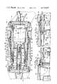
- FIG. 2is a side elevational view of the connector assembly of FIG. 1 partially in cross-section to show the principal elements of the assembly.
- FIG. 3is an enlarged cross-sectional view of the connector assembly taken along line 3--3 of FIG. 2.
- FIG. 4is an enlarged cross-sectional view of the connector assembly taken along line 4--4 of FIG. 2.
- FIG. 5is an enlarged side elevational view of the connector assembly in a mated condition partially broken away and partially in cross-section.
- FIGS. 5a and 5bdepict portions of the connector assembly shown in FIG. 5 as the connector assembly is mated.
- FIG. 6is an enlarged rear elevational view of the protective doors utilized to enclose the contacts of the connector assembly.
- FIG. 7is an enlarged perspective view of the pivoted end of one of the protective doors of FIG. 6 showing the spring assembly utilized to bias the doors to a closed position.
- FIGS. 8 and 9are enlarged cross-sectional views taken along lines 8--8 and 9--9 of FIG. 6 showing the sealing arrangement provided around the edges of the protective doors.
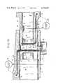
- FIG. 10is an enlarged side elevational view partially in cross-section and partially broken away of an alternate embodiment of the invention wherein electrically operated shutters are utilized in conjunction with position sensing switches to enclose the electrical contacts of the connector assembly.
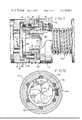
- FIG. 11is an enlarged side elevational view, partially in cross-sectional and partially broken away, of another alternate embodiment of the invention wherein mechanically operated iris-type closure mechanisms are provided to enclose the electrical contacts of the connector assembly.
- FIG. 12is a cross-sectional view of the connector assembly taken along line 12--12 of FIG. 11 illustrating the iris-type closure mechanism.
- a connector assembly 10constructed in accordance with the invention includes a plug 11 adapted to mate with a receptacle 12.
- Plug 11is intended for cable mounting, and is installed at the end of an electrical cable 13.
- Receptacle 12is intended for mounting to an external wall or bulkhead (not shown), including a flange portion 14 having fastener-receiving apertures 15 for this purpose, and is installed on the end of an electrical cable 16. Strain relief for the electrical cables and protection against probing of the electrical connections of the plug and receptacle are provided by end covers 17 and 18, respectively.
- receptacle 12includes a pair of longitudinally-extending locating pins 20 which are received in complimentarily dimensioned apertures 21 on the plug portion of the connector assembly.
- alignment pinsincrease the mechanical rigidity of the mated connector assembly and make it less susceptible to disengagement from externally applied forces.
- plug 11includes an elongated housing 22 of generally rectangular cross-section which defines an open-ended recess or compartment 23 within which a plurality of electrical contacts 24 associated with the plug are contained.
- receptacle 12includes an elongated housing 25 of generally rectangular cross-section which defines an open-ended plug-receiving recess or compartment 26 within which a plurality of electrical contacts 27 associated with the receptacle are contained.
- the interior dimensions of compartment 26allow a mating portion 22a of plug housing 22 to be slidably received therein when the connector assembly is mated.
- contacts 24 and 27are mounted in a conventional manner on individual dielectric insert blocks 28 and 29 to form contact assemblies 28a and 29a within compartments 23 and 26, respectively.
- the arrangement of the terminals on the dielectric insert blocks 28 and 29is such that when plug 11 and receptacle 12 are mated respective ones of the contacts are brought into mating engagement.
- contacts 24are shown as pin-type male contacts, and contacts 27 are shown as female contacts within the pin contacts 24 seat, it will be appreciated that contacts 24 and 27 can be of either gender, or mixed gender, and that other types of contacts, including shielded contacts, can be utilized as well.
- locking screw 30which extends through dielectric insert block 28 and into engagement with a complimentarily threaded bore 31 provided on the surface of dielectric insert block 29.
- Locking screw 30may be turned by means of a flexible drive cable 32 which rotatably couples the locating screw to suitable drive means such as a hand crank or electric motor.
- EMI and environmental protectionis provided for terminals 24 and 27 by closure means in the form of pivotally mounted doors 40 and 41 which are mounted over the open ends of compartments 23 and 26, respectively, and which automatically open when the plug and receptacle are mated.
- plug 11includes two such doors 40 pivotally mounted to opposite walls of chamber 23 and spring biased to a closed position whereby the open end of the chamber is closed.
- receptacle 12includes two such doors 41 pivotally mounted to opposite walls of chamber 26 and spring biased to a closed position whereby the open end of that chamber is closed.
- Additional sealing means in the form of an electrically-conductive spring strip 42 adjacent the open end of chamber 26are provided to establish electrical continuity between housings 22 and 25 as plug 11 and receptacle 12 are first brought into engagement and prior to either doors 40 or 41 opening.
- protective doors 40 and 41pivot into recesses 43 and 44 provided within the side walls of chambers 3 and 26, respectively.
- Protective doors 40are held open by dielectric insert block 29, which is then located within compartment 23, and protective doors 41 are held open by housing 22, which is then located within compartment 25.
- both sets of protective doorsare open, EMI shielding is maintained for contacts 24 and 27 by spring strip 42 which, by reason of being positioned at the open end of compartment 26 outwardly of protective doors 41, establishes a shielding engagement between housing 22 and housing 25 before the protective doors are pushed open. This assures that EMI protection will be maintained uninterrupted during the mating operation.
- FIGS. 5a and 5bThe mating operation is illustrated by FIGS. 5a and 5b. Initially, as the mating portion 22a of plug housing 22 is pushed into receptacle compartment 26 spring strip 42 establishes electrical continuity between housings 22 and 25. Then, as the plug housing is inserted farther, the protective doors 41 of receptacle 12 are pushed open and into recesses 44, as shown in FIG. 5a. Next, dielectric insert block 29 pushes the protective doors 40 of plug 11 open and into recess 43, as shown in FIG. 5b, allowing contacts 24 and 27 to mate, as shown in FIG. 5.
- Dielectric insert block 28is held in position by a retainer plate 45 attached to the rear end of housing 22 by machine screws 46 or other appropriate fastening means. Electrical connections are established between terminals 24 and the individual electrical conductors 47 of cable 13 in a conventional manner within insert block 28.
- the connector shell 17may be attached to housing 22 by machine screws 48 or other appropriate fastening means.
- Dielectric insert block 29is similarly held in position by a retainer plate 50 attached by machine screws 51 or other appropriate fastening means to the rear end of housing 26. Electrical connections are established between the terminals 27 of insert block 29 and the individual electrical conductors 52 of cable 16 in a conventional manner within insert block 29.
- the connector shell 18may be attached to housing 26 by machine screws 53 or other appropriate fastening means.
- the threaded bore 31 into which the locking screw 30 is threadedis located on one end of an elongated longitudinally-extending retaining member 54 slidably mounted within a bore 55 extending through the center of dielectric insert block 29.
- the other end of this retaining memberincludes a head portion of increased diameter which anchors that end to the base of end cover 18.
- Screw 30is similarly anchored to the base of end cover 17 so that as screw 30 is threaded into bore 31 plug 11 and receptacle 12 are drawn together and contacts 24 and 27 are tightly joined.
- a helical spring 56 between the inside surface of end cover 18 and the inside shoulder of retaining member 54biases that member flush with the surface of dielectric insert block 29 to facilitate starting locking screw 30 in bore 31.
- protective doors 41which are also representative of the construction of doors 40, are proportioned and arranged to fit closely though not tightly so that when closed they provide an effective barrier against EMI and environmental contamination.
- the doorshave at their opposite sides or edges pivot-receiving means in the form of lugs 60 which extend into locking engagement with transversely mounted pivot bars 61. These bars extend through the side walls of compartment 26 so as to pivotally mount each of the doors 41 on opposite side walls.
- the doorsare biased to a closed position by means of springs 62 each having two transversely spaced helical coils positioned around their respective pivot bar 61 with a central bridging portion bearing against their respective door, and with projecting end portions bearing against their respective inside wall of compartment 26.
- the doors 41are preferably formed of co-electrically conductive metal such as copper, and are arranged to bear against a gasket 63, which is seated against a shoulder 64 around the inside wall of chamber 26.
- This gasketis preferably formed of an electrically conductive elastomeric material so as to be partially compressed under the force exerted by spring 62, thereby improving electrical and mechanical sealing between housing 25 and the doors 41.
- the gasket 63is preferably L-shaped in cross-section, one leg of the L being seated against shoulder 64 and the other leg of the L being arranged to coact with the edges of the doors 41.
- the abutting central edges of the doorsmay be fitted with strips 65 of elastomeric material similar to that utilized for gasket 63. These strips are similarly compressed under the force of springs 62 when the doors are closed for improved mechanical and electrical sealing.
- protective doors 40may be identical to that of doors 41 except for size, the doors being similarly pivoted about pivot arms 67 and biased closed by springs 68.
- the spring strip 42 utilized to provide EMI protection during the mating processis compressed within a channel 66 provided around the inside wall of chamber 26.
- the spring stripis preferably formed of an electrically-conductive springy metal such as copper and is of sufficient width so as to be outwardly bowed when positioned in channel 66.
- the spring strip 42can be permanently attached to housing 25 by appropriate fastening means such as screws or rivets.
- closure means other than pivotally mounted doorscan be utilized to protect terminals 24 and 27.
- Shutter assembly 70comprises a plurality of slat-like shutters 72 mounted edge-to-edge on a semi-flexible sheet-like carrier 73 so as to slide within channels 74 provided in opposing relationship on opposite side walls of compartment 23.
- Channels 74extend from a location across the open end of chamber 23, wherein the shutters are positioned when the assembly is closed, to a rearwardly located position clear of compartment 23 wherein the shutters are positioned when the shutter assemby is open.
- the shuttersare moved within the channels by carrier 73, which is spooled onto an actuator reel 75.
- the shutter assemblyis opened by turning reel 75 in a clockwise direction (as viewed in FIG. 10), which causes carrier 73 to be wound onto the reel. This causes the shutters to be retracted into the longitudinally-extending portion of channels 74 clear of the open end of compartment 23.
- Shutter assembly 71which is similar to shutter assembly 70 except for size, includes a plurality of shutters 76 attached edge-to-edge to a semi-flexible carrier 77.
- the shuttersare constrained to slide along channels 78 provided in opposing relationship on opposite side walls of compartments 26.
- the rearwardly extending end of carrier 77is spooled onto an actuator reel 79 so that as reel 79 is turned clockwise (as viewed in FIG. 10), shutter assembly 71 is retracted to an open position.
- actuator reels 75 and 79are rotatably coupled to respective ones of electric actuator motors 80 and 81.
- the operation of these motorsis controlled by respective ones of position-sensing switches 82 and 83, which are included in conventional motor control circuits (not shown).
- housing 22depresses the actuator plunger of control switch 82, causing actuator motor 81 to turn reel 79 clockwise and move shutter assembly 71 to an open position.
- housing 25depresses the plunger of control switch 83 and causes actuator motor 80 to rotate reel 75 and retract shutter assembly 70.
- the shutter assembliesmay open very rapidly so that the insertion of plug 11 into receptacle 12 may be accomplished with one continuous motion.
- shutter assembly 71is positioned inside of the electrically conductive spring strip 42, and that control switches 82 and 83 are positioned such that housings 22 and 25 will be electrically interconnected by spring 42 prior to actuation of either switch. Thus, shutter assemblies 70 and 71 remain closed to protect contacts 24 and 27 from EMI and environmental contamination until a seal has been established between housings 22 and 25 by spring strip 42.
- shutter assemblies 70 and 71could also be retracted by means of appropriate mechanical linkages.
- rack-and-pinion assembliescould be provided in conjunction with each reel, the pinion gear of each such assembly being rotatably coupled to the associated reel, and the rack of each such assembly being arranged for actuation by the housing of the opposite half of the connector. With such an arrangement the rack members would drive their respective pinion gears after housings 22 and 25 had become interconnected by spring strip 42, so that the shutter assemblies 70 and 71 would not begin to open until EMI protection had been established.
- FIGS. 11 and 12Another possible construction for the closure means is shown in FIGS. 11 and 12 wherein iris-type shutter assemblies 88 and 89 are provided over the open ends of plug 11 and receptacle 12 respectively.
- housings 22 and 25are annular in cross-section, housing 22 being provided with a retractable donut-shaped collar 90 in which the shutter assembly 88 for plug 11 is contained.
- the shutter assembly 89 of receptacle 12may be similar to that commonly employed in the photographic field.
- the shutter assembly 89comprises a plurality of individual leafs 92 mounted to respective ones of individual pinion gears 93, which are in turn rotatably mounted to housing 25.
- the pinion gearsare rotatably coupled by means of an externally threaded ring gear 94 so that the leafs 92 are caused to extend and retract simultaneously with rotation of any one pinion gear.
- shutter assembly 89includes an actuator pin 95 positioned so as to be axially displaced upon contact with housing 22.
- Actuator pin 95includes a helical groove 96 on its surface which coacts with a pin 97 in housing 25 to impart rotary motion to the actuator pin concurrently with its axial displacement. This rotary motion is imparted to one of the pinion gears 93 by means of a spline coupling 98, so that displacement of actuator pin 95 causes rotation of ring gear 94 and simultaneous retraction of leafs 92.
- a helical spring 99 between ring gear 94 and housing 25biases leafs 92 to a closed position so that upon removal of the displacing force from actuator pin 95 the leafs return to a closed position and the actuator pin returns to an extended position.
- the iris-type shutter assembly 88 provided at the open end of compartment 22is similar in construction to assembly 89.
- This assemblyis contained within collar 90, which is forwardly biased by a helical spring 102 positioned around housing 22 so that when plug 11 is in an unmated condition the collar is fully forward.
- shutter assembly 88is closed, the individual leafs thereof (not shown) extending across the opening of compartment 22 to provide EMI and environmental protection for contacts 24.
- Shutter assembly 88includes an actuator arrangement similar to that of shutter assembly 91, an actuator pin 103 being axially displaced upon contact with housing 25 and rotatably driving a ring and pinion gear (not shown) to open the leafs of the assembly.
- actuator arrangementsare possible for opening shutter assemblies 88 and 89 upon insertion of plug 11 into receptacle 12.
- rack-and-pinion drive assemblieswherein the pinion gear of each such assembly is rotatably coupled to one of the pinion gears 93, and the rack portion of each such assembly is coupled to the housing of the other half of the connector assembly.
- motor-driven arrangementsimilar to that shown in FIG. 10 wherein the relative position of each connector member is sensed by electrical switches which cause electric motors to rotate pinion gears 93 at the appropriate portion of the mating operation.
- the connector assembly of FIG. 11may include a skirt-type spring contact 105 extending from the front end of collar 90 to establish electrical contact between housing 22 and housing 25 prior to displacement of either pin 95 or pin 103, thereby protecting contacts 24 and 27 from exposure upon opening of the shutter assemblies.
- connector assembly 10for closing the open ends of compartments 22 and 26.
- connector assembly 10for closing the open ends of compartments 22 and 26.
- FIGS. 1-9it would be possible to utilize a single protective door pivoted at one end in plug 11 and receptacle 12. The operation of these doors would be similar to that of doors 40 and 41, except that larger recesses would be required on the inside walls of compartments 23 and 26 to accommodate these doors in their retracted positions.
Landscapes
- Details Of Connecting Devices For Male And Female Coupling (AREA)
- Connector Housings Or Holding Contact Members (AREA)
Abstract
Description
Claims (31)
Priority Applications (1)
| Application Number | Priority Date | Filing Date | Title |
|---|---|---|---|
| US05/879,339US4176897A (en) | 1976-11-19 | 1978-02-21 | EMI protected connector assembly |
Applications Claiming Priority (2)
| Application Number | Priority Date | Filing Date | Title |
|---|---|---|---|
| US74330276A | 1976-11-19 | 1976-11-19 | |
| US05/879,339US4176897A (en) | 1976-11-19 | 1978-02-21 | EMI protected connector assembly |
Related Parent Applications (1)
| Application Number | Title | Priority Date | Filing Date |
|---|---|---|---|
| US74330276AContinuation | 1976-11-19 | 1976-11-19 |
Publications (1)
| Publication Number | Publication Date |
|---|---|
| US4176897Atrue US4176897A (en) | 1979-12-04 |
Family
ID=27114131
Family Applications (1)
| Application Number | Title | Priority Date | Filing Date |
|---|---|---|---|
| US05/879,339Expired - LifetimeUS4176897A (en) | 1976-11-19 | 1978-02-21 | EMI protected connector assembly |
Country Status (1)
| Country | Link |
|---|---|
| US (1) | US4176897A (en) |
Cited By (63)
| Publication number | Priority date | Publication date | Assignee | Title |
|---|---|---|---|---|
| US4345808A (en)* | 1980-11-20 | 1982-08-24 | International Telephone And Telegraph Corporation | Electrical connector |
| US4349241A (en)* | 1980-05-09 | 1982-09-14 | Bunker Ramo Corporation | Electrical connector assembly having enhanced EMI shielding |
| US4468075A (en)* | 1980-07-28 | 1984-08-28 | Fujitsu Limited | Structure of electrical connecting device |
| US4475784A (en)* | 1982-12-02 | 1984-10-09 | The Singer Company | Cartridge and receptacle for use with an electronically controlled appliance |
| US4493517A (en)* | 1980-12-03 | 1985-01-15 | Wkr Limited | Electrical socket connector |
| US4674807A (en)* | 1986-03-03 | 1987-06-23 | Harvey Hubbell Incorporated | Shielded connector |
| US4758536A (en)* | 1986-09-18 | 1988-07-19 | Amp Incorporated | Receptacle for premise wiring system |
| GB2209633A (en)* | 1987-09-08 | 1989-05-17 | Strix Ltd | Shuttered electrical connectors |
| FR2669153A1 (en)* | 1990-11-12 | 1992-05-15 | Courtaigne Bertrand | Connector element fitted with a cover with automatic opening and closing, connector comprising it and container gripping frame equipped with such a connector element |
| US5348487A (en)* | 1992-05-20 | 1994-09-20 | Diamond Sa | Plug connector for optical fibers |
| US5372515A (en)* | 1993-06-10 | 1994-12-13 | Martin Marietta Corporation | Mechanical ESD protector |
| US5466163A (en)* | 1994-04-06 | 1995-11-14 | Mcdonnell Douglas Corporation | Umbilical mechanism |
| US5669776A (en)* | 1996-09-11 | 1997-09-23 | The United States Of America As Represented By The Secretary Of The Navy | Cable connector assembly |
| US5681187A (en)* | 1995-08-29 | 1997-10-28 | Yazaki Corporation | Connector with movable contact member and resilient contact band |
| US5716224A (en)* | 1994-11-10 | 1998-02-10 | Yazaki Corporation | Connector with shutter mechanism |
| US5717533A (en)* | 1995-01-13 | 1998-02-10 | Methode Electronics Inc. | Removable optoelectronic module |
| GB2317754A (en)* | 1996-09-26 | 1998-04-01 | Smiths Industries Plc | Electrical coupling |
| US5879173A (en)* | 1995-01-13 | 1999-03-09 | Methode Electronics, Inc. | Removable transceiver module and receptacle |
| USRE36820E (en)* | 1995-01-13 | 2000-08-15 | Methode Electronics, Inc. | Removable optoelectronic module |
| US6179627B1 (en) | 1998-04-22 | 2001-01-30 | Stratos Lightwave, Inc. | High speed interface converter module |
| US6203333B1 (en) | 1998-04-22 | 2001-03-20 | Stratos Lightwave, Inc. | High speed interface converter module |
| US6220878B1 (en) | 1995-10-04 | 2001-04-24 | Methode Electronics, Inc. | Optoelectronic module with grounding means |
| US6220873B1 (en)* | 1999-08-10 | 2001-04-24 | Stratos Lightwave, Inc. | Modified contact traces for interface converter |
| JP3163967B2 (en) | 1995-10-19 | 2001-05-08 | 住友電装株式会社 | Electromagnetic coupling device for charging electric vehicles |
| US6454580B1 (en)* | 2001-08-22 | 2002-09-24 | Hon Hai Precision Ind. Co., Ltd. | Guide rail for receiving a GBIC module |
| US6464517B1 (en)* | 2001-11-27 | 2002-10-15 | Hon Hai Precision Ind. Co., Ltd. | GBIC having spring-mounted shielding door |
| US20020177336A1 (en)* | 2001-05-25 | 2002-11-28 | Naotaka Sasame | Electrical connector with shutter and electrical connector assembly |
| US6520782B2 (en)* | 2001-01-23 | 2003-02-18 | Yazaki Corporation | Connector with shutter mechanism |
| US20030034997A1 (en)* | 1995-02-23 | 2003-02-20 | Mckain James A. | Combined editing system and digital moving picture recording system |
| US20030040207A1 (en)* | 2001-08-21 | 2003-02-27 | Mitutoyo Corporation | Output-attached measuring instrument |
| US20030148645A1 (en)* | 2002-02-05 | 2003-08-07 | Tyco Electronics Amp K.K | Connector shutter |
| US6607308B2 (en) | 2001-02-12 | 2003-08-19 | E20 Communications, Inc. | Fiber-optic modules with shielded housing/covers having mixed finger types |
| US6659655B2 (en) | 2001-02-12 | 2003-12-09 | E20 Communications, Inc. | Fiber-optic modules with housing/shielding |
| US20040110402A1 (en)* | 2002-09-30 | 2004-06-10 | Jones Randall T. | Electrical connector assembly |
| US20050053352A1 (en)* | 1995-04-07 | 2005-03-10 | Mckain James A. | Combined editing system and digital moving picture recording system |
| US6960923B2 (en)* | 2001-12-19 | 2005-11-01 | Formfactor, Inc. | Probe card covering system and method |
| US6977673B1 (en) | 1995-02-23 | 2005-12-20 | Avid Technology, Inc. | Portable moving picture recording device including switching control for multiple data flow configurations |
| US7090509B1 (en) | 1999-06-11 | 2006-08-15 | Stratos International, Inc. | Multi-port pluggable transceiver (MPPT) with multiple LC duplex optical receptacles |
| US20070032112A1 (en)* | 2003-08-01 | 2007-02-08 | Oscar Renautt | Self-adjustable junction connector system |
| USRE40150E1 (en) | 1994-04-25 | 2008-03-11 | Matsushita Electric Industrial Co., Ltd. | Fiber optic module |
| EP1970503A1 (en)* | 2007-03-16 | 2008-09-17 | ABB Technology AG | Transformer station, method for installing a transformer station and docking station for a transformer |
| US7623754B1 (en) | 1995-02-23 | 2009-11-24 | Avid Technology, Inc. | Motion picture recording device using digital, computer-readable non-linear media |
| US20120028484A1 (en)* | 2010-08-02 | 2012-02-02 | Ever Win International Corporation | Automatic Sliding Door |
| US20120178291A1 (en)* | 2009-09-24 | 2012-07-12 | Yakazaki Corporation | Device-connecting connector |
| EP2523261A1 (en)* | 2011-05-10 | 2012-11-14 | Souriau | Sealed connection assembly |
| DE102012105771A1 (en)* | 2012-06-29 | 2014-04-10 | Phoenix Contact Gmbh & Co. Kg | Plug with contact socket and protective cover |
| JP2017071361A (en)* | 2015-10-09 | 2017-04-13 | 株式会社ニフコ | Filling port device |
| US9944240B1 (en)* | 2016-10-06 | 2018-04-17 | Ford Global Technologies Llc | Iris seal power outlet closure |
| US9958617B2 (en)* | 2016-01-25 | 2018-05-01 | Neutrik Ag | Connector |
| US9975440B1 (en)* | 2017-05-04 | 2018-05-22 | Ford Global Technologies, Llc | Charge port covering assembly and method |
| US20180151975A1 (en)* | 2016-11-29 | 2018-05-31 | Intel Corporation | Data connector with movable cover |
| US10345537B2 (en) | 2015-03-18 | 2019-07-09 | Neutrik Ag | Plug part and plug-in connection |
| EP3750731A1 (en)* | 2019-06-11 | 2020-12-16 | Jungheinrich Aktiengesellschaft | Charging socket |
| WO2021002876A1 (en)* | 2019-07-04 | 2021-01-07 | Hewlett-Packard Development Company, L.P. | Connector |
| US11046196B2 (en)* | 2018-07-26 | 2021-06-29 | Ford Global Technologies, Llc | Charge port covering assembly and method |
| US20210231882A1 (en)* | 2018-06-29 | 2021-07-29 | 3M Innovative Properties Company | Connector with pivoting magnetic door |
| EP3827482A4 (en)* | 2018-09-11 | 2021-09-15 | Magna International Inc. | PLUG ARRANGEMENT WITH ENVIRONMENTAL AND ELECTRICAL PROTECTION |
| DE102020115415A1 (en) | 2020-06-10 | 2021-12-16 | Volkswagen Aktiengesellschaft | Coupling device for connecting high-voltage connections |
| US20220320781A1 (en)* | 2021-04-05 | 2022-10-06 | Yazaki Corporation | Connector |
| US20220320782A1 (en)* | 2021-04-05 | 2022-10-06 | Yazaki Corporation | Connector |
| US11547282B2 (en)* | 2016-05-25 | 2023-01-10 | avateramedical GmBH | Arrangement for the sterile handling of non-sterile units in a sterile environment |
| US20230328913A1 (en)* | 2022-04-06 | 2023-10-12 | Juniper Networks, Inc. | Self-actuating protective cover device for connectors of a field-replaceable unit |
| WO2023209537A1 (en)* | 2022-04-25 | 2023-11-02 | Te Connectivity Solutions Gmbh | Charging system for a mobile device |
Citations (5)
| Publication number | Priority date | Publication date | Assignee | Title |
|---|---|---|---|---|
| US1060011A (en)* | 1911-08-12 | 1913-04-29 | Metropolitan Electric Mfg Co | Flush receptacle. |
| US2379942A (en)* | 1942-12-31 | 1945-07-10 | Bell Telephone Labor Inc | Cable terminating means |
| US3519975A (en)* | 1968-03-25 | 1970-07-07 | Itt | Electrical connector |
| US3521222A (en)* | 1967-11-24 | 1970-07-21 | Bunker Ramo | Cable connector |
| US4033654A (en)* | 1976-07-29 | 1977-07-05 | Automation Industries, Inc. | Electrical connector |
- 1978
- 1978-02-21USUS05/879,339patent/US4176897A/ennot_activeExpired - Lifetime
Patent Citations (5)
| Publication number | Priority date | Publication date | Assignee | Title |
|---|---|---|---|---|
| US1060011A (en)* | 1911-08-12 | 1913-04-29 | Metropolitan Electric Mfg Co | Flush receptacle. |
| US2379942A (en)* | 1942-12-31 | 1945-07-10 | Bell Telephone Labor Inc | Cable terminating means |
| US3521222A (en)* | 1967-11-24 | 1970-07-21 | Bunker Ramo | Cable connector |
| US3519975A (en)* | 1968-03-25 | 1970-07-07 | Itt | Electrical connector |
| US4033654A (en)* | 1976-07-29 | 1977-07-05 | Automation Industries, Inc. | Electrical connector |
Cited By (98)
| Publication number | Priority date | Publication date | Assignee | Title |
|---|---|---|---|---|
| US4349241A (en)* | 1980-05-09 | 1982-09-14 | Bunker Ramo Corporation | Electrical connector assembly having enhanced EMI shielding |
| US4468075A (en)* | 1980-07-28 | 1984-08-28 | Fujitsu Limited | Structure of electrical connecting device |
| US4345808A (en)* | 1980-11-20 | 1982-08-24 | International Telephone And Telegraph Corporation | Electrical connector |
| US4493517A (en)* | 1980-12-03 | 1985-01-15 | Wkr Limited | Electrical socket connector |
| US4475784A (en)* | 1982-12-02 | 1984-10-09 | The Singer Company | Cartridge and receptacle for use with an electronically controlled appliance |
| US4674807A (en)* | 1986-03-03 | 1987-06-23 | Harvey Hubbell Incorporated | Shielded connector |
| US4758536A (en)* | 1986-09-18 | 1988-07-19 | Amp Incorporated | Receptacle for premise wiring system |
| GB2209633A (en)* | 1987-09-08 | 1989-05-17 | Strix Ltd | Shuttered electrical connectors |
| FR2669153A1 (en)* | 1990-11-12 | 1992-05-15 | Courtaigne Bertrand | Connector element fitted with a cover with automatic opening and closing, connector comprising it and container gripping frame equipped with such a connector element |
| US5348487A (en)* | 1992-05-20 | 1994-09-20 | Diamond Sa | Plug connector for optical fibers |
| US5372515A (en)* | 1993-06-10 | 1994-12-13 | Martin Marietta Corporation | Mechanical ESD protector |
| US5466163A (en)* | 1994-04-06 | 1995-11-14 | Mcdonnell Douglas Corporation | Umbilical mechanism |
| USRE40154E1 (en) | 1994-04-25 | 2008-03-18 | Matsushita Electric Industrial Co., Ltd. | Fiber optic module |
| USRE40150E1 (en) | 1994-04-25 | 2008-03-11 | Matsushita Electric Industrial Co., Ltd. | Fiber optic module |
| US5716224A (en)* | 1994-11-10 | 1998-02-10 | Yazaki Corporation | Connector with shutter mechanism |
| USRE36820E (en)* | 1995-01-13 | 2000-08-15 | Methode Electronics, Inc. | Removable optoelectronic module |
| US6267606B1 (en) | 1995-01-13 | 2001-07-31 | Stratos Lightwave, Inc. | Removable transceiver module and receptacle |
| US5879173A (en)* | 1995-01-13 | 1999-03-09 | Methode Electronics, Inc. | Removable transceiver module and receptacle |
| US5717533A (en)* | 1995-01-13 | 1998-02-10 | Methode Electronics Inc. | Removable optoelectronic module |
| US6201704B1 (en) | 1995-01-13 | 2001-03-13 | Stratos Lightwave, Inc. | Transceive module with EMI shielding |
| US7623754B1 (en) | 1995-02-23 | 2009-11-24 | Avid Technology, Inc. | Motion picture recording device using digital, computer-readable non-linear media |
| US6977673B1 (en) | 1995-02-23 | 2005-12-20 | Avid Technology, Inc. | Portable moving picture recording device including switching control for multiple data flow configurations |
| US7830413B2 (en) | 1995-02-23 | 2010-11-09 | Avid Technology, Inc. | Combined editing system and digital moving picture recording system |
| US20030034997A1 (en)* | 1995-02-23 | 2003-02-20 | Mckain James A. | Combined editing system and digital moving picture recording system |
| US7230641B2 (en) | 1995-02-23 | 2007-06-12 | Avid Technolgy, Inc. | Combined editing system and digital moving picture recording system |
| US20050053352A1 (en)* | 1995-04-07 | 2005-03-10 | Mckain James A. | Combined editing system and digital moving picture recording system |
| US7532807B2 (en) | 1995-04-07 | 2009-05-12 | Avid Technology, Inc. | Combined editing system and digital moving picture recording system |
| US5681187A (en)* | 1995-08-29 | 1997-10-28 | Yazaki Corporation | Connector with movable contact member and resilient contact band |
| US6220878B1 (en) | 1995-10-04 | 2001-04-24 | Methode Electronics, Inc. | Optoelectronic module with grounding means |
| JP3163967B2 (en) | 1995-10-19 | 2001-05-08 | 住友電装株式会社 | Electromagnetic coupling device for charging electric vehicles |
| US5669776A (en)* | 1996-09-11 | 1997-09-23 | The United States Of America As Represented By The Secretary Of The Navy | Cable connector assembly |
| GB2317754B (en)* | 1996-09-26 | 2001-01-17 | Smiths Industries Plc | Electrical connector assemblies |
| GB2317754A (en)* | 1996-09-26 | 1998-04-01 | Smiths Industries Plc | Electrical coupling |
| US6179627B1 (en) | 1998-04-22 | 2001-01-30 | Stratos Lightwave, Inc. | High speed interface converter module |
| US6203333B1 (en) | 1998-04-22 | 2001-03-20 | Stratos Lightwave, Inc. | High speed interface converter module |
| US7090509B1 (en) | 1999-06-11 | 2006-08-15 | Stratos International, Inc. | Multi-port pluggable transceiver (MPPT) with multiple LC duplex optical receptacles |
| US6220873B1 (en)* | 1999-08-10 | 2001-04-24 | Stratos Lightwave, Inc. | Modified contact traces for interface converter |
| DE10202408B4 (en)* | 2001-01-23 | 2004-12-16 | Yazaki Corp. | Electrical connector with a locking mechanism |
| US6520782B2 (en)* | 2001-01-23 | 2003-02-18 | Yazaki Corporation | Connector with shutter mechanism |
| US6659655B2 (en) | 2001-02-12 | 2003-12-09 | E20 Communications, Inc. | Fiber-optic modules with housing/shielding |
| US6607308B2 (en) | 2001-02-12 | 2003-08-19 | E20 Communications, Inc. | Fiber-optic modules with shielded housing/covers having mixed finger types |
| US6874953B2 (en) | 2001-02-12 | 2005-04-05 | Jds Uniphase Corporation | Methods and apparatus for fiber-optic modules with shielded housings/covers with fingers |
| EP1261073A3 (en)* | 2001-05-25 | 2004-03-31 | Tyco Electronics AMP K.K. | Electrical connector with shutter and electrical connector assembly |
| US6832923B2 (en)* | 2001-05-25 | 2004-12-21 | Tyco Electronics. Amp, K.K. | Electrical connector with shutter and electrical connector assembly |
| US20020177336A1 (en)* | 2001-05-25 | 2002-11-28 | Naotaka Sasame | Electrical connector with shutter and electrical connector assembly |
| US6671976B2 (en)* | 2001-08-21 | 2004-01-06 | Mitutoyo Corporation | Output-attached measuring instrument |
| US20030040207A1 (en)* | 2001-08-21 | 2003-02-27 | Mitutoyo Corporation | Output-attached measuring instrument |
| US6454580B1 (en)* | 2001-08-22 | 2002-09-24 | Hon Hai Precision Ind. Co., Ltd. | Guide rail for receiving a GBIC module |
| US6464517B1 (en)* | 2001-11-27 | 2002-10-15 | Hon Hai Precision Ind. Co., Ltd. | GBIC having spring-mounted shielding door |
| US20060057875A1 (en)* | 2001-12-19 | 2006-03-16 | Formfactor, Inc. | Probe card covering system and method |
| US7128587B2 (en)* | 2001-12-19 | 2006-10-31 | Formfactor, Inc. | Probe card covering system and method |
| US6960923B2 (en)* | 2001-12-19 | 2005-11-01 | Formfactor, Inc. | Probe card covering system and method |
| US6877999B2 (en)* | 2002-02-05 | 2005-04-12 | Tyco Electronics Amp K.K. | Connector shutter |
| US20030148645A1 (en)* | 2002-02-05 | 2003-08-07 | Tyco Electronics Amp K.K | Connector shutter |
| US20040110402A1 (en)* | 2002-09-30 | 2004-06-10 | Jones Randall T. | Electrical connector assembly |
| US6835076B2 (en)* | 2002-09-30 | 2004-12-28 | Delphi Technologies, Inc. | Electrical connector assembly |
| US20070032112A1 (en)* | 2003-08-01 | 2007-02-08 | Oscar Renautt | Self-adjustable junction connector system |
| US8198966B2 (en) | 2007-03-16 | 2012-06-12 | Abb Technology Ag | Docking station for a transformer and method for installation of a transformer station |
| US20080222969A1 (en)* | 2007-03-16 | 2008-09-18 | Abb Technology Ag | Docking station for a transformer and method for installation of a transformer station |
| EP1970503A1 (en)* | 2007-03-16 | 2008-09-17 | ABB Technology AG | Transformer station, method for installing a transformer station and docking station for a transformer |
| CN101267090B (en)* | 2007-03-16 | 2013-05-22 | Abb技术有限公司 | Substation and method for installing a substation |
| US20120178291A1 (en)* | 2009-09-24 | 2012-07-12 | Yakazaki Corporation | Device-connecting connector |
| US8956172B2 (en)* | 2009-09-24 | 2015-02-17 | Yazaki Corporation | Device-connecting connector |
| US20120028484A1 (en)* | 2010-08-02 | 2012-02-02 | Ever Win International Corporation | Automatic Sliding Door |
| EP2523261A1 (en)* | 2011-05-10 | 2012-11-14 | Souriau | Sealed connection assembly |
| FR2975231A1 (en)* | 2011-05-10 | 2012-11-16 | Souriau | SEALED CONNECTION ASSEMBLY |
| US8770860B2 (en) | 2011-05-10 | 2014-07-08 | Souriau | Tightly sealed connection assembly with pivoting valves |
| DE102012105771A1 (en)* | 2012-06-29 | 2014-04-10 | Phoenix Contact Gmbh & Co. Kg | Plug with contact socket and protective cover |
| DE102012105771B4 (en)* | 2012-06-29 | 2016-06-16 | Phoenix Contact Gmbh & Co. Kg | Plug with contact socket and protective cover |
| US10345537B2 (en) | 2015-03-18 | 2019-07-09 | Neutrik Ag | Plug part and plug-in connection |
| CN108367673A (en)* | 2015-10-09 | 2018-08-03 | 株式会社利富高 | Oil-feed port device |
| US10500948B2 (en) | 2015-10-09 | 2019-12-10 | Nifco Inc. | Fuel filling device |
| JP2017071361A (en)* | 2015-10-09 | 2017-04-13 | 株式会社ニフコ | Filling port device |
| US9958617B2 (en)* | 2016-01-25 | 2018-05-01 | Neutrik Ag | Connector |
| US11547282B2 (en)* | 2016-05-25 | 2023-01-10 | avateramedical GmBH | Arrangement for the sterile handling of non-sterile units in a sterile environment |
| US9944240B1 (en)* | 2016-10-06 | 2018-04-17 | Ford Global Technologies Llc | Iris seal power outlet closure |
| US10824360B2 (en)* | 2016-11-29 | 2020-11-03 | Intel Corporation | Data connector with movable cover |
| US20180151975A1 (en)* | 2016-11-29 | 2018-05-31 | Intel Corporation | Data connector with movable cover |
| US9975440B1 (en)* | 2017-05-04 | 2018-05-22 | Ford Global Technologies, Llc | Charge port covering assembly and method |
| US20210231882A1 (en)* | 2018-06-29 | 2021-07-29 | 3M Innovative Properties Company | Connector with pivoting magnetic door |
| US11046196B2 (en)* | 2018-07-26 | 2021-06-29 | Ford Global Technologies, Llc | Charge port covering assembly and method |
| US11387595B2 (en) | 2018-09-11 | 2022-07-12 | Magna International Inc. | Connector arrangement with environmental and electrical protection |
| EP3827482A4 (en)* | 2018-09-11 | 2021-09-15 | Magna International Inc. | PLUG ARRANGEMENT WITH ENVIRONMENTAL AND ELECTRICAL PROTECTION |
| EP3750731A1 (en)* | 2019-06-11 | 2020-12-16 | Jungheinrich Aktiengesellschaft | Charging socket |
| US11784433B2 (en) | 2019-07-04 | 2023-10-10 | Hewlett-Packard Development Company, L.P. | Connector |
| WO2021002876A1 (en)* | 2019-07-04 | 2021-01-07 | Hewlett-Packard Development Company, L.P. | Connector |
| DE102020115415A1 (en) | 2020-06-10 | 2021-12-16 | Volkswagen Aktiengesellschaft | Coupling device for connecting high-voltage connections |
| US11721926B2 (en)* | 2021-04-05 | 2023-08-08 | Yazaki Corporation | Connector with an interlocking rotation mechanism |
| JP2022159862A (en)* | 2021-04-05 | 2022-10-18 | 矢崎総業株式会社 | connector |
| JP2022159904A (en)* | 2021-04-05 | 2022-10-18 | 矢崎総業株式会社 | connector |
| US11715903B2 (en)* | 2021-04-05 | 2023-08-01 | Yazaki Corporation | Connector including a rotatble connection member |
| US20220320781A1 (en)* | 2021-04-05 | 2022-10-06 | Yazaki Corporation | Connector |
| US20220320782A1 (en)* | 2021-04-05 | 2022-10-06 | Yazaki Corporation | Connector |
| JP7548864B2 (en) | 2021-04-05 | 2024-09-10 | 矢崎総業株式会社 | connector |
| JP7548863B2 (en) | 2021-04-05 | 2024-09-10 | 矢崎総業株式会社 | connector |
| US20230328913A1 (en)* | 2022-04-06 | 2023-10-12 | Juniper Networks, Inc. | Self-actuating protective cover device for connectors of a field-replaceable unit |
| US12328836B2 (en)* | 2022-04-06 | 2025-06-10 | Juniper Networks, Inc. | Self-actuating protective cover device for connectors of a field-replaceable unit |
| WO2023209537A1 (en)* | 2022-04-25 | 2023-11-02 | Te Connectivity Solutions Gmbh | Charging system for a mobile device |
Similar Documents
| Publication | Publication Date | Title |
|---|---|---|
| US4176897A (en) | EMI protected connector assembly | |
| US4217019A (en) | EMI protected connector assembly | |
| US4838808A (en) | Shielded electrical connector and latch mechanism therefor | |
| US5718596A (en) | Connector engaging structure | |
| US4758536A (en) | Receptacle for premise wiring system | |
| DE69415079T2 (en) | Electrical connectors | |
| US6592384B2 (en) | Waterproof low insertion force connector | |
| US4493517A (en) | Electrical socket connector | |
| US4921441A (en) | Shielded backshell system having strain relief and shield continuity | |
| US3345604A (en) | Electrical connector | |
| US10950996B2 (en) | Multiplex connecting device capable of switching an operability of a single connector thereof | |
| US4386819A (en) | RF Shielded assembly having capacitive coupling feature | |
| DE4302153C2 (en) | Electrically insulating connector protection housing | |
| US3500291A (en) | Locking electrical connector | |
| EP0105810A3 (en) | An electrical connector having an anti-decoupling device | |
| HK1000400B (en) | Mountable connector for cable assembly | |
| DE102017204166A1 (en) | connector | |
| US4488765A (en) | Dead-faced electrical connector with electromagnetic vulnerability protection | |
| HK1000400A1 (en) | Mountable connector for cable assembly | |
| EP4142068B1 (en) | Connector device | |
| WO2007080166A1 (en) | Electrical plug-and-socket device | |
| DE19649705A1 (en) | Electrical connector with a magnetic interlock e.g. for hot water preparation device | |
| US5913691A (en) | Dual power/control connector | |
| US5554045A (en) | Latch for IC card connector | |
| US4514024A (en) | Shielded electrical connector |
Legal Events
| Date | Code | Title | Description |
|---|---|---|---|
| AS | Assignment | Owner name:ALLIED CORPORATION COLUMBIA ROAD AND PARK AVENUE, Free format text:ASSIGNMENT OF ASSIGNORS INTEREST.;ASSIGNOR:BUNKER RAMO CORPORATION A CORP. OF DE;REEL/FRAME:004149/0365 Effective date:19820922 Owner name:ALLIED CORPORATION A CORP. OF NY, NEW JERSEY Free format text:ASSIGNMENT OF ASSIGNORS INTEREST;ASSIGNOR:BUNKER RAMO CORPORATION A CORP. OF DE;REEL/FRAME:004149/0365 Effective date:19820922 | |
| AS | Assignment | Owner name:CANADIAN IMPERIAL BANK OF COMMERCE, NEW YORK AGENC Free format text:SECURITY INTEREST;ASSIGNOR:AMPHENOL CORPORATION;REEL/FRAME:004879/0030 Effective date:19870515 | |
| AS | Assignment | Owner name:AMPHENOL CORPORATION, LISLE, ILLINOIS A CORP. OF D Free format text:ASSIGNMENT OF ASSIGNORS INTEREST.;ASSIGNOR:ALLIED CORPORATION, A CORP. OF NY;REEL/FRAME:004844/0850 Effective date:19870602 Owner name:AMPHENOL CORPORATION, A CORP. OF DE, ILLINOIS Free format text:ASSIGNMENT OF ASSIGNORS INTEREST;ASSIGNOR:ALLIED CORPORATION, A CORP. OF NY;REEL/FRAME:004844/0850 Effective date:19870602 | |
| AS | Assignment | Owner name:BANKERS TRUST COMPANY, AS AGENT Free format text:SECURITY INTEREST;ASSIGNOR:AMPHENOL CORPORATION, A CORPORATION OF DE;REEL/FRAME:006035/0283 Effective date:19911118 | |
| AS | Assignment | Owner name:AMPHENOL CORPORATION A CORP. OF DELAWARE Free format text:RELEASED BY SECURED PARTY;ASSIGNOR:CANADIAN IMPERIAL BANK OF COMMERCE;REEL/FRAME:006147/0887 Effective date:19911114 | |
| AS | Assignment | Owner name:AMPHENOL CORPORATION, CONNECTICUT Free format text:RELEASE BY SECURED PARTY;ASSIGNOR:BANKERS TRUST COMPANY;REEL/FRAME:007317/0148 Effective date:19950104 |