US4174828A - Bayonet clamping apparatus for machine tools - Google Patents
Bayonet clamping apparatus for machine toolsDownload PDFInfo
- Publication number
- US4174828A US4174828AUS05/829,358US82935877AUS4174828AUS 4174828 AUS4174828 AUS 4174828AUS 82935877 AUS82935877 AUS 82935877AUS 4174828 AUS4174828 AUS 4174828A
- Authority
- US
- United States
- Prior art keywords
- workpiece
- fixture
- piston
- openings
- pin
- Prior art date
- Legal status (The legal status is an assumption and is not a legal conclusion. Google has not performed a legal analysis and makes no representation as to the accuracy of the status listed.)
- Expired - Lifetime
Links
Images


Classifications
- B—PERFORMING OPERATIONS; TRANSPORTING
- B23—MACHINE TOOLS; METAL-WORKING NOT OTHERWISE PROVIDED FOR
- B23Q—DETAILS, COMPONENTS, OR ACCESSORIES FOR MACHINE TOOLS, e.g. ARRANGEMENTS FOR COPYING OR CONTROLLING; MACHINE TOOLS IN GENERAL CHARACTERISED BY THE CONSTRUCTION OF PARTICULAR DETAILS OR COMPONENTS; COMBINATIONS OR ASSOCIATIONS OF METAL-WORKING MACHINES, NOT DIRECTED TO A PARTICULAR RESULT
- B23Q7/00—Arrangements for handling work specially combined with or arranged in, or specially adapted for use in connection with, machine tools, e.g. for conveying, loading, positioning, discharging, sorting
- B23Q7/14—Arrangements for handling work specially combined with or arranged in, or specially adapted for use in connection with, machine tools, e.g. for conveying, loading, positioning, discharging, sorting co-ordinated in production lines
- B23Q7/1426—Arrangements for handling work specially combined with or arranged in, or specially adapted for use in connection with, machine tools, e.g. for conveying, loading, positioning, discharging, sorting co-ordinated in production lines with work holders not rigidly fixed to the transport devices
- B—PERFORMING OPERATIONS; TRANSPORTING
- B23—MACHINE TOOLS; METAL-WORKING NOT OTHERWISE PROVIDED FOR
- B23Q—DETAILS, COMPONENTS, OR ACCESSORIES FOR MACHINE TOOLS, e.g. ARRANGEMENTS FOR COPYING OR CONTROLLING; MACHINE TOOLS IN GENERAL CHARACTERISED BY THE CONSTRUCTION OF PARTICULAR DETAILS OR COMPONENTS; COMBINATIONS OR ASSOCIATIONS OF METAL-WORKING MACHINES, NOT DIRECTED TO A PARTICULAR RESULT
- B23Q1/00—Members which are comprised in the general build-up of a form of machine, particularly relatively large fixed members
- B23Q1/25—Movable or adjustable work or tool supports
- B23Q1/26—Movable or adjustable work or tool supports characterised by constructional features relating to the co-operation of relatively movable members; Means for preventing relative movement of such members
- B23Q1/38—Movable or adjustable work or tool supports characterised by constructional features relating to the co-operation of relatively movable members; Means for preventing relative movement of such members using fluid bearings or fluid cushion supports
- B—PERFORMING OPERATIONS; TRANSPORTING
- B23—MACHINE TOOLS; METAL-WORKING NOT OTHERWISE PROVIDED FOR
- B23Q—DETAILS, COMPONENTS, OR ACCESSORIES FOR MACHINE TOOLS, e.g. ARRANGEMENTS FOR COPYING OR CONTROLLING; MACHINE TOOLS IN GENERAL CHARACTERISED BY THE CONSTRUCTION OF PARTICULAR DETAILS OR COMPONENTS; COMBINATIONS OR ASSOCIATIONS OF METAL-WORKING MACHINES, NOT DIRECTED TO A PARTICULAR RESULT
- B23Q16/00—Equipment for precise positioning of tool or work into particular locations not otherwise provided for
- B23Q16/001—Stops, cams, or holders therefor
- B—PERFORMING OPERATIONS; TRANSPORTING
- B23—MACHINE TOOLS; METAL-WORKING NOT OTHERWISE PROVIDED FOR
- B23Q—DETAILS, COMPONENTS, OR ACCESSORIES FOR MACHINE TOOLS, e.g. ARRANGEMENTS FOR COPYING OR CONTROLLING; MACHINE TOOLS IN GENERAL CHARACTERISED BY THE CONSTRUCTION OF PARTICULAR DETAILS OR COMPONENTS; COMBINATIONS OR ASSOCIATIONS OF METAL-WORKING MACHINES, NOT DIRECTED TO A PARTICULAR RESULT
- B23Q3/00—Devices holding, supporting, or positioning work or tools, of a kind normally removable from the machine
- B23Q3/02—Devices holding, supporting, or positioning work or tools, of a kind normally removable from the machine for mounting on a work-table, tool-slide, or analogous part
- B23Q3/10—Auxiliary devices, e.g. bolsters, extension members
- B23Q3/103—Constructional elements used for constructing work holders
- B—PERFORMING OPERATIONS; TRANSPORTING
- B25—HAND TOOLS; PORTABLE POWER-DRIVEN TOOLS; MANIPULATORS
- B25B—TOOLS OR BENCH DEVICES NOT OTHERWISE PROVIDED FOR, FOR FASTENING, CONNECTING, DISENGAGING OR HOLDING
- B25B5/00—Clamps
- B25B5/06—Arrangements for positively actuating jaws
- B25B5/061—Arrangements for positively actuating jaws with fluid drive
Definitions
- the present inventionrelates to a clamping system for clamping a workpiece or workpiece fixture to the supporting table of a machine tool, and in particular to a bayonet clamping system which is suitable for use with work tables when the fixture is floatingly supported on a film of pressurized air during movement from one machining position to another.
- a work table of this typeis shown and described in the above-identified patent and is designed to eliminate the time consuming, laborious positioning of the workpiece or fixture in the machine tool as various regions of the workpiece are to be machined.
- the tablehas passages therein which supply fluid under pressure between the downwardly facing surface of the fixture and the upwardly facing horizontal surface of the table so that the fixture "floats" on the film of air and can be moved about easily on the table.
- Cooperating elements of pin and socket locating devices on the fixture and tableprovide for the accurate locating of the fixture in predetermined positions on the table.
- the present inventionovercomes the problems and disadvantages of the prior art by providing a plurality of openings distributed over the table surface into which clamping elements are insertable and locked therein by a relatively simple motion.
- clamping pressuremay be applied at any desired position on the table.
- automatic clampingis effected by a hydraulic piston and cylinder mounted within the table and engageable with the locking pin to draw it downwardly and exert clamping pressure when actuated.
- automatic clampingis effected by a hydraulic cylinder mounted toward the top of the clamping elements and exerts a downward pressure when actuated.
- the present inventionis concerned with apparatus for clamping a workpiece or workpiece fixture in a machine tool comprising: a table having a surface adapted to support a workpiece or workpiece fixture thereon, a plurality of openings in a table having removable cover means thereover, a plurality of first clamp elements being mounted within the table below and accessible through the openings, a second clamp element adapted to be removably inserted in any of the openings and including means for selectively mechanically interlocking with the first element mounted below the opening in which the second element is inserted, a third element on the second clamp element adapted to engage a workpiece or workpiece fixture supported on the table surface, and means for drawing the third element toward the table surface whereby a workpiece or fixture supported on the table and engaged by the third element will be clamped therebetween.
- Another object of the present inventionis to provide a bayonet clamping system for machine tools wherein clamping pressure at a wide variety of positions on the table may be applied.
- a further object of the present inventionis to provide a bayonet clamping system for machine tools having tables of the air float type wherein the table may be formed without T-slots thereby enabling lower pneumatic pressures. For example, heavy loads can be lifted 0.007 in. with as little as 20 psi of pneumatic pressure.
- a further object of the present inventionis to provide a bayonet clamping system for machine tools enabling a relatively smooth and uninterrupted table work surface.
- a still further object of the present inventionis to provide a bayonet clamping system for machine tools which reduces machine down time for purposes of clearing chips and shavings out of the T-slots, as is necessary to existing work tables.
- Yet another object of the present inventionis to provide a bayonet clamping system wherein clamping pressure may be exerted automatically by means of fluid actuators.
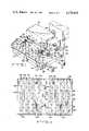
- FIG. 1is a perspective view of a machine tool wherein the supporting table is provided with a bayonet clamping system according to the present invention
- FIG. 2is a top plan view of the table shown in FIG. 1;
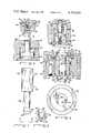
- FIG. 3is a sectional view of one of the valved connections leading from a passage in the table to the surface on which the workpiece fixture is supported;
- FIG. 4is a sectional view of one of the locating pins shown engaged with a corresponding socket in the lower surface of the workpiece fixture;
- FIG. 5is a sectional view of a retractable centering pin
- FIG. 6is a sectional view of one of the hydraulic actuators of FIG. 1 taken along line 6--6;
- FIG. 7is a side elevational view of one of the male clamping elements
- FIG. 8is an end view of the male clamping element shown in FIG. 7;
- FIG. 9is a top plan view of the hydraulic actuator shown in FIG. 6 with the pin removed;
- FIG. 10is a hydraulic schematic for the clamping system of the present invention.
- FIG. 11is a sectional view of a modified form of the present invention.
- FIG. 12is an end view of the male clamp element shown in FIG. 11;
- FIG. 13is a sectional view of a manual clamping device according to the present invention.
- FIGS. 14 and 15are perspective and sectional views respectively, and of a modified form of the present invention.
- FIG. 16is a sectional view of one of the covered bayonet clamp openings.
- FIG. 1is a perspective view of a machine tool having a bed 20 supported on ways 22 and 24 and a working tool 26, which may be a boring tool, milling tool or the like according to well known practice in the machine tool art.
- a table or plate 28is fixedly secured to bed 20 and includes an upper surface 30 on which is supported a workpiece fixture 32 having a workpiece 34 mounted thereon.
- Table 28is provided with a plurality of fluid passageways 36 (FIG. 3) which are connected via a control valve (not shown) with a supply of fluid under pressure.
- the fluid under pressureis preferably air, but could conceivably comprise another fluid medium.
- Passageways 36extend upwardly through table 28 and communicate with opening 38 in the surface 30 of table 28. As shown in FIGS. 1 and 2, there are many such openings 38 distributed over the table surface 30 so as to provide a film of pressurized air wherever the fixture 32 is positioned.
- the upper end of each passagewayis closed by a valve comprising a body 40 which may be threaded into passageway 36 and the top of which is disposed slightly below the level of table surface 30.
- Valve body 40is tubular and has captured therein a valve ball 42 which projects slightly above the surface 30 of table 28 as shown in FIG. 3.
- a spring 44urges ball 42 into its upper closed position in which it contacts circular valve seat 46.
- table 28includes a main centering pin 50 (FIG. 5) reciprocably received within a bore 52 in table surface 30. Integrally formed with pin 50 is a piston 54 reciprocably received within chamber 56 and which is actuated by means of fluid pressure applied through passageways 58 and 60.
- Fixture 32is provided with a downwardly opening bore (not shown) which receives centering pin 50 when the same is extended to its upper position above the surface 30 of table 28.
- a slot (not shown) in the lower surface 48 of fixture 32may be provided so as to enable translation of fixture 32.
- locating pins 62which serve to accurately locate the fixture in various predetermined positions.
- the locating pins 62are located in precise positions on table 28 with reference to the tool 26. These pins 62 are engageable with sockets 64 provided in the bottom surface 48 of fixture 32 and which are also accurately located within the fixtures 32 with reference to the location of pins 62. Thus, when one or more pins 62 engage the corresponding sockets 64 in the bottom of the fixture 32, the fixture 32 will be in an accurately located position on the table 28.
- the centering pin 50engages the fixture, only one of locating pins 62 is required to determine fixture location. Alternatively, two locating pins 62 could be employed and the fixture location determined thereby without depending on pivot pin 50.
- Table 28is provided with bores 66 each of which at the upper end thereof has an elongated bushing 68.
- Pin 70having a tapered upper end 72 adapted for seating in the correspondingly tapered bushing 74 in socket 64, is slidably received in bushing 68.
- pin 70is connected with a double acting piston 76 biased upwardly by spring 78 to the position shown in FIG. 4.
- Each piston 76has an upwardly facing fluid surface 80 adapted to be acted on by fluid from passageway 82 to drive the piston 76 and pin 70 downwardly until the upper end 72 of the pin is below the upper surface 30 of table 28.
- a supply of fluid pressure to the downwardly facing surface 84 from passageway 86will drive piston 76 upwardly to effect firm engagement of the tapered end 32 with bushing 74.
- the lower end of bore 88is closed by cover plate 90.
- table 28is provided with a number of locating pins 62 so that a number of successive machining positions of workpiece 34 and fixture 32 may be realized.
- pin 70By supplying air under pressure to the upper side 80 of piston 76, pin 70 will be moved downwardly out of bushing 74. If fluid under pressure is then introduced between fixture 32 and table 28, fixture 32 may be moved to the desired position. With the fixture 32 in this position, pneumatic pressure is vented from passageway 82 and pin 70 will move upwardly under the pressure of spring 78 until its tapered portion 72 engages bushing 74. Pin 70 may be driven with more force into bushing 74 by admitting pressure through conduit 86. With the fixture 32 accurately located in this manner, the supply of pneumatic pressure between fixture 32 and table 28 is then terminated and fixture 32 will come to rest on surface 30. Additional details relating to the air float table described herein may be found in the previously identified U.S. Pat. No. 4,058,885.
- FIGS. 6, 7, 8, 9 and 10One embodiment of the present invention is illustrated in FIGS. 6, 7, 8, 9 and 10. It comprises a hydraulic cylinder 92 threadedly secured to an elongated plate 94 which is slidably received within elongated slots in table 28. A specially designed piston 96 is reciprocably received within cylinder 92 and has an elongated opening 98 extending therethrough. Bushing 100 is threadedly secured to piston 92 and sealed against piston 96 and cylinder 92 by means of O-rings 102 and 104, respectively. Seal 106 seals the other end of working chamber 108 which is defined on one end by annular piston face 110 and on the other end by housing 100. Piston 96 is urged to its upper position (FIG.
- Cylinders 92 and their respective pistons 96are located beneath openings 120 in table surface 30. Any desired number of openings 120 and piston and cylinders 96, 98 may be provided but it is preferable that there be a sufficient number to permit clamping at any desired position on the table surface 30. Cylinders 92 are accurately positioned underneath their respective openings 120 by plates 94 which slide into T-slots 95 until their ends 122, which are wider than slots 95, abut the side 124 of table 28. Any suitable means such as tapered pins 126, may be employed for locking plates 94 in their respective T-slots 95.
- the male clamping elementcomprises a pin 128 (FIGS. 7 and 8) having a shank portion 130 adapted to be inserted through the opening or bore 98 of piston 96, an enlarged head 132 which is dimensioned to be received within opening 120 and abut annular shoulder 134, and a locking portion 136 having a pair of lugs or ears 138 and 140.
- Locking portion 136is dimensioned to pass through piston bore 98 when lugs 138 and 140 are aligned with the longitudinal dimension of bore 98.
- bore 98is somewhat elongated in the horizontal direction and the downwardly facing surfaces 142 and 144 of piston 96 will abut lugs 138 and 140 when pin 128 is rotated a quarter turn.
- the head 132 of pin 128is provided with a threaded socket 150 adapted to receive a suitably threaded bolt or rod 151 for the purpose described below.
- FIGS. 11 and 12Another embodiment of the present invention is shown in FIGS. 11 and 12 and comprises a cylinder 152 threadedly attached to elongated plate 154, the latter being received within a T-slot 156 in table 28.
- a piston 158is reciprocably received in cylinder 152 and includes a cylindrical bore 160 extending therethrough. Piston 158 is retracted by the application of fluid pressure through passageway 162 and is urged to its upward position (FIG. 11) by compressed spring 164.
- the device shown in FIG. 11is virtually identical to that shown in FIG. 6.
- the pin 166is threadedly secured to piston 154 by means of a pair of interrupted high pitch threads 168 which engage with corresponding female threads 170.
- the pitch of threads 168 and 170is sufficiently high to enable pin 166 to be tightened within piston 158 with less than a full turn, for example, a quarter turn.
- Pin 166includes female threads 172 so as to permit connection of a threaded rod similar to rod 151. If desired, regular, non-interrupted threads may be employed.
- the hydraulic system for the clamping system describedis shown schematically in FIG. 10 and comprises a three-way valve 174 connected to a source of pneumatic pressure over line 176, an air over hydraulic booster 178 having a high pressure hydraulic output line 180 which connects with cylinders 92 (or cylinders 152) through quick disconnect coupler 182.
- Fixture 32is floated on its film of pressurized air to the desired position, accurately located by means of locating pins 70 and then brought to rest on table 28 by interrupting the supply of pneumatic pressure to passageways 36.
- pins 128are inserted through their respective openings 120 and pistons 196 and then turned 90° so as to be locked in place (FIG. 6).
- Blocks 184are then set in place and slotted clamping bars 186 are placed over rods 151 and suspended between blocks 184 and fixture 32. Washers 188 are placed over the ends of rods 151 and tightened against clamping bars 186 by nuts 190.
- FIG. 11operates in a similar fashion to the embodiment just described except that pin 166 is screwed into piston 158.
- This embodimenthas the advantage that a smaller piston and cylinder may be employed.
- a manual clamping embodimentis shown in FIG. 13 and comprises a pin 194 identical to pin 128 received in a stepped opening 196 in table 198.
- the female element 200which has an internal horizontal section similar to piston 96, is threaded into a downwardly facing bore 202 in table 198.
- Clamping bar 204is pulled downwardly by tightening nut 206 on threaded rod 208, which is in turn threadedly connected to pin 194.
- An unused bayonet opening 196is shown closed by a cover 192 in FIG. 16.
- FIGS. 14 and 15A further modification to the present invention is illustrated in FIGS. 14 and 15 and comprises a pin 210 similar to pin 194 received in a stepped opening 212 in table 214.
- the female element 216is similar to element 200 and threaded into bore 218 and engages the end of pin 210.
- Hydraulic cylinder 220which is similar to the one shown in FIGS. 6 and 11, is received over rod 222 between nut 224 and clamping bar 225 and spacer 223. When energized, cylinder 220 exerts downward force on bar 225 through spacer 223 so as to clamp a workpiece 226 as shown in FIG. 14. All of the clamps are preferably energized simultaneously.
Landscapes
- Engineering & Computer Science (AREA)
- Mechanical Engineering (AREA)
- Jigs For Machine Tools (AREA)
Abstract
Description
Claims (14)
Priority Applications (5)
| Application Number | Priority Date | Filing Date | Title |
|---|---|---|---|
| US05/829,358US4174828A (en) | 1976-05-10 | 1977-08-31 | Bayonet clamping apparatus for machine tools |
| DE7878900098TDE2861810D1 (en) | 1977-08-31 | 1978-08-28 | Bayonet clamping apparatus for machine tools |
| PCT/US1978/000073WO1979000117A1 (en) | 1977-08-31 | 1978-08-28 | Bayonet clamping apparatus for machine tools |
| JP10694178AJPS5447187A (en) | 1977-08-31 | 1978-08-31 | Apparatus for tightening work or work fixture to machine tool |
| EP19780900098EP0006899B1 (en) | 1977-08-31 | 1979-03-13 | Bayonet clamping apparatus for machine tools |
Applications Claiming Priority (2)
| Application Number | Priority Date | Filing Date | Title |
|---|---|---|---|
| US05/684,725US4058885A (en) | 1976-05-10 | 1976-05-10 | Method for locating and clamping a work member supporting fixture |
| US05/829,358US4174828A (en) | 1976-05-10 | 1977-08-31 | Bayonet clamping apparatus for machine tools |
Related Parent Applications (1)
| Application Number | Title | Priority Date | Filing Date |
|---|---|---|---|
| US05/684,725Continuation-In-PartUS4058885A (en) | 1976-05-10 | 1976-05-10 | Method for locating and clamping a work member supporting fixture |
Publications (1)
| Publication Number | Publication Date |
|---|---|
| US4174828Atrue US4174828A (en) | 1979-11-20 |
Family
ID=27103419
Family Applications (1)
| Application Number | Title | Priority Date | Filing Date |
|---|---|---|---|
| US05/829,358Expired - LifetimeUS4174828A (en) | 1976-05-10 | 1977-08-31 | Bayonet clamping apparatus for machine tools |
Country Status (1)
| Country | Link |
|---|---|
| US (1) | US4174828A (en) |
Cited By (46)
| Publication number | Priority date | Publication date | Assignee | Title |
|---|---|---|---|---|
| US4326831A (en)* | 1976-05-10 | 1982-04-27 | Bergman Raymond A | Apparatus for transferring a workpiece in an air float system |
| FR2510017A1 (en)* | 1981-07-21 | 1983-01-28 | Aioi Seiki Kk | PLATE FOR ATTACHING A PLURALITY OF WORKPIECES, FOR MACHINE TOOL |
| DE3222224A1 (en)* | 1982-06-12 | 1983-12-15 | AIOI Seiki K.K., Itami, Hyogo | Workpiece replacement device for machine tools |
| FR2530520A1 (en)* | 1982-06-03 | 1984-01-27 | Aioi Seiki Kk | Device for the exchange of workpieces on machine tools. |
| US4445675A (en)* | 1980-12-02 | 1984-05-01 | Aioi Seiki Kabushiki Kaisha | Work-clamping unit for use in machine tools |
| US4468019A (en)* | 1981-05-29 | 1984-08-28 | A Romheld GmbH & Co. KG | Pallet clamping system for machine tools |
| US4500079A (en)* | 1984-01-30 | 1985-02-19 | General Dynamics Corporation/Convair Div. | Removable and replaceable locating pin for locating a workpiece on a sub-plate for machining |
| DE3341542A1 (en)* | 1983-11-17 | 1985-05-30 | Günter 3548 Arolsen Meywald | Clamping device for use on or in machining stations of machine tools |
| US4583631A (en)* | 1981-08-04 | 1986-04-22 | Aioi Keiki K.K. | Apparatus for positioning and clamping work clamp pallet for machine tools |
| US4610440A (en)* | 1983-11-25 | 1986-09-09 | Mors | Self-contained workpiece-holding device, preferably equipped with an operating system, and also advantageously provided with individual power-cylinder operating means for operating it at an independent pressure |
| DE3511393A1 (en)* | 1985-03-29 | 1986-10-02 | Aeg-Elotherm Gmbh, 5630 Remscheid | Electrical-discharge machine with a work head rigidly arranged above the work table |
| US4695047A (en)* | 1986-10-14 | 1987-09-22 | Carr Lane Roemheld Manufacturing Co., Inc. | T-slot hydraulic clamp system |
| EP0267117A1 (en)* | 1986-11-06 | 1988-05-11 | AEROSPATIALE SOCIETE NATIONALE INDUSTRIELLE, Société Anonyme | System for clamping work pieces and installation for carrying out operations on these pieces |
| US4909493A (en)* | 1987-12-25 | 1990-03-20 | Kabushiki Kaisha Kosmek | Cylinder type hydraulic clamp |
| EP0320027A3 (en)* | 1987-12-10 | 1990-05-23 | SALVAGNINI S.p.A. | Pallet with adjustable anchorage system for equipping the clamping fixture of a rough piece to be machined with machine tools |
| EP0356717A3 (en)* | 1988-09-02 | 1990-08-29 | Hans Kolbe & Co. | Supporting table for printed-circuit board drill units |
| US4958813A (en)* | 1989-09-28 | 1990-09-25 | Delaware Capital Formation, Inc. | Die clamp |
| US5110099A (en)* | 1990-06-05 | 1992-05-05 | Kabushiki Kaisha Kosmek | Hydraulic clamp with direct operated clamping-member |
| US5190273A (en)* | 1987-12-10 | 1993-03-02 | Sz S.R.L. | Pallet with adjustable anchorage system for equipping the clamping fixture of a rough piece to be machined with machine tools |
| US5192058A (en)* | 1992-01-02 | 1993-03-09 | Vektek, Inc. | Swing clamp |
| US5257774A (en)* | 1992-11-22 | 1993-11-02 | Delaware Capital Formation, Inc. | Power actuated pull clamp |
| US5312154A (en)* | 1993-02-01 | 1994-05-17 | Darrel Woodall | Apparatus for holding down workpieces to be machined |
| US5439205A (en)* | 1993-02-20 | 1995-08-08 | Firma Gerhard Haberle | Vacuum-type work piece clamping device |
| EP0761382A1 (en)* | 1995-09-07 | 1997-03-12 | Günter Lang | Device for positioning pieces in clamping devices |
| EP0785049A1 (en)* | 1996-01-15 | 1997-07-23 | Cianci, Pasquale, Dipl.-Ing | Support table with clamping device |
| US5743687A (en)* | 1995-01-30 | 1998-04-28 | Ribic; John | Fourth axis fixture quick change |
| US20070262507A1 (en)* | 2006-05-15 | 2007-11-15 | Bayer Jack L | Bayer work piece clamping system |
| CN101829921A (en)* | 2010-06-12 | 2010-09-15 | 太原煤气化股份有限公司 | Table clamp |
| DE102009052747A1 (en) | 2009-11-11 | 2011-05-19 | Sporer, Klaus, Dipl.-Ing. | Positioning device for clamping system, particularly vice, is provided with stop element which is moved relative to clamping area between positions in which stop element emerges relative to clamping surface |
| DE102011010726B3 (en)* | 2011-02-09 | 2012-07-12 | Kacema GmbH | Clamping device for a machine tool |
| CN103480915A (en)* | 2013-09-22 | 2014-01-01 | 遵义宏港机械有限公司 | Method for processing power supply cover fillet |
| CN103770044A (en)* | 2014-01-14 | 2014-05-07 | 中国科学院上海光学精密机械研究所 | Six-freedom degree adjusting mounting mechanism |
| CN104669159A (en)* | 2014-12-29 | 2015-06-03 | 广州广电计量检测股份有限公司 | Automotive fuel pump vibration test fixture |
| US9259816B2 (en)* | 2012-09-07 | 2016-02-16 | Fu Tai Hua Industry (Shenzhen) Co., Ltd. | Locking mechanism |
| CN106181815A (en)* | 2016-08-10 | 2016-12-07 | 成都杰仕德科技有限公司 | A kind of fixture, clamp assembly and fixture external member |
| CN106312871A (en)* | 2015-07-14 | 2017-01-11 | 蒋红娟 | Automatic clamping fixture |
| CN106514519A (en)* | 2017-01-04 | 2017-03-22 | 温州兴南环保科技有限公司 | Automatic mechanical clamp |
| CN106737308A (en)* | 2017-02-24 | 2017-05-31 | 中信戴卡股份有限公司 | Flexible clamping device |
| CN106926168A (en)* | 2017-04-27 | 2017-07-07 | 浙江大学 | A wing root rib positioning device |
| CN106944976A (en)* | 2017-03-29 | 2017-07-14 | 晨辉婴宝儿童用品有限公司 | A kind of frock and method that protective case is assembled on U-shaped bar |
| CN106976032A (en)* | 2017-04-27 | 2017-07-25 | 浙江大学 | A kind of assembly tooling system of large aircraft outer wing wing box |
| CN109227292A (en)* | 2018-10-17 | 2019-01-18 | 宁波市江北欣盛数控机械有限公司 | A kind of cross workpiece grinding machine and control method |
| CN109227183A (en)* | 2018-11-26 | 2019-01-18 | 法兰泰克重工股份有限公司 | A kind of clamping apparatus |
| CN109454486A (en)* | 2018-12-18 | 2019-03-12 | 广东原点智能技术有限公司 | A kind of frock clamp |
| CN111283226A (en)* | 2020-03-25 | 2020-06-16 | 纽威数控装备(苏州)股份有限公司 | Floating clamping mechanism for lathe worktable and lathe |
| CN114161314A (en)* | 2021-11-03 | 2022-03-11 | 山东常林机械集团股份有限公司 | Pneumatic suspension type process equipment and method for honing valve hole of high-pressure valve body |
Citations (4)
| Publication number | Priority date | Publication date | Assignee | Title |
|---|---|---|---|---|
| US2421957A (en)* | 1944-01-24 | 1947-06-10 | Mead Specialties Company Inc | Work holding apparatus |
| US2428111A (en)* | 1943-05-05 | 1947-09-30 | Eldrup Niels | Work clamping unit |
| US3055654A (en)* | 1960-02-03 | 1962-09-25 | Harrison Henry | Screw clamp |
| US3209623A (en)* | 1962-10-15 | 1965-10-05 | Schardt Rudolf | Pneumatic positioning table |
- 1977
- 1977-08-31USUS05/829,358patent/US4174828A/ennot_activeExpired - Lifetime
Patent Citations (4)
| Publication number | Priority date | Publication date | Assignee | Title |
|---|---|---|---|---|
| US2428111A (en)* | 1943-05-05 | 1947-09-30 | Eldrup Niels | Work clamping unit |
| US2421957A (en)* | 1944-01-24 | 1947-06-10 | Mead Specialties Company Inc | Work holding apparatus |
| US3055654A (en)* | 1960-02-03 | 1962-09-25 | Harrison Henry | Screw clamp |
| US3209623A (en)* | 1962-10-15 | 1965-10-05 | Schardt Rudolf | Pneumatic positioning table |
Cited By (54)
| Publication number | Priority date | Publication date | Assignee | Title |
|---|---|---|---|---|
| US4326831A (en)* | 1976-05-10 | 1982-04-27 | Bergman Raymond A | Apparatus for transferring a workpiece in an air float system |
| US4445675A (en)* | 1980-12-02 | 1984-05-01 | Aioi Seiki Kabushiki Kaisha | Work-clamping unit for use in machine tools |
| US4468019A (en)* | 1981-05-29 | 1984-08-28 | A Romheld GmbH & Co. KG | Pallet clamping system for machine tools |
| FR2510017A1 (en)* | 1981-07-21 | 1983-01-28 | Aioi Seiki Kk | PLATE FOR ATTACHING A PLURALITY OF WORKPIECES, FOR MACHINE TOOL |
| US4583631A (en)* | 1981-08-04 | 1986-04-22 | Aioi Keiki K.K. | Apparatus for positioning and clamping work clamp pallet for machine tools |
| FR2530520A1 (en)* | 1982-06-03 | 1984-01-27 | Aioi Seiki Kk | Device for the exchange of workpieces on machine tools. |
| DE3222224A1 (en)* | 1982-06-12 | 1983-12-15 | AIOI Seiki K.K., Itami, Hyogo | Workpiece replacement device for machine tools |
| DE3341542A1 (en)* | 1983-11-17 | 1985-05-30 | Günter 3548 Arolsen Meywald | Clamping device for use on or in machining stations of machine tools |
| US4610440A (en)* | 1983-11-25 | 1986-09-09 | Mors | Self-contained workpiece-holding device, preferably equipped with an operating system, and also advantageously provided with individual power-cylinder operating means for operating it at an independent pressure |
| EP0149375B1 (en)* | 1983-11-25 | 1988-10-12 | Mors | Work pallet, provided with a control system and preferably with a separate cylinder control, to operate with an independent pressure |
| US4500079A (en)* | 1984-01-30 | 1985-02-19 | General Dynamics Corporation/Convair Div. | Removable and replaceable locating pin for locating a workpiece on a sub-plate for machining |
| DE3511393A1 (en)* | 1985-03-29 | 1986-10-02 | Aeg-Elotherm Gmbh, 5630 Remscheid | Electrical-discharge machine with a work head rigidly arranged above the work table |
| US4695047A (en)* | 1986-10-14 | 1987-09-22 | Carr Lane Roemheld Manufacturing Co., Inc. | T-slot hydraulic clamp system |
| EP0267117A1 (en)* | 1986-11-06 | 1988-05-11 | AEROSPATIALE SOCIETE NATIONALE INDUSTRIELLE, Société Anonyme | System for clamping work pieces and installation for carrying out operations on these pieces |
| FR2606309A1 (en)* | 1986-11-06 | 1988-05-13 | Aerospatiale | SYSTEM FOR CLAMPING WORKPIECES AND INSTALLATION FOR CARRYING OUT OPERATIONS ON SAID PARTS |
| US5190273A (en)* | 1987-12-10 | 1993-03-02 | Sz S.R.L. | Pallet with adjustable anchorage system for equipping the clamping fixture of a rough piece to be machined with machine tools |
| EP0320027A3 (en)* | 1987-12-10 | 1990-05-23 | SALVAGNINI S.p.A. | Pallet with adjustable anchorage system for equipping the clamping fixture of a rough piece to be machined with machine tools |
| US4909493A (en)* | 1987-12-25 | 1990-03-20 | Kabushiki Kaisha Kosmek | Cylinder type hydraulic clamp |
| EP0322617A3 (en)* | 1987-12-25 | 1990-05-09 | Kabushiki Kaisha Kosmek | Cylinder type hydraulic clamp |
| EP0356717A3 (en)* | 1988-09-02 | 1990-08-29 | Hans Kolbe & Co. | Supporting table for printed-circuit board drill units |
| US4958813A (en)* | 1989-09-28 | 1990-09-25 | Delaware Capital Formation, Inc. | Die clamp |
| US5110099A (en)* | 1990-06-05 | 1992-05-05 | Kabushiki Kaisha Kosmek | Hydraulic clamp with direct operated clamping-member |
| US5192058A (en)* | 1992-01-02 | 1993-03-09 | Vektek, Inc. | Swing clamp |
| US5257774A (en)* | 1992-11-22 | 1993-11-02 | Delaware Capital Formation, Inc. | Power actuated pull clamp |
| US5312154A (en)* | 1993-02-01 | 1994-05-17 | Darrel Woodall | Apparatus for holding down workpieces to be machined |
| US5439205A (en)* | 1993-02-20 | 1995-08-08 | Firma Gerhard Haberle | Vacuum-type work piece clamping device |
| US5743687A (en)* | 1995-01-30 | 1998-04-28 | Ribic; John | Fourth axis fixture quick change |
| EP0761382A1 (en)* | 1995-09-07 | 1997-03-12 | Günter Lang | Device for positioning pieces in clamping devices |
| EP0785049A1 (en)* | 1996-01-15 | 1997-07-23 | Cianci, Pasquale, Dipl.-Ing | Support table with clamping device |
| US20070262507A1 (en)* | 2006-05-15 | 2007-11-15 | Bayer Jack L | Bayer work piece clamping system |
| US8002254B2 (en)* | 2006-05-15 | 2011-08-23 | Jack Leon Bayer | Bayer work piece clamping system |
| DE102009052747A1 (en) | 2009-11-11 | 2011-05-19 | Sporer, Klaus, Dipl.-Ing. | Positioning device for clamping system, particularly vice, is provided with stop element which is moved relative to clamping area between positions in which stop element emerges relative to clamping surface |
| CN101829921A (en)* | 2010-06-12 | 2010-09-15 | 太原煤气化股份有限公司 | Table clamp |
| EP2487009A1 (en) | 2011-02-09 | 2012-08-15 | Kacema GmbH | Clamping device for a machine tool |
| DE102011010726B3 (en)* | 2011-02-09 | 2012-07-12 | Kacema GmbH | Clamping device for a machine tool |
| US9259816B2 (en)* | 2012-09-07 | 2016-02-16 | Fu Tai Hua Industry (Shenzhen) Co., Ltd. | Locking mechanism |
| CN103480915A (en)* | 2013-09-22 | 2014-01-01 | 遵义宏港机械有限公司 | Method for processing power supply cover fillet |
| CN103770044A (en)* | 2014-01-14 | 2014-05-07 | 中国科学院上海光学精密机械研究所 | Six-freedom degree adjusting mounting mechanism |
| CN103770044B (en)* | 2014-01-14 | 2015-09-16 | 中国科学院上海光学精密机械研究所 | Six degree of freedom adjustment installing mechanism |
| CN104669159A (en)* | 2014-12-29 | 2015-06-03 | 广州广电计量检测股份有限公司 | Automotive fuel pump vibration test fixture |
| CN106312871A (en)* | 2015-07-14 | 2017-01-11 | 蒋红娟 | Automatic clamping fixture |
| CN106181815A (en)* | 2016-08-10 | 2016-12-07 | 成都杰仕德科技有限公司 | A kind of fixture, clamp assembly and fixture external member |
| CN106514519A (en)* | 2017-01-04 | 2017-03-22 | 温州兴南环保科技有限公司 | Automatic mechanical clamp |
| CN106737308A (en)* | 2017-02-24 | 2017-05-31 | 中信戴卡股份有限公司 | Flexible clamping device |
| CN106944976A (en)* | 2017-03-29 | 2017-07-14 | 晨辉婴宝儿童用品有限公司 | A kind of frock and method that protective case is assembled on U-shaped bar |
| CN106944976B (en)* | 2017-03-29 | 2019-01-25 | 晨辉婴宝儿童用品有限公司 | A tooling and method for assembling a protective sleeve on a U-shaped rod |
| CN106926168A (en)* | 2017-04-27 | 2017-07-07 | 浙江大学 | A wing root rib positioning device |
| CN106976032A (en)* | 2017-04-27 | 2017-07-25 | 浙江大学 | A kind of assembly tooling system of large aircraft outer wing wing box |
| CN106926168B (en)* | 2017-04-27 | 2018-08-24 | 浙江大学 | A wing root rib positioning device |
| CN109227292A (en)* | 2018-10-17 | 2019-01-18 | 宁波市江北欣盛数控机械有限公司 | A kind of cross workpiece grinding machine and control method |
| CN109227183A (en)* | 2018-11-26 | 2019-01-18 | 法兰泰克重工股份有限公司 | A kind of clamping apparatus |
| CN109454486A (en)* | 2018-12-18 | 2019-03-12 | 广东原点智能技术有限公司 | A kind of frock clamp |
| CN111283226A (en)* | 2020-03-25 | 2020-06-16 | 纽威数控装备(苏州)股份有限公司 | Floating clamping mechanism for lathe worktable and lathe |
| CN114161314A (en)* | 2021-11-03 | 2022-03-11 | 山东常林机械集团股份有限公司 | Pneumatic suspension type process equipment and method for honing valve hole of high-pressure valve body |
Similar Documents
| Publication | Publication Date | Title |
|---|---|---|
| US4174828A (en) | Bayonet clamping apparatus for machine tools | |
| US4275983A (en) | Air float fixture clamping system | |
| US4901990A (en) | Machine tool fixture with air supply system | |
| US4058885A (en) | Method for locating and clamping a work member supporting fixture | |
| US4143868A (en) | Centering pin for air float machine tool tables | |
| JPS6237623Y2 (en) | ||
| JP2556134Y2 (en) | Work clamp device for horizontal machine tools | |
| EP0006899B1 (en) | Bayonet clamping apparatus for machine tools | |
| CN110936204B (en) | Machining clamp for disc brake bracket | |
| CA2114086A1 (en) | Vacuum clamping plate | |
| CN215035615U (en) | A multifunctional vice | |
| JPS5943066Y2 (en) | Machine tool work clamp device | |
| US4298307A (en) | Air float power rotation system | |
| US5743687A (en) | Fourth axis fixture quick change | |
| US3830485A (en) | Work table for machine tools | |
| US4179106A (en) | Apparatus for locating and clamping a work member supporting fixture | |
| CN101176973A (en) | Cramping arrangement of guide block rough milling gap | |
| KR100804239B1 (en) | Cylinder testing device | |
| US4489924A (en) | Hydraulically actuated clamping table assembly | |
| WO1979000156A1 (en) | Centering pin for air float machine tool tables | |
| CN214162179U (en) | Machining Center Workpiece Fixing Device | |
| GB2163979A (en) | Coupling construction and clamp therefor | |
| CN210334410U (en) | Special fixed connection seat for hydraulic chuck | |
| US4812612A (en) | Hydraulic lock for resistance welders | |
| CN209255933U (en) | A kind of four slabbing special plane of curved pin |
Legal Events
| Date | Code | Title | Description |
|---|---|---|---|
| AS | Assignment | Owner name:GRANNEN, SANDRA S. (BERGMAN), OHIO Free format text:ASSIGNORS/CO-EXECUTORS ASSIGN AN UNDIVIDED JOINT, RIGHT TITLE AND INTEREST TO BENEFICIARIES/ASIGNEES;ASSIGNORS:BERGMAN, RAYMOND F.;BERGMAN, MARY K., BOTH CO-EXECUTORS OF THE ESTATE OF BERGMAN, RAYMOND A., DEC D;REEL/FRAME:005695/0374 Effective date:19900318 Owner name:RGMSB, INC., OHIO Free format text:ASSIGNORS ASSIGN TO ASSIGNEE AN ENTIRE UNDIVIDED RIGHT TITLE AND INTEREST.;ASSIGNORS:BERGMAN, RAYMOND F.R;BERGMAN, GREGORY A.;BERGMAN, MARY K.;AND OTHERS;REEL/FRAME:005695/0378;SIGNING DATES FROM 19910219 TO 19910318 Owner name:BERGMAN, BETHAN P. ALL BENEFICIARIES OF THE ESTA Free format text:ASSIGNORS/CO-EXECUTORS ASSIGN AN UNDIVIDED JOINT, RIGHT TITLE AND INTEREST TO BENEFICIARIES/ASIGNEES;ASSIGNORS:BERGMAN, RAYMOND F.;BERGMAN, MARY K., BOTH CO-EXECUTORS OF THE ESTATE OF BERGMAN, RAYMOND A., DEC D;REEL/FRAME:005695/0374 Effective date:19900318 Owner name:BERGMAN, RAYMOND F., OHIO Free format text:ASSIGNORS/CO-EXECUTORS ASSIGN AN UNDIVIDED JOINT, RIGHT TITLE AND INTEREST TO BENEFICIARIES/ASIGNEES;ASSIGNORS:BERGMAN, RAYMOND F.;BERGMAN, MARY K., BOTH CO-EXECUTORS OF THE ESTATE OF BERGMAN, RAYMOND A., DEC D;REEL/FRAME:005695/0374 Effective date:19900318 Owner name:BERGMAN, MARY K., OHIO Free format text:ASSIGNORS/CO-EXECUTORS ASSIGN AN UNDIVIDED JOINT, RIGHT TITLE AND INTEREST TO BENEFICIARIES/ASIGNEES;ASSIGNORS:BERGMAN, RAYMOND F.;BERGMAN, MARY K., BOTH CO-EXECUTORS OF THE ESTATE OF BERGMAN, RAYMOND A., DEC D;REEL/FRAME:005695/0374 Effective date:19900318 Owner name:BERGMAN, GREGORY A., OHIO Free format text:ASSIGNORS/CO-EXECUTORS ASSIGN AN UNDIVIDED JOINT, RIGHT TITLE AND INTEREST TO BENEFICIARIES/ASIGNEES;ASSIGNORS:BERGMAN, RAYMOND F.;BERGMAN, MARY K., BOTH CO-EXECUTORS OF THE ESTATE OF BERGMAN, RAYMOND A., DEC D;REEL/FRAME:005695/0374 Effective date:19900318 |