US4173387A - Snap-on pin header - Google Patents
Snap-on pin headerDownload PDFInfo
- Publication number
- US4173387A US4173387AUS05/890,887US89088778AUS4173387AUS 4173387 AUS4173387 AUS 4173387AUS 89088778 AUS89088778 AUS 89088778AUS 4173387 AUS4173387 AUS 4173387A
- Authority
- US
- United States
- Prior art keywords
- header
- snap
- leg means
- pin
- circuit board
- Prior art date
- Legal status (The legal status is an assumption and is not a legal conclusion. Google has not performed a legal analysis and makes no representation as to the accuracy of the status listed.)
- Expired - Lifetime
Links
- 230000014759maintenance of locationEffects0.000claimsabstractdescription5
- 230000013011matingEffects0.000claimsdescription8
- 239000012774insulation materialSubstances0.000claims2
- 238000010618wire wrapMethods0.000abstractdescription3
- 230000001681protective effectEffects0.000abstractdescription2
- 230000000694effectsEffects0.000description2
- 238000004519manufacturing processMethods0.000description2
- 239000004020conductorSubstances0.000description1
- 238000003780insertionMethods0.000description1
- 230000037431insertionEffects0.000description1
- 230000002452interceptive effectEffects0.000description1
- 238000012986modificationMethods0.000description1
- 230000004048modificationEffects0.000description1
- 238000007747platingMethods0.000description1
Images

Classifications
- H—ELECTRICITY
- H01—ELECTRIC ELEMENTS
- H01R—ELECTRICALLY-CONDUCTIVE CONNECTIONS; STRUCTURAL ASSOCIATIONS OF A PLURALITY OF MUTUALLY-INSULATED ELECTRICAL CONNECTING ELEMENTS; COUPLING DEVICES; CURRENT COLLECTORS
- H01R13/00—Details of coupling devices of the kinds covered by groups H01R12/70 or H01R24/00 - H01R33/00
- H01R13/44—Means for preventing access to live contacts
- H—ELECTRICITY
- H01—ELECTRIC ELEMENTS
- H01R—ELECTRICALLY-CONDUCTIVE CONNECTIONS; STRUCTURAL ASSOCIATIONS OF A PLURALITY OF MUTUALLY-INSULATED ELECTRICAL CONNECTING ELEMENTS; COUPLING DEVICES; CURRENT COLLECTORS
- H01R12/00—Structural associations of a plurality of mutually-insulated electrical connecting elements, specially adapted for printed circuits, e.g. printed circuit boards [PCB], flat or ribbon cables, or like generally planar structures, e.g. terminal strips, terminal blocks; Coupling devices specially adapted for printed circuits, flat or ribbon cables, or like generally planar structures; Terminals specially adapted for contact with, or insertion into, printed circuits, flat or ribbon cables, or like generally planar structures
- H01R12/70—Coupling devices
- H01R12/7005—Guiding, mounting, polarizing or locking means; Extractors
- H01R12/7011—Locking or fixing a connector to a PCB
- H01R12/7017—Snap means
- H01R12/7029—Snap means not integral with the coupling device
- H—ELECTRICITY
- H01—ELECTRIC ELEMENTS
- H01R—ELECTRICALLY-CONDUCTIVE CONNECTIONS; STRUCTURAL ASSOCIATIONS OF A PLURALITY OF MUTUALLY-INSULATED ELECTRICAL CONNECTING ELEMENTS; COUPLING DEVICES; CURRENT COLLECTORS
- H01R13/00—Details of coupling devices of the kinds covered by groups H01R12/70 or H01R24/00 - H01R33/00
- H01R13/62—Means for facilitating engagement or disengagement of coupling parts or for holding them in engagement
- H01R13/627—Snap or like fastening
- H01R13/6275—Latching arms not integral with the housing
Definitions
- the present inventionrelates to a header providing a protective housing around a pin array in a printed circuit board and in particular to a header that can be used to provide protection on one or both sides of the printed circuit board with a stand-off on one of the sides.
- the subject snap-on pin header assemblycomprises a pair of housing members which can be used individually or in conjunction to form shrouds about a pin array fixedly mounted in a printed circuit board or the like.
- the first shroud or housing memberpreferably has a substantially rectangular profile with an elongated profiled cavity opening in one side thereof.
- At opposite ends of the housing memberare a pair of mounting leg means, each formed by a pair of legs with an outwardly directed detent on the free ends of each leg and an axial through bore between the legs.
- the second housing memberhas a like outer profile with a like elongated profiled cavity opening therein and a pair of mounting leg means at the opposite ends thereof.
- the leg means of the second memberare quite similar to those of the first member except that they are of greater length and are dimensioned to fit through the axial bores of the first leg means.
- the second memberwill effectively be held in a stand-off position from a second side of a printed circuit board while the first member rests against the board.
- FIG. 1is an exploded perspective view of the subject snap-on pin header
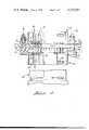
- FIG. 2is a side elevation, partly in section, of the subject pin header mounted on a printed circuit board with a mating connector exploded from one side.
- the subject snap-on pin header assemblyis comprised of first and second header members 10, 12, respectively.
- the header membersare quite similar in appearance yet have several structural differences which will be described in detail hereinbelow.
- the first header member 10is a substantially rectangular member having an elongated profiled cavity 14 opening in one surface thereof and an opposite base 16 having a plurality of pin passages 18 therein aligned to receive the respective pins of the array.
- At opposite ends of the member 10are downwardly directed mounting leg means 20, 22.
- Each of the mounting leg meanshas an outer cylindrical profile and is comprised of a pair of integral, depending leg portions 24, 26, each with an outwardly directed arcuate detent shoulder 28, 30 adjacent the free end thereof, and an axial bore 32 passing through between the leg portions 24, 26.
- the second member 12has a like outer profile with an elongated profiled cavity 34 opening in one face thereof.
- a like plurality of pin passages 36are spaced about the bottom 38 of the second member, aligned to receive the respective pins of the array, and a pair of second mounting leg means 40, 42 are at the opposite ends thereof.
- Each of the second leg meanshas a cylindrical outer profile and is made up of a pair of leg portions 44, 46 each having an outwardly directed arcuate shoulder 48, 50 on the free ends thereof.
- the legs 44, 46are dimensioned to be received through the axial bore 32 of the leg means 20, 22.
- the header members 10 and 12have profiled cavities 14, 34, respectively.
- the profiles of the cavitiesinclude polarizing and/or keying projections 52 and recesses 54 as well as apertures 56, 58 spaced from the mating face to receive therein retention lugs 60 on mating plug members 62.
- the subject header assemblyis mounted on a printed circuit board 64 that is provided with an array of pins 66 fixedly mounted therein and a pair of spaced apertures 68, 70 aligned with opposite ends of the pin array.
- the first header member 10is mounted on the board with the pins 66 being received in the appropriate apertures 18 and the leg means 20, 22 being snap fitted into the respective apertures 68, 70. It will be noted that from FIG. 2 that the first header 10 lies in intimate contact with a first surface of the printed circuit board. It should be clear that, if desired, this portion of the header assembly can be used alone.
- the second pin header 12is assembled from the opposite side of the printed circuit board with the leg means 40, 42 being inserted through the respective bores 30 of the legs 20, 22. It will be noted from FIG.
- the second header 12will be held in a stand-off position spaced from a second side of the printed circuit board. This will allow access to the pins to effect a wire wrap interconnection 72 of conductors 74 with the respective pins 66, if such is desired.
- flexure slots of the leg means of the two headersextend at right angles to one another. This serves as an anti-tangle arrangement to prevent fouling of the leg portions.
Landscapes
- Coupling Device And Connection With Printed Circuit (AREA)
- Multi-Conductor Connections (AREA)
- Printing Elements For Providing Electric Connections Between Printed Circuits (AREA)
- Structure Of Printed Boards (AREA)
Abstract
Description
1. The Field Of The Invention
The present invention relates to a header providing a protective housing around a pin array in a printed circuit board and in particular to a header that can be used to provide protection on one or both sides of the printed circuit board with a stand-off on one of the sides.
2. The Prior Art
It is well known in the electrical connector industry to provide an array of fixed pins in a printed circuit board. These pins are usually gang inserted or sequentially inserted in a first step of a manufacturing operation to utilize the circuit board. No difficulty arises in the insertion of the pins but the subsequent handling of the boards during the steps of manufacturing can cause substantial problems. Frequently the boards, with a pin array already fixed therein, are simply thrown into a stack for subsequent handling. During this rough treatment it is not an unusual occurrance to have one or more of the pins bent to a misaligned condition. It has heretofore been the common practice to have the operators visually realign the pins with such tools that are available, such as merely a pair of needle nose pliers. Such handling frequently has a delitorious effect in that the operator's untrained eye cannot accurately align the pins plus the rather crude tools can damage and/or remove plating from the pins.
The subject snap-on pin header assembly comprises a pair of housing members which can be used individually or in conjunction to form shrouds about a pin array fixedly mounted in a printed circuit board or the like. The first shroud or housing member preferably has a substantially rectangular profile with an elongated profiled cavity opening in one side thereof. At opposite ends of the housing member are a pair of mounting leg means, each formed by a pair of legs with an outwardly directed detent on the free ends of each leg and an axial through bore between the legs. The second housing member has a like outer profile with a like elongated profiled cavity opening therein and a pair of mounting leg means at the opposite ends thereof. The leg means of the second member are quite similar to those of the first member except that they are of greater length and are dimensioned to fit through the axial bores of the first leg means. Thus the second member will effectively be held in a stand-off position from a second side of a printed circuit board while the first member rests against the board.
It is therefore an object of the present invention to provide a snap-on pin header assembly which can be used to protect an array of pins fixedly mounted in a printed circuit board during subsequent processing of the circuit board.
It is another object of the present invention to produce a pin header assembly which can be snapped onto a printed circuit board to protect a pin array, which is fixedly mounted in a circuit board, from either or both sides of the board.
It is yet another object of the present invention to produce a snap-on pin header assembly which will protect the pins of a pin array mounted in a circuit board and will provide a polarized mating of a connector with the pins.
It is still another object of the present invention to produce a snap-on pin header assembly for protecting an array of pins mounted in a printed circuit board in which the header assembly will have a stand-off on one side of the board, to allow direct pin wire wrapping of the pins on that side of the board without interfering with the subsequent interconnection of a connector with the pins.
It is a further object of the present invention to produce a snap-on pin header assembly providing a retention feature for a connector plug mating with the shrouded pin array.
It is a still further object of the present invention to produce a snap-on pin header assembly which can be readily and economically manufactured.
The means for accomplishing the foregoing objects and other advantages of the present invention will be made clear to those skilled in the art from the following detailed description taken with reference to the accompanying drawings.
FIG. 1 is an exploded perspective view of the subject snap-on pin header; and
FIG. 2 is a side elevation, partly in section, of the subject pin header mounted on a printed circuit board with a mating connector exploded from one side.
The subject snap-on pin header assembly is comprised of first andsecond header members first header member 10 is a substantially rectangular member having an elongated profiledcavity 14 opening in one surface thereof and anopposite base 16 having a plurality ofpin passages 18 therein aligned to receive the respective pins of the array. At opposite ends of themember 10 are downwardly directed mounting leg means 20, 22. Each of the mounting leg means has an outer cylindrical profile and is comprised of a pair of integral, dependingleg portions detent shoulder axial bore 32 passing through between theleg portions second member 12 has a like outer profile with an elongated profiledcavity 34 opening in one face thereof. A like plurality ofpin passages 36 are spaced about thebottom 38 of the second member, aligned to receive the respective pins of the array, and a pair of second mounting leg means 40, 42 are at the opposite ends thereof. Each of the second leg means has a cylindrical outer profile and is made up of a pair ofleg portions arcuate shoulder legs axial bore 32 of the leg means 20, 22.
As mentioned above, theheader members cavities keying projections 52 andrecesses 54 as well asapertures therein retention lugs 60 onmating plug members 62.
The subject header assembly is mounted on a printedcircuit board 64 that is provided with an array ofpins 66 fixedly mounted therein and a pair of spacedapertures first header member 10 is mounted on the board with thepins 66 being received in theappropriate apertures 18 and the leg means 20, 22 being snap fitted into therespective apertures first header 10 lies in intimate contact with a first surface of the printed circuit board. It should be clear that, if desired, this portion of the header assembly can be used alone. Thesecond pin header 12 is assembled from the opposite side of the printed circuit board with the leg means 40, 42 being inserted through therespective bores 30 of thelegs shoulders second header 12 will be held in a stand-off position spaced from a second side of the printed circuit board. This will allow access to the pins to effect awire wrap interconnection 72 ofconductors 74 with therespective pins 66, if such is desired.
It should also be noted that the flexure slots of the leg means of the two headers extend at right angles to one another. This serves as an anti-tangle arrangement to prevent fouling of the leg portions.
The present invention may be subject to many modifications and changes without departing from the spirit or essential characteristics thereof. The present embodiment should therefore be considered in all respects as illustrative and not restrictive of the scope of the invention.
Claims (8)
1. A snap-on header assembly comprising:
first and second header members each having a substantially rectangular profile defining a connector receiving cavity therein,
a base of each said cavity having a plurality of pin apertures therein aligned to receive a like plurality of pins therethrough, and
mounting leg means at each end of said members, the mounting leg means of said first connector member each being defined by a pair of spaced, integral, depending leg portions having an outer arcuate profile and an inner axial bore therebetween, and an outwardly directed arcuate shoulder on the free end of each of said leg portions; and
the mounting leg means of said second member each being defined by a pair of leg portions together having an outer cylindrical profile with a slot between said leg portions and outwardly directed shoulders on the free ends thereof, said leg means of said second member being dimensioned to be received through said bores of said first leg means with the shoulders engaging on the far side thereof.
2. The snap-on pin header assembly according to claim 1 wherein at least one of said cavities is profiled to provide polarized interconnection with a mating connector member.
3. The snap-on pin header assembly according to claim 1 wherein at least one of said cavities includes an aperture in a sidewall adapted to receive therein a retention lug of a mating connector member.
4. A snap-on pin header for protecting an array of pins fixedly mounted in a printed circuit board or the like, said header comprising:
a header member of rigid insulation material having an elongated outer profile defining a profiled connector receiving cavity therein, a base of said cavity having a plurality of pin apertures therein aligned to receive a like plurality of pins therethrough, and integral mounting leg means depending from said member,
each said mounting leg means being defined by a bifurcated extension having resilient latching portions on the free ends for receipt in apertures in the circuit board and a longitudinally extending socket adapted to receive a mounting leg of another similar header mounted from the other side of said circuit board,
whereby said header member is mounted on a printed circuit board by engagement of said leg means in respective apertures in said board with the pins of the array received through said apertures and extending into said cavity to be protected by said header.
5. A snap-on pin header according to claim 4 further comprising:
a second header member of rigid insulation material having an elongated outer profile defining a profiled connector receiving cavity therein, a base of said cavity having a plurality of pin apertures therein aligned to receive a like plurality of pins therethrough, and mounting leg means at each end of said member,
said mounting leg means each being defined by a bifurcated extension having resilient latching portions on the free ends adapted to be received in said longitudinal sockets of the leg portions of said first header,
whereby said second header member is mounted on a printed circuit board on the side opposite the first header member by said second leg means being received through the sockets of said first leg means.
6. A snap-on pin header according to claim 5 wherein each said profiled cavity includes polarizing projections and recesses.
7. A snap-on header according to claim 5 wherein each said header includes apertures adapted to receive therein retention lugs of mating connector members.
8. A snap-on pin header according to claim 5 wherein said second header member is held spaced from said second side of the printed circuit board by said first leg means.
Priority Applications (4)
| Application Number | Priority Date | Filing Date | Title |
|---|---|---|---|
| US05/890,887US4173387A (en) | 1978-03-28 | 1978-03-28 | Snap-on pin header |
| EP79300328AEP0004422A3 (en) | 1978-03-28 | 1979-03-06 | Circuit board header and assembly |
| JP2883779AJPS54131774A (en) | 1978-03-28 | 1979-03-14 | Header for printed circuit board and header assembly |
| ES1979251115UES251115Y (en) | 1978-03-28 | 1979-03-23 | A HEAD TO PROTECT A GROUP OF JAS PINS. |
Applications Claiming Priority (1)
| Application Number | Priority Date | Filing Date | Title |
|---|---|---|---|
| US05/890,887US4173387A (en) | 1978-03-28 | 1978-03-28 | Snap-on pin header |
Publications (1)
| Publication Number | Publication Date |
|---|---|
| US4173387Atrue US4173387A (en) | 1979-11-06 |
Family
ID=25397281
Family Applications (1)
| Application Number | Title | Priority Date | Filing Date |
|---|---|---|---|
| US05/890,887Expired - LifetimeUS4173387A (en) | 1978-03-28 | 1978-03-28 | Snap-on pin header |
Country Status (4)
| Country | Link |
|---|---|
| US (1) | US4173387A (en) |
| EP (1) | EP0004422A3 (en) |
| JP (1) | JPS54131774A (en) |
| ES (1) | ES251115Y (en) |
Cited By (64)
| Publication number | Priority date | Publication date | Assignee | Title |
|---|---|---|---|---|
| US4295696A (en)* | 1979-12-17 | 1981-10-20 | Western Electric Company, Incorporated | Strain relief for connector wires |
| US4363530A (en)* | 1980-01-22 | 1982-12-14 | E. I. Du Pont De Nemours And Company | Spacer element for use in an electrical connector apparatus |
| US4640562A (en)* | 1984-12-19 | 1987-02-03 | Amp Incorporated | Surface mounting means for printed circuit board |
| US4659165A (en)* | 1984-11-12 | 1987-04-21 | Siemens Aktiengesellschaft | Centering strip for plugging to a backplane printed circuit board |
| US4664462A (en)* | 1985-05-20 | 1987-05-12 | Amp Incorporated | Connector receiving shroud for panel |
| US4697860A (en)* | 1986-01-29 | 1987-10-06 | Emerson Electric Co. | Insulator system for switch terminals |
| US4721470A (en)* | 1987-04-13 | 1988-01-26 | E. I. Du Pont De Nemours And Company | Keys for electrical connectors |
| US4752248A (en)* | 1987-04-24 | 1988-06-21 | Amp Incorporated | Post protector for wire wrap post terminals |
| US4761141A (en)* | 1987-03-03 | 1988-08-02 | Amp Incorporated | Locking latching shroud |
| US4781615A (en)* | 1987-08-31 | 1988-11-01 | Amp Incorporated | Cable terminating cover retention system |
| USD299715S (en) | 1985-12-04 | 1989-02-07 | Virginia Panel Corporation | High density receiver module |
| US4952529A (en)* | 1988-09-19 | 1990-08-28 | Ford Motor Company | Method of coupling a terminal to a thick film circuit board |
| US4971571A (en)* | 1990-03-15 | 1990-11-20 | Amp Incorporated | Self-locking pin field connector |
| US5080611A (en)* | 1990-12-21 | 1992-01-14 | Amp Incorporated | Boardlock for common-hole double-sided mounting |
| USD332938S (en) | 1990-11-08 | 1993-02-02 | Amp Incorporated | Electrical connector housing |
| US5217381A (en)* | 1990-09-04 | 1993-06-08 | Siemens Aktiengesellschaft | Coding mechanism having integrated special contacts for electrical assemblies pluggable onto a backplane wiring |
| US5254016A (en)* | 1992-06-17 | 1993-10-19 | Compaq Computer Corporation | Interconnect device mounting apparatus for printed circuit boards |
| US5302134A (en)* | 1991-11-04 | 1994-04-12 | Gte Products Corporation | Article locating and centering means |
| US5316487A (en)* | 1988-11-14 | 1994-05-31 | E. I. Du Pont De Nemours And Company | Spacer for board mounted connectors |
| US5490800A (en)* | 1994-07-11 | 1996-02-13 | Molex Incorporated | Electrical connector |
| US5536177A (en)* | 1994-03-18 | 1996-07-16 | The Whitaker Corporation | Set of connectors for stacked circuit board array |
| US5634810A (en)* | 1995-03-22 | 1997-06-03 | Molex Incorporated | Printed circuit board mounted electrical connector assembly |
| US5655914A (en)* | 1995-06-07 | 1997-08-12 | Samtec, Inc. | Connector having press fit mating shrouds |
| US5692912A (en)* | 1995-06-14 | 1997-12-02 | Molex Incorporated | Electrical connector with terminal tail aligning device |
| US5735697A (en)* | 1996-09-27 | 1998-04-07 | Itt Corporation | Surface mount connector |
| US5785536A (en)* | 1995-06-07 | 1998-07-28 | Santec, Inc. | Connector having press fit mating shrouds |
| US5800209A (en)* | 1993-11-12 | 1998-09-01 | Berg Technology, Inc. | Electrical connector and affixing member |
| US5807136A (en)* | 1996-05-17 | 1998-09-15 | Integrated Device Technology, Inc. | Space saving connector layout |
| US5820394A (en)* | 1995-09-28 | 1998-10-13 | Yazaki Corporation | Movable connector positioning mechanism |
| US5860823A (en)* | 1995-09-29 | 1999-01-19 | Yazaki Corporation | Movable connector with rotation limiting structure |
| US5921812A (en)* | 1997-05-03 | 1999-07-13 | Hon Hai Precision Ind. Co., Ltd. | System for mounting two connectors on two sides of board |
| US6007375A (en)* | 1997-09-05 | 1999-12-28 | Molex Incorporated | Mounting system for an electrical connector assembly |
| US6137689A (en)* | 1998-05-28 | 2000-10-24 | 3Com Corporation | Protective enclosure apparatus and method |
| US6135787A (en)* | 1998-11-03 | 2000-10-24 | Schneider Automation Inc. | Connector shroud for a pin array |
| US6231354B1 (en)* | 1998-09-23 | 2001-05-15 | The Boeing Company | System for modifying printed wiring connections after installation |
| US6237220B1 (en)* | 1998-01-16 | 2001-05-29 | Stocko Metallwarenfabriken Henkels Und Sohn Gmbh & Co. | Method for manufacturing elastic strips, pin holders and similar plug-in connectors |
| US6299478B1 (en)* | 2000-06-21 | 2001-10-09 | Hon Hai Precision Ind. Co., Ltd. | Elastic locking device for locking two components together |
| US6409538B1 (en)* | 2000-11-03 | 2002-06-25 | Cray Inc. | Electrical connector assembly for use with variable thickness circuit boards |
| US6472621B2 (en)* | 2000-03-17 | 2002-10-29 | Schneider Electric Industries Sas | Start-motor assembly |
| KR100358877B1 (en)* | 1999-06-21 | 2002-10-31 | 몰렉스 인코포레이티드 | Circuit board mounted connector assembly and method of fabricating same |
| US6743053B2 (en)* | 2002-08-09 | 2004-06-01 | Hon Hai Precision Ind. Co., Ltd. | Electrical connector with improved spacer |
| US6832934B1 (en)* | 2004-03-18 | 2004-12-21 | Hon Hai Precision Ind. Co., Ltd | High speed electrical connector |
| US20040266263A1 (en)* | 2003-06-13 | 2004-12-30 | Chih-Ming Chien | Electrical connector assembly |
| US20050106945A1 (en)* | 2003-10-03 | 2005-05-19 | Katsuhiro Suzuki | Junction connector and connection structure between wire-harnesses using the junction connector |
| US6966795B2 (en)* | 2003-05-14 | 2005-11-22 | Weco Electrical Connectors, Inc. | Surface mounted electrical component |
| US20060025005A1 (en)* | 2004-07-28 | 2006-02-02 | Olson Richard E | Pin Shroud |
| US20060084318A1 (en)* | 2004-10-18 | 2006-04-20 | Jason Si | Double-side mounting electrical connector |
| US20060234524A1 (en)* | 2003-04-28 | 2006-10-19 | Valeo Equipements Electriques Moteur | Interposed electrical connector which is intended to connect two stacked electronic circuits and to the method of mounting same |
| US20070155206A1 (en)* | 2006-01-05 | 2007-07-05 | Hon Hai Precision Ind. Co., Ltd. | Electrical connector assembly with cover |
| US20070224850A1 (en)* | 2006-03-21 | 2007-09-27 | Erni-Elektro-Apparate Gmbh | Plug connection adapter |
| US20080207053A1 (en)* | 2007-02-26 | 2008-08-28 | Chih-Ming Lin | USB connector housing |
| US20090111293A1 (en)* | 2007-10-29 | 2009-04-30 | Brandon Rubenstein | Retractable protection apparatus for electronic device pins |
| US20110244735A1 (en)* | 2010-03-31 | 2011-10-06 | Hon Hai Precision Industry Co., Ltd. | Electrical connector having deformable engaging post |
| US20120129373A1 (en)* | 2010-11-18 | 2012-05-24 | Tyco Electronics Corporation | Electrical connector assembly having connector shroud |
| CN102683925A (en)* | 2011-03-14 | 2012-09-19 | 鸿富锦精密工业(深圳)有限公司 | Board to board connector and manufacturing method thereof |
| CN103457075A (en)* | 2012-05-30 | 2013-12-18 | 鸿富锦精密工业(深圳)有限公司 | Connector protection cover |
| US20140140665A1 (en)* | 2012-11-16 | 2014-05-22 | Oclaro Japan, Inc. | Optical module and optical transceiver |
| US20170110814A1 (en)* | 2015-10-19 | 2017-04-20 | Sumitomo Wiring Systems, Ltd. | Board connector |
| US9912108B2 (en)* | 2015-06-15 | 2018-03-06 | Tyco Electronics Japan G.K. | Electrical connector |
| US10297966B1 (en)* | 2018-01-15 | 2019-05-21 | Te Connectivity Corporation | Mating adapter for an electrical connector assembly |
| CN111180926A (en)* | 2018-11-12 | 2020-05-19 | 泰科电子(上海)有限公司 | Electric connector, electric connector assembly and electric assembly |
| CN115882303A (en)* | 2023-01-31 | 2023-03-31 | 北京元隆雅图文化传播股份有限公司 | Power strip type tool and connector mounting structure |
| US20230216247A1 (en)* | 2020-04-20 | 2023-07-06 | Latelec | Improved fool-proofing device, electrical connection assembly comprising said improved fool-proofing device and associated assembly method |
| WO2025098633A1 (en)* | 2023-11-10 | 2025-05-15 | Harting International Innovation AG | Socket housing |
Families Citing this family (10)
| Publication number | Priority date | Publication date | Assignee | Title |
|---|---|---|---|---|
| US4489998A (en)* | 1982-11-01 | 1984-12-25 | Amp Incorporated | Bussing connector system |
| US4490000A (en)* | 1983-03-23 | 1984-12-25 | Amp Incorporated | Multi-plane crossover contact |
| US4550960A (en)* | 1984-08-24 | 1985-11-05 | Amp Incorporated | Shielded backplane assembly |
| EP0225336A1 (en)* | 1985-05-20 | 1987-06-16 | AMP INCORPORATED (a New Jersey corporation) | Connector receiving shroud for panel |
| DE8515249U1 (en)* | 1985-05-23 | 1985-07-11 | Nixdorf Computer Ag, 4790 Paderborn | Frame part for a contact element strip of a plug connection |
| JPS62175583U (en)* | 1986-04-25 | 1987-11-07 | ||
| JPH07106033A (en)* | 1993-09-30 | 1995-04-21 | Sumitomo Wiring Syst Ltd | Standby connector |
| DE4431198C2 (en)* | 1994-09-02 | 1996-12-19 | Krone Ag | Insulation displacement contact element for the electrical contacting of printed circuit boards |
| CN105485117B (en)* | 2016-01-26 | 2018-06-01 | 上海磊跃自动化设备有限公司 | A kind of connector that can be concatenated from beginning to end |
| JP7288410B2 (en)* | 2020-02-18 | 2023-06-07 | ヒロセ電機株式会社 | Relay electrical connector, electrical connector assembly and electrical connector assembly with circuit board |
Citations (6)
| Publication number | Priority date | Publication date | Assignee | Title |
|---|---|---|---|---|
| US3394337A (en)* | 1966-08-15 | 1968-07-23 | Hughes Aircraft Co | Connector securing device |
| US3500288A (en)* | 1967-05-20 | 1970-03-10 | Amp Inc | Printed circuit connector with resiliently mounted contacts |
| US3568001A (en)* | 1969-04-08 | 1971-03-02 | Sam Straus | Snap-on board mating contact system |
| US3950060A (en)* | 1974-10-29 | 1976-04-13 | Molex Incorporated | Connector assembly |
| US4053199A (en)* | 1975-03-05 | 1977-10-11 | Amp Incorporated | Cable connectable bulkhead filter array |
| US4068915A (en)* | 1975-09-22 | 1978-01-17 | E. I. Du Pont De Nemours And Company | Electrical connector |
Family Cites Families (7)
| Publication number | Priority date | Publication date | Assignee | Title |
|---|---|---|---|---|
| US2439744A (en)* | 1945-12-15 | 1948-04-13 | Simplex Time Recorder Co | Plug and jack assembly |
| GB657458A (en)* | 1949-02-21 | 1951-09-19 | Horatio Henry Burtt | A self-separating electrical pin and socket connector |
| US3004238A (en)* | 1961-01-27 | 1961-10-10 | Raytheon Co | Detachable electrical connectors and attaching means therefor |
| FR2199245B1 (en)* | 1972-09-08 | 1981-08-07 | Souriau & Cie | |
| DE7247105U (en)* | 1972-12-23 | 1973-04-26 | Dornier System Gmbh | PLUG FASTENING |
| FR2237332A1 (en)* | 1973-07-02 | 1975-02-07 | Doloise Metallurgique | Printed circuit connector mounting device - self tapping bolt passes through support and engages in split bor |
| BR7504570A (en)* | 1974-08-23 | 1976-08-03 | Thomas & Betts Corp | IMPROVEMENT IN CONNECTOR TO CONNECT INDIVIDUAL CONDUCTORS OF A MULTICONDUCTOR FLAT CABLE |
- 1978
- 1978-03-28USUS05/890,887patent/US4173387A/ennot_activeExpired - Lifetime
- 1979
- 1979-03-06EPEP79300328Apatent/EP0004422A3/ennot_activeWithdrawn
- 1979-03-14JPJP2883779Apatent/JPS54131774A/enactivePending
- 1979-03-23ESES1979251115Upatent/ES251115Y/ennot_activeExpired
Patent Citations (6)
| Publication number | Priority date | Publication date | Assignee | Title |
|---|---|---|---|---|
| US3394337A (en)* | 1966-08-15 | 1968-07-23 | Hughes Aircraft Co | Connector securing device |
| US3500288A (en)* | 1967-05-20 | 1970-03-10 | Amp Inc | Printed circuit connector with resiliently mounted contacts |
| US3568001A (en)* | 1969-04-08 | 1971-03-02 | Sam Straus | Snap-on board mating contact system |
| US3950060A (en)* | 1974-10-29 | 1976-04-13 | Molex Incorporated | Connector assembly |
| US4053199A (en)* | 1975-03-05 | 1977-10-11 | Amp Incorporated | Cable connectable bulkhead filter array |
| US4068915A (en)* | 1975-09-22 | 1978-01-17 | E. I. Du Pont De Nemours And Company | Electrical connector |
Cited By (77)
| Publication number | Priority date | Publication date | Assignee | Title |
|---|---|---|---|---|
| US4295696A (en)* | 1979-12-17 | 1981-10-20 | Western Electric Company, Incorporated | Strain relief for connector wires |
| US4363530A (en)* | 1980-01-22 | 1982-12-14 | E. I. Du Pont De Nemours And Company | Spacer element for use in an electrical connector apparatus |
| US4659165A (en)* | 1984-11-12 | 1987-04-21 | Siemens Aktiengesellschaft | Centering strip for plugging to a backplane printed circuit board |
| US4640562A (en)* | 1984-12-19 | 1987-02-03 | Amp Incorporated | Surface mounting means for printed circuit board |
| US4664462A (en)* | 1985-05-20 | 1987-05-12 | Amp Incorporated | Connector receiving shroud for panel |
| USD299715S (en) | 1985-12-04 | 1989-02-07 | Virginia Panel Corporation | High density receiver module |
| US4697860A (en)* | 1986-01-29 | 1987-10-06 | Emerson Electric Co. | Insulator system for switch terminals |
| US4761141A (en)* | 1987-03-03 | 1988-08-02 | Amp Incorporated | Locking latching shroud |
| US4721470A (en)* | 1987-04-13 | 1988-01-26 | E. I. Du Pont De Nemours And Company | Keys for electrical connectors |
| US4752248A (en)* | 1987-04-24 | 1988-06-21 | Amp Incorporated | Post protector for wire wrap post terminals |
| US4781615A (en)* | 1987-08-31 | 1988-11-01 | Amp Incorporated | Cable terminating cover retention system |
| US4952529A (en)* | 1988-09-19 | 1990-08-28 | Ford Motor Company | Method of coupling a terminal to a thick film circuit board |
| US5316487A (en)* | 1988-11-14 | 1994-05-31 | E. I. Du Pont De Nemours And Company | Spacer for board mounted connectors |
| US4971571A (en)* | 1990-03-15 | 1990-11-20 | Amp Incorporated | Self-locking pin field connector |
| US5217381A (en)* | 1990-09-04 | 1993-06-08 | Siemens Aktiengesellschaft | Coding mechanism having integrated special contacts for electrical assemblies pluggable onto a backplane wiring |
| USD332938S (en) | 1990-11-08 | 1993-02-02 | Amp Incorporated | Electrical connector housing |
| US5080611A (en)* | 1990-12-21 | 1992-01-14 | Amp Incorporated | Boardlock for common-hole double-sided mounting |
| US5302134A (en)* | 1991-11-04 | 1994-04-12 | Gte Products Corporation | Article locating and centering means |
| US5312264A (en)* | 1991-11-04 | 1994-05-17 | Gte Products Corp. | Article locating and centering means |
| US5254016A (en)* | 1992-06-17 | 1993-10-19 | Compaq Computer Corporation | Interconnect device mounting apparatus for printed circuit boards |
| US5800209A (en)* | 1993-11-12 | 1998-09-01 | Berg Technology, Inc. | Electrical connector and affixing member |
| US5536177A (en)* | 1994-03-18 | 1996-07-16 | The Whitaker Corporation | Set of connectors for stacked circuit board array |
| US5490800A (en)* | 1994-07-11 | 1996-02-13 | Molex Incorporated | Electrical connector |
| US5634810A (en)* | 1995-03-22 | 1997-06-03 | Molex Incorporated | Printed circuit board mounted electrical connector assembly |
| US5785536A (en)* | 1995-06-07 | 1998-07-28 | Santec, Inc. | Connector having press fit mating shrouds |
| US5655914A (en)* | 1995-06-07 | 1997-08-12 | Samtec, Inc. | Connector having press fit mating shrouds |
| US5692912A (en)* | 1995-06-14 | 1997-12-02 | Molex Incorporated | Electrical connector with terminal tail aligning device |
| US5947759A (en)* | 1995-09-28 | 1999-09-07 | Yazaki Corporation | Movable connector positioning mechanism |
| US5820394A (en)* | 1995-09-28 | 1998-10-13 | Yazaki Corporation | Movable connector positioning mechanism |
| US5860823A (en)* | 1995-09-29 | 1999-01-19 | Yazaki Corporation | Movable connector with rotation limiting structure |
| US5807136A (en)* | 1996-05-17 | 1998-09-15 | Integrated Device Technology, Inc. | Space saving connector layout |
| US5735697A (en)* | 1996-09-27 | 1998-04-07 | Itt Corporation | Surface mount connector |
| US5921812A (en)* | 1997-05-03 | 1999-07-13 | Hon Hai Precision Ind. Co., Ltd. | System for mounting two connectors on two sides of board |
| US6007375A (en)* | 1997-09-05 | 1999-12-28 | Molex Incorporated | Mounting system for an electrical connector assembly |
| US6237220B1 (en)* | 1998-01-16 | 2001-05-29 | Stocko Metallwarenfabriken Henkels Und Sohn Gmbh & Co. | Method for manufacturing elastic strips, pin holders and similar plug-in connectors |
| US6137689A (en)* | 1998-05-28 | 2000-10-24 | 3Com Corporation | Protective enclosure apparatus and method |
| US6231354B1 (en)* | 1998-09-23 | 2001-05-15 | The Boeing Company | System for modifying printed wiring connections after installation |
| EP0989631B1 (en)* | 1998-09-23 | 2005-11-02 | The Boeing Company | System for modifying printed wiring connections after installation |
| US6135787A (en)* | 1998-11-03 | 2000-10-24 | Schneider Automation Inc. | Connector shroud for a pin array |
| KR100358877B1 (en)* | 1999-06-21 | 2002-10-31 | 몰렉스 인코포레이티드 | Circuit board mounted connector assembly and method of fabricating same |
| US6472621B2 (en)* | 2000-03-17 | 2002-10-29 | Schneider Electric Industries Sas | Start-motor assembly |
| US6299478B1 (en)* | 2000-06-21 | 2001-10-09 | Hon Hai Precision Ind. Co., Ltd. | Elastic locking device for locking two components together |
| US6409538B1 (en)* | 2000-11-03 | 2002-06-25 | Cray Inc. | Electrical connector assembly for use with variable thickness circuit boards |
| US6743053B2 (en)* | 2002-08-09 | 2004-06-01 | Hon Hai Precision Ind. Co., Ltd. | Electrical connector with improved spacer |
| US20060234524A1 (en)* | 2003-04-28 | 2006-10-19 | Valeo Equipements Electriques Moteur | Interposed electrical connector which is intended to connect two stacked electronic circuits and to the method of mounting same |
| US7241149B2 (en)* | 2003-04-28 | 2007-07-10 | Valeo Equipments Electriques Moteur | Interposed electrical connector which is intended to connect two stacked electronic circuits and to the method of mounting same |
| US6966795B2 (en)* | 2003-05-14 | 2005-11-22 | Weco Electrical Connectors, Inc. | Surface mounted electrical component |
| US20040266263A1 (en)* | 2003-06-13 | 2004-12-30 | Chih-Ming Chien | Electrical connector assembly |
| US6948979B2 (en)* | 2003-06-13 | 2005-09-27 | Hon Hai Precision Ind. Co., Ltd. | Electrical connector assembly |
| US20050106945A1 (en)* | 2003-10-03 | 2005-05-19 | Katsuhiro Suzuki | Junction connector and connection structure between wire-harnesses using the junction connector |
| US6832934B1 (en)* | 2004-03-18 | 2004-12-21 | Hon Hai Precision Ind. Co., Ltd | High speed electrical connector |
| US7273386B2 (en) | 2004-07-28 | 2007-09-25 | Hewlett-Packard Development Company, L.P. | Pin shroud |
| US20060025005A1 (en)* | 2004-07-28 | 2006-02-02 | Olson Richard E | Pin Shroud |
| US20060084318A1 (en)* | 2004-10-18 | 2006-04-20 | Jason Si | Double-side mounting electrical connector |
| US20070155206A1 (en)* | 2006-01-05 | 2007-07-05 | Hon Hai Precision Ind. Co., Ltd. | Electrical connector assembly with cover |
| US20070224850A1 (en)* | 2006-03-21 | 2007-09-27 | Erni-Elektro-Apparate Gmbh | Plug connection adapter |
| US7410368B2 (en)* | 2006-03-21 | 2008-08-12 | Erni Electronics Gmbh | Plug connection adapter |
| US20080207053A1 (en)* | 2007-02-26 | 2008-08-28 | Chih-Ming Lin | USB connector housing |
| US20090111293A1 (en)* | 2007-10-29 | 2009-04-30 | Brandon Rubenstein | Retractable protection apparatus for electronic device pins |
| US7544072B2 (en) | 2007-10-29 | 2009-06-09 | Hewlett-Packard Development Company, L.P. | Retractable protection apparatus for electronic device pins |
| US20110244735A1 (en)* | 2010-03-31 | 2011-10-06 | Hon Hai Precision Industry Co., Ltd. | Electrical connector having deformable engaging post |
| US8221170B2 (en)* | 2010-03-31 | 2012-07-17 | Hon Hai Precision Ind. Co., Ltd. | Electrical connector having deformable engaging post |
| US8784132B2 (en)* | 2010-11-18 | 2014-07-22 | Tyco Electronics Corporation | Electrical connector assembly having connector shroud |
| US20120129373A1 (en)* | 2010-11-18 | 2012-05-24 | Tyco Electronics Corporation | Electrical connector assembly having connector shroud |
| CN102683925B (en)* | 2011-03-14 | 2015-04-01 | 鸿富锦精密工业(深圳)有限公司 | Board-to-board connector and manufacturing method thereof |
| CN102683925A (en)* | 2011-03-14 | 2012-09-19 | 鸿富锦精密工业(深圳)有限公司 | Board to board connector and manufacturing method thereof |
| CN103457075A (en)* | 2012-05-30 | 2013-12-18 | 鸿富锦精密工业(深圳)有限公司 | Connector protection cover |
| US20140140665A1 (en)* | 2012-11-16 | 2014-05-22 | Oclaro Japan, Inc. | Optical module and optical transceiver |
| US9912108B2 (en)* | 2015-06-15 | 2018-03-06 | Tyco Electronics Japan G.K. | Electrical connector |
| US20170110814A1 (en)* | 2015-10-19 | 2017-04-20 | Sumitomo Wiring Systems, Ltd. | Board connector |
| US9859633B2 (en)* | 2015-10-19 | 2018-01-02 | Sumitomo Wiring Systems, Ltd. | Board connector |
| US10297966B1 (en)* | 2018-01-15 | 2019-05-21 | Te Connectivity Corporation | Mating adapter for an electrical connector assembly |
| CN111180926A (en)* | 2018-11-12 | 2020-05-19 | 泰科电子(上海)有限公司 | Electric connector, electric connector assembly and electric assembly |
| US20230216247A1 (en)* | 2020-04-20 | 2023-07-06 | Latelec | Improved fool-proofing device, electrical connection assembly comprising said improved fool-proofing device and associated assembly method |
| US12300935B2 (en)* | 2020-04-20 | 2025-05-13 | Latelec | Fool-proofing device, electrical connection assembly comprising said improved fool-proofing device and associated assembly method |
| CN115882303A (en)* | 2023-01-31 | 2023-03-31 | 北京元隆雅图文化传播股份有限公司 | Power strip type tool and connector mounting structure |
| WO2025098633A1 (en)* | 2023-11-10 | 2025-05-15 | Harting International Innovation AG | Socket housing |
Also Published As
| Publication number | Publication date |
|---|---|
| JPS54131774A (en) | 1979-10-13 |
| ES251115Y (en) | 1981-03-16 |
| ES251115U (en) | 1980-09-16 |
| EP0004422A3 (en) | 1979-10-31 |
| EP0004422A2 (en) | 1979-10-03 |
Similar Documents
| Publication | Publication Date | Title |
|---|---|---|
| US4173387A (en) | Snap-on pin header | |
| US4168877A (en) | Single lever back plane connector system | |
| CA1169511A (en) | Cover for multiple terminal electrical connector | |
| EP0749182B1 (en) | Electrical connector with terminal tail aligning device | |
| US6071152A (en) | Electrical connector with inserted terminals | |
| US4428636A (en) | Multi-contact connectors for closely spaced conductors | |
| US5080611A (en) | Boardlock for common-hole double-sided mounting | |
| EP0105723B1 (en) | A connector for shielded cable | |
| EP0386742B1 (en) | Electrical connector with socket contacts of different sizes having means for preventing erroneous connection | |
| US8568157B2 (en) | Cap body insulation displacement connector (IDC) | |
| US4560226A (en) | Electrical connector member and contactor unit | |
| US4212510A (en) | Filtered header | |
| US5310360A (en) | Circuit board mounted modular phone jack | |
| US6045389A (en) | Contact and connector for terminating a pair of individually insulated wires | |
| US5326286A (en) | Electrical connector assembly with terminal alignment system | |
| EP0624928B1 (en) | Shielded electrical connector assembly | |
| US4557543A (en) | Key hole retention | |
| WO1986000473A1 (en) | Printed circuit board header having coaxial sockets therein and matable coaxial plug housing | |
| US4367004A (en) | Electrical connector | |
| US3523273A (en) | Electrical connectors | |
| US4475786A (en) | T Bar cover latch | |
| US4886942A (en) | Strain relief structure for connecting flat flexible cable to a circuit board | |
| EP0856922B1 (en) | Board straddle mounted electrical connector | |
| US5425660A (en) | Communications jack with improved comb | |
| EP0717473B1 (en) | Electrical pin field on a printed circuit board |