US4172709A - Bacteria filters with transparent housings - Google Patents
Bacteria filters with transparent housingsDownload PDFInfo
- Publication number
- US4172709A US4172709AUS05/907,900US90790078AUS4172709AUS 4172709 AUS4172709 AUS 4172709AUS 90790078 AUS90790078 AUS 90790078AUS 4172709 AUS4172709 AUS 4172709A
- Authority
- US
- United States
- Prior art keywords
- housing
- filter
- connector
- conductive
- end cap
- Prior art date
- Legal status (The legal status is an assumption and is not a legal conclusion. Google has not performed a legal analysis and makes no representation as to the accuracy of the status listed.)
- Expired - Lifetime
Links
- 241000894006BacteriaSpecies0.000titleclaimsabstractdescription5
- 239000012530fluidSubstances0.000claimsabstractdescription18
- 230000000241respiratory effectEffects0.000claimsabstractdescription6
- 238000004891communicationMethods0.000claimsabstractdescription4
- 230000037361pathwayEffects0.000claimsabstractdescription4
- 239000004020conductorSubstances0.000claimsdescription12
- 230000000717retained effectEffects0.000abstractdescription2
- 239000007789gasSubstances0.000description18
- 230000029058respiratory gaseous exchangeEffects0.000description15
- 101000793686Homo sapiens AzurocidinProteins0.000description7
- 239000000463materialSubstances0.000description7
- 239000006096absorbing agentSubstances0.000description6
- QVGXLLKOCUKJST-UHFFFAOYSA-Natomic oxygenChemical compound[O]QVGXLLKOCUKJST-UHFFFAOYSA-N0.000description6
- 238000001914filtrationMethods0.000description6
- 239000001301oxygenSubstances0.000description6
- 229910052760oxygenInorganic materials0.000description6
- 238000013461designMethods0.000description5
- 206010002091AnaesthesiaDiseases0.000description4
- 230000037005anaesthesiaEffects0.000description4
- 239000006200vaporizerSubstances0.000description4
- 238000000034methodMethods0.000description3
- CURLTUGMZLYLDI-UHFFFAOYSA-NCarbon dioxideChemical compoundO=C=OCURLTUGMZLYLDI-UHFFFAOYSA-N0.000description2
- RTZKZFJDLAIYFH-UHFFFAOYSA-NDiethyl etherChemical compoundCCOCCRTZKZFJDLAIYFH-UHFFFAOYSA-N0.000description2
- 239000004593EpoxySubstances0.000description2
- GQPLMRYTRLFLPF-UHFFFAOYSA-NNitrous OxideChemical compound[O-][N+]#NGQPLMRYTRLFLPF-UHFFFAOYSA-N0.000description2
- 229940035674anestheticsDrugs0.000description2
- 238000009833condensationMethods0.000description2
- 230000005494condensationEffects0.000description2
- 229940079593drugDrugs0.000description2
- 239000003814drugSubstances0.000description2
- 239000003193general anesthetic agentSubstances0.000description2
- BCQZXOMGPXTTIC-UHFFFAOYSA-NhalothaneChemical compoundFC(F)(F)C(Cl)BrBCQZXOMGPXTTIC-UHFFFAOYSA-N0.000description2
- 229960003132halothaneDrugs0.000description2
- 238000002483medicationMethods0.000description2
- 239000004033plasticSubstances0.000description2
- LVZWSLJZHVFIQJ-UHFFFAOYSA-NCyclopropaneChemical compoundC1CC1LVZWSLJZHVFIQJ-UHFFFAOYSA-N0.000description1
- IAYPIBMASNFSPL-UHFFFAOYSA-NEthylene oxideChemical compoundC1CO1IAYPIBMASNFSPL-UHFFFAOYSA-N0.000description1
- 238000010521absorption reactionMethods0.000description1
- 238000009825accumulationMethods0.000description1
- 239000000853adhesiveSubstances0.000description1
- 230000001070adhesive effectEffects0.000description1
- 239000003570airSubstances0.000description1
- 229910002092carbon dioxideInorganic materials0.000description1
- 239000001569carbon dioxideSubstances0.000description1
- 239000003795chemical substances by applicationSubstances0.000description1
- 239000011248coating agentSubstances0.000description1
- 238000000576coating methodMethods0.000description1
- 238000011161developmentMethods0.000description1
- 229940035423ethyl etherDrugs0.000description1
- PCHJSUWPFVWCPO-UHFFFAOYSA-NgoldChemical compound[Au]PCHJSUWPFVWCPO-UHFFFAOYSA-N0.000description1
- 239000010931goldSubstances0.000description1
- 229910052737goldInorganic materials0.000description1
- 239000007788liquidSubstances0.000description1
- RFKMCNOHBTXSMU-UHFFFAOYSA-NmethoxyfluraneChemical compoundCOC(F)(F)C(Cl)ClRFKMCNOHBTXSMU-UHFFFAOYSA-N0.000description1
- 229960002455methoxyfluraneDrugs0.000description1
- XMSZANIMCDLNKA-UHFFFAOYSA-Nmethyl hypofluoriteChemical compoundCOFXMSZANIMCDLNKA-UHFFFAOYSA-N0.000description1
- 239000000203mixtureSubstances0.000description1
- 238000012544monitoring processMethods0.000description1
- 229960001730nitrous oxideDrugs0.000description1
- 239000001272nitrous oxideSubstances0.000description1
- 239000012811non-conductive materialSubstances0.000description1
- 239000002245particleSubstances0.000description1
- 230000000737periodic effectEffects0.000description1
- ISWSIDIOOBJBQZ-UHFFFAOYSA-Nphenol groupChemical groupC1(=CC=CC=C1)OISWSIDIOOBJBQZ-UHFFFAOYSA-N0.000description1
- 239000012858resilient materialSubstances0.000description1
- 230000000284resting effectEffects0.000description1
- 229920006395saturated elastomerPolymers0.000description1
- 230000001954sterilising effectEffects0.000description1
- 238000004659sterilization and disinfectionMethods0.000description1
- 239000000126substanceSubstances0.000description1
- 239000012780transparent materialSubstances0.000description1
- XLYOFNOQVPJJNP-UHFFFAOYSA-NwaterSubstancesOXLYOFNOQVPJJNP-UHFFFAOYSA-N0.000description1
- 238000004078waterproofingMethods0.000description1
Images


Classifications
- B—PERFORMING OPERATIONS; TRANSPORTING
- B01—PHYSICAL OR CHEMICAL PROCESSES OR APPARATUS IN GENERAL
- B01D—SEPARATION
- B01D46/00—Filters or filtering processes specially modified for separating dispersed particles from gases or vapours
- B01D46/0027—Filters or filtering processes specially modified for separating dispersed particles from gases or vapours with additional separating or treating functions
- B01D46/0028—Filters or filtering processes specially modified for separating dispersed particles from gases or vapours with additional separating or treating functions provided with antibacterial or antifungal means
- A—HUMAN NECESSITIES
- A61—MEDICAL OR VETERINARY SCIENCE; HYGIENE
- A61M—DEVICES FOR INTRODUCING MEDIA INTO, OR ONTO, THE BODY; DEVICES FOR TRANSDUCING BODY MEDIA OR FOR TAKING MEDIA FROM THE BODY; DEVICES FOR PRODUCING OR ENDING SLEEP OR STUPOR
- A61M16/00—Devices for influencing the respiratory system of patients by gas treatment, e.g. ventilators; Tracheal tubes
- A61M16/10—Preparation of respiratory gases or vapours
- A61M16/105—Filters
- A61M16/1055—Filters bacterial
- A—HUMAN NECESSITIES
- A62—LIFE-SAVING; FIRE-FIGHTING
- A62B—DEVICES, APPARATUS OR METHODS FOR LIFE-SAVING
- A62B23/00—Filters for breathing-protection purposes
- A62B23/02—Filters for breathing-protection purposes for respirators
- B—PERFORMING OPERATIONS; TRANSPORTING
- B01—PHYSICAL OR CHEMICAL PROCESSES OR APPARATUS IN GENERAL
- B01D—SEPARATION
- B01D46/00—Filters or filtering processes specially modified for separating dispersed particles from gases or vapours
- B01D46/0002—Casings; Housings; Frame constructions
- B01D46/0012—In-line filters
- B—PERFORMING OPERATIONS; TRANSPORTING
- B01—PHYSICAL OR CHEMICAL PROCESSES OR APPARATUS IN GENERAL
- B01D—SEPARATION
- B01D46/00—Filters or filtering processes specially modified for separating dispersed particles from gases or vapours
- B01D46/0084—Filters or filtering processes specially modified for separating dispersed particles from gases or vapours provided with safety means
- B01D46/0091—Including arrangements for environmental or personal protection
- B—PERFORMING OPERATIONS; TRANSPORTING
- B01—PHYSICAL OR CHEMICAL PROCESSES OR APPARATUS IN GENERAL
- B01D—SEPARATION
- B01D46/00—Filters or filtering processes specially modified for separating dispersed particles from gases or vapours
- B01D46/24—Particle separators, e.g. dust precipitators, using rigid hollow filter bodies
- B—PERFORMING OPERATIONS; TRANSPORTING
- B01—PHYSICAL OR CHEMICAL PROCESSES OR APPARATUS IN GENERAL
- B01D—SEPARATION
- B01D46/00—Filters or filtering processes specially modified for separating dispersed particles from gases or vapours
- B01D46/42—Auxiliary equipment or operation thereof
- B01D46/4254—Allowing or improving visual supervision, e.g. lamps, transparent parts, windows
Definitions
- filtersfor the environment under consideration is that they are generally designed to interconnect with a system of a predetermined arrangement. It would be extremely advantageous to provide a filter which is adaptable for connection with a variety of different types of breathing systems without altering the physical structure of the filter itself.
- the filterbe of low cost disposable materials so as to be compatible with general systems presently in use which are primarily designed for single use.
- the filtershould be versatile enough so that the condensate build-up can be removed during the single use without the necessity of having to use a multiple of filters for an individual patient.
- the filteris adapted to receive fluid flow therethrough in either axial direction, contains a conductive path from end to end to alleviate electrical dangers, includes a transparent housing to permit the observation of condensate build-up within the filter during use, and contains a valve mechanism on the filter to drain condensate which has built up beyond a desirable level within the filter during use thereby alleviating the necessity of use of multiple filters for a single patient.
- the provision of a conductive path along with the transparent housing to permit observation of condensate build-up and the valve to drain excessive condensatecombine to alleviate well known patient safety hazards.
- a bacteria filterfor use in anesthesiology and respiratory care systems to filter fluid flow at a desired point in the system.
- the filterincludes an enlarged non-conductive, transparent tubular housing having a passageway therethrough and tapering at one end to a reduced tip.
- a conductive connectoris mounted to the reduced tip and a conductive end cap is affixed to the end of the housing distal from the reduced tip.
- the end caphas an opening therethrough terminating in a projecting connector.
- a filter elementis retained in the housing and a conductive portion extends between the end cap and the conductive connector to provide a conductive pathway from end to end of the filter.
- the connector and the projecting connectorare adapted to be mounted within a fluid flow system to permit fluid communication with the interior of the housing so that fluid flow through the system passes in one end of the housing, through the filter element and out the other end.
- FIG. 1is a schematic view of the filter of the invention in operable position within a representative anesthesia breathing circuit
- FIG. 2is a sectional elevation view of the filter of the invention
- FIG. 3is a cross-sectional view of the filter taken along the plane of line 3--3 of FIG. 2;
- FIG. 4is a cross-sectional view of the filter taken along the plane of line 4--4 of FIG. 2;
- FIG. 5is a cross sectional view of an alternative form of the filter of the invention.
- FIG. 6is a cross sectional view of a second alternative form of the filter of the invention.
- FIG. 7is an end sectional view thereof taken along the plane of line 7--7 of FIG. 6;
- FIG. 8is a cross sectional view of a third alternative form of the filter of the invention.
- FIG. 9is an end sectional view thereof taken along the plane of line 9--9 of FIG. 8;
- FIG. 10is a plan view of a fourth alternative form of the filter of the invention.
- FIG. 11is a cross sectional view of a fifth alternative form of the filter of the invention.
- Filter 20is depicted independently in FIGS. 2, 3 and 4 and is shown in cooperation within a conventional well known type of anesthesia breathing circuit 21 in FIG. 1.
- Filter 20is adapted to pass flow therethrough in either direction and is open at both ends.
- One end of filter 20is connected to a corrugated conduit 22 which passes directly to a patient breathing mechanism 23.
- the other end of filter 20is connected in line to a source of gases for filtering prior to introduction to the patient.
- the gasesmay originate in part from an exhalation conduit 24 passing from the breathing mechanism 23 and entering through a check valve into a breathing bag 25.
- the exhalation gasesthen pass from breathing bag 25 into an absorber apparatus 26 for absorption of liquid to enhance the gases for reception by the patient.
- valve engaging apparatussuch as pressure relief valve 27, exhalation check valve assembly 28, and pressure gauge 29.
- Appropriate conduit meansare provided to guide the gases from the breathing bag to the absorber apparatus as monitored by valves and gauges as discussed above.
- An inlet 32is provided along conduit 31 for introduction of fresh gas to be mixed with the gas from the absorber apparatus 26.
- the mixtureis then vaporized in a well known manner in vaporizer 30 and is passed from the vaporizer 30 to the filter 20 for filtering prior to introduction through conduit 22 and breathing device 23 to the patient.
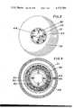
- an enlarged tubular housing 31is provided with openings at both ends. At one end the housing tapers at portion 32 until it terminates in an annular reduced tip 33. An internal rib extends inwardly from the inner surface of reduced tip 33 for interlocking with a conductive connector 35.
- the other end of enlarged tubular housing 31contains an annular rib 36 adjacent its end for facilitating interengagement with a conductive end cap 37.
- a projecting connector portion 38which is tubular in configuration and open at both ends extends from a central location from end cap 37 away from housing 31.
- End cap 37has a plurality of concentric ribs extending inwardly of housing 31 with the outer rib 39 having appropriate detent to interengage with rib 36 of housing 31 and thereby lock the end cap to the housing.
- the inner two concentric ribs 40form an annular recess 41 for reception of one end of a filter element 42.
- the filter elementis hollow and cylindrical in configuration.
- Housing 31is of a transparent non-conductive material of plastic or other conventional material having the similar properties.
- conductive connector 35 and end cap 37 including projecting connector 38are of an electrically conductive material.
- the materialmay be plastic or other well known conventional substance having similar properties.
- Projection 38 and connector 35need not be transparent in nature as long as enlarged housing 31 is transparent so that the interior chamber 43 thereof can be observed at all times during operation of the filter.
- Both ends of filter 20are conductive in nature in the form of connector 35 and projecting connector 38 and in order to provide a conductive path throughout the entire length of filter 20, it is necessary to provide an intermediate portion of conductive material extending between connector 35 and connector 38.
- Thismay take the form of a strip of material along the length of housing 31 on the exterior surface thereof and interconnected at its ends with connector 35 and connector 38. The strip may be fastened to the outer surface of housing 31 by means of an adhesive or other conventional means.
- the conductive portioncan be a finned element 44 extending axially through the interior of housing 31 and interengaging with connector 35 and connector 38 at each respective end.
- the plurality of fins 45 on finned element 44are spaced circumferentially apart so as to increase the contact points and assure a continuous conductive path from connector 38 through housing 31 to connector 35.
- a circular tray 46Intermediate the ends of the finned element 44 is a circular tray 46 with an appropriate annular recess 47.
- Recess 47is in alignment with recess 41 on the interior surface of end cap 37.
- the two recesses 47 and 41receive opposed ends of hollow tubular filter element 42 and thereby mount the filter element within housing 31 for use.
- Connector 35has an outer surface configuration which facilitates its use as a male connector for introduction within an appropriate conduit of a breathing system.
- connector 38is provided with inner and outer surfaces so that it is adapted to receive a male connector element of a breathing system.
- one end of the filteris formed as a male connector element and the other end of the filter is formed as a female connector element. Fluid flow can proceed in either direction through filter 20 and, accordingly, connectors 38 and 35 are interchangeable thereby adding to the versatility of filter 20 for interconnection within a breathing system.
- end wall of end cap 37is also provided with an aperture 48 therethrough to provide communication between the exterior of the filter and the interior of chamber 43.
- a plug 49which seals with the walls forming the aperture to prevent fluid flow into or out of the filter.
- a gripping portion 50extends rearwardly from end cap 37 and exteriorly of housing 31. Consequently, plug 49 can be removed from aperture 48 by grasping portion 50 and withdrawing the plug from the aperture. This opens a fluid access path to and from the interior of chamber 43 and filter housing 31.
- connector 38is connected to a source of gases for introduction to a patient such as vaporizer 30 and connector 35 is connected to a conduit such as conduit 22 in FIG. 1 for introduction directly to a patient's breathing device. Gases then pass through the hollow interior of connector 35 into chamber 43 and through filter element 42. Once through filter element 42 it has access to connector 35 and introduction to the patient in filtered form. During the passage of gases through filter 20 an accumulation of condensate will occur within chamber 43. With housing 31 being of a transparent material the condensate build-up can be observed until it reaches an undesirable level. At that point, plug 49 can be removed to permit drainage of condensate. Thereafter the plug can be replaced and the filtering process can continue.
- the filteris of disposable material, once the single patient use is completed, the filter can be disposed of.
- filter 20In general for use in anesthesia and/or respiratory bacteria filtering environments, certain general criteria must be met. Accordingly, filter 20 satisfies the general criteria.
- the minimum particle size filteredshould be on the order of 0.3 microns absolute with 99+% of filter efficiency.
- the filteris designed to handle a variety of gases such as 100% oxygen, cyclopropane/oxygen, nitrousoxide/oxygen, ethyl-ether/oxygen, halothane (fluothane)/oxygen, methoxyfluorane (penthrane)/oxygen, air, carbon dioxide, water vapor-saturated at 97°-105° F. (approximately 44 gms/cubic meter), and other anesthetics and medications.
- gasessuch as 100% oxygen, cyclopropane/oxygen, nitrousoxide/oxygen, ethyl-ether/oxygen, halothane (fluothane)/oxygen, methoxyfluoran
- Filter 20 for use in the desired environmentis adapted to handle gas flow rates of 0-100 LPM and 0-4 CFM.
- the operating pressureis 20-50 cm H 2 O.
- the highest acceptable flow resistanceis on the order of 2 cm H 2 O at 100 LPM with an optimum flow resistance of 1 cm H 2 O at 100 LPM.
- Filter 20is designed for an acceptable shell life prior to use such as 3 to 5 years and for a single patient use of approximately 8 to 24 hours.
- the unitis autoclavable and is capable of ethylene oxide sterilization (for example 120°-135° F., 50% humidity, 24 hours).
- Housing 31 of filter 20is designed for an approximate maximum electrical resistance of 10,000 ohms which is not affected by anesthetics or medications.
- FIG. 5shows a filter 20a which is similar in general configuration and design to filter 20 with the difference in structure residing in the nature of the conductive path between the end cap 52 and the conductive connector 54 at the opposite end.
- Web 56 of resilient materialis provided with a central aperture adapted to be resiliently enlarged upon the application of sufficient force and then to return to its initial configuration upon relief of the force.
- a similar web 58is provided in end cap 52. The webs are of conductive material and are designed to receive in snap-in fashion the enlarged knobs on the end of a central post 60 extending axially through the center of the filter.
- the postis also of conductive material and has a knob 62 at one end and a knob 64 on the other end with each knob adapted to snap into position within a corresponding web.
- a centrally located disc 66 of conductive materialwhich is designed to engage with one end of the filter and cooperate with the inner surface of end cap 52 to hold the filter in position.
- the single post 60can be in the form of two posts one extending from either side of the disc 66. The post provides the connection between end cap 52 and connector 54 thereby providing the end to end electrical connection for the structure.
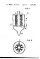
- FIGS. 6 and 7A further alternative form is shown in FIGS. 6 and 7 as filter 20b.
- the conductive pathis provided by a group of four spaced suspenders 72, the number of suspenders is a matter of choice, which are interconnected at one end by a circular ring 74 so as to form a basket like arrangement.
- One end of each suspender 72engages with conductive end cap 68 through ring 74 and the other end of each suspender engages with the conductive connector 70. In this manner the end to end conductive path is provided.
- the suspendersare held in position by being contained within a double molded clear housing having an outer wall 76 and an inner wall 78.
- FIGS. 8 and 9show another alternative form of filter 20c which once again substantially the same as the previously discussed embodiments with the exception of the form of conductive path extending between end cap 80 and the reduced tip conductive connector portion 82 at the other end.
- a centrally located porous conductive cylinder 84is provided with one end in direct contact with the conductive end cap 80 and the other end in direct contact with a centrally located disc 86 of conductive material at its other end.
- the discis supported and interconnected with a group of four angularly spaced spokes 88, the number of spokes is a matter of choice, which are in turn connected to the conductive end portion 82.
- a full conductive pathwayis provided from end to end of the filter while still maintaining the use of a clear housing 90.
- the central disc 86cooperates with the inner surface of end cap 80 to retain a filter element 92 in fixed position within the housing.
- a further embodiment of the filteris depicted as filter 20d in FIG. 10 of the drawings.
- the filteroperates the same as in the previously discussed embodiments with the exception, once again, of the conductive path between the conductive end cap 94 and the opposing end conductive connector 96.
- adhered to the outer surface of the clear housing 98is a strip 100 of conductive material.
- the stripis attached at one end to conductive connector 96 and at the other end to conductive end cap 94 thereby providing the end to end conductive path for the filter.
- the stripcan be adhered in any conventional fashion to the clear housing such as by an epoxy or it can be merely resting adjacent to or on the housing without any direct connection as long as it is connected to the end cap 94 at one end and the connector 96 at the other end.
- a final depicted form of filter 20eis depicted in FIG. 11 and is also similar in design to the previous embodiments with the exception of the design and positioning of the conductive path between one conductive end cap 102 and the other conductive end connector 104.
- a clear transparent housing 106is employed and positioned inside of the housing is a conductive strip 108 which is closely positioned to the wall of the housing or adhered thereto by a conventional epoxy or by any other similar means as in the previously discussed embodiment.
- the strip 108is connected at one end to conductive connector 104 and at the other end to conductive end cap 102 thereby providing the end to end continuous conductive path.
- the stripcan be merely positioned adjacent to the inner wall of transparent housing 106 as depicted in FIG. 11 or can be adhered directly to the surface as shown with respect to the embodiment of FIG. 10.
- the filtercould be designed with similar conductive end connections and with the clear conductive housing that would be gold filled or contain a grafted conductive surface which would provide the end to end conductive path for the filter.
Landscapes
- Chemical Kinetics & Catalysis (AREA)
- Health & Medical Sciences (AREA)
- Chemical & Material Sciences (AREA)
- Engineering & Computer Science (AREA)
- General Health & Medical Sciences (AREA)
- Life Sciences & Earth Sciences (AREA)
- Emergency Medicine (AREA)
- Biomedical Technology (AREA)
- Heart & Thoracic Surgery (AREA)
- Hematology (AREA)
- Pulmonology (AREA)
- Animal Behavior & Ethology (AREA)
- Anesthesiology (AREA)
- Public Health (AREA)
- Veterinary Medicine (AREA)
- Business, Economics & Management (AREA)
- Emergency Management (AREA)
- Environmental & Geological Engineering (AREA)
- Toxicology (AREA)
- Infusion, Injection, And Reservoir Apparatuses (AREA)
Abstract
Description
Claims (1)
Priority Applications (1)
| Application Number | Priority Date | Filing Date | Title |
|---|---|---|---|
| US05/907,900US4172709A (en) | 1976-03-23 | 1978-05-19 | Bacteria filters with transparent housings |
Applications Claiming Priority (2)
| Application Number | Priority Date | Filing Date | Title |
|---|---|---|---|
| US05/669,622US4063913A (en) | 1974-08-26 | 1976-03-23 | Bacteria filters with transparent housings |
| US05/907,900US4172709A (en) | 1976-03-23 | 1978-05-19 | Bacteria filters with transparent housings |
Related Parent Applications (1)
| Application Number | Title | Priority Date | Filing Date |
|---|---|---|---|
| US05/765,111DivisionUS4133656A (en) | 1976-03-23 | 1977-02-02 | Bacteria filters with transparent housings |
Publications (1)
| Publication Number | Publication Date |
|---|---|
| US4172709Atrue US4172709A (en) | 1979-10-30 |
Family
ID=27100150
Family Applications (1)
| Application Number | Title | Priority Date | Filing Date |
|---|---|---|---|
| US05/907,900Expired - LifetimeUS4172709A (en) | 1976-03-23 | 1978-05-19 | Bacteria filters with transparent housings |
Country Status (1)
| Country | Link |
|---|---|
| US (1) | US4172709A (en) |
Cited By (35)
| Publication number | Priority date | Publication date | Assignee | Title |
|---|---|---|---|---|
| FR2505670A1 (en)* | 1981-05-12 | 1982-11-19 | Hoerbiger Ventilwerke Ag | AIR EXHAUST FILTER FOR PNEUMATIC DEVICES |
| GB2278298A (en)* | 1993-05-29 | 1994-11-30 | Draegerwerk Ag | Filtering device |
| US5505753A (en)* | 1994-09-12 | 1996-04-09 | Heysek; Ralph G. | Aircraft pneumatic air filter |
| US5992413A (en)* | 1997-12-24 | 1999-11-30 | Enternet Medical, Inc. | Heat and moisture exchanger and generator |
| US6095135A (en)* | 1998-07-10 | 2000-08-01 | Enternet Medical, Inc. | Apparatus for providing benefits to respiratory gases |
| US6105576A (en)* | 1998-10-14 | 2000-08-22 | Enternet Medical, Inc. | Apparatus for treating respiratory gases including liquid trap |
| US6363930B1 (en) | 1998-07-10 | 2002-04-02 | Enternet Medical, Inc. | Apparatus for providing heat/moisture to respiratory gases |
| US6415788B1 (en) | 1999-07-02 | 2002-07-09 | Enternet Medical, Inc. | Apparatus for treating respiratory gases including liquid trap |
| EP1342485A1 (en)* | 2002-03-05 | 2003-09-10 | Siemens-Elema AB | Disposable filter with water trap |
| US20060157056A1 (en)* | 2005-01-18 | 2006-07-20 | Burk Marc A | Heat and moisture exchange device for respiratory therapy |
| US20090020116A1 (en)* | 2007-07-17 | 2009-01-22 | Gary James Roth | Water dissipation device with capillary action |
| US20090020124A1 (en)* | 2007-07-17 | 2009-01-22 | Gary James Roth | Permeable membrane water dissipation device |
| EP2082775A1 (en)* | 2008-01-25 | 2009-07-29 | Flodins Filter Aktiebolag | Filter |
| WO2009093977A1 (en)* | 2008-01-25 | 2009-07-30 | Flodins Filter Aktiebolag | Filter |
| US20090301479A1 (en)* | 2008-06-10 | 2009-12-10 | Covidien Ag | Filter and/or hme device for respiratory circuits comprising a condensation trap |
| US20100012127A1 (en)* | 2007-07-17 | 2010-01-21 | Teleflex Medical Incorporated | Water Dissipation Device and Method |
| US20100205798A1 (en)* | 2007-05-23 | 2010-08-19 | Brian Walker | Filter unit |
| US20100319699A1 (en)* | 2006-10-17 | 2010-12-23 | Air Safety Limited A Corporation | Filter |
| US7993071B2 (en) | 2006-10-25 | 2011-08-09 | Burrell E. Clawson | Assemblies for coupling two elements and coupled assemblies |
| US20130152929A1 (en)* | 2011-12-16 | 2013-06-20 | 12th Man Technologies, Inc. | Bacteria Filter and Heating System |
| USD760375S1 (en)* | 2011-08-05 | 2016-06-28 | Resmed Paris Sas | Filter assembly for ventilator |
| US20160243485A1 (en)* | 2015-02-20 | 2016-08-25 | Mahle International Gmbh | Air filter element and air filter |
| US20190134544A1 (en)* | 2013-04-03 | 2019-05-09 | Donaldson Company, Inc. | Liquid filter assembly and methods |
| US10709866B2 (en) | 2014-05-13 | 2020-07-14 | Fisher & Paykel Healthcare Limited | Usability features for respiratory humidification system |
| US10828482B2 (en) | 2013-12-20 | 2020-11-10 | Fisher & Paykel Healthcare Limited | Humidification system connections |
| US10974015B2 (en) | 2012-03-15 | 2021-04-13 | Fisher & Paykel Healthcare Limited | Respiratory gas humidification system |
| US11129956B2 (en) | 2012-04-27 | 2021-09-28 | Fisher & Paykel Healthcare Limited | Usability features for respiratory humidification system |
| US11173272B2 (en) | 2014-05-02 | 2021-11-16 | Fisher & Paykel Healthcare Limited | Gas humidification arrangement |
| US11278689B2 (en) | 2014-11-17 | 2022-03-22 | Fisher & Paykel Healthcare Limited | Humidification of respiratory gases |
| US11324911B2 (en) | 2014-06-03 | 2022-05-10 | Fisher & Paykel Healthcare Limited | Flow mixers for respiratory therapy systems |
| US11351332B2 (en) | 2016-12-07 | 2022-06-07 | Fisher & Paykel Healthcare Limited | Sensing arrangements for medical devices |
| US11511069B2 (en) | 2013-09-13 | 2022-11-29 | Fisher & Paykel Healthcare Limited | Humidification system |
| US11559653B2 (en) | 2014-02-07 | 2023-01-24 | Fisher & Paykel Healthcare Limited | Respiratory humidification system |
| US11801360B2 (en) | 2013-09-13 | 2023-10-31 | Fisher & Paykel Healthcare Limited | Connections for humidification system |
| US12285565B2 (en) | 2020-08-24 | 2025-04-29 | Teleflex Medical Incorporated | Self-sealing respiratory filter and condensate management apparatus |
Citations (4)
| Publication number | Priority date | Publication date | Assignee | Title |
|---|---|---|---|---|
| US3556097A (en)* | 1969-09-25 | 1971-01-19 | Air Reduction | Disposable anesthesia-breathing circuit unit |
| US3721238A (en)* | 1970-10-29 | 1973-03-20 | Ross W Inc | Disposable anesthesia device |
| US4063913A (en)* | 1974-08-26 | 1977-12-20 | Becton, Dickinson And Company | Bacteria filters with transparent housings |
| US4133656A (en)* | 1976-03-23 | 1979-01-09 | Becton, Dickinson And Company | Bacteria filters with transparent housings |
- 1978
- 1978-05-19USUS05/907,900patent/US4172709A/ennot_activeExpired - Lifetime
Patent Citations (4)
| Publication number | Priority date | Publication date | Assignee | Title |
|---|---|---|---|---|
| US3556097A (en)* | 1969-09-25 | 1971-01-19 | Air Reduction | Disposable anesthesia-breathing circuit unit |
| US3721238A (en)* | 1970-10-29 | 1973-03-20 | Ross W Inc | Disposable anesthesia device |
| US4063913A (en)* | 1974-08-26 | 1977-12-20 | Becton, Dickinson And Company | Bacteria filters with transparent housings |
| US4133656A (en)* | 1976-03-23 | 1979-01-09 | Becton, Dickinson And Company | Bacteria filters with transparent housings |
Cited By (62)
| Publication number | Priority date | Publication date | Assignee | Title |
|---|---|---|---|---|
| FR2505670A1 (en)* | 1981-05-12 | 1982-11-19 | Hoerbiger Ventilwerke Ag | AIR EXHAUST FILTER FOR PNEUMATIC DEVICES |
| GB2278298A (en)* | 1993-05-29 | 1994-11-30 | Draegerwerk Ag | Filtering device |
| US5531802A (en)* | 1993-05-29 | 1996-07-02 | Dragerwerk Aktiengesellschaft | Suction device with a filter insert in the suction line |
| GB2278298B (en)* | 1993-05-29 | 1996-12-11 | Draegerwerk Ag | Appliance including a filtering device |
| US5505753A (en)* | 1994-09-12 | 1996-04-09 | Heysek; Ralph G. | Aircraft pneumatic air filter |
| US5992413A (en)* | 1997-12-24 | 1999-11-30 | Enternet Medical, Inc. | Heat and moisture exchanger and generator |
| US6363930B1 (en) | 1998-07-10 | 2002-04-02 | Enternet Medical, Inc. | Apparatus for providing heat/moisture to respiratory gases |
| US6095135A (en)* | 1998-07-10 | 2000-08-01 | Enternet Medical, Inc. | Apparatus for providing benefits to respiratory gases |
| US6105576A (en)* | 1998-10-14 | 2000-08-22 | Enternet Medical, Inc. | Apparatus for treating respiratory gases including liquid trap |
| US6415788B1 (en) | 1999-07-02 | 2002-07-09 | Enternet Medical, Inc. | Apparatus for treating respiratory gases including liquid trap |
| EP1342485A1 (en)* | 2002-03-05 | 2003-09-10 | Siemens-Elema AB | Disposable filter with water trap |
| US20060157056A1 (en)* | 2005-01-18 | 2006-07-20 | Burk Marc A | Heat and moisture exchange device for respiratory therapy |
| US7594509B2 (en) | 2005-01-18 | 2009-09-29 | Teleflex Medical Incorporated | Heat and moisture exchange device for respiratory therapy |
| US20100319699A1 (en)* | 2006-10-17 | 2010-12-23 | Air Safety Limited A Corporation | Filter |
| US8869796B2 (en)* | 2006-10-17 | 2014-10-28 | Air Safety Limited | Filter |
| US7993071B2 (en) | 2006-10-25 | 2011-08-09 | Burrell E. Clawson | Assemblies for coupling two elements and coupled assemblies |
| US20100205798A1 (en)* | 2007-05-23 | 2010-08-19 | Brian Walker | Filter unit |
| US9009975B2 (en) | 2007-05-23 | 2015-04-21 | Walker Filtration Limited | Filter unit |
| GB2462396B (en)* | 2007-05-23 | 2012-06-20 | Walker Filtration Ltd | Filter unit |
| US20090020116A1 (en)* | 2007-07-17 | 2009-01-22 | Gary James Roth | Water dissipation device with capillary action |
| US20100012127A1 (en)* | 2007-07-17 | 2010-01-21 | Teleflex Medical Incorporated | Water Dissipation Device and Method |
| US8236081B2 (en) | 2007-07-17 | 2012-08-07 | Teleflex Medical Incorporated | Permeable membrane water dissipation device |
| US8252081B2 (en) | 2007-07-17 | 2012-08-28 | Teleflex Medical Incorporated | Water dissipation device and method |
| US20090020124A1 (en)* | 2007-07-17 | 2009-01-22 | Gary James Roth | Permeable membrane water dissipation device |
| US8105410B2 (en) | 2007-07-17 | 2012-01-31 | Teleflex Medical Incorporated | Water dissipation device with capillary action |
| EP2082775A1 (en)* | 2008-01-25 | 2009-07-29 | Flodins Filter Aktiebolag | Filter |
| WO2009093977A1 (en)* | 2008-01-25 | 2009-07-30 | Flodins Filter Aktiebolag | Filter |
| US20100313532A1 (en)* | 2008-01-25 | 2010-12-16 | Flodins Filter Aktiebolag | Filter |
| US9095675B2 (en) | 2008-01-25 | 2015-08-04 | Flodins Filter Aktiebolag | Filter |
| JP2009297513A (en)* | 2008-06-10 | 2009-12-24 | Covidien Ag | Filter and/or hme device for respiratory circuit comprising condensation trap |
| EP2133112A1 (en)* | 2008-06-10 | 2009-12-16 | Covidien AG | Filter and/or HME device for respiratory circuits comprising a condensation trap |
| US8176916B2 (en)* | 2008-06-10 | 2012-05-15 | Covidien Ag | Filter and/or HME device for respiratory circuits comprising a condensation trap |
| US20090301479A1 (en)* | 2008-06-10 | 2009-12-10 | Covidien Ag | Filter and/or hme device for respiratory circuits comprising a condensation trap |
| USD760375S1 (en)* | 2011-08-05 | 2016-06-28 | Resmed Paris Sas | Filter assembly for ventilator |
| USD827807S1 (en) | 2011-08-05 | 2018-09-04 | Resmed Paris Sas | Filter of a filter assembly for ventilator |
| USD1063060S1 (en) | 2011-08-05 | 2025-02-18 | Resmed Paris Sas | Expiratory valve for ventilator |
| USD942611S1 (en) | 2011-08-05 | 2022-02-01 | Resmed Paris Sas | Expiratory adaptor for a ventilator |
| US9010321B2 (en)* | 2011-12-16 | 2015-04-21 | 12th Man Technologies, Inc. | Bacteria filter and heating system |
| US20130152929A1 (en)* | 2011-12-16 | 2013-06-20 | 12th Man Technologies, Inc. | Bacteria Filter and Heating System |
| US10974015B2 (en) | 2012-03-15 | 2021-04-13 | Fisher & Paykel Healthcare Limited | Respiratory gas humidification system |
| US12350436B2 (en) | 2012-03-15 | 2025-07-08 | Fisher & Paykel Healthcare Limited | Respiratory gas humidification system |
| US11129956B2 (en) | 2012-04-27 | 2021-09-28 | Fisher & Paykel Healthcare Limited | Usability features for respiratory humidification system |
| US11878093B2 (en) | 2012-04-27 | 2024-01-23 | Fisher & Paykel Healthcare Limited | Usability features for respiratory humidification system |
| US10717028B2 (en)* | 2013-04-03 | 2020-07-21 | Donaldson Company, Inc. | Liquid filter assembly and methods |
| US20190134544A1 (en)* | 2013-04-03 | 2019-05-09 | Donaldson Company, Inc. | Liquid filter assembly and methods |
| US11511069B2 (en) | 2013-09-13 | 2022-11-29 | Fisher & Paykel Healthcare Limited | Humidification system |
| US11801360B2 (en) | 2013-09-13 | 2023-10-31 | Fisher & Paykel Healthcare Limited | Connections for humidification system |
| US12053589B2 (en) | 2013-09-13 | 2024-08-06 | Fisher & Paykel Healthcare Limited | Humidification system |
| US11826538B2 (en) | 2013-12-20 | 2023-11-28 | Fisher & Paykel Healthcare Limited | Humidification system connections |
| US10828482B2 (en) | 2013-12-20 | 2020-11-10 | Fisher & Paykel Healthcare Limited | Humidification system connections |
| US11559653B2 (en) | 2014-02-07 | 2023-01-24 | Fisher & Paykel Healthcare Limited | Respiratory humidification system |
| US12397127B2 (en) | 2014-02-07 | 2025-08-26 | Fisher & Paykel Healthcare Limited | Respiratory humidification system |
| US11173272B2 (en) | 2014-05-02 | 2021-11-16 | Fisher & Paykel Healthcare Limited | Gas humidification arrangement |
| US11992622B2 (en) | 2014-05-13 | 2024-05-28 | Fisher & Paykel Healthcare Limited | Usability features for respiratory humidification system |
| US10709866B2 (en) | 2014-05-13 | 2020-07-14 | Fisher & Paykel Healthcare Limited | Usability features for respiratory humidification system |
| US11712536B2 (en) | 2014-06-03 | 2023-08-01 | Fisher & Paykel Healthcare Limited | Flow mixers for respiratory therapy systems |
| US11324911B2 (en) | 2014-06-03 | 2022-05-10 | Fisher & Paykel Healthcare Limited | Flow mixers for respiratory therapy systems |
| US11278689B2 (en) | 2014-11-17 | 2022-03-22 | Fisher & Paykel Healthcare Limited | Humidification of respiratory gases |
| US10150074B2 (en)* | 2015-02-20 | 2018-12-11 | Mahle International Gmbh | Air filter element and air filter |
| US20160243485A1 (en)* | 2015-02-20 | 2016-08-25 | Mahle International Gmbh | Air filter element and air filter |
| US11351332B2 (en) | 2016-12-07 | 2022-06-07 | Fisher & Paykel Healthcare Limited | Sensing arrangements for medical devices |
| US12285565B2 (en) | 2020-08-24 | 2025-04-29 | Teleflex Medical Incorporated | Self-sealing respiratory filter and condensate management apparatus |
Similar Documents
| Publication | Publication Date | Title |
|---|---|---|
| US4172709A (en) | Bacteria filters with transparent housings | |
| US4063913A (en) | Bacteria filters with transparent housings | |
| US4133656A (en) | Bacteria filters with transparent housings | |
| US4171962A (en) | Bacteria filters with transparent housings | |
| US4181512A (en) | Bacteria filters with transparent housings | |
| CA1054073A (en) | Gas purging fluid filter | |
| US5213096A (en) | Apparatus for connecting a patient to breathing devices, the apparatus including a bacteria filter and gas sampling means | |
| US4558708A (en) | Patient's airway adapter to withdraw a patient's gas samples for testing free of sputum mucus and/or condensed water, by utilizing a hollow cylindrical hydrophobic liquid baffle | |
| US5482031A (en) | Arrangement for connecting a patient to a respirator, and the use of a moisture-heat-exchanger in the arrangement | |
| US5367604A (en) | Humidifier apparatus and/or gases distribution chambers and/or temperature probe | |
| US4679573A (en) | Adaptor assembly for airway tube | |
| US4253468A (en) | Nebulizer attachment | |
| US4985055A (en) | Liquid/gas separation device | |
| US3892533A (en) | Oxygenator gas distribution header | |
| US3903884A (en) | Manifold nebulizer system | |
| US4108172A (en) | Carbon dioxide absorption canister for use with analgesia equipment | |
| US3912795A (en) | Humidifying gas | |
| EP0009543B1 (en) | Nested hollow fiber humidifier | |
| US4512771A (en) | Venting assembly for a sealed body fluid drainage device | |
| SE503771C2 (en) | Device for moisture-heat exchanger | |
| US4181511A (en) | Bacteria filters with transparent housings | |
| US5616158A (en) | Moisture absorbing media filter | |
| GB2000685A (en) | Vented filter assembly | |
| US4111807A (en) | Mouth filter for use with pipettes | |
| US3077268A (en) | Dialyzer |
Legal Events
| Date | Code | Title | Description |
|---|---|---|---|
| AS | Assignment | Owner name:DART INDUSTRIES, INC., 2211 SANDERS ROAD, NORTHBRO Free format text:ASSIGNMENT OF ASSIGNORS INTEREST.;ASSIGNOR:BECTON, DICKINSON AND COMPANY;REEL/FRAME:004257/0066 Effective date:19840229 | |
| AS | Assignment | Owner name:PROFESSIONAL MEDICAL PRODUCTS, INC., 525 NORTH EME Free format text:ASSIGNMENT OF ASSIGNORS INTEREST.;ASSIGNOR:DART INDUSTRIES INC., A DE CORP;REEL/FRAME:004659/0818 Effective date:19861027 Owner name:PROFESSIONAL MEDICAL PRODUCTS, INC., A DE CORP,SOU Free format text:ASSIGNMENT OF ASSIGNORS INTEREST;ASSIGNOR:DART INDUSTRIES INC., A DE CORP;REEL/FRAME:004659/0818 Effective date:19861027 | |
| AS | Assignment | Owner name:GENERAL ELECTRIC CREDIT CORPORATION, A CORP. OF N. Free format text:ASSIGNMENT OF ASSIGNORS INTEREST.;ASSIGNOR:PROFESSIONAL MEDICAL PRODUCTS, INC.;REEL/FRAME:004665/0944 Effective date:19860915 | |
| AS | Assignment | Owner name:PROFESSIONAL MEDICAL PRODUCTS, INC., SOUTH CAROLIN Free format text:RELEASED BY SECURED PARTY;ASSIGNOR:GENERAL ELECTRIC CAPITAL CORPORATION, F/K/A GENERAL ELECTRIC CREDIT CORPORATION;REEL/FRAME:005300/0821 Effective date:19900328 | |
| AS | Assignment | Owner name:TYCO INTERNATIONAL (US) INC., NEW HAMPSHIRE Free format text:CHANGE OF NAME;ASSIGNOR:TYCO INTERNATIONAL LTD.;REEL/FRAME:008604/0376 Effective date:19970702 Owner name:TYCO INTERNATIONAL LTD., NEW HAMPSHIRE Free format text:MERGER;ASSIGNOR:KENDALL COMPANY, THE;REEL/FRAME:008604/0384 Effective date:19961231 Owner name:KENDALL COMPANY, THE, MASSACHUSETTS Free format text:MERGER;ASSIGNOR:PROFESSIONAL MEDICAL PRODUCTS, INC.;REEL/FRAME:008604/0366 Effective date:19960531 |