US4171572A - Light control apparatus for a dental handpiece - Google Patents
Light control apparatus for a dental handpieceDownload PDFInfo
- Publication number
- US4171572A US4171572AUS05/863,289US86328977AUS4171572AUS 4171572 AUS4171572 AUS 4171572AUS 86328977 AUS86328977 AUS 86328977AUS 4171572 AUS4171572 AUS 4171572A
- Authority
- US
- United States
- Prior art keywords
- fluid
- amplifier
- handpiece
- light source
- line
- Prior art date
- Legal status (The legal status is an assumption and is not a legal conclusion. Google has not performed a legal analysis and makes no representation as to the accuracy of the status listed.)
- Expired - Lifetime
Links
Images


Classifications
- A—HUMAN NECESSITIES
- A61—MEDICAL OR VETERINARY SCIENCE; HYGIENE
- A61C—DENTISTRY; APPARATUS OR METHODS FOR ORAL OR DENTAL HYGIENE
- A61C1/00—Dental machines for boring or cutting ; General features of dental machines or apparatus, e.g. hand-piece design
- A61C1/08—Machine parts specially adapted for dentistry
- A61C1/088—Illuminating devices or attachments
- Y—GENERAL TAGGING OF NEW TECHNOLOGICAL DEVELOPMENTS; GENERAL TAGGING OF CROSS-SECTIONAL TECHNOLOGIES SPANNING OVER SEVERAL SECTIONS OF THE IPC; TECHNICAL SUBJECTS COVERED BY FORMER USPC CROSS-REFERENCE ART COLLECTIONS [XRACs] AND DIGESTS
- Y10—TECHNICAL SUBJECTS COVERED BY FORMER USPC
- Y10T—TECHNICAL SUBJECTS COVERED BY FORMER US CLASSIFICATION
- Y10T137/00—Fluid handling
- Y10T137/3584—Inflatable article [e.g., tire filling chuck and/or stem]
- Y10T137/36—With pressure-responsive pressure-control means
- Y10T137/3631—Diaphragm, bellows or expansible tube
Definitions
- This inventionrelates to an improved apparatus for controlling the operation of an oral illumination system associated with a fluid driven or an electrically driven dental handpiece unit.
- some dental handpiece unitshave associated therewith one or more fiber optic bundles which direct a beam of light to the region of a patient's tooth which is being drilled. See, for example, U.S. Pat. Nos. 2,539,828 to Goldis et al; 3,397,457 to Gosselin; 3,634,938 to Hutchinson; 3,638,013 to Keller; 3,683,503 to Klein; and 3,897,134 to Scrivo.
- the apparatus of this inventionsolves the problem of momentary dazzle by providing means to illuminate the oral cavity just prior to the dentist inserting the drill of the handpiece into the patient's mouth.
- the apparatus of this inventionalso allows the light to remain lit for a predetermined period of time after drilling has ceased thereby enabling the dentist, if desired, to examine the drilled area with the aid of the light emitted at the operative end of the handpiece.
- the predetermined period of timecan be varied as desired, and after the light is automatically extinguished the dentist may examine or change the burr, etc.
- the apparatus of this inventionalso allows the dentist to illuminate a patient's mouth using the light associated with the handpiece prior to drilling by providing means to turn on the light and maintain it on for a predetermined period of time.
- This inventionis an apparatus for controlling the actuation of a light source for illuminating the work zone adjacent the operative end of a dental handpiece.
- the dental handpiecehas an operative end; means to transmit power to the operative end; control means associated with the power transmitting means so that when the control means is actuated, power is transmitted to the operative end; and a light source for illuminating the region adjacent the operative end of the handpiece.
- the apparatus of the inventioncontrols the actuation of the light-source and comprises (a) means for actuating the light-source when a signal is transmitted thereto; (b) means for transmitting a signal from the power transmitting means to the actuating means; and (c) delay shutoff means associated with the actuating means to maintain the light source on for a predetermined period of time after transmission of power to the operative end of the handpiece is terminated, and then causing the light source to be extinguished at the end of said predetermined period of time.
- the control apparatus of this inventionmay be employed with an electrically or fluid driven dental handpiece, preferably the latter and especially the pneumatically driven type.
- the delay meansmay also be electrically or pneumatically operated. It is preferred that the control apparatus of this invention is employed with a light source and light transmitting means integral with the dental handpiece.
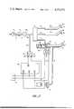
- FIG. 1is a schematic diagram of a control apparatus for a pneumatically driven handpiece wherein a pneumatic switch regulates the actuation of a remote light for a fiber optic means and an air pressure accumulator provides a delay means to maintain the light on after the air supply is turned off.
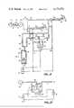
- FIG. 2is a schematic diagram of a control apparatus for a pneumatically driven handpiece wherein a pneumtic switch regulates the actuation of a remote light for a fiber optic means and the delay means is an electrical circuit. An additional arming switch for the light is associated with the handpiece.
- FIG. 3is a cross-sectional view of a pneumatic delay means and switch particularly suitable for use in the invention shown in FIG. 1.
- FIG. 4is a schematic diagram of a control apparatus for an electrically driven dental handpiece wherein an electrically-actuated switch regulates the actuation of a remote light for a fiber optic means, and the delay means is an electrical circuit.
- FIG. 5is a circuit diagram of an electrical delay means for the light source.
- FIG. 6is a schematic diagram of a pneumtic control apparatus for a plurality of dental handpieces wherein a single switch and associated pneumatic delay means controls actuation of a plurality of lights, a separate light being integral with each of the handpieces being controlled.
- FIG. 7is a schematic diagram of a lighting system for FIG. 6 except that only one handpiece light is actuated at one time.
- FIG. 8is a schematic diagram of a pneumatic control apparatus for a plurality of dental handpieces wherein a pneumatic delay means and switch are associated with each handpiece, each handpiece having a light source adjacent the non-working end thereof and fiber optic means for transmitting the light emitted by the light source to the working end of the handpiece. In addition an independent fiber optic probe is shown.
- FIG. 9is a schematic diagram of a pneumatic control apparatus for two handpieces having a single pneumatic delay means and switch for a light in each of two handpieces, and means to energize the light in either handpiece, as desired.
- FIG. 10is a schematic diagram of a thermally actuated delay means and switch to control the actuation of a light-producing means.
- FIG. 11is a perspective view of the assembled apparatus schematically described in FIG. 8.
- This inventionrelates to an apparatus for controlling the actuation of a light source to illuminate the region adjacent the operative end of a dental handpiece.
- the dental handpiecefor purposes of this application can be any appropriate powered dental tool having at least one operative end.
- suitable dental handpiecesinclude a tissue cutter, a scaler, a low-speed drill or a high speed drill.
- the "operative end" of the handpieceis that end which is away from the end which is held and which is used by the dentist to perform the desired operation, e.g. cutting, scaling or drilling.
- a drill handpieceincludes a drill head at the operative end thereof and means within the drillhead for receiving, securely holding and rotating a drill or burr inserted therein.
- the drill receiving meanswill be a collet and shaft assembly mounted for low- or high-speed rotation as is known in this field.
- Meansare also provided to rotate the drill receiving means, such as a turbine, including means for transmitting power to the drill rotating means and a control means associated with the power-transmitting means so that when the control means is actuated, power is transmitted to the drill rotating means.
- An exemplary scaler handpieceincludes a scraper at the operative end of the handpiece along with means to vibrate the scraper at an appropriate rate.
- a scaleris more fully disclosed in U.S. Pat. No. 3,811,190 to Sertich.
- the dental handpiecewhether scaler, cutter or drill, also has associated therewith a light source for illuminating the region adjacent the operative end of the dental handpiece.
- the control apparatus of the inventioncomprises
- the control apparatus of this inventioncan be integrated into a dental delivery system or can be an "add on" unit for use in conjunction with an existing dental delivery system.
- the control unitmay be employed in both fluid-driven dental handpiece units as well as electrically-driven units, preferably the former.
- the "signal" which is transmitted to the actuating means of (b), abovemay be electrical or fluid, e.g. pneumatic.
- the actuating means of (a), aboveis shown in the Figures as a switch, that is, a device which completes or breaks the path of a current to the light source.
- the dental handpieceis depicted as a drill handpiece. It is to be understood, however, that any appropriate powered dental handpiece discussed hereinbefore can be used, with appropriate modifications as would be apparent in view of this disclosure.
- FIG. 1schematically sets forth a specific embodiment of the apparatus of this invention which is a fluid-driven unit, specifically air-driven (pneumatic).
- a fluid-driven unitspecifically air-driven (pneumatic).
- suitable fluidssuch as nitrogen could also be employed.
- Dental delivery system 1has associated therewith a source 2 for supplying pressurized air at about 100 pounds per square inch (psi) pressure.
- Source 2can be any means known in the art for this purpose, such as a suitable air pump or compressor. These are commonly used in the dental profession and are well known per se. Such compressors are generally part of the equipment available in a dental or medical building.
- airprovides the power or motive force for the handpiece.
- the power transmitting meansare air lines 4, 4a and 4b which transmit air to handpieces 6, 6a and 6b, respectively.
- pressure regulator 3a device readily available from companies such as Watts Regulator Co., 10 Embankment St. Lawrence, Mass. 01841; Humphrey Inc., 9212 Balboa Avenue, San Diego, Calif. 92123; or Clippard Instrument Laboratory, Inc., 7382 Colerain Road, Cincinnati, Ohio 45239.
- Air line 4may pass directly to the handpiece or, as shown in FIG. 1, may first pass through a manifold 5 where a selection can be made between the plurality of handpieces, at least one handpiece 6 being associated with a light source, shown here as a remote light 10, and a fiber-optic transmitting means 8.
- the other handpieces 6a or 6bare shown as having no light or fiber-optic transmitting means associated therewith. If handpiece 6a or 6b is chosen, the air passes through lines 4a or 4b, respectively.
- the manifold 5may be designed so that the dentist manually selects via a switch (not shown) the handpiece to which air will flow, or the air can automatically flow to the handpiece selected after it is lifted from a hanger (not shown), as generally shown by Austin U.S. Pat. No. 28,649 or Morgan U.S. Pat. No. 3,918,161.
- All handpieceshave a pneumatically driven turbine within drillhead or housing 9, 9a or 9b to operate the respective drills 7, 7a or 7b and are of a design well known in the art. See for example U.S. Pat. Nos. 3,074,167; 3,120,706, 3,499,223; 3,893,242; 3,946,490; 3,947,966; etc.
- control meanssuch as foot control (not shown) which, when actuated, allows power to be transmitted to the appropriate drill. See U.S. Pat. No. 3,596,102.
- valve means 26opens to allow air to flow through lines 4, 4a or 4b and manifold 5 to handpieces 6, 6a or 6b, respectively.
- Valve means 26is located between pressure regulator 3 and handpiece 6 and preferably is between manifold 5 and regulator 3 as shown in FIG. 1.
- the valvemay be opened or closed by actuating a foot or finger switch, which may be located on the handpiece in the latter case, the valve is preferably incorporated into a pedal operated by the dentist with his foot so that the valve opens when the dentist steps on the foot pedal.
- a light sourceconsisting of (i) fiber optic means 8, which may be for example a plastic light pipe, a fiber bundle or the like, positioned to transmit light to the region to be drilled and (ii) a light-producing means such as light 10, positioned adjacent the remote end of fiber optic means 8, along with means to energize the light-producing means, such as a source of power 12 for the light 10 and means, e.g. electrical line 11, to transmit power to the light.
- Light 10 of appropriate small dimensioncan be integral with handpiece 6 (see, e.g. Hutchinson U.S. Pat. No. 3,634,938) or can be spaced from the handpiece as shown in FIG. 1 (see, e.g.
- U.S. Pat. No. 3,638,013 to KellerIn the latter case, the light is generally relatively large and will require a cooling fan 13 as shown in FIG. 1. In addition, it is generally advantageous to include rheostat 14 in electrical line 11 to control the intensity of light 10.
- a suitable fiber optic unit for incorporation with this inventionis Model No. UL 30G made by Vicon Inc., Pelham Manor, N.Y.
- a light of appropriately small dimensionmay be integral with the handpiece and located at the operative end thereof. In this case, no fiber optic means is needed. See, for example, U.S. Pat. No. 2,038,911 to Stutz et al; French Pat. No. 1,123,034 to Pestel; and German Pat. No. 853,494.
- pneumtically actuated switch 16 associated with electrical line 11controls actuation of the light-producing means by controlling the flow of electricity to light 10 from power source 12.
- switch 16When switch 16 is closed, power flows from source 12 to actuate cooling fan 13 and lamp 10 which then illuminates one end of fiber optic means 8 thus causing light to be transmitted to the region near drill 7 of handpiece 6 to illuminate the desired area.
- switch 16When switch 16 is open, lamp 10 is off and no light is transmitted along fiber optic means 8.
- Air transmittal line 20transmits a signal, in this case air, from line 4 to switch 16. Air transmittal line 20 joins with line 4 at junction 21 prior to entering handpiece 6 but after exiting from manifold 5 in a simple "T" or "Y" connection as is well known in the art. Alternatively, air transmittal line 20 can be connected directly to the manifold itself. Line 20 may be of any material generally used such as metal or plastic, preferably polyurethane.
- Switch 16closes when air passes through air line 4 and air transmittal line 20 to the right-hand side of pneumatic switch 16.
- Delay means 15is associated with switch 16 to hold the switch closed for a predetermined period of time, and thus maintain light 10 on for that period of time, after the transmission of pressure, in this case air, to the handpiece 6 has ceased.
- one-way valve 22allows air to be transmitted first to air storage unit 24 and then to pneumatically actuated switch 16, but does not allow air to flow in the opposite direction. The air pressure causes switch 16 to close and activate light 10. Since an excess amount of air is stored in storage unit 24, once the passage of air through valve 22 is terminated, switch 16 will remain closed and the light 10 will remain on for a predetermined period of time depending on the capacity of storage unit 24 and the rate of release through bleeder orifice 25.
- the stored airwill escape to the atmosphere through bleeder orifice 25 thus eventually relieving the pressure on pneumatic switch 16 and allowing it to open whereupon lamp 10 will be extinguished.
- the storage unit, one-way valve and bleeder orificeact as a delay means for maintaining the light source in an energized condition after the transmission of air to handpiece 6 has been stopped.
- a suitable resistorcan connect points 17a and 17b to keep a maintenance voltage across the light when switch 16 opens. This expedient decreases the "thermal shock" to the light source and extends the life of the light. However, even with the presence of the resistor, light 10 will be essentially “extinguished” when switch 16 is opened.
- FIG. 3A particularly suitable pneumatic delay means and switch are shown in FIG. 3, wherein like numerals as used in FIG. 1 refer to like elements.
- the air storage unit 24, bleeder orifice 25, one way valve 22, and pressure switch 16are all housed in a single cylindrical unit 19.
- the airenters through air transmission line 20, inlet 23 and one-way valve 22, which is inside air storage unit 24 instead of outside as in FIG. 1.
- the one-way valveis a "duckbill" valve commonly used in the art.
- membrane 18When sufficient air enters the storage unit 24, it causes membrane 18 to deflect which causes contact closure at 17 to allow current to flow through line 11 to energize light 10.
- the "duckbill" valve 22prevents air in storage unit 24 from escaping through inlet 23 so air escapes through bleeder valve 25 until the pressure on membrane 18 is low enough, i.e. about atmospheric, to break contact at switch 16 and thus stop current flow through line 11.
- the length of the delayis easily modified by inserting a bleeder orifice having a different orifice size as desired. Generally a time of about 10-15 seconds is considered satisfactory.
- the dentistselects which handpiece he desires to use, e.g. handpiece 6, picks it up from its hanger, and presses the foot pedal, not shown, to open valve 26 and allow air to flow through line 4 to handpiece 6 and pneumatic switch 16, to turn on lamp 10, and actuate drill 7.
- the dentistproceeds with his work, occasionally stopping the drill to view the drilled region with the light transmitted by fiber-optic means 8 from light 10 which stays energized for a predetermined period of time due to air stored in storage unit 24 even though control valve 26 is closed and drill is not operating.
- the dentistis finished, he removes his foot from the foot pedal thus stopping air flow to handpiece 6 and switch 16.
- the systemmay be designed to incorporate an override means (not shown) which, when actuated, allows orifice 25 to open and immediately release sufficient air from storage unit 24, thereby causing switch 16 to open and shut off light 10 essentially simultaneously with the stoppage of drive air flow to the handpiece being used by the dentist.
- override meanscan, for example, be incorporated into the handpiece cradle in which case the light will be extinguished (if not already extinguished) when the handpiece is replaced on the cradle.
- the handpiece handlecan contain a limit switch which will open the circuit to the lamp.
- FIG. 2a schematic diagram of another embodiment of this invention is shown, wherein like numerals as used in FIG. 1 refer to like elements.
- the unitis pneumatically driven by air supplied from source 2 through pressure regulator 3, line 4, and valve 26 to manifold 5 which has an internal logic system which directs the drive air to the proper handpiece after the dentist has removed handpiece 6 from its associated hanger.
- one handpieceis associated with fiber-optic means 8 which transmits light from light 10, energized by electricity from source 12.
- air line 20joins transmittal line 4 at juncture 21a before reaching manifold 5 and communicates with pneumatically actuated switch 16 which is closed by the superatmospheric air pressure when valve 26 is opened.
- Arming switch 32is in the open condition when handpiece 6 is in hanger 30.
- Delay means 34is connected to switch 16 as shown.
- delay means 34is an electrically actuated delay, preferably of a solid state design. Particularly useful in this regard is a totally solid state timer from SSAC, Inc., P.O. Box 395, Liverpool, N.Y. referred to as the VERSA-TIMER.
- This delay meansmay be of fixed time delay mode or may have an external adjustment, e.g. a variable resistor, to modify the predetermined time period chosen as the delay time. In FIG. 2 the delay is shown as a fixed time delay mode.
- hanger switch 32 and line 31 associated with hanger 30can be eliminated, in which case, once the dentist releases the foot control, the pressure collapses but delay circuit 34 holds the lamp on for a predetermined period of time even if the handpiece is returned to hanger 30. The lamp automatically goes out once the period of time is completed.
- line 20would have to connect to air line 4 between manifold 5 and handpiece 6, as discussed hereinbefore regarding FIG. 1, to prevent the light from coming on when handpiece 6a or 6b was lifted from its respective hanger.
- switch 16operates in the apparatus set forth in FIGS. 1 and 2 to actuate light 10, the mode of operation to maintain the light on differs in each case.
- FIG. 1light 10 stays on only as long as switch 16 is closed, but when switch 16 opens, light 10 is extinguished.
- FIG. 2on the other hand, light 10 remains on even if switch 16 opens, because the delay means associated with switch 16 maintains the light 10 on for the desired time.
- valve 26is actuated by a control means, preferably a foot pedal, which the dentist operates as desired to allow air to flow to handpiece 6 and operate drill 7.
- the foot pedalmay be electrical, pneumatic or mechanical. If electrical, valve 26 is a solenoid valve and depressing the foot pedal causes current to flow to the solenoid and open valve 26. If, on the other hand, the foot pedal is pneumatic, valve 26 is a pneumatic valve and depressing the pedal causes air to flow to pneumatic valve 26 and open it. Alternatively, valve 26 may be mechanical and integral with the foot pedal so that when the foot pedal is depressed valve 26 opens and air flows through line 4 to handpiece 6.
- FIG. 4sets forth a dental delivery system having electrically driven handpieces and an electronic delay 134.
- Normal customer electrical poweris supplied to transformer 103, which reduces the voltage to a safe level and isolates the remainder of the circuit.
- Handpieces 106, 106a, 106bare driven by electric motors 201, 201a, 201b respectively.
- Switching manifold 105is similar in logic performance to pneumatic manifold 5 and allows the dentist to select which handpiece he desires to use by closing appropriate switch 111, 111a or 111b.
- the dentistselects which handpiece he will use and lifts, e.g., handpiece 106 from its hanger, not shown.
- Switch 111is closed either manually or automatically to ready the line 104 to receive current.
- the dentistwishes to start drilling he closes switch 126, preferably by pressing a foot pedal (not shown) and electricity then flows to electric motor 201 in handpiece 106 to actuate drill 107 in housing 109.
- electricityis transmitted to electrical relay switch 116 via line 120 which closes to complete the circuit which actuates light 110.
- Lightis transmitted along fiber-optic means 108 to the operative end of handpiece 106 to illuminate the region being drilled.
- handpiece 106can be associated with an arming switch such as shown in FIG. 2 and discussed hereinbefore.
- FIG. 5one can see a detailed schematic circuit diagram of a representative electric delay means 234 of solid state design having a fixed time mode suitable for use in the apparatus of this invention.
- a delay meansis readily employed, in the apparatus shown in FIGS. 2, 4 and 8 and may be readily modified as desired by one skilled in this art.
- Transformer 212supplies power not only to energize the light 218 but also to operate the delay circuit for delay means 234.
- currentis constantly supplied from transformer 212 to a full wave bridge rectifier 236 in the delay circuit to convert the AC output of the transformer to DC current and operate the delay circuit.
- switch 204When the voltage coming from operational amplifier 222 at point 220 is sufficiently large, for example, 3.3 volts direct current, switch 204 will close and light 218 will be on, but when the voltage at point 220 drops below a certain set value, for example, 0.3 volts direct current, switch 204 will open thus extinguishing light 218.
- operational amplifier 222for example, Item No. LM 358 from Texas Inst.
- Dallas, Tx.operates in essentially two states to provide the necessary voltage to operate switch 204.
- the output of the amplifierthat is the voltage at point 220 is approximately 0.3 volts direct current.
- the switch 204will be open.
- the output of amplifier 222is then about 3.3 volts DC, which is sufficient to close the switch 204 and allow light 218 to go on.
- rectifier 236is needed if the input current to transformer 212 is Ac current. If, on the other hand, direct current is available, transformer 212 and rectifier 236 are not needed.
- pressure switch 216(corresponding to switch 16 in FIGS. 2, 4 or 8) is closed, that is the dentist has pressed the foot pedal to allow air pressure to flow to pressure switch 216 and close the switch, the voltage at 226 will become the same as the voltage at 228 or approximately 6 volts direct current. Since at that point the voltage at 224 will be less than the voltage at 226, the voltage at 220 will become 3.3 volts DC, thus providing sufficient current through coil 205 to close Reed switch 204 and energize light 218.
- switch 216opens due to a lack of air pressure, the voltage at 226 will not drop to 0 immediately because of a charge stored in capacitor 230. The voltage at 226 will slowly decrease through resistor-capacitor-ground combination 230, 232, 233.
- the output of amplifier 222will be 0.3 volts DC, thus allowing switch 204 to swing open and extinguish light 218.
- the time required for the voltage at 226 to decrease to below the voltage at 224 after switch 216 opensdetermines the time delay period of the circuit. Preferably this time is about 10-15 seconds.
- a filter capacitor 237is employed to smooth out ripple output of the bridge rectifier and a diode 238 is used to prevent current from feeding back into the operational amplifier 222.
- Resistors 240, 242 and ground 244are chosen to give a voltage of 0.3 volts at point 224.
- the line 215 extending from contact 214provides access to set up a series of delay means modules each of which can be used with an individual handpiece and light source for illuminating the region adjacent the operative end of the handpiece.
- the lightmay be located in the handpiece as shown in schematic FIG. 6 or 8 (e.g. in a handpiece module which readily fits into the handpiece), or in the handpiece adjacent the operative end when fiber optics are not utilized as shown in FIG. 9.
- the delay meansprevents the light from staying on for a long period of time when no air is flowing, thus preventing the handpiece from overheating due to heat generated by the light source.
- the apparatuscan be designed to be used with a plurality of dental handpieces, each having a light producing means and fiber optic means integral with the handpiece.
- like numeralsrefer to like elements as found in FIGS. 1 and 2.
- valve 26which is operated by a suitable means, preferably on a foot pedal, not shown.
- valve 26opens and allows air to flow to manifold 5 which is designed to allow the air to flow through lines 4, 4a or 4b when the corresponding handpiece 6, 6a or 6b is picked up.
- manifold 5adjusts to allow air to flow to line 4 and handpiece 6.
- Switch 40is designed to close when handpiece 6 is picked up, thus allowing current to flow to lamp 10 if switch 16 is closed. As air is flowing through line 4, it also flows through "T" connection 21a and line 20 to pneumatic delay means 15 via one-way valve 22 thereby causing switch 16 to close, thus, allowing current to flow from the power source 12 to energize light 10.
- the illumination produced by light 10is transmitted along fiber optic means 8 to the region near drill 7 so that the dentist can see the area which is being drilled.
- valve 26When valve 26 is closed, the flow of air to delay means 15 and handpiece 6 ceases, but the air contained in storage unit 24 keeps switch 16 closed for a predetermined period of time while the air bleeds through orifice 25. Thus, the dentist can view the area that has just been drilled with the aid of light eminating from fiber optic means 8.
- switch 40opens thereby automatically extinguishing light 10 if the predetermined period of time has not yet expired.
- Rheostat 14can be used to adjust the intensity of light emitted by lights 10, 10a or 10b.
- FIG. 8a particularly preferred arrangement for a plurality of handpieces, each having its own light producing means is shown schematically in FIG. 8, where like numerals refer to like elements as in FIG. 6 and like elements concerning the electric delay means of FIG. 5.
- individual delay means 34, 34aare associated with each individual handpiece 6, 6a, respectively.
- FIG. 8only two handpieces are shown as being associated with manifold 5; however, it is to be understood that any number of handpieces can be associated with manifold 5 as required by the individual dentist.
- Valve 26is opened by pressing foot pedal, not shown, to allow air to flow to the manifold.
- the logic system of manifold 5directs the air from the manifold to the lifted handpiece.
- the airflows through line 4, it also flows through line 20 to pressure switch 16, which closes, to energize light 10 through delay means circuit 34 as described in the discussion of FIG. 5.
- Light producedis transmitted via light transmitting means 8 to the region of drill 7 so that the dentist can see the area which is being drilled in the patient's mouth.
- valve 26closes and the air flow stops and switch 16 opens, but light 10 remains on for the predetermined period of time due to the action of delay means 34 in keeping current flowing to light 10.
- the dentistcan also use handpiece 6a which operates similarly.
- the apparatuscan optionally include a separate circuit for a remote lighting means such as exploratory probe 78 which is operated independently of handpieces 6 and 6a.
- a remote lighting meanssuch as exploratory probe 78 which is operated independently of handpieces 6 and 6a.
- closing switch 70allows current to flow from power source 12 to energize light 74.
- the illumination from light 74is transmitted along fiber optic means 76 to probe end 79 which the dentist employs, independently of the use of the handpieces, to examine a patient's mouth.
- Another embodimentwould illuminate via light 74 positioned at the end of probe 78 and would not require a fiber optic means.
- Rheostat 80is used to adjust the intensity of light 74.
- FIG. 9Still another embodiment of the apparatus of this invention is schematically shown in FIG. 9.
- valve 26is opened to allow air flow through manifold 5, lines 4a, 46, 48, through one-way valves 47 and 22 to air storage means 24 to cause diaphragm 18 to expand and close switch 16.
- line 48which is in fluid communication with line 4a
- accordian element 49expands until it forces toggle switch 50 to contact point 51a, thus completing the circuit and allowing lamp 10a to light.
- Switch 50 and contacts 51a, 51bcomprise a bistable single pole, double throw switch with no center off position.
- Bellows 49only pushes switch 50 to contact 51a while bellows 43 only pushes switch 50 to contact 51b and the only time switch 50 moves from one position to another is when the dentist changes handpieces.
- Air storage unit 24retains switch 16 in a closed position and allows the light 10 to remain on for a predetermined period of time until the air in the storage unit bleeds out through orifice 25.
- valve 26If the dentist wishes to use handpiece 6 after he replaces handpiece 6a, he picks up handpiece 6 and opens valve 26 to allow air to flow through manifold 5, lines 4, 40, 42 through one-way valves 41, 22 to air storage 24 and diaphragm 18 thus closing switch 16. Air expands accordian element 43 to push switch 50 into contact 51b thus completing the circuit and causing light 10 to light. When the dentist closes valve 26, air flow ceases but switch 50 remains contacting point 51b and light 10 remains on for a predetermined period of time as discussed before.
- FIG. 10sets forth an alternative delay means which can be used in the apparatus of this invention, especially if the light is within the handpiece.
- airflows to lines 4 and 4d to cause diaphragm 62b to expand and reset thermal switch 62.
- Current from source 12flows to light 10, simulator resistor 60, and resettable thermal switch 62.
- Light 10will remain on as long as switch 62 is closed to complete the circuit.
- the air passing simulator resistor 60draws heat away from the resistor thus keeping the temperature down, maintaining the thermal switch 62 closed to maintain the light on.
- thermocouplecan be employed in place of the thermal switch. Heat from light 10 causes the thermocouple to open at its predetermined or built-in limit, and thus stop current flow.
- the air flow patterncan be designed to cool the handpiece enclosure and thermocouple so that, as long as air flows, the temperature of the thermocouple remains sufficiently low and the light remains on. However, when air flow stops, the temperature rises to a point where the thermocouple opens, thus stopping current flow and turning off the light.
- FIG. 11we see a perspective view of the apparatus of this invention which corresponds to the schematic diagram set forth in FIG. 8.
- Box 140contains a transformer and protection circuits for the apparatus of the invention.
- Electrical line 142leads from box 140 to box 144 which contains the switch for the light-producing means and the delay means associated with that switch.
- air transmittal line 146is also associated with the switch and delay means connected to means 148 for transmitting a signal from air line 150 to the pneumatic switch and delay means in box 144.
- means 148further includes a conduit for directing air from air line 150 to the pneumatic delay means contained in box 144.
- Electrical line 152carries the current to handpiece 154 (which corresponds to handpiece 6 in FIG.
- Box 144contains an electrical connection to which electrical cable 170 connects to supply power to probe 172 having light-emitting surface 174 and internal light (not shown).
- the probecan employ fiber optic means or may use a sufficiently small bulb to obviate the need for fiber optic means.
- the electrical currentcan be controlled either by a hanger switch or by a switch on the probe handle (neither shown).
Landscapes
- Health & Medical Sciences (AREA)
- Oral & Maxillofacial Surgery (AREA)
- Dentistry (AREA)
- Epidemiology (AREA)
- Life Sciences & Earth Sciences (AREA)
- Animal Behavior & Ethology (AREA)
- General Health & Medical Sciences (AREA)
- Public Health (AREA)
- Veterinary Medicine (AREA)
- Dental Tools And Instruments Or Auxiliary Dental Instruments (AREA)
- Endoscopes (AREA)
Abstract
Description
Claims (58)
Priority Applications (10)
| Application Number | Priority Date | Filing Date | Title |
|---|---|---|---|
| US05/863,289US4171572A (en) | 1977-12-22 | 1977-12-22 | Light control apparatus for a dental handpiece |
| NZ18909878ANZ189098A (en) | 1977-12-22 | 1978-12-05 | Dental handpiece with light and light switching arrangement |
| DE7878300850TDE2860394D1 (en) | 1977-12-22 | 1978-12-18 | Light control apparatus for a dental handpiece |
| EP19780300850EP0002922B1 (en) | 1977-12-22 | 1978-12-18 | Light control apparatus for a dental handpiece |
| JP53155850AJPS5835700B2 (en) | 1977-12-22 | 1978-12-19 | Light source control device for dental handpiece |
| DK571878ADK153050C (en) | 1977-12-22 | 1978-12-20 | LIGHTING DEVICE FOR A DENTAL HAND PIECE |
| CA318,252ACA1101483A (en) | 1977-12-22 | 1978-12-20 | Light control apparatus for a dental handpiece |
| AU42780/78AAU524566B2 (en) | 1977-12-22 | 1978-12-21 | Light control apparatus fora dental handpiece |
| NO784337ANO784337L (en) | 1977-12-22 | 1978-12-21 | LIGHT CONTROL APPLIANCE FOR DENTAL TOOLS |
| IT6992678AIT1108440B (en) | 1977-12-22 | 1978-12-21 | LIGHTING DEVICE FOR DINTISTIC HANDPIECES |
Applications Claiming Priority (1)
| Application Number | Priority Date | Filing Date | Title |
|---|---|---|---|
| US05/863,289US4171572A (en) | 1977-12-22 | 1977-12-22 | Light control apparatus for a dental handpiece |
Publications (1)
| Publication Number | Publication Date |
|---|---|
| US4171572Atrue US4171572A (en) | 1979-10-23 |
Family
ID=25340796
Family Applications (1)
| Application Number | Title | Priority Date | Filing Date |
|---|---|---|---|
| US05/863,289Expired - LifetimeUS4171572A (en) | 1977-12-22 | 1977-12-22 | Light control apparatus for a dental handpiece |
Country Status (10)
| Country | Link |
|---|---|
| US (1) | US4171572A (en) |
| EP (1) | EP0002922B1 (en) |
| JP (1) | JPS5835700B2 (en) |
| AU (1) | AU524566B2 (en) |
| CA (1) | CA1101483A (en) |
| DE (1) | DE2860394D1 (en) |
| DK (1) | DK153050C (en) |
| IT (1) | IT1108440B (en) |
| NO (1) | NO784337L (en) |
| NZ (1) | NZ189098A (en) |
Cited By (82)
| Publication number | Priority date | Publication date | Assignee | Title |
|---|---|---|---|---|
| WO1980001643A1 (en)* | 1979-02-12 | 1980-08-21 | American Hospital Supply Corp | Capacitive switching circuit for energizing remote controlled device |
| US4330274A (en)* | 1981-03-30 | 1982-05-18 | Joshua Friedman | Lighting system for a dental handpiece |
| US4363080A (en)* | 1980-09-02 | 1982-12-07 | Dentek Systems, Inc. | Water-cooled light source |
| US4477252A (en)* | 1982-08-30 | 1984-10-16 | Venture Technology, Inc. | Fiber optic system for dental handpiece |
| US4592344A (en)* | 1980-07-25 | 1986-06-03 | Scheer Peter M | Combination illuminator and lip and cheek expander |
| DE3545873A1 (en)* | 1984-12-24 | 1986-07-31 | Shibuya Kogyo Co., Ltd., Kanazawa, Ishikawa | DEVICE FOR TREATMENT WITH LASER RADIATION |
| DE3706934A1 (en)* | 1987-03-04 | 1988-09-15 | Medtronic Medizinisch Elektron | Dental hand-held ultrasound instrument |
| US5003434A (en)* | 1988-09-30 | 1991-03-26 | Den-Tal-Ez, Inc. | Miniature hand-held spot source of illumination |
| USD327952S (en) | 1990-03-14 | 1992-07-14 | Instrument Research Corporation | Light source for fiber optic medical instruments and the like |
| US5201899A (en)* | 1991-06-28 | 1993-04-13 | A-Dec, Inc. | Control system for dental handpieces |
| US5267857A (en)* | 1993-02-12 | 1993-12-07 | A-Dec, Inc. | Brightness control system for dental handpiece light |
| WO1995012360A1 (en)* | 1993-11-04 | 1995-05-11 | Disel Jimmy D | Illumination and connector dental handpiece assembly |
| US5457611A (en)* | 1993-07-09 | 1995-10-10 | Gregg Laboratories, Inc. | Ambient air cooled light emitting instrument |
| US5634790A (en)* | 1995-06-07 | 1997-06-03 | Lares Research | Video dental medical instrument |
| US5743731A (en)* | 1995-06-07 | 1998-04-28 | Lares Research | Instrument holder with integrated camera capability and interchangeable instrument tips |
| US6089740A (en)* | 1997-08-28 | 2000-07-18 | Kreativ, Inc. | Multipurpose dental lamp apparatus |
| US6149430A (en)* | 1998-02-20 | 2000-11-21 | Ora Innovations, Inc. | Integrally molded dental appliance and process for its manufacture |
| US6402351B1 (en)* | 1998-03-27 | 2002-06-11 | Hill-Rom Services, Inc., | Controls for a surgical light apparatus |
| US6450811B1 (en) | 1999-09-24 | 2002-09-17 | Dentsply Research & Development Corp. | Dental scaler system and method |
| US20030073055A1 (en)* | 2001-10-17 | 2003-04-17 | David Pollock | Unitized modular ultrasonic handpiece cable connector |
| US20040115591A1 (en)* | 2002-06-17 | 2004-06-17 | Warner Thomas P. | System and method for remotely controlling devices |
| US20050217875A1 (en)* | 2004-04-02 | 2005-10-06 | Michael Forster | Method for controlling a power driver |
| US20050217874A1 (en)* | 2004-04-02 | 2005-10-06 | Michael Forster | Method for operating a power driver |
| US20050220445A1 (en)* | 2004-04-02 | 2005-10-06 | Baskar Ashok S | Fastening tool with mode selector switch |
| US20050219785A1 (en)* | 2004-04-02 | 2005-10-06 | Gorti Bhanuprasad V | Electronic fastening tool |
| US20080223894A1 (en)* | 2007-03-16 | 2008-09-18 | Black & Decker Inc. | Driving tool and method for controlling same |
| US20090047625A1 (en)* | 2001-10-17 | 2009-02-19 | David Pollock | Unitized modular ultrasonic handpiece cable connector |
| US20100092908A1 (en)* | 2008-10-10 | 2010-04-15 | W&H Dentalwerk Burmoos Gmbh | Medical handpiece with pulsed illumination |
| US20120040305A1 (en)* | 2008-09-24 | 2012-02-16 | Denstply International Inc. | Imaging device for dental instruments and methods for intra-oral viewing |
| US8723668B1 (en) | 2010-11-14 | 2014-05-13 | Gene Michael Strohallen | System and method for controlling at least one device |
| US20140272769A1 (en)* | 2013-03-15 | 2014-09-18 | Water Pik, Inc. | Fluid activated switch for oral irrigator |
| US9582995B2 (en) | 2010-04-12 | 2017-02-28 | Dentsply International Inc. | Method of selectively pairing wireless controller to multiple dental/medical instruments |
| USD794773S1 (en) | 2016-07-19 | 2017-08-15 | Water Pik, Inc. | Oral irrigator |
| USD796028S1 (en) | 2016-07-19 | 2017-08-29 | Water Pik, Inc. | Oral irrigator |
| USD802120S1 (en) | 2007-02-27 | 2017-11-07 | Water Pik, Inc. | Tip for oral irrigator |
| USD802747S1 (en) | 2016-07-19 | 2017-11-14 | Water Pik, Inc. | Reservoir for oral irrigator |
| USD804016S1 (en) | 2016-02-05 | 2017-11-28 | Water Pik, Inc. | Handheld oral irrigator |
| USD804018S1 (en) | 2016-07-19 | 2017-11-28 | Water Pik, Inc. | Base for an oral irrigator |
| USD807822S1 (en) | 2016-07-19 | 2018-01-16 | Water Pik, Inc. | Power supply cartridge |
| USD809651S1 (en) | 2016-07-19 | 2018-02-06 | Water Pik, Inc. | Combination base and reservoir for an oral irrigator |
| US9980793B2 (en) | 2013-11-27 | 2018-05-29 | Water Pik, Inc. | Oral hygiene system |
| USD819196S1 (en) | 2014-12-01 | 2018-05-29 | Water Pik, Inc. | Handheld oral irrigator |
| US9987109B2 (en) | 2013-03-15 | 2018-06-05 | Water Pik, Inc. | Mechanically-driven, sonic toothbrush and water flosser |
| USD819956S1 (en) | 2016-01-25 | 2018-06-12 | Water Pik, Inc. | Kit bag |
| US10010389B2 (en) | 2006-02-24 | 2018-07-03 | Water Pik, Inc. | Dental water jet device |
| USD822196S1 (en) | 2016-01-14 | 2018-07-03 | Water Pik, Inc. | Oral irrigator |
| US10016254B2 (en) | 2013-12-20 | 2018-07-10 | Water Pik, Inc. | Dental water jet |
| USD822826S1 (en) | 2016-12-15 | 2018-07-10 | Water Pik, Inc. | Oral irrigator base |
| USD822825S1 (en) | 2016-12-15 | 2018-07-10 | Water Pik, Inc. | Oral irrigator unit |
| US10022207B2 (en) | 2013-11-27 | 2018-07-17 | Water Pik, Inc. | Oral irrigator with slide pause switch |
| USD825741S1 (en) | 2016-12-15 | 2018-08-14 | Water Pik, Inc. | Oral irrigator handle |
| USD829886S1 (en) | 2016-12-15 | 2018-10-02 | Water Pik, Inc. | Oral irrigator base |
| USD829887S1 (en) | 2017-02-06 | 2018-10-02 | Water Pik, Inc. | Oral irrigator reservoir |
| US10105201B2 (en) | 2012-10-11 | 2018-10-23 | Water Pik, Inc. | Interdental cleaner using water supply |
| USD832420S1 (en) | 2016-12-15 | 2018-10-30 | Water Pik, Inc. | Oral irrigator base |
| USD832418S1 (en) | 2016-12-15 | 2018-10-30 | Water Pik, Inc. | Oral irrigator base |
| USD832419S1 (en) | 2016-12-15 | 2018-10-30 | Water Pik, Inc. | Oral irrigator unit |
| USD833000S1 (en) | 2016-12-15 | 2018-11-06 | Water Pik, Inc. | Oral irrigator unit |
| USD833601S1 (en) | 2017-02-06 | 2018-11-13 | Water Pik, Inc. | Oral irrigator |
| USD833602S1 (en) | 2017-02-06 | 2018-11-13 | Water Pik, Inc. | Oral irrigator base |
| USD833600S1 (en) | 2016-12-15 | 2018-11-13 | Water Pik, Inc. | Oral irrigator reservoir |
| USD834180S1 (en) | 2016-12-15 | 2018-11-20 | Water Pik, Inc. | Oral irrigator base |
| USD839410S1 (en) | 2016-02-22 | 2019-01-29 | Water Pik, Inc. | Oral irrigator |
| USD839409S1 (en) | 2016-12-15 | 2019-01-29 | Water Pik, Inc. | Oral irrigator unit |
| USD840022S1 (en) | 2016-12-15 | 2019-02-05 | Water Pik, Inc. | Oral irrigator handle |
| USD840023S1 (en) | 2016-12-15 | 2019-02-05 | Water Pik, Inc. | Oral irrigator reservoir |
| US10258442B2 (en) | 2009-03-20 | 2019-04-16 | Water Pik, Inc. | Oral irrigator appliance with radiant energy delivery for bactericidal effect |
| US10368969B2 (en) | 2017-04-21 | 2019-08-06 | Xlr8 Holdings, Llc | Hand-held device utilizing an activation mechanism which spans the circumference of said device |
| USD867579S1 (en) | 2016-12-15 | 2019-11-19 | Water Pik, Inc. | Oral irrigator unit |
| USD868243S1 (en) | 2018-03-16 | 2019-11-26 | Water Pik, Inc. | Oral irrigator tip |
| USD877324S1 (en) | 2018-05-17 | 2020-03-03 | Water Pik, Inc. | Oral irrigator handle |
| USD888936S1 (en) | 2019-02-22 | 2020-06-30 | Water Pik, Inc. | Cordless water flosser |
| US10779922B2 (en) | 2016-12-15 | 2020-09-22 | Water Pik, Inc. | Pause valve and swivel assemblies for oral irrigator handle |
| US10835356B2 (en) | 2016-01-25 | 2020-11-17 | Water Pik, Inc. | Swivel assembly for oral irrigator handle |
| US10945912B2 (en) | 2013-03-14 | 2021-03-16 | Water Pik, Inc. | Oral irrigator with variable output fluid characteristics |
| US10993867B2 (en) | 2016-03-02 | 2021-05-04 | Water Pik, Inc. | Actuation assembly for an oral irrigator |
| US11213376B2 (en) | 2016-01-25 | 2022-01-04 | Water Pik, Inc. | Reduced form factor oral irrigator |
| US11389279B2 (en) | 2016-12-15 | 2022-07-19 | Water Pik, Inc. | Oral irrigator with magnetic attachment |
| USD966498S1 (en) | 2020-09-15 | 2022-10-11 | Water Pik, Inc. | Oral irrigator |
| US20230034006A1 (en)* | 2019-12-06 | 2023-02-02 | Pds Inc. | Dental tool having a thermoelectric device |
| US11826214B2 (en) | 2014-12-01 | 2023-11-28 | Water Pik, Inc. | Oral irrigator |
| USD1016274S1 (en) | 2021-02-16 | 2024-02-27 | Water Pik, Inc. | Oral irrigator |
Families Citing this family (10)
| Publication number | Priority date | Publication date | Assignee | Title |
|---|---|---|---|---|
| JPS5663349A (en)* | 1979-10-29 | 1981-05-29 | Yoshida Seisakusho Kk | Turbineehandpiece with lighting |
| JPS5684812U (en)* | 1979-12-01 | 1981-07-08 | ||
| JPS627298Y2 (en)* | 1981-03-02 | 1987-02-20 | ||
| JPS5957908U (en)* | 1982-10-08 | 1984-04-16 | 長田電機工業株式会社 | Intraoral lighting device |
| JPS6081513U (en)* | 1983-11-10 | 1985-06-06 | 株式会社吉田製作所 | Control device for dental treatment instruments |
| JPS60103950A (en)* | 1983-11-12 | 1985-06-08 | 株式会社吉田製作所 | Controller of illuminator circuit in dental treating instrument |
| EP0238778A3 (en)* | 1986-03-28 | 1988-05-04 | CASTELLINI S.p.A. | A scale remover with built-in light source |
| DE3706943A1 (en)* | 1987-03-04 | 1988-09-22 | Medtronic Medizinisch Elektron | Illuminating device for a hand-held dental instrument |
| EP2524666B1 (en)* | 2011-05-19 | 2017-05-10 | W & H Dentalwerk Bürmoos GmbH | Medical, in particular dental, handpiece with a temperature measuring device |
| JP7429457B2 (en)* | 2022-06-22 | 2024-02-08 | 株式会社吉田製作所 | medical treatment system |
Citations (8)
| Publication number | Priority date | Publication date | Assignee | Title |
|---|---|---|---|---|
| US2539828A (en)* | 1946-10-04 | 1951-01-30 | Jerome D Goldis | Light attachment for dental drills |
| US3590232A (en)* | 1968-03-27 | 1971-06-29 | Radioptics Inc | Annular illuminator for dental tools or the like |
| US3739373A (en)* | 1972-01-07 | 1973-06-12 | E Liming | Timer control for trap release |
| US3806081A (en)* | 1972-10-06 | 1974-04-23 | Automatic Switch Co | One-shot pilot operated valve |
| US3965465A (en)* | 1974-05-16 | 1976-06-22 | Alexander Jerry L | Self timing switch |
| US4053756A (en)* | 1974-12-26 | 1977-10-11 | Nagashige Takahashi | Illumination light-source device for an endoscope or the like |
| US4060724A (en)* | 1975-07-24 | 1977-11-29 | Propper Manufacturing Company, Inc. | Mounting apparatus for optical examination devices connected to a projector through a light-conducting cable |
| US4082961A (en)* | 1975-11-03 | 1978-04-04 | Genuit Luther L | Light switch with delayed turnoff |
Family Cites Families (6)
| Publication number | Priority date | Publication date | Assignee | Title |
|---|---|---|---|---|
| GB1076787A (en)* | 1966-01-18 | 1967-07-19 | Dentaltechnik Postdam Veb | Switching system for dental drilling machines |
| US3382408A (en)* | 1966-10-21 | 1968-05-07 | Wagner Electric Corp | Touch control circuit |
| GB1280339A (en)* | 1969-12-22 | 1972-07-05 | Medical And Dental Electronic | Dental light attachment |
| DE2161397C3 (en)* | 1971-01-21 | 1975-03-20 | K.K. Machida Seisakusho, Tokio | Circuit for power supply of the detector part for an endoscope |
| US3758951A (en)* | 1971-11-08 | 1973-09-18 | Vicon Products Corp | Dental fiber optic illumination system |
| GB1412622A (en)* | 1972-03-08 | 1975-11-05 | Mitchell J C V | Dental handpiece |
- 1977
- 1977-12-22USUS05/863,289patent/US4171572A/ennot_activeExpired - Lifetime
- 1978
- 1978-12-05NZNZ18909878Apatent/NZ189098A/enunknown
- 1978-12-18EPEP19780300850patent/EP0002922B1/ennot_activeExpired
- 1978-12-18DEDE7878300850Tpatent/DE2860394D1/ennot_activeExpired
- 1978-12-19JPJP53155850Apatent/JPS5835700B2/ennot_activeExpired
- 1978-12-20DKDK571878Apatent/DK153050C/ennot_activeIP Right Cessation
- 1978-12-20CACA318,252Apatent/CA1101483A/ennot_activeExpired
- 1978-12-21ITIT6992678Apatent/IT1108440B/enactive
- 1978-12-21NONO784337Apatent/NO784337L/enunknown
- 1978-12-21AUAU42780/78Apatent/AU524566B2/ennot_activeExpired
Patent Citations (8)
| Publication number | Priority date | Publication date | Assignee | Title |
|---|---|---|---|---|
| US2539828A (en)* | 1946-10-04 | 1951-01-30 | Jerome D Goldis | Light attachment for dental drills |
| US3590232A (en)* | 1968-03-27 | 1971-06-29 | Radioptics Inc | Annular illuminator for dental tools or the like |
| US3739373A (en)* | 1972-01-07 | 1973-06-12 | E Liming | Timer control for trap release |
| US3806081A (en)* | 1972-10-06 | 1974-04-23 | Automatic Switch Co | One-shot pilot operated valve |
| US3965465A (en)* | 1974-05-16 | 1976-06-22 | Alexander Jerry L | Self timing switch |
| US4053756A (en)* | 1974-12-26 | 1977-10-11 | Nagashige Takahashi | Illumination light-source device for an endoscope or the like |
| US4060724A (en)* | 1975-07-24 | 1977-11-29 | Propper Manufacturing Company, Inc. | Mounting apparatus for optical examination devices connected to a projector through a light-conducting cable |
| US4082961A (en)* | 1975-11-03 | 1978-04-04 | Genuit Luther L | Light switch with delayed turnoff |
Cited By (126)
| Publication number | Priority date | Publication date | Assignee | Title |
|---|---|---|---|---|
| WO1980001643A1 (en)* | 1979-02-12 | 1980-08-21 | American Hospital Supply Corp | Capacitive switching circuit for energizing remote controlled device |
| US4592344A (en)* | 1980-07-25 | 1986-06-03 | Scheer Peter M | Combination illuminator and lip and cheek expander |
| US4363080A (en)* | 1980-09-02 | 1982-12-07 | Dentek Systems, Inc. | Water-cooled light source |
| US4330274A (en)* | 1981-03-30 | 1982-05-18 | Joshua Friedman | Lighting system for a dental handpiece |
| US4477252A (en)* | 1982-08-30 | 1984-10-16 | Venture Technology, Inc. | Fiber optic system for dental handpiece |
| DE3545873A1 (en)* | 1984-12-24 | 1986-07-31 | Shibuya Kogyo Co., Ltd., Kanazawa, Ishikawa | DEVICE FOR TREATMENT WITH LASER RADIATION |
| DE3706934A1 (en)* | 1987-03-04 | 1988-09-15 | Medtronic Medizinisch Elektron | Dental hand-held ultrasound instrument |
| US5003434A (en)* | 1988-09-30 | 1991-03-26 | Den-Tal-Ez, Inc. | Miniature hand-held spot source of illumination |
| USD327952S (en) | 1990-03-14 | 1992-07-14 | Instrument Research Corporation | Light source for fiber optic medical instruments and the like |
| US5201899A (en)* | 1991-06-28 | 1993-04-13 | A-Dec, Inc. | Control system for dental handpieces |
| US5267857A (en)* | 1993-02-12 | 1993-12-07 | A-Dec, Inc. | Brightness control system for dental handpiece light |
| US5457611A (en)* | 1993-07-09 | 1995-10-10 | Gregg Laboratories, Inc. | Ambient air cooled light emitting instrument |
| WO1995012360A1 (en)* | 1993-11-04 | 1995-05-11 | Disel Jimmy D | Illumination and connector dental handpiece assembly |
| US5669769A (en)* | 1993-11-04 | 1997-09-23 | Aerotech Dental Systems, Inc. | Illumination and connector dental handpiece assembly |
| US5634790A (en)* | 1995-06-07 | 1997-06-03 | Lares Research | Video dental medical instrument |
| US5743731A (en)* | 1995-06-07 | 1998-04-28 | Lares Research | Instrument holder with integrated camera capability and interchangeable instrument tips |
| US6089740A (en)* | 1997-08-28 | 2000-07-18 | Kreativ, Inc. | Multipurpose dental lamp apparatus |
| US6149430A (en)* | 1998-02-20 | 2000-11-21 | Ora Innovations, Inc. | Integrally molded dental appliance and process for its manufacture |
| US6402351B1 (en)* | 1998-03-27 | 2002-06-11 | Hill-Rom Services, Inc., | Controls for a surgical light apparatus |
| US6644837B2 (en) | 1998-03-27 | 2003-11-11 | Hill-Rom Services, Inc. | Controls for a surgical light apparatus |
| US6450811B1 (en) | 1999-09-24 | 2002-09-17 | Dentsply Research & Development Corp. | Dental scaler system and method |
| US20030073055A1 (en)* | 2001-10-17 | 2003-04-17 | David Pollock | Unitized modular ultrasonic handpiece cable connector |
| US20050095557A1 (en)* | 2001-10-17 | 2005-05-05 | David Pollock | Unitized modular ultrasonic handpiece cable connector |
| US20110027752A1 (en)* | 2001-10-17 | 2011-02-03 | David Pollock | Unitized modular ultrasonic handpiece cable connector |
| US20090047625A1 (en)* | 2001-10-17 | 2009-02-19 | David Pollock | Unitized modular ultrasonic handpiece cable connector |
| US20040115591A1 (en)* | 2002-06-17 | 2004-06-17 | Warner Thomas P. | System and method for remotely controlling devices |
| US7422432B2 (en)* | 2002-06-17 | 2008-09-09 | Warner Systems, Llc | System and method for remotely controlling devices |
| US20050220445A1 (en)* | 2004-04-02 | 2005-10-06 | Baskar Ashok S | Fastening tool with mode selector switch |
| US7137541B2 (en) | 2004-04-02 | 2006-11-21 | Black & Decker Inc. | Fastening tool with mode selector switch |
| US7285877B2 (en) | 2004-04-02 | 2007-10-23 | Black & Decker Inc. | Electronic fastening tool |
| US20050219785A1 (en)* | 2004-04-02 | 2005-10-06 | Gorti Bhanuprasad V | Electronic fastening tool |
| US20050217875A1 (en)* | 2004-04-02 | 2005-10-06 | Michael Forster | Method for controlling a power driver |
| US8434566B2 (en) | 2004-04-02 | 2013-05-07 | Black & Decker Inc. | Fastening tool |
| US20090183888A1 (en)* | 2004-04-02 | 2009-07-23 | Black & Decker Inc. | Fastening tool |
| US8408327B2 (en) | 2004-04-02 | 2013-04-02 | Black & Decker Inc. | Method for operating a power driver |
| US8347978B2 (en) | 2004-04-02 | 2013-01-08 | Black & Decker Inc. | Method for controlling a power driver |
| US20050217874A1 (en)* | 2004-04-02 | 2005-10-06 | Michael Forster | Method for operating a power driver |
| US11432916B2 (en) | 2006-02-24 | 2022-09-06 | Water Pik, Inc. | Oral irrigator with handle support |
| US11872097B2 (en) | 2006-02-24 | 2024-01-16 | Water Pik, Inc. | Dental water jet with storage container reservoir cover |
| US10010389B2 (en) | 2006-02-24 | 2018-07-03 | Water Pik, Inc. | Dental water jet device |
| US11197745B2 (en) | 2006-02-24 | 2021-12-14 | Water Pik, Inc. | Removable fluid connection fitting for oral irrigator |
| USD867580S1 (en) | 2007-02-27 | 2019-11-19 | Water Pik, Inc. | Oral irrigator tip with bristles |
| USD802120S1 (en) | 2007-02-27 | 2017-11-07 | Water Pik, Inc. | Tip for oral irrigator |
| US7646157B2 (en) | 2007-03-16 | 2010-01-12 | Black & Decker Inc. | Driving tool and method for controlling same |
| US20080223894A1 (en)* | 2007-03-16 | 2008-09-18 | Black & Decker Inc. | Driving tool and method for controlling same |
| US20120040305A1 (en)* | 2008-09-24 | 2012-02-16 | Denstply International Inc. | Imaging device for dental instruments and methods for intra-oral viewing |
| US8500447B2 (en)* | 2008-10-10 | 2013-08-06 | W&H Dentalwerk Bürmoos GmbH | Medical handpiece with pulsed illumination |
| US20100092908A1 (en)* | 2008-10-10 | 2010-04-15 | W&H Dentalwerk Burmoos Gmbh | Medical handpiece with pulsed illumination |
| US10258442B2 (en) | 2009-03-20 | 2019-04-16 | Water Pik, Inc. | Oral irrigator appliance with radiant energy delivery for bactericidal effect |
| US11173020B2 (en) | 2009-03-20 | 2021-11-16 | Water Pik, Inc. | Oral irrigator appliance with radiant energy delivery for bactericidal effect |
| US9582995B2 (en) | 2010-04-12 | 2017-02-28 | Dentsply International Inc. | Method of selectively pairing wireless controller to multiple dental/medical instruments |
| US8723668B1 (en) | 2010-11-14 | 2014-05-13 | Gene Michael Strohallen | System and method for controlling at least one device |
| US10105201B2 (en) | 2012-10-11 | 2018-10-23 | Water Pik, Inc. | Interdental cleaner using water supply |
| US10945912B2 (en) | 2013-03-14 | 2021-03-16 | Water Pik, Inc. | Oral irrigator with variable output fluid characteristics |
| US11744690B2 (en) | 2013-03-15 | 2023-09-05 | Water Pik, Inc. | Toothbrush tip |
| US20140272769A1 (en)* | 2013-03-15 | 2014-09-18 | Water Pik, Inc. | Fluid activated switch for oral irrigator |
| US9987109B2 (en) | 2013-03-15 | 2018-06-05 | Water Pik, Inc. | Mechanically-driven, sonic toothbrush and water flosser |
| US10918469B2 (en) | 2013-03-15 | 2021-02-16 | Water Pik, Inc. | Toothbrush with fluid directing drive assembly |
| US10828137B2 (en) | 2013-03-15 | 2020-11-10 | Water Pik, Inc. | Brush tip with motion transfer and securing engagement structures |
| US11351018B2 (en) | 2013-03-15 | 2022-06-07 | Water Pik, Inc. | Oral cleansing device with removable base |
| US11399925B2 (en) | 2013-03-15 | 2022-08-02 | Water Pik, Inc. | Wirelessly controlled oral irrigator |
| US9980793B2 (en) | 2013-11-27 | 2018-05-29 | Water Pik, Inc. | Oral hygiene system |
| US11039906B2 (en) | 2013-11-27 | 2021-06-22 | Water Pik, Inc. | Tip ejection assembly for an oral irrigator |
| US10022207B2 (en) | 2013-11-27 | 2018-07-17 | Water Pik, Inc. | Oral irrigator with slide pause switch |
| US10016254B2 (en) | 2013-12-20 | 2018-07-10 | Water Pik, Inc. | Dental water jet |
| US12383387B2 (en) | 2014-12-01 | 2025-08-12 | Water Pik, Inc. | Oral irrigator |
| USD819196S1 (en) | 2014-12-01 | 2018-05-29 | Water Pik, Inc. | Handheld oral irrigator |
| US11826214B2 (en) | 2014-12-01 | 2023-11-28 | Water Pik, Inc. | Oral irrigator |
| USD880688S1 (en) | 2016-01-14 | 2020-04-07 | Water Pik, Inc. | Oral irrigator handle |
| USD822196S1 (en) | 2016-01-14 | 2018-07-03 | Water Pik, Inc. | Oral irrigator |
| USD907763S1 (en) | 2016-01-14 | 2021-01-12 | Water Pik, Inc. | Oral irrigator |
| USD873025S1 (en) | 2016-01-14 | 2020-01-21 | Water Pik, Inc. | Toothbrush handle |
| US12207983B2 (en) | 2016-01-25 | 2025-01-28 | Water Pik, Inc. | Oral irrigator handle with hose connector fittings |
| US11213376B2 (en) | 2016-01-25 | 2022-01-04 | Water Pik, Inc. | Reduced form factor oral irrigator |
| US10835356B2 (en) | 2016-01-25 | 2020-11-17 | Water Pik, Inc. | Swivel assembly for oral irrigator handle |
| US11642203B2 (en) | 2016-01-25 | 2023-05-09 | Water Pik, Inc. | Oral irrigator handle with hose connector fittings |
| US12186147B2 (en) | 2016-01-25 | 2025-01-07 | Water Pik, Inc. | Reduced form factor oral irrigator |
| USD819956S1 (en) | 2016-01-25 | 2018-06-12 | Water Pik, Inc. | Kit bag |
| USD804016S1 (en) | 2016-02-05 | 2017-11-28 | Water Pik, Inc. | Handheld oral irrigator |
| USD815274S1 (en) | 2016-02-05 | 2018-04-10 | Water Pik, Inc. | Handheld oral irrigator |
| USD839410S1 (en) | 2016-02-22 | 2019-01-29 | Water Pik, Inc. | Oral irrigator |
| USD873409S1 (en) | 2016-02-22 | 2020-01-21 | Water Pik, Inc. | Oral irrigator |
| US11607359B2 (en) | 2016-03-02 | 2023-03-21 | Water Pik, Inc. | Actuation assembly for an oral irrigator |
| US10993867B2 (en) | 2016-03-02 | 2021-05-04 | Water Pik, Inc. | Actuation assembly for an oral irrigator |
| USD794773S1 (en) | 2016-07-19 | 2017-08-15 | Water Pik, Inc. | Oral irrigator |
| USD796028S1 (en) | 2016-07-19 | 2017-08-29 | Water Pik, Inc. | Oral irrigator |
| USD802747S1 (en) | 2016-07-19 | 2017-11-14 | Water Pik, Inc. | Reservoir for oral irrigator |
| USD804018S1 (en) | 2016-07-19 | 2017-11-28 | Water Pik, Inc. | Base for an oral irrigator |
| USD807822S1 (en) | 2016-07-19 | 2018-01-16 | Water Pik, Inc. | Power supply cartridge |
| USD809651S1 (en) | 2016-07-19 | 2018-02-06 | Water Pik, Inc. | Combination base and reservoir for an oral irrigator |
| USD822826S1 (en) | 2016-12-15 | 2018-07-10 | Water Pik, Inc. | Oral irrigator base |
| USD840023S1 (en) | 2016-12-15 | 2019-02-05 | Water Pik, Inc. | Oral irrigator reservoir |
| USD832419S1 (en) | 2016-12-15 | 2018-10-30 | Water Pik, Inc. | Oral irrigator unit |
| USD893017S1 (en) | 2016-12-15 | 2020-08-11 | Water Pik, Inc. | Oral irrigator unit |
| US10779922B2 (en) | 2016-12-15 | 2020-09-22 | Water Pik, Inc. | Pause valve and swivel assemblies for oral irrigator handle |
| USD822825S1 (en) | 2016-12-15 | 2018-07-10 | Water Pik, Inc. | Oral irrigator unit |
| USD825741S1 (en) | 2016-12-15 | 2018-08-14 | Water Pik, Inc. | Oral irrigator handle |
| USD872855S1 (en) | 2016-12-15 | 2020-01-14 | Water Pik, Inc. | Oral irrigator unit |
| USD870268S1 (en) | 2016-12-15 | 2019-12-17 | Water Pik, Inc. | Oral irrigator handle |
| USD832418S1 (en) | 2016-12-15 | 2018-10-30 | Water Pik, Inc. | Oral irrigator base |
| USD829886S1 (en) | 2016-12-15 | 2018-10-02 | Water Pik, Inc. | Oral irrigator base |
| USD867579S1 (en) | 2016-12-15 | 2019-11-19 | Water Pik, Inc. | Oral irrigator unit |
| US11389279B2 (en) | 2016-12-15 | 2022-07-19 | Water Pik, Inc. | Oral irrigator with magnetic attachment |
| USD833000S1 (en) | 2016-12-15 | 2018-11-06 | Water Pik, Inc. | Oral irrigator unit |
| USD840022S1 (en) | 2016-12-15 | 2019-02-05 | Water Pik, Inc. | Oral irrigator handle |
| USD839409S1 (en) | 2016-12-15 | 2019-01-29 | Water Pik, Inc. | Oral irrigator unit |
| USD834180S1 (en) | 2016-12-15 | 2018-11-20 | Water Pik, Inc. | Oral irrigator base |
| USD833600S1 (en) | 2016-12-15 | 2018-11-13 | Water Pik, Inc. | Oral irrigator reservoir |
| USD832420S1 (en) | 2016-12-15 | 2018-10-30 | Water Pik, Inc. | Oral irrigator base |
| USD829887S1 (en) | 2017-02-06 | 2018-10-02 | Water Pik, Inc. | Oral irrigator reservoir |
| USD833602S1 (en) | 2017-02-06 | 2018-11-13 | Water Pik, Inc. | Oral irrigator base |
| USD833601S1 (en) | 2017-02-06 | 2018-11-13 | Water Pik, Inc. | Oral irrigator |
| US10368969B2 (en) | 2017-04-21 | 2019-08-06 | Xlr8 Holdings, Llc | Hand-held device utilizing an activation mechanism which spans the circumference of said device |
| USD868243S1 (en) | 2018-03-16 | 2019-11-26 | Water Pik, Inc. | Oral irrigator tip |
| USD890917S1 (en) | 2018-03-16 | 2020-07-21 | Water Pik, Inc. | Oral irrigator tip |
| USD975843S1 (en) | 2018-05-17 | 2023-01-17 | Water Pik, Inc. | Oral irrigator handle |
| USD950710S1 (en) | 2018-05-17 | 2022-05-03 | Water Pik, Inc. | Oral irrigator handle |
| USD877324S1 (en) | 2018-05-17 | 2020-03-03 | Water Pik, Inc. | Oral irrigator handle |
| USD888936S1 (en) | 2019-02-22 | 2020-06-30 | Water Pik, Inc. | Cordless water flosser |
| USD969994S1 (en) | 2019-02-22 | 2022-11-15 | Water Pik, Inc. | Cordless water flosser |
| USD945601S1 (en) | 2019-02-22 | 2022-03-08 | Water Pik, Inc. | Cordless water flosser |
| USD913486S1 (en) | 2019-02-22 | 2021-03-16 | Water Pik, Inc. | Cordless water flosser |
| USD902385S1 (en) | 2019-02-22 | 2020-11-17 | Water Pik, Inc. | Cordless water flosser |
| US20230034006A1 (en)* | 2019-12-06 | 2023-02-02 | Pds Inc. | Dental tool having a thermoelectric device |
| USD966498S1 (en) | 2020-09-15 | 2022-10-11 | Water Pik, Inc. | Oral irrigator |
| USD1016274S1 (en) | 2021-02-16 | 2024-02-27 | Water Pik, Inc. | Oral irrigator |
Also Published As
| Publication number | Publication date |
|---|---|
| JPS5491998A (en) | 1979-07-20 |
| EP0002922B1 (en) | 1981-02-04 |
| IT7869926A0 (en) | 1978-12-21 |
| CA1101483A (en) | 1981-05-19 |
| AU4278078A (en) | 1979-06-28 |
| DE2860394D1 (en) | 1981-03-19 |
| NO784337L (en) | 1979-06-25 |
| AU524566B2 (en) | 1982-09-23 |
| IT1108440B (en) | 1985-12-09 |
| DK571878A (en) | 1979-06-23 |
| JPS5835700B2 (en) | 1983-08-04 |
| DK153050B (en) | 1988-06-13 |
| EP0002922A1 (en) | 1979-07-11 |
| NZ189098A (en) | 1981-11-19 |
| DK153050C (en) | 1988-10-31 |
Similar Documents
| Publication | Publication Date | Title |
|---|---|---|
| US4171572A (en) | Light control apparatus for a dental handpiece | |
| US4114275A (en) | Foot controller apparatus for air driven dental handpieces or the like | |
| CA2140625C (en) | Pneumatic lighting apparatus | |
| US4330274A (en) | Lighting system for a dental handpiece | |
| US7625208B2 (en) | Universal-control mechanism for dental implements | |
| AU668954B2 (en) | Brightness control system for dental handpiece light | |
| WO2008106590A2 (en) | Portable handheld illumination system | |
| US4725232A (en) | Dental therapeutical apparatus | |
| ATE278363T1 (en) | TURBINE HANDPIECE, ESPECIALLY FOR MEDICAL OR DENTAL PURPOSES | |
| WO1979000580A1 (en) | Electrically isolated illumination control for dental drill | |
| JPH04506310A (en) | Dental equipment with equipment hoses that selectively connect to different equipment | |
| US4445860A (en) | Rechargeable fluid driven dental tool | |
| JP2514370B2 (en) | Treatment equipment | |
| JP2514349B2 (en) | Dental treatment equipment | |
| JP2544621B2 (en) | Treatment equipment | |
| JP2514371B2 (en) | Treatment equipment | |
| US3005261A (en) | Dental apparatus | |
| US3313025A (en) | Dental treatment appliance | |
| JPS63255055A (en) | Dental treatment auxiliary apparatus | |
| EP1617036A3 (en) | Apparatus and method for controlling blind | |
| US3461561A (en) | Fluid control system for dental instruments | |
| JPS6363453A (en) | Dental remedy apparatus | |
| JPH0528332U (en) | Dental unit | |
| JPH0687866B2 (en) | Dental treatment equipment | |
| JPS618042A (en) | Dental treating instrument |
Legal Events
| Date | Code | Title | Description |
|---|---|---|---|
| AS | Assignment | Owner name:SYNTEX (U.S.A.) INC., A CORP OF DE. Free format text:ASSIGNMENT OF ASSIGNORS INTEREST.;ASSIGNOR:STAR DENTAL MANUFACTURING CO., INC.;REEL/FRAME:003924/0769 Effective date:19811022 | |
| AS | Assignment | Owner name:DEN-TAL-EZ DENTAL PRODUCTS CORP., 1900 RITTENHOUSE Free format text:ASSIGNMENT OF ASSIGNORS INTEREST.;ASSIGNOR:SYNTEX (U.S.A.) INC.;REEL/FRAME:004671/0857 Effective date:19861010 Owner name:DEN-TAL-EZ DENTAL PRODUCTS CORP., A CORP. OF PA.,P Free format text:ASSIGNMENT OF ASSIGNORS INTEREST;ASSIGNOR:SYNTEX (U.S.A.) INC.;REEL/FRAME:004671/0857 Effective date:19861010 | |
| AS | Assignment | Owner name:MERIDIAN BANK, 5 PENN CENTER PLAZA, PHILADELPHIA, Free format text:SECURITY INTEREST;ASSIGNOR:DEN-TAL-EZ DENTAL PRODUCTS CORP.;REEL/FRAME:004826/0156 Effective date:19861020 Owner name:DEN-TAL-EZ, INC. Free format text:SECURITY INTEREST;ASSIGNOR:DEN-TAL-EZ DENTAL PRODUCTS CORP.;REEL/FRAME:004826/0171 Effective date:19861020 Owner name:MERIDIAN BANK,PENNSYLVANIA Free format text:SECURITY INTEREST;ASSIGNOR:DEN-TAL-EZ DENTAL PRODUCTS CORP.;REEL/FRAME:004826/0156 Effective date:19861020 Owner name:MERIDIAN BANK, PENNSYLVANIA Free format text:SECURITY INTEREST;ASSIGNOR:DEN-TAL-EZ DENTAL PRODUCTS CORP.;REEL/FRAME:004826/0156 Effective date:19861020 | |
| AS | Assignment | Owner name:DENTAL-EZ, INC., PENNSYLVANIA Free format text:ASSIGNMENT OF ASSIGNORS INTEREST AS OF JANUARY 26, 1990;ASSIGNORS:DOMINION BANK OF MARYLAND, N.A.;JEFFERSON BANK;DOMINION BANK, N.A.;REEL/FRAME:005919/0959;SIGNING DATES FROM 19910429 TO 19911112 |