US4171208A - Vacuum cleaner including diverter valve - Google Patents
Vacuum cleaner including diverter valveDownload PDFInfo
- Publication number
- US4171208A US4171208AUS05/838,564US83856477AUS4171208AUS 4171208 AUS4171208 AUS 4171208AUS 83856477 AUS83856477 AUS 83856477AUS 4171208 AUS4171208 AUS 4171208A
- Authority
- US
- United States
- Prior art keywords
- aperture
- tank
- base
- valve
- intake
- Prior art date
- Legal status (The legal status is an assumption and is not a legal conclusion. Google has not performed a legal analysis and makes no representation as to the accuracy of the status listed.)
- Expired - Lifetime
Links
- 239000007788liquidSubstances0.000claimsabstractdescription23
- 238000004891communicationMethods0.000claimsabstractdescription16
- 230000002093peripheral effectEffects0.000claimsdescription12
- 230000008878couplingEffects0.000claimsdescription9
- 238000010168coupling processMethods0.000claimsdescription9
- 238000005859coupling reactionMethods0.000claimsdescription9
- 238000007789sealingMethods0.000claimsdescription8
- 239000004033plasticSubstances0.000claimsdescription6
- 229920003023plasticPolymers0.000claimsdescription6
- 239000002184metalSubstances0.000claimsdescription4
- 229920001971elastomerPolymers0.000claimsdescription3
- 238000001914filtrationMethods0.000claims1
- 230000000284resting effectEffects0.000claims1
- 238000010407vacuum cleaningMethods0.000description5
- 238000010276constructionMethods0.000description3
- 239000006260foamSubstances0.000description3
- 238000001816coolingMethods0.000description2
- 230000037406food intakeEffects0.000description2
- 238000004519manufacturing processMethods0.000description2
- 239000000463materialSubstances0.000description2
- 238000000034methodMethods0.000description2
- 229920004934Dacron®Polymers0.000description1
- 229910001335Galvanized steelInorganic materials0.000description1
- 239000004743PolypropyleneSubstances0.000description1
- 229920005830Polyurethane FoamPolymers0.000description1
- 238000004140cleaningMethods0.000description1
- 238000007599dischargingMethods0.000description1
- 239000004744fabricSubstances0.000description1
- 239000008397galvanized steelSubstances0.000description1
- 230000005484gravityEffects0.000description1
- 238000012986modificationMethods0.000description1
- 230000004048modificationEffects0.000description1
- 239000002991molded plasticSubstances0.000description1
- 238000000465mouldingMethods0.000description1
- 239000005020polyethylene terephthalateSubstances0.000description1
- -1polypropylenePolymers0.000description1
- 229920001155polypropylenePolymers0.000description1
- 229920002635polyurethanePolymers0.000description1
- 239000004814polyurethaneSubstances0.000description1
- 239000011496polyurethane foamSubstances0.000description1
- 239000011148porous materialSubstances0.000description1
- 239000003566sealing materialSubstances0.000description1
- 238000003860storageMethods0.000description1
- 239000004616structural foamSubstances0.000description1
Images


Classifications
- A—HUMAN NECESSITIES
- A47—FURNITURE; DOMESTIC ARTICLES OR APPLIANCES; COFFEE MILLS; SPICE MILLS; SUCTION CLEANERS IN GENERAL
- A47L—DOMESTIC WASHING OR CLEANING; SUCTION CLEANERS IN GENERAL
- A47L7/00—Suction cleaners adapted for additional purposes; Tables with suction openings for cleaning purposes; Containers for cleaning articles by suction; Suction cleaners adapted to cleaning of brushes; Suction cleaners adapted to taking-up liquids
- A47L7/0004—Suction cleaners adapted to take up liquids, e.g. wet or dry vacuum cleaners
- A47L7/0023—Recovery tanks
- A47L7/0028—Security means, e.g. float valves or level switches for preventing overflow
- A—HUMAN NECESSITIES
- A47—FURNITURE; DOMESTIC ARTICLES OR APPLIANCES; COFFEE MILLS; SPICE MILLS; SUCTION CLEANERS IN GENERAL
- A47L—DOMESTIC WASHING OR CLEANING; SUCTION CLEANERS IN GENERAL
- A47L7/00—Suction cleaners adapted for additional purposes; Tables with suction openings for cleaning purposes; Containers for cleaning articles by suction; Suction cleaners adapted to cleaning of brushes; Suction cleaners adapted to taking-up liquids
- A47L7/0004—Suction cleaners adapted to take up liquids, e.g. wet or dry vacuum cleaners
- A47L7/0023—Recovery tanks
- A47L7/0038—Recovery tanks with means for emptying the tanks
- A—HUMAN NECESSITIES
- A47—FURNITURE; DOMESTIC ARTICLES OR APPLIANCES; COFFEE MILLS; SPICE MILLS; SUCTION CLEANERS IN GENERAL
- A47L—DOMESTIC WASHING OR CLEANING; SUCTION CLEANERS IN GENERAL
- A47L7/00—Suction cleaners adapted for additional purposes; Tables with suction openings for cleaning purposes; Containers for cleaning articles by suction; Suction cleaners adapted to cleaning of brushes; Suction cleaners adapted to taking-up liquids
- A47L7/0004—Suction cleaners adapted to take up liquids, e.g. wet or dry vacuum cleaners
- A47L7/0042—Gaskets; Sealing means
- Y—GENERAL TAGGING OF NEW TECHNOLOGICAL DEVELOPMENTS; GENERAL TAGGING OF CROSS-SECTIONAL TECHNOLOGIES SPANNING OVER SEVERAL SECTIONS OF THE IPC; TECHNICAL SUBJECTS COVERED BY FORMER USPC CROSS-REFERENCE ART COLLECTIONS [XRACs] AND DIGESTS
- Y10—TECHNICAL SUBJECTS COVERED BY FORMER USPC
- Y10T—TECHNICAL SUBJECTS COVERED BY FORMER US CLASSIFICATION
- Y10T137/00—Fluid handling
- Y10T137/2931—Diverse fluid containing pressure systems
- Y10T137/3109—Liquid filling by evacuating container
- Y—GENERAL TAGGING OF NEW TECHNOLOGICAL DEVELOPMENTS; GENERAL TAGGING OF CROSS-SECTIONAL TECHNOLOGIES SPANNING OVER SEVERAL SECTIONS OF THE IPC; TECHNICAL SUBJECTS COVERED BY FORMER USPC CROSS-REFERENCE ART COLLECTIONS [XRACs] AND DIGESTS
- Y10—TECHNICAL SUBJECTS COVERED BY FORMER USPC
- Y10T—TECHNICAL SUBJECTS COVERED BY FORMER US CLASSIFICATION
- Y10T137/00—Fluid handling
- Y10T137/2931—Diverse fluid containing pressure systems
- Y10T137/3115—Gas pressure storage over or displacement of liquid
- Y—GENERAL TAGGING OF NEW TECHNOLOGICAL DEVELOPMENTS; GENERAL TAGGING OF CROSS-SECTIONAL TECHNOLOGIES SPANNING OVER SEVERAL SECTIONS OF THE IPC; TECHNICAL SUBJECTS COVERED BY FORMER USPC CROSS-REFERENCE ART COLLECTIONS [XRACs] AND DIGESTS
- Y10—TECHNICAL SUBJECTS COVERED BY FORMER USPC
- Y10T—TECHNICAL SUBJECTS COVERED BY FORMER US CLASSIFICATION
- Y10T137/00—Fluid handling
- Y10T137/8593—Systems
- Y10T137/86493—Multi-way valve unit
- Y10T137/86847—Pivoted valve unit
Definitions
- the present inventionrelates to vacuum cleaning apparatus and more particularly to wet/dry vacuum devices including a suction head supported on an open top collection tank.
- wet/dry vacuum cleaning devicesbasically include an open top collection tank and a suction head having a blower and being supported on the top of the tank.
- the blowercreates a vacuum in the tank and draws debris and liquid into the tank through a hose connected to an inlet carried by the suction head or the collection tank.
- Float valve deviceshave been included in such apparatus to prevent ingestion of the liquid into the blower.
- the motor-fan unitincludes a pressure discharge nozzle on one end and an intake nozzle on the other end.
- a hosecommunicates at one end through the cover with the tank and is connected at its other end either to the pressure discharge of the motor-fan unit or the intake nozzle thereof.
- a vacuumis created in the tank and liquid and other debris may be drawn therein.
- the tankis pressurized and the liquid is forced up through a pipe and discharged through a tank inlet fitting.
- the device disclosed in Reiber et alincludes a rotary, two-position, circular reversing valve having kidney-shaped passages selectively interconnecting the intake and discharge of an air blower with the collection tank.
- the device disclosed in Machinincludes a fairly complexly configured ring-like valve operable to selectively evacuate or pressurize the collection tank.
- Applicant's unique inventionwhich includes a suction head having a one-piece, molded base with an integrally molded diverter valve housing adapted to rest on the collection tank.
- the basedefines a tank inlet, an intake port or aperture, an exhaust aperture and an atmospheric intake-discharge aperture or port.
- a vacuum meansis mounted on one side of the base and creates a vacuum or suction at the intake aperture of the base and further includes an exhaust outlet communicating with the base exchaust aperture.
- the valve housing molded integral with the basedefines an opening communicating directly with the collection tank.
- a planar, valve elementis positioned generally vertically within the valve housing and is rotatable between first and second positions about a vertical axis.
- valve elementwhen in the first position places the intake aperture in communication with the valve housing tank opening and the exhaust aperture in communication with the atmospheric intake-discharge aperture to create a suction within the tank.
- valve elementplaces the intake aperture in communication with the atmospheric intake-discharge aperture and the exhaust aperture of the blower in communication with the tank opening so that the tank is pressurized to thereby discharge liquid collected therein through the tank inlet.
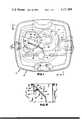
- FIG. 1is a top, plan view of the unique wet/dry vacuum cleaning apparatus in accordance with the present invention
- FIG. 2is a fragmentary, cross-sectional, side elevational view taken generally along line II--II of FIG. 1;
- FIG. 3is a fragmentary, cross-sectional view taken generally along line III--III of FIG. 1;
- FIG. 4is a top, plan view of the suction head of the wet/dry vacuum cleaning apparatus with the cover thereof removed;
- FIG. 5is a bottom, plan view of the suction head
- FIG. 6is a bottom, plan view of the suction head showing the reversing or diverter valve
- FIG. 7is a top, plan view of the collection tank showing the filter bag frame, the tank adapter and the discharge tube;
- FIG. 8is a fragmentary, cross-sectional view taken generally along line VIII--VIII of FIG. 7;
- FIG. 9is a fragmentary, cross-sectional view similar to FIG. 8 illustrating the preferred embodiment of the discharge tube.
- the cleaning apparatusincludes a suction head 12 supported upon an open top collection tank 14.
- the suction head 12includes a molded, integral, one-piece base 16 adapted to rest on the upper, flanged, open end 18 of the tank 14.
- a plurality of handle clamps 20(FIG. 3) each biased by a clamp spring 22 sealingly clamp the base 16 to the tank 14 at molded recesses 24.
- the suction head 12also includes a molded plastic cover 26.
- the cover 26includes a lower peripheral, horizontal flange 28, an outer, depending skirt 30 and an inner depending skirt 32.
- the skirts 30, 32define intake and/or exhaust baffles as will be more fully described below and the cover rests on a peripheral, upstanding wall 34 molded integral with the base 16.
- the base 16defines therein a tank inlet aperture 40, a suction or blower intake aperture 42, a blower exhaust aperture 44 and an atmospheric intake-discharge aperture 46.
- a hose adapter coupling 48is secured to base 16 immediately above and in-line with the tank inlet aperture 40.
- the coupler 48extends through the housing 26 and is adapted to receive an elongated, cleaner hose (not shown) in a conventional fashion.
- Bolted or otherwise suitably secured to the base 16is an electric, motor-fan unit or blower 50.
- the unit 50includes a fan mounted in housing 52 and driven by the output shaft of an electric motor 54.
- the blowerincludes an intake 56 disposed directly above and in line with the aperture 42 formed in the base 16.
- the unit 50includes an exhaust or blower outlet 58 which is connected to and placed in communication with the aperture 44 formed in the base 16 through a plastic or rubber tubing connector 60. This is best seen in FIGS. 2 and 4.
- a wiring panel or control box 62is supported on the base adjacent the hose coupling 48.
- the panel 62includes an on/off switch 64.
- the cover 26is formed with an aperture 66 dimensioned to fit around the panel. Electrical power is supplied to the electric motor 54 through the panel or box 62 via a power cord 68.
- the coverincludes a peripheral sidewall 70 and a top 72. Extending downwardly from the top 72 is an annular structure or skirt 74. Positioned between the top of the motor 54 and the bottom of the annular structure or skirt 74 is a foam, cylindrically shaped gasket 76. A plastic piece 78 is secured to the peripheral wall 70 of the housing and defines therewith a cooling air intake duct or passage 80. Cooling air is conveyed to the motor 54 by passing between the baffles 30, 32 of the housing through the conduit 80 and to the skirt 74 at the top of the motor 54.
- the base 16is fabricated with an integral valve housing generally designated 90.
- the valve housingdefines a valve chamber 92 which is closed at the bottom by a separate plastic plate 94.
- the plate 94may be fabricated or molded with ribs 96 to increase the rigidity thereof.
- the valve housing 90includes sidewalls 96, 98, 100 and 102.
- the circular apertures 42, 44, 46 formed in the basecommunicate with the chamber 92 and the plate 94 defines a circular aperture 104 which communicates with the tank. Therefore, the valve housing 90 including an integral walls 96, 98, 100, 102, the enclosure plate 94 and the base 16 defines a four-ported valve housing.
- valve 106Pivotally mounted within the valve housing and chamber 92 is a vertically positioned, planar diverter or reversing valve 106.
- the valve 106includes a pair of metal retainers 108 of generally rectangular shape. The retainers sandwich therebetween a planar valve member 110.
- the valve member 110is a two-part member formed in two halves from a resilient, sealing material such as gum rubber having a Durometer of 35-45. The retainers 108 are secured together and clamp the halves of the valve member 110 by screws or other suitable fasteners 112.
- Extending vertically from a lower bearing socket 114 defined by the plate 94 through the base 106is a diverter actuator rod 116.
- the actuator rodis secured to the valve element 106 by a pin 118 (FIG. 2) which extends through a cross bore formed adjacent the lower end of the rod 116. Another rod 118 extends through the top 72 of the cover 26. A manually turnable knob 120 is secured to the upper end of rod 118. Rod 118 is secured to the actuator rod 116 by a coupling 122.
- a coil spring 124is positioned concentrically around the rod 116.
- One end 126 of the coil springengages a fixed stop or bolt 130.
- the opposite end 128 of the coil springengages a pin or dowel 130 which extends through a bore formed in the rod 116.
- the coil spring 124biases the valve element 106 to one of two positions.
- the valve housing 90defines a plurality of inwardly directed, vertically extending stops 136, 138 and 140, 142.
- the stops 136, 138abut opposite sides of the valve element 106 when the valve element is in one position and the stops 140, 142 similarly abut opposite sides of the valve element 106 when the valve element is an another position.
- the resilient, sealing members 110 of the valve elementengage the stops providing a seal to prevent cross communication between the chambers defined by the valve housing and the valve element and therefore prevent cross communication between apertures 42, 44, 46 and 104.
- valve element 106when the valve element 106 is in the position shown in FIG. 1, the intake of the blower motor unit 50 will be placed in communication with the interior of the collection tank 14 through the apertures 42 and 104.
- the exhaust outlet of the blower motor unit 50will be placed in communication with atmosphere through the base aperture 44 and the aperture 46.
- a vacuum or suctionwill be created within the collection tank and debris and liquid may be drawn into the tank through the hose (not shown), coupling 48 and the aperture 40.
- the blower motor unitWhen the valve element 106 is shifted to the position shown in solid lines in FIG. 6 wherein it abuts stops 136, 138, the blower motor unit will pressurize the collection tank 14. When in this position, the blower motor intake will be placed in communication with atmosphere through apertures 42, 46 and the valve housing. The blower motor outlet or exhaust will be placed in communication with the tank through aperture 44 in the base and aperture 104 in the housing plate 94. As a result, the tank will pressurize and the liquid and other debris collected therein may be discharged through the aperture or tank inlet 40, the coupling 48 and the hose connected thereto.
- the tank 14supports an adapter plate 150 having a central aperture 152 formed therein.
- a molded, plastic, filter bag frame 154Supported on the adapter plate 150 at the aperture 152 is a molded, plastic, filter bag frame 154.
- the bag frame 154includes a plurality of ribbed sections 156, a base 157 and a peripheral, support flange or shoulder 158.
- the frame 154supports a filter system which is used when the apparatus is employed for dry collection.
- the filter systemincludes an inner bag 160 of Sateen and an outer bag 170 preferably formed of Dacron. The bags are held to the frame by ties 172 adjacent their upper ends.
- the discharge tubeis also, supported on the adapter plate 150.
- the discharge tubeas seen in FIGS. 2, 7 and 8, includes an elongated, tubular portion 178 which is dimensioned to extend to a point adjacent the bottom of the tank.
- One wall 180 of the tubeis angled or sloped from vertical. This wall defines an aperture 182.
- a flapper valve 186Positioned adjacent the aperture 182 on an integral bracket housing 184 is a flapper valve 186.
- the flapper valveincludes a flapper or door 188 having a gasket 190 secured to its innerface and a weight 192 secured to a leg portion 194.
- the flapper valveis pivotally secured at the bracket 184 by a pivot rod 196 and cotter pin 198.
- the discharge tube 176is supported on the adapter plate 150 when the apparatus is employed for wet or liquid collection.
- the flapperWhen the valve element is in the first position and a vacuum is created within the tank, the flapper will pivot in a clockwise direction when viewed in FIG. 8, permitting the debris to enter the tank through the aperture 182.
- the valve elementWhen it is desired to empty the tank, the valve element is shifted to the second position, the pressure within the tank will close the flapper valve and the liquid contained therein will be forced upwardly through the discharge tube 176 and out the aperture 40.
- FIG. 9The presently preferred embodiment of the discharge tube is illustrated in FIG. 9 and generally designated 176'.
- an upper portion 177 of the tube 176' including angled wall 180'is molded integral with the adapter plate 150.
- An elongated tubular portion 178'is molded as a separate piece which slip fits onto the integrally molded portion 177.
- the same flapper valve 186 as in the FIG. 8 embodimentis mounted on wall 180'. This two piece construction simplifies use in the field since only portion 178' need be slipped onto the adapter plate. Also any sealing problems that might develop with the FIG. 8 embodiment are eliminated.
- a float valvegenerally designated 200 and seen in FIGS. 2 and 3, is provided.
- the float valve 200includes a generally cylindrical, open end housing structure 202 which is secured or formed integral with the plate 94 of the valve housing. Supported within the housing 202 is a screen mesh filter 204 and a polyurethane, open cell filter 206. These elements are held within the housing by a ribbed or spoked, generally open plate 208. The plate is held on the housing 202 by spring elements 210. A rod 212 extends downwardly from the center of the plate 208. Slidably supported on the rod 212 is an inverted, cup-shaped float valve element 213.
- the float valve element 213includes a central hub 214 defining a bore for receipt of the rod 212.
- the cupincludes a peripheral wall 216 and a base or top 218. It is presently preferred that the float element 213 be molded from polypropylene having a specific gravity of 0.890 to 0.905, a tensile strength of 2900 to 4500 psi and an elongation of 200% to 700% at break. Such an inverted cup float will float on foam and prevent ingestion of foam into the blower motor should the apparatus be employed for carpet shampooing.
- the undersurface of the base 16is provided with a plurality of spaced bosses 222. Inserted within the bosses 222 are support rods 224.
- the supports rods 224are dimensioned so that the suction head 12 may be removed from a tank and supported on these rods without damage to the float valve 200.
- the filter including the bags 168, 170 and the frame 154is disposed within the aperture 152 of the plate 150.
- the discharge tube 176is removed from the adapter plate 150 (FIG. 8), or the portion 178' is removed (FIG. 9).
- the suction headis then placed on top of the tank 114 and clamped thereto by the clamps 20.
- the valve elementis in the position shown in FIG. 1 and is biased thereto by the spring 124 as previously described.
- the fan motor unitthen creates a suction within the tank and dry debris will be drawn in through the hose coupling 48 and the aperture 40 and collected within the tank.
- the filter and frame assembly 154are removed from the adapter plate 152 and the discharge tube is inserted therein or the portion 178' is slipped onto portion 177.
- the valve element 106is in the position shown in FIG. 1 and liquid and other debris will be collected within the tank 14 by passing through the coupling 48, the aperture 40 and the aperture 182 defined by the discharge tube 176.
- the liquid level within the tankraises the float 213 so that it contacts the plate 208, no liquid or air may be drawn up through the filter 206 or past the screen filter 204 and through the valve housing to the blower unit intake 56.
- the valveis then reversed by rotating the knob 120 and placing the valve element into the position shown in solid lines in FIG. 6.
- the knob 132 on rod 118is provided with a flipable latch 230 which may be pivoted relative thereto and received within a slot (not shown) in the top 72 of the cover 26. This holds the valve 106 in the pumpout or discharge, second position against the bias of the spring.
- a gasket-like material 232be provided around the periphery of the base 16 along a lower surface thereof.
- the gasket material 232is positioned between an outer peripheral flange 234 (FIGS. 2 and 3) and an inner peripheral flange 236.
- a generally planar, L-shaped in cross section baffle plate 238be secured to the upper surface of the base 16.
- the baffle plate 238cooperates with raised walls 240 which extend generally radially outwardly from the atmospheric discharge-intake aperture 46 towards the peripheral wall 34.
- air discharged through aperture 46will contact the walls 240 and the baffle plate 238 and will be directed outwardly around the periphery of the base and the cover through a slot 242 (FIG. 4) formed in the wall 34.
- the skirts 30, 32 formed with the coveralso act as baffles which change the direction and rate of air flow discharging from the cover to thereby reduce the exhaust noise associated therewith.
- the base 16 and the integral diverter valve housing 90be molded from ABS structural foam having a tensile strength at 73° F. of 4000-6000 psi and a flexural yield strength at 73° F. of 7000-10,000 psi.
- the filter 206 at the float housing 202be open cell, polyurethane foam having 40-50 pores per inch and that the metal mesh screen 204 include 4 meshes per inch and be fabricated from a 0.035 diameter wire, galvanized steel wire industrial cloth defining a width opening of 0.215 inches and having 74% open area.
- the diverter valveincluding the housing 90 formed integral with the rigid, structural base 16 substantially reduces the manufacturing cost of the device and also eases the assembly thereof.
- the simple valve 106including the resilient sealing elements 110 which cooperate with the stops 136, 138 and 140, 142 insures reliable operation in service.
- the partsare easily fabricated from plastic using simple molding techniques and are also easily assembled.
- the suction headmay be adapted for use with a variety of different sized tanks, for example, and may be employed with tanks of 40, 50 or 65 liter capacity. The tanks need merely have the same cross-sectional shape at their top in order to receive the suction head.
Landscapes
- Cleaning In General (AREA)
Abstract
Description
Claims (20)
Priority Applications (2)
| Application Number | Priority Date | Filing Date | Title |
|---|---|---|---|
| US05/838,564US4171208A (en) | 1977-10-03 | 1977-10-03 | Vacuum cleaner including diverter valve |
| CA311,045ACA1100716A (en) | 1977-10-03 | 1978-09-11 | Vacuum head including diverter valve |
Applications Claiming Priority (1)
| Application Number | Priority Date | Filing Date | Title |
|---|---|---|---|
| US05/838,564US4171208A (en) | 1977-10-03 | 1977-10-03 | Vacuum cleaner including diverter valve |
Publications (1)
| Publication Number | Publication Date |
|---|---|
| US4171208Atrue US4171208A (en) | 1979-10-16 |
Family
ID=25277440
Family Applications (1)
| Application Number | Title | Priority Date | Filing Date |
|---|---|---|---|
| US05/838,564Expired - LifetimeUS4171208A (en) | 1977-10-03 | 1977-10-03 | Vacuum cleaner including diverter valve |
Country Status (2)
| Country | Link |
|---|---|
| US (1) | US4171208A (en) |
| CA (1) | CA1100716A (en) |
Cited By (36)
| Publication number | Priority date | Publication date | Assignee | Title |
|---|---|---|---|---|
| US4783878A (en)* | 1985-04-08 | 1988-11-15 | Central Quality Industries, Inc. | Vacuum cleaner |
| US4809396A (en)* | 1987-06-29 | 1989-03-07 | Houser Franklin C | Combination vacuum and solution-dispensing apparatus |
| US4841595A (en)* | 1987-08-07 | 1989-06-27 | The Kent Company | Vacuum pump-out system for wet/dry vacuum cleaner |
| US4933017A (en)* | 1987-08-28 | 1990-06-12 | Lemaks Industries, Inc. | Apparatus and method for opening drains |
| US5105504A (en)* | 1987-08-28 | 1992-04-21 | Lemaks Industries, Inc. | Apparatus and method for opening drains |
| US5182834A (en)* | 1992-04-16 | 1993-02-02 | White Consolidated Industries, Inc. | Vacuum pump-out control valve for wet/dry vacuum cleaner |
| US5193245A (en)* | 1987-08-28 | 1993-03-16 | Lemaks Industries, Inc. | Apparatus for opening drains |
| US5263225A (en)* | 1992-03-25 | 1993-11-23 | Winters Richard A | Wet/dry vacuum system |
| US5715568A (en)* | 1995-12-12 | 1998-02-10 | Shop Vac Corporation | Vacuum apparatus having a pump for discharging liquid therefrom |
| US5850668A (en)* | 1996-07-12 | 1998-12-22 | Shop Vac Corporation | Self-evacuating vacuum cleaner |
| US5918344A (en)* | 1996-07-12 | 1999-07-06 | Shop Vac Corporation | Self-evacuating vacuum cleaner |
| US5920955A (en)* | 1996-07-12 | 1999-07-13 | Shop Vac Corporation | Self-evacuating vacuum cleaner |
| US5966775A (en)* | 1996-07-12 | 1999-10-19 | Shop Vac Corporation | Self-evacuating vacuum cleaner |
| US6009596A (en)* | 1996-07-12 | 2000-01-04 | Shop Vac Corporation | Self-evacuating vacuum cleaner |
| US6079076A (en)* | 1997-07-31 | 2000-06-27 | Shop-Vac Corporation | Vacuum cleaner collection bag |
| US6112366A (en)* | 1999-01-20 | 2000-09-05 | Shop Vac Corporation | Outlet priming self-evacuation vacuum cleaner |
| US6219880B1 (en)* | 1998-09-17 | 2001-04-24 | Pullman-Holt Corporation | Vacuum cleaner |
| US6321410B1 (en)* | 1998-08-31 | 2001-11-27 | Emerson Electric Co. | Drum latch retaining mechanism for wet/dry vacuum |
| US6385809B1 (en)* | 2000-03-03 | 2002-05-14 | Emerson Electric Co. | Gasketless wet/dry vacuum with switchable blowing |
| US6453507B1 (en)* | 1999-03-16 | 2002-09-24 | Gene Wilson Gilbert | Self contained, self-cleaning, wet/dry vacuum machine |
| US20050166946A1 (en)* | 2003-11-18 | 2005-08-04 | Amos Stuart R. | Method and apparatus for unclogging flow systems |
| US20080086835A1 (en)* | 2005-04-11 | 2008-04-17 | Alfred Kaercher Gmbh & Co. Kg | Vacuum cleaning device |
| US20080092498A1 (en)* | 2005-04-11 | 2008-04-24 | Alfred Kaercher Gmbh & Co. Kg | Method for cleaning the filters of a vacuum Cleaner and vacuum cleaner for carrying out said method |
| US20090205158A1 (en)* | 2006-07-29 | 2009-08-20 | Alfred Kaercher Gmbh & Co. Kg | Vacuum cleaner |
| US20090205491A1 (en)* | 2006-07-29 | 2009-08-20 | Alfred Kaercher Gmbh & Co. Kg | Method for cleaning the filters of a vacuum cleaner and vacuum cleaner for carrying out the method |
| US20090205499A1 (en)* | 2006-07-29 | 2009-08-20 | Alfred Kaercher Gmbh & Co. Kg | Method for cleaning the filters of a vacuum cleaner and vacuum cleaner for carrying out the method |
| US20090205159A1 (en)* | 2006-07-29 | 2009-08-20 | Alfred Kaercher Gmbh & Co. Kg | Vacuum cleaner |
| US8393048B2 (en) | 2009-04-22 | 2013-03-12 | Alfred Kaercher Gmbh & Co. Kg | Method for cleaning two filters of a suction device for cleaning purposes and suction device for performing the method |
| US8474093B2 (en) | 2009-07-07 | 2013-07-02 | Alfred Kaercher Gmbh & Co. Kg | Suction appliance for cleaning purposes |
| US8510904B2 (en) | 2009-04-30 | 2013-08-20 | Alfred Kaercher Gmbh & Co. Kg | Suction cleaning apparatus |
| US20130255030A1 (en)* | 2012-03-27 | 2013-10-03 | Black & Decker Inc. | Vacuum |
| US20210219801A1 (en)* | 2015-02-02 | 2021-07-22 | Emerson Electric Co. | Vacuum apparatus including float and base-mounted motor |
| US20210259486A1 (en)* | 2006-12-12 | 2021-08-26 | Omachron Intellectual Property Inc. | Upright vacuum cleaner |
| WO2023056834A1 (en)* | 2021-10-08 | 2023-04-13 | 追觅创新科技(苏州)有限公司 | Multi-way joint, and cleaning apparatus |
| US11779175B1 (en) | 2022-12-31 | 2023-10-10 | Thomas Chris Petersen | Apparatus, system and method for vacuum with switchable collection chamber |
| US12239267B2 (en) | 2019-07-02 | 2025-03-04 | Mark Jeffery Giarritta | Four-direction scrubbing carpet shampooer |
Citations (7)
| Publication number | Priority date | Publication date | Assignee | Title |
|---|---|---|---|---|
| GB265965A (en)* | 1926-02-09 | 1927-08-04 | Siemens Schuckertwerke Gmbh | Improvements in or relating to vacuum cleaners |
| US2526212A (en)* | 1946-05-10 | 1950-10-17 | Separator Ab | Vacuum milking system |
| US2643732A (en)* | 1951-09-27 | 1953-06-30 | Continental Car Na Var Corp | Vacuum cleaning machine |
| US3331090A (en)* | 1964-12-01 | 1967-07-18 | Scott Aviation Corp | Liquid suction, storage and discharge device |
| US3516440A (en)* | 1968-02-14 | 1970-06-23 | C H W Inc | Control valve for directing the flow of gases |
| US3605786A (en)* | 1969-09-10 | 1971-09-20 | Purex Corp Ltd | Evacuator |
| US3909219A (en)* | 1973-01-03 | 1975-09-30 | Singer Co | Vacuum cleaner filter assembly |
- 1977
- 1977-10-03USUS05/838,564patent/US4171208A/ennot_activeExpired - Lifetime
- 1978
- 1978-09-11CACA311,045Apatent/CA1100716A/ennot_activeExpired
Patent Citations (7)
| Publication number | Priority date | Publication date | Assignee | Title |
|---|---|---|---|---|
| GB265965A (en)* | 1926-02-09 | 1927-08-04 | Siemens Schuckertwerke Gmbh | Improvements in or relating to vacuum cleaners |
| US2526212A (en)* | 1946-05-10 | 1950-10-17 | Separator Ab | Vacuum milking system |
| US2643732A (en)* | 1951-09-27 | 1953-06-30 | Continental Car Na Var Corp | Vacuum cleaning machine |
| US3331090A (en)* | 1964-12-01 | 1967-07-18 | Scott Aviation Corp | Liquid suction, storage and discharge device |
| US3516440A (en)* | 1968-02-14 | 1970-06-23 | C H W Inc | Control valve for directing the flow of gases |
| US3605786A (en)* | 1969-09-10 | 1971-09-20 | Purex Corp Ltd | Evacuator |
| US3909219A (en)* | 1973-01-03 | 1975-09-30 | Singer Co | Vacuum cleaner filter assembly |
Cited By (52)
| Publication number | Priority date | Publication date | Assignee | Title |
|---|---|---|---|---|
| US4783878A (en)* | 1985-04-08 | 1988-11-15 | Central Quality Industries, Inc. | Vacuum cleaner |
| US4809396A (en)* | 1987-06-29 | 1989-03-07 | Houser Franklin C | Combination vacuum and solution-dispensing apparatus |
| US4841595A (en)* | 1987-08-07 | 1989-06-27 | The Kent Company | Vacuum pump-out system for wet/dry vacuum cleaner |
| US4933017A (en)* | 1987-08-28 | 1990-06-12 | Lemaks Industries, Inc. | Apparatus and method for opening drains |
| US5105504A (en)* | 1987-08-28 | 1992-04-21 | Lemaks Industries, Inc. | Apparatus and method for opening drains |
| US5193245A (en)* | 1987-08-28 | 1993-03-16 | Lemaks Industries, Inc. | Apparatus for opening drains |
| US5263225A (en)* | 1992-03-25 | 1993-11-23 | Winters Richard A | Wet/dry vacuum system |
| US5182834A (en)* | 1992-04-16 | 1993-02-02 | White Consolidated Industries, Inc. | Vacuum pump-out control valve for wet/dry vacuum cleaner |
| US5715568A (en)* | 1995-12-12 | 1998-02-10 | Shop Vac Corporation | Vacuum apparatus having a pump for discharging liquid therefrom |
| US5966775A (en)* | 1996-07-12 | 1999-10-19 | Shop Vac Corporation | Self-evacuating vacuum cleaner |
| US5920955A (en)* | 1996-07-12 | 1999-07-13 | Shop Vac Corporation | Self-evacuating vacuum cleaner |
| US5850668A (en)* | 1996-07-12 | 1998-12-22 | Shop Vac Corporation | Self-evacuating vacuum cleaner |
| US6009596A (en)* | 1996-07-12 | 2000-01-04 | Shop Vac Corporation | Self-evacuating vacuum cleaner |
| US6049940A (en)* | 1996-07-12 | 2000-04-18 | Shop-Vac Corporation | Control circuit for a liquid collecting device |
| US6069330A (en)* | 1996-07-12 | 2000-05-30 | Shop Vac Corporation | Mechanical shut-off and bypass assembly |
| US6347430B1 (en) | 1996-07-12 | 2002-02-19 | Shop Vac Corporation | Self-evacuating vacuum cleaner |
| US5918344A (en)* | 1996-07-12 | 1999-07-06 | Shop Vac Corporation | Self-evacuating vacuum cleaner |
| US6079076A (en)* | 1997-07-31 | 2000-06-27 | Shop-Vac Corporation | Vacuum cleaner collection bag |
| US6321410B1 (en)* | 1998-08-31 | 2001-11-27 | Emerson Electric Co. | Drum latch retaining mechanism for wet/dry vacuum |
| US6219880B1 (en)* | 1998-09-17 | 2001-04-24 | Pullman-Holt Corporation | Vacuum cleaner |
| US6112366A (en)* | 1999-01-20 | 2000-09-05 | Shop Vac Corporation | Outlet priming self-evacuation vacuum cleaner |
| US6453507B1 (en)* | 1999-03-16 | 2002-09-24 | Gene Wilson Gilbert | Self contained, self-cleaning, wet/dry vacuum machine |
| US6385809B1 (en)* | 2000-03-03 | 2002-05-14 | Emerson Electric Co. | Gasketless wet/dry vacuum with switchable blowing |
| US6691396B2 (en)* | 2000-03-03 | 2004-02-17 | Emerson Electric Co. | Wet/dry vacuum and method of assembling same |
| US20050166946A1 (en)* | 2003-11-18 | 2005-08-04 | Amos Stuart R. | Method and apparatus for unclogging flow systems |
| US7160395B2 (en) | 2003-11-18 | 2007-01-09 | Amos Stuart R | Method and apparatus for unclogging flow systems |
| US20080086835A1 (en)* | 2005-04-11 | 2008-04-17 | Alfred Kaercher Gmbh & Co. Kg | Vacuum cleaning device |
| US8186005B2 (en) | 2005-04-11 | 2012-05-29 | Alfred Kaercher Gmbh & Co. Kg | Vacuum cleaning device |
| US20080092498A1 (en)* | 2005-04-11 | 2008-04-24 | Alfred Kaercher Gmbh & Co. Kg | Method for cleaning the filters of a vacuum Cleaner and vacuum cleaner for carrying out said method |
| US7867304B2 (en)* | 2005-04-11 | 2011-01-11 | Alfred Kaercher Gmbh & Co. Kg | Method for cleaning the filters of a vacuum cleaner and vacuum cleaner for carrying out said method |
| US20090205499A1 (en)* | 2006-07-29 | 2009-08-20 | Alfred Kaercher Gmbh & Co. Kg | Method for cleaning the filters of a vacuum cleaner and vacuum cleaner for carrying out the method |
| US20090205159A1 (en)* | 2006-07-29 | 2009-08-20 | Alfred Kaercher Gmbh & Co. Kg | Vacuum cleaner |
| US7861367B2 (en) | 2006-07-29 | 2011-01-04 | Alfred Kaercher Gmbh & Co. Kg | Vacuum cleaner |
| US20090205491A1 (en)* | 2006-07-29 | 2009-08-20 | Alfred Kaercher Gmbh & Co. Kg | Method for cleaning the filters of a vacuum cleaner and vacuum cleaner for carrying out the method |
| US7976614B2 (en) | 2006-07-29 | 2011-07-12 | Alfred Kaercher Gmbh & Co. Kg | Method for cleaning the filters of a vacuum cleaner and vacuum cleaner for carrying out the method |
| US8142554B2 (en) | 2006-07-29 | 2012-03-27 | Alfred Kaercher Gmbh & Co. Kg | Method for cleaning the filters of a vacuum cleaner and vacuum cleaner for carrying out the method |
| US20090205158A1 (en)* | 2006-07-29 | 2009-08-20 | Alfred Kaercher Gmbh & Co. Kg | Vacuum cleaner |
| US20210259486A1 (en)* | 2006-12-12 | 2021-08-26 | Omachron Intellectual Property Inc. | Upright vacuum cleaner |
| US12256882B2 (en)* | 2006-12-12 | 2025-03-25 | Omachron Intellectual Property Inc. | Upright vacuum cleaner |
| US8393048B2 (en) | 2009-04-22 | 2013-03-12 | Alfred Kaercher Gmbh & Co. Kg | Method for cleaning two filters of a suction device for cleaning purposes and suction device for performing the method |
| US8510904B2 (en) | 2009-04-30 | 2013-08-20 | Alfred Kaercher Gmbh & Co. Kg | Suction cleaning apparatus |
| US8474093B2 (en) | 2009-07-07 | 2013-07-02 | Alfred Kaercher Gmbh & Co. Kg | Suction appliance for cleaning purposes |
| US9271620B2 (en)* | 2012-03-27 | 2016-03-01 | Daryl S. Meredith | Vacuum |
| US20160227974A1 (en)* | 2012-03-27 | 2016-08-11 | Black & Decker Inc. | Vacuum |
| US20130255030A1 (en)* | 2012-03-27 | 2013-10-03 | Black & Decker Inc. | Vacuum |
| US20210219801A1 (en)* | 2015-02-02 | 2021-07-22 | Emerson Electric Co. | Vacuum apparatus including float and base-mounted motor |
| US11464379B2 (en)* | 2015-02-02 | 2022-10-11 | Emerson Electric Co. | Vacuum apparatus with interchangeable drums |
| US11819183B2 (en) | 2015-02-02 | 2023-11-21 | Emerson Electric Co. | Vacuum apparatus including drum lock assembly |
| US12011137B2 (en)* | 2015-02-02 | 2024-06-18 | Emerson Electric Co. | Vacuum apparatus including float and base-mounted motor |
| US12239267B2 (en) | 2019-07-02 | 2025-03-04 | Mark Jeffery Giarritta | Four-direction scrubbing carpet shampooer |
| WO2023056834A1 (en)* | 2021-10-08 | 2023-04-13 | 追觅创新科技(苏州)有限公司 | Multi-way joint, and cleaning apparatus |
| US11779175B1 (en) | 2022-12-31 | 2023-10-10 | Thomas Chris Petersen | Apparatus, system and method for vacuum with switchable collection chamber |
Also Published As
| Publication number | Publication date |
|---|---|
| CA1100716A (en) | 1981-05-12 |
Similar Documents
| Publication | Publication Date | Title |
|---|---|---|
| US4171208A (en) | Vacuum cleaner including diverter valve | |
| US5560075A (en) | Wet or dry vacuum with low center of gravity | |
| US5224238A (en) | Horizontal canister vacuum | |
| US5455983A (en) | Wet/dry utility vacuum cleaner | |
| US4467494A (en) | Industrial vacuum cleaner | |
| US4463474A (en) | Vacuum cleaner | |
| US5388301A (en) | Rim seal for vacuum cleaner having dual storage tanks | |
| US4287635A (en) | Wet and dry vacuum cleaner | |
| US4179768A (en) | Vacuum dumping arrangement for a wet/dry vacuum cleaner | |
| US4841595A (en) | Vacuum pump-out system for wet/dry vacuum cleaner | |
| US3877902A (en) | Floor surface treating apparatus | |
| US3308609A (en) | Vacuum cleaning system | |
| US5493752A (en) | Upright carpet and upholstery extractor | |
| EP0012337B1 (en) | Apparatus for cleaning floors, carpets and the like | |
| US3484890A (en) | Pressure-vacuum cleaning and treating device | |
| US5182834A (en) | Vacuum pump-out control valve for wet/dry vacuum cleaner | |
| US20090007367A1 (en) | Attachment device | |
| US3858272A (en) | Vacuum assembly | |
| US5644815A (en) | Sliding door valve for utility vacuum cleaner | |
| US4036346A (en) | Coin operated vacuum apparatus | |
| US5943732A (en) | Door valve for utility vacuum cleaners | |
| US4170805A (en) | Window glass-cleaning device | |
| US2522882A (en) | Vacuum cleaner | |
| US5032155A (en) | Wet/dry vacuum with automatic shutoff | |
| US4010015A (en) | Industrial vacuum cleaner |
Legal Events
| Date | Code | Title | Description |
|---|---|---|---|
| AS | Assignment | Owner name:COOPER INDUSTRIES, INC., 1001 FANNIN, HOUSTON, TEX Free format text:ASSIGNMENT OF ASSIGNORS INTEREST.;ASSIGNOR:MCGRAW-EDISON COMPANY;REEL/FRAME:004475/0965 Effective date:19851104 | |
| AS | Assignment | Owner name:COOPER INDUSTRIES, INC., 1001 FANNIN, SUITE 4000, Free format text:ASSIGNMENT OF ASSIGNORS INTEREST.;ASSIGNOR:COOPER INDUSTRIES, INC., A OH. CORP.;REEL/FRAME:004657/0666 Effective date:19870108 Owner name:COOPER INDUSTRIES, INC., A CORP. OF DE.,TEXAS Free format text:ASSIGNMENT OF ASSIGNORS INTEREST;ASSIGNOR:COOPER INDUSTRIES, INC., A OH. CORP.;REEL/FRAME:004657/0666 Effective date:19870108 | |
| AS | Assignment | Owner name:WELLS FARGO BANK, N.A., STATELESS Free format text:SECURITY INTEREST;ASSIGNOR:CLARKE INDUSTRIES, INC., A CORP. OF DE;REEL/FRAME:006264/0108 Effective date:19920303 | |
| AS | Assignment | Owner name:THERMAL DYNAMICS CORPORATION, MISSOURI Free format text:RELEASE BY SECURED PARTY;ASSIGNOR:WELLS FARGO BANK, N.A.;REEL/FRAME:006865/0170 Effective date:19940201 Owner name:STOODY DELORO STELLITE, INC., MISSOURI Free format text:RELEASE BY SECURED PARTY;ASSIGNOR:WELLS FARGO BANK, N.A.;REEL/FRAME:006865/0170 Effective date:19940201 Owner name:TWECO PRODUCTS, INC., MISSOURI Free format text:RELEASE BY SECURED PARTY;ASSIGNOR:WELLS FARGO BANK, N.A.;REEL/FRAME:006865/0170 Effective date:19940201 Owner name:COYNE CYLINDER COMPANY, MISSOURI Free format text:RELEASE BY SECURED PARTY;ASSIGNOR:WELLS FARGO BANK, N.A.;REEL/FRAME:006865/0170 Effective date:19940201 Owner name:CLARKE INDUSTRIES, INC., MISSOURI Free format text:RELEASE BY SECURED PARTY;ASSIGNOR:WELLS FARGO BANK, N.A.;REEL/FRAME:006865/0170 Effective date:19940201 Owner name:BANKERS TRUST COMPANY, NEW YORK Free format text:SECURITY INTEREST;ASSIGNORS:ARCAIR COMPANY;CLARKE INDUSTRIES, INC.;COYNE CYLINDER COMPANY;AND OTHERS;REEL/FRAME:006865/0142 Effective date:19940201 Owner name:MARISON CYLINDER, MISSOURI Free format text:RELEASE BY SECURED PARTY;ASSIGNOR:WELLS FARGO BANK, N.A.;REEL/FRAME:006865/0170 Effective date:19940201 Owner name:VICTOR EQUIPMENT COMPANY, INC., MISSOURI Free format text:RELEASE BY SECURED PARTY;ASSIGNOR:WELLS FARGO BANK, N.A.;REEL/FRAME:006865/0170 Effective date:19940201 Owner name:ARCAIR COMPANY, MISSOURI Free format text:RELEASE BY SECURED PARTY;ASSIGNOR:WELLS FARGO BANK, N.A.;REEL/FRAME:006865/0170 Effective date:19940201 |