US4158488A - Body-mounted support device for motion picture camera - Google Patents
Body-mounted support device for motion picture cameraDownload PDFInfo
- Publication number
- US4158488A US4158488AUS05/706,196US70619676AUS4158488AUS 4158488 AUS4158488 AUS 4158488AUS 70619676 AUS70619676 AUS 70619676AUS 4158488 AUS4158488 AUS 4158488A
- Authority
- US
- United States
- Prior art keywords
- camera
- tube
- motion picture
- body harness
- arm assemblies
- Prior art date
- Legal status (The legal status is an assumption and is not a legal conclusion. Google has not performed a legal analysis and makes no representation as to the accuracy of the status listed.)
- Expired - Lifetime
Links
Images


Classifications
- F—MECHANICAL ENGINEERING; LIGHTING; HEATING; WEAPONS; BLASTING
- F16—ENGINEERING ELEMENTS AND UNITS; GENERAL MEASURES FOR PRODUCING AND MAINTAINING EFFECTIVE FUNCTIONING OF MACHINES OR INSTALLATIONS; THERMAL INSULATION IN GENERAL
- F16M—FRAMES, CASINGS OR BEDS OF ENGINES, MACHINES OR APPARATUS, NOT SPECIFIC TO ENGINES, MACHINES OR APPARATUS PROVIDED FOR ELSEWHERE; STANDS; SUPPORTS
- F16M11/00—Stands or trestles as supports for apparatus or articles placed thereon ; Stands for scientific apparatus such as gravitational force meters
- F16M11/02—Heads
- F16M11/04—Means for attachment of apparatus; Means allowing adjustment of the apparatus relatively to the stand
- F16M11/06—Means for attachment of apparatus; Means allowing adjustment of the apparatus relatively to the stand allowing pivoting
- F16M11/08—Means for attachment of apparatus; Means allowing adjustment of the apparatus relatively to the stand allowing pivoting around a vertical axis, e.g. panoramic heads
- F—MECHANICAL ENGINEERING; LIGHTING; HEATING; WEAPONS; BLASTING
- F16—ENGINEERING ELEMENTS AND UNITS; GENERAL MEASURES FOR PRODUCING AND MAINTAINING EFFECTIVE FUNCTIONING OF MACHINES OR INSTALLATIONS; THERMAL INSULATION IN GENERAL
- F16M—FRAMES, CASINGS OR BEDS OF ENGINES, MACHINES OR APPARATUS, NOT SPECIFIC TO ENGINES, MACHINES OR APPARATUS PROVIDED FOR ELSEWHERE; STANDS; SUPPORTS
- F16M11/00—Stands or trestles as supports for apparatus or articles placed thereon ; Stands for scientific apparatus such as gravitational force meters
- F16M11/20—Undercarriages with or without wheels
- F16M11/2007—Undercarriages with or without wheels comprising means allowing pivoting adjustment
- F16M11/2035—Undercarriages with or without wheels comprising means allowing pivoting adjustment in more than one direction
- F16M11/2064—Undercarriages with or without wheels comprising means allowing pivoting adjustment in more than one direction for tilting and panning
- F—MECHANICAL ENGINEERING; LIGHTING; HEATING; WEAPONS; BLASTING
- F16—ENGINEERING ELEMENTS AND UNITS; GENERAL MEASURES FOR PRODUCING AND MAINTAINING EFFECTIVE FUNCTIONING OF MACHINES OR INSTALLATIONS; THERMAL INSULATION IN GENERAL
- F16M—FRAMES, CASINGS OR BEDS OF ENGINES, MACHINES OR APPARATUS, NOT SPECIFIC TO ENGINES, MACHINES OR APPARATUS PROVIDED FOR ELSEWHERE; STANDS; SUPPORTS
- F16M11/00—Stands or trestles as supports for apparatus or articles placed thereon ; Stands for scientific apparatus such as gravitational force meters
- F16M11/20—Undercarriages with or without wheels
- F16M11/2092—Undercarriages with or without wheels comprising means allowing depth adjustment, i.e. forward-backward translation of the head relatively to the undercarriage
- F—MECHANICAL ENGINEERING; LIGHTING; HEATING; WEAPONS; BLASTING
- F16—ENGINEERING ELEMENTS AND UNITS; GENERAL MEASURES FOR PRODUCING AND MAINTAINING EFFECTIVE FUNCTIONING OF MACHINES OR INSTALLATIONS; THERMAL INSULATION IN GENERAL
- F16M—FRAMES, CASINGS OR BEDS OF ENGINES, MACHINES OR APPARATUS, NOT SPECIFIC TO ENGINES, MACHINES OR APPARATUS PROVIDED FOR ELSEWHERE; STANDS; SUPPORTS
- F16M11/00—Stands or trestles as supports for apparatus or articles placed thereon ; Stands for scientific apparatus such as gravitational force meters
- F16M11/20—Undercarriages with or without wheels
- F16M11/24—Undercarriages with or without wheels changeable in height or length of legs, also for transport only, e.g. by means of tubes screwed into each other
- F—MECHANICAL ENGINEERING; LIGHTING; HEATING; WEAPONS; BLASTING
- F16—ENGINEERING ELEMENTS AND UNITS; GENERAL MEASURES FOR PRODUCING AND MAINTAINING EFFECTIVE FUNCTIONING OF MACHINES OR INSTALLATIONS; THERMAL INSULATION IN GENERAL
- F16M—FRAMES, CASINGS OR BEDS OF ENGINES, MACHINES OR APPARATUS, NOT SPECIFIC TO ENGINES, MACHINES OR APPARATUS PROVIDED FOR ELSEWHERE; STANDS; SUPPORTS
- F16M13/00—Other supports for positioning apparatus or articles; Means for steadying hand-held apparatus or articles
- F16M13/04—Other supports for positioning apparatus or articles; Means for steadying hand-held apparatus or articles for supporting on, or holding steady relative to, a person, e.g. by chains, e.g. rifle butt or pistol grip supports, supports attached to the chest or head
- F—MECHANICAL ENGINEERING; LIGHTING; HEATING; WEAPONS; BLASTING
- F16—ENGINEERING ELEMENTS AND UNITS; GENERAL MEASURES FOR PRODUCING AND MAINTAINING EFFECTIVE FUNCTIONING OF MACHINES OR INSTALLATIONS; THERMAL INSULATION IN GENERAL
- F16M—FRAMES, CASINGS OR BEDS OF ENGINES, MACHINES OR APPARATUS, NOT SPECIFIC TO ENGINES, MACHINES OR APPARATUS PROVIDED FOR ELSEWHERE; STANDS; SUPPORTS
- F16M2200/00—Details of stands or supports
- F16M2200/04—Balancing means
- F16M2200/044—Balancing means for balancing rotational movement of the undercarriage
- F—MECHANICAL ENGINEERING; LIGHTING; HEATING; WEAPONS; BLASTING
- F16—ENGINEERING ELEMENTS AND UNITS; GENERAL MEASURES FOR PRODUCING AND MAINTAINING EFFECTIVE FUNCTIONING OF MACHINES OR INSTALLATIONS; THERMAL INSULATION IN GENERAL
- F16M—FRAMES, CASINGS OR BEDS OF ENGINES, MACHINES OR APPARATUS, NOT SPECIFIC TO ENGINES, MACHINES OR APPARATUS PROVIDED FOR ELSEWHERE; STANDS; SUPPORTS
- F16M2200/00—Details of stands or supports
- F16M2200/06—Arms
- F16M2200/063—Parallelogram arms
- Y—GENERAL TAGGING OF NEW TECHNOLOGICAL DEVELOPMENTS; GENERAL TAGGING OF CROSS-SECTIONAL TECHNOLOGIES SPANNING OVER SEVERAL SECTIONS OF THE IPC; TECHNICAL SUBJECTS COVERED BY FORMER USPC CROSS-REFERENCE ART COLLECTIONS [XRACs] AND DIGESTS
- Y10—TECHNICAL SUBJECTS COVERED BY FORMER USPC
- Y10S—TECHNICAL SUBJECTS COVERED BY FORMER USPC CROSS-REFERENCE ART COLLECTIONS [XRACs] AND DIGESTS
- Y10S224/00—Package and article carriers
- Y10S224/908—Carrier for camera or other photographic equipment
Definitions
- This inventionrelates to support devices for professional motion picture cameras and is particularly directed to a camera supporting device which may be carried by a cameraman or camera operator or other person, while minimizing the transmission of unwanted movements to the motion picture camera.
- a motion picture camera supported in this manneroften eliminates the need for "dolly" shots, and permits the director to obtain unusual photographic effects such as may be obtained by running up a flight of stairs or running along side a moving vehicle or employing the device to steady the motion picture camera on a moving platform such as a land vehicle, boat or airplane.
- Hand-held motion picture camerashave been used professionally with considerable success, but much depends upon the individual skill and stamina of the camera operator.
- the device of the present inventionrelieves the camera operator of the requirement of supporting in his hands the weight of the motion picture camera assembly, and instead causes the weight of the entire device to be carried on a body harness worn by the operator. He may move about while the motion picture camera "floats" in space, and he uses one hand to aim the camera in the desired direction.
- the motion picture camera assemblyis mounted upon a support tube above a gimbal device, and the battery and possibly the camera motor are carried on the lower end of the support tube well below the gimbal device, to steady the camera against unwanted movements.
- Articulated arms assemblies with pneumatic cushion devicessupport the gimbal device upon the body harness.
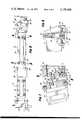
- FIG. 1is a perspective side elevation showing a preferred embodiment of this invention.
- FIG. 2is a top plan view showing a portion of the apparatus.
- FIG. 3is a side elevation partly broken away, showing the articulated arm assemblies for supporting the motion picture camera assembly on the body harness, the parts being shown in extended horizontal position.
- FIG. 4is a view similar to FIG. 3, the parts being shown in elevated position.
- FIG. 5is a sectional detail taken substantially on the lines 5--5 as shown in FIG. 3.
- FIG. 6is a sectional detail taken substantially on the lines 6--6 as shown in FIG. 3.
- FIG. 7is a sectional side elevation showing a portion of the device adjacent the belt of the body harness.
- FIG. 8is a sectional detail taken substantially on the lines 8--8 as shown in FIG. 7.
- FIG. 9is a sectional elevation showing the gimbal device carrying the camera support tube member.
- FIG. 10is a sectional plan view taken substantially on the lines 10--10 as shown in FIG. 9.
- FIG. 11is a sectional elevation taken substantially on the lines 11--11 as shown in FIG. 10.
- FIG. 12is a front elevation partly in section, showing a release mechanism for disconnecting the body harness from the other parts of the device, showing the parts in locked position.
- FIG. 13is a sectional plan view taken substantially on the lines 13--13 as shown in FIG. 12.
- FIG. 14is a view similar to FIG. 12 showing the parts in release position.
- a motion picture camera assemblygenerally designated 10 is mounted on a free-floating support mechanism 11 which includes a camera support tube member 12, battery carrier 13, gimbal device 14, a pair of serially connected articulated arm assemblies 15 and 16, and a body harness 17 which includes a belt 18.
- the body harness 17 and belt 18are proportioned to be worn by a person such as a cameraman or a camera operator.
- the camera base 21is secured to the upper end of the camera support tube member 12 and this tube member 12 is formed of two telescoping parts.
- the upper part 22telescopically receives the lower part 23 by means of a spline joint connection 24.
- the battery carrier 13is fixed at the lower end of the lower tube 23.
- the gimbal device 14includes a ring 24 mounted on bearings 25 carried on clamping sleeve 26.
- the sleeve 26may be clamped at any desired position on the upper part 22 of the camera support tube 12.
- the ring 24includes a pair of diametrically extending trunnions 27 pivotally received in the arms of a yoke 28 having an integral stem 29 extending at right angles to the axis of the aligned trunnions 27.
- the stem 29is received in bearings 30 carried in socket member 32 fixed on the upper end of the upright rod 33.
- a bracket 34is mounted to slide on the rod 33 and may be fixed in any desired position by means of the clamping screw 35.
- the arm assembly 15includes an end member 37, an end member 38, and a pair of links 39 and 40 each pivotally connected to the end members 37 and 38.
- the link 39is pivotally connected to the end member 37 and 41 and is pivotally connected to the end member 38 at 42.
- the link 40is pivotally connected to the end member 37 at 43 and is pivotally connected to end member 38 at 44.
- the construction of the arm assembly 16is similar to that described for the arm assembly 15.
- the end members 46 and 47are each pivotally connected by a pair of links 48 and 49.
- the link 48is pivotally connected to the end member 46 at 50 and is pivotally connected to the end member 47 at 51.
- the link 49is pivotally connected to the end member 46 at 52 and is pivotally connected to the end member 47 at 53.
- the end member 38 of the arm assembly 15is connected to the end member 46 of the arm assembly 16 by means of spaced pivots 55 which are aligned on a vertical axis.
- the pivots 56are aligned on a vertical axis to connect the end member 37 to the bracket 34.
- the end member extension 57, fixed to the end member 47,is connected by aligned vertical pivots 58 to the vertical adjustment block 59.
- the proportions of the parts forming the arm assembly 15 and the arm assembly 16are such that the links and their pivotal connections to their respective end members form parallelograms. Accordingly, the parts may move between the extended horizontal position shown in FIG. 3 and the elevated position shown in FIG. 4.
- Resilient meansare provided for supporting and cushioning the weight of the parts carried on the gimbal device 14 and, as shown in the drawings, this means includes a pneumatic piston-and-cylinder assembly associated with each of the arm assemblies 15 and 16.
- the pneumatic assembly 61has a cylinder portion carrying a socket 62 which engages the ball 63 mounted on the link 40.
- the assembly 61also includes a piston rod 64 provided with a socket 65 which engages a ball 66 carried on the link 39.
- the pneumatic piston-and-cylinder assembly 68has a socket 69 on the cylinder end which engages the ball 70 carried on the link 49.
- the piston rod 71 of the assembly 68carries a socket 72 which engages the ball 73 secured to the link 48.
- the belt 18carries a latch mechanism generally designated 75 at a forward midportion of the belt.
- a curved member 76extends laterally from the latch mechanism 75 around to the left side of the person wearing the belt 18, and this curved member 76 has an end portion 77 near the position of the left hip of the person, and this end portion 77 is provided with a pair of ears 78 which support a threaded adjustment screw 79.
- the adjustment screw 79passes through an internally threaded nut 80 (see FIGS. 7 and 8) which nut 80 carries a cap screw 81 extending at right angles to the axis of the adjustment screw 79.
- the cap screw 81slides within a vertical slot 82 provided in the adjustment block 83.
- This block 83is pivotally mounted with respect to the end portion 77 of curved member 76 by means of the pivot pin 84. From this description it will be understood that turning of the adjusting screw 79 causes the cap screw 81 to swing the block 83 about the horizontal axis of the pivot pin 84.
- the block 59is provided with parallel guide lugs 86 which receive a portion of the block 83 between them in sliding relationship.
- the horizontal pivot pin 87connects the blocks 59 and 83.
- An adjusting screw 88has left-hand and right-hand threads which engage the internally threaded pivot pins 89 and 90 mounted on the blocks 59 and 83, respectively. Turning of the adjusting screw 88 serves to swing the block 59 with respect to the block 83 about the horizontal axis of the pivot pin 87. While both pivot pins 84 and 87 are horizontal, their respective axes are contained in vertical planes which are perpendicular to each other.
- the releasable latch mechanism generally designated 75is best shown in FIGS. 12-14.
- a mounting plate 92is fixed at a central forward position on the belt 18, and a tapered metal block 93 is secured to this mounting plate 92.
- the tapered block 93is received within a receptacle 94 having tapered walls 95.
- Parallel horizontal guide rods 96are fixed within the tapered block 93, and two cross bars 97 are mounted to slide on these guide rods 96.
- Each cross bar 97carries a locking pin 98 which passes through an opening 99 in the tapered block and is received within a locking recess 100 in the receptacle 94.
- the locking pins 98are shown in locked position in FIGS. 12 and are shown in retracted or release position in FIG. 14.
- Meansare provided for actuating the locking pin 98, and, as shown in the drawings, a disk 102 is mounted to turn on a stationary shaft 101 fixed to the mounting plate 92 and to the tapered block 93.
- An actuating lever 103is fixed to the disk 102 and projects upward in front of the body harness 17.
- Pins 104 fixed to the disk 102are carried on the cross bars 97 and project into angular slots 105 formed in the disk 102. Accordingly, manual movement of the actuating lever 103 in a clockwise direction, as viewed in FIGS. 12-14, serves to retract the locking pins 98 from the locking recesses 100, thereby completely disconnecting the tapered block 93 from the receptacle 94.
- the curved member 76 which supports the entire camera support deviceis thus disengaged from the body harness 17. This is an important safety feature, since it enables the person carrying the entire assembly to disengage himself from it instantly, in the event of an emergency, such as, for example, falling into the water. Without this instant disconnect feature, the cameraman or camera operator might be dragged under the water by the weight of the entire assembly, and drowned.
- the battery carrier 13 at the lower end of the part 23 of the camera support tube 12has a section 13a which may be swung laterally about the vertical pivot pin 107.
- This section 13acomprises the battery which supplies power to operate the motion picture camera assembly 10. It may be swung laterally to an adjusted position in order to compensate for any tendency of the camera support tube member to tilt laterally to one side about the gimbal device 14.
- a protective bellows device 108may be provided to enclose the arm assemblies 15 and 16 as a safety measure, as well as to exclude dust and other foreign material.
- a motor 110may be located in the battery carrier 13, if desired, and connected by telescopic drive shafts 111 and 112 to drive the camera mechanism 113 through the belt drive 114.
- the weight of the camera motor 110 at the low position of the battery carrier 13assists in stabilizing the motion picture camera assembly against unwanted rocking movement about the gimbal device 14.
- the drive shaft parts 111 and 112are mounted concentrically within the parts 22 and 23 of the camera support tube member 22.
- the body harness 17is secured in place on the cameraman or camera operator who places his right hand on the grip collar 16 carried on the camera support tube member 12.
- the weight of the motion picture camera assembly 10, battery and battery carrier 13, and associated parts,is resiliently supported on the pneumatic piston-and-cylinder assemblies, and the entire weight is carried on the end portion 77 of the curved member 76.
- the view finder portion of the motion picture camera assembly 10is positioned directly in front of the right eye of the person wearing the body harness. With his right hand he controls the direction of the camera, turning it freely in any direction. With the same hand he may move the tube member 12 and camera assembly 10 in any horizontal direction, including toward and away from the body harness, without changing the force of the springs in the articulated arms.
- His walking or running movementstransmit very little unwanted movement to the camera assembly 10 which tends to "float" in space as he moves about. He may get down on his knees for a low angle shot, in which case the battery carrier 13 rests on the floor or ground, the lower part 23 telescoping up into the upper part 22 of the camera support tube member 12.
- the angular adjustments afforded by the adjusting screw 79 and the adjusting screw 88, the vertical adjustment with respect to the upright rod 33, and the angular adjustment of the battery 13apermit the motion picture camera assembly 10 to be placed in just the right position, and to cause the camera support tube member 12 to remain in vertical position unless tilted by the right hand of the cameraman or camera operator.
- the height of the camera assembly 10may be adjusted by changing the height of the gimbal ring clamp 26 with respect to the upper part 22 of the camera support tube member 12, as well as by changing the position of the bracket 34 with respect to the upright rod 33.
- a video screen device 118may be mounted on the camera assembly 10 in a convenient location for viewing by the operator.
- the operatordoes not attempt to change the focus or aperture while the motion picture camera is operating because this would introduce undesirable movements of the camera assembly 10. Instead, conventional remote control apparatus is provided so that another person may make such changes as are required.
- the person wearing the body harness 17need only aim the camera in the direction desired and hold his right hand as steady as possible while moving about.
Landscapes
- Engineering & Computer Science (AREA)
- General Engineering & Computer Science (AREA)
- Mechanical Engineering (AREA)
- Accessories Of Cameras (AREA)
Abstract
Description
Claims (3)
Priority Applications (18)
| Application Number | Priority Date | Filing Date | Title |
|---|---|---|---|
| US05/706,196US4158488A (en) | 1976-07-19 | 1976-07-19 | Body-mounted support device for motion picture camera |
| US05/740,781US4158489A (en) | 1976-07-19 | 1976-11-11 | Body-mounted camera support apparatus |
| GB27037/77AGB1543296A (en) | 1976-07-19 | 1977-06-28 | Body-mounted support device for motion picture camera |
| AU26626/77AAU508066B2 (en) | 1976-07-19 | 1977-06-30 | Camera support |
| IL52439AIL52439A (en) | 1976-07-19 | 1977-07-01 | Body-mounted support device for motion picture camera |
| CA282,148ACA1087012A (en) | 1976-07-19 | 1977-07-06 | Body-mounted support device for a camera |
| SE7707924ASE426992B (en) | 1976-07-19 | 1977-07-07 | The body-worn support for a camera |
| FR7721699AFR2359361A1 (en) | 1976-07-19 | 1977-07-13 | DEVICE ALLOWING AN OPERATOR TO CARRY A CINEMATOGRAPHIC CAMERA |
| ITRM1977A50299AIT7750299A1 (en) | 1976-07-19 | 1977-07-15 | Body-mounted support device for motion picture cameras |
| JP8516277AJPS5312616A (en) | 1976-07-19 | 1977-07-18 | Device for supporting body |
| DE19772732847DE2732847A1 (en) | 1976-07-19 | 1977-07-18 | BODY-MOUNTED SUPPORT DEVICE FOR CINEMA FILM CAMERAS |
| CH888277ACH617994A5 (en) | 1976-07-19 | 1977-07-18 | Camera carrying device |
| MX169883AMX144618A (en) | 1976-07-19 | 1977-07-18 | IMPROVEMENTS IN SUPPORT FOR MOVIE AND TELEVISION CAMERAS MOUNTED IN THE BODY |
| CS774812ACS207713B2 (en) | 1976-07-19 | 1977-07-19 | Body carrying device for the camera |
| NLAANVRAGE7708045,ANL171488C (en) | 1976-07-19 | 1977-07-19 | SUPPORT DEVICE FOR A FILM OR TELEVISION CAMERA CARRIED OUT BY THE HULL OF THE BODY. |
| JP11262580AJPS5643879A (en) | 1976-07-19 | 1980-08-15 | Camera support |
| JP11262480AJPS5642473A (en) | 1976-07-19 | 1980-08-15 | Camera support |
| HK518/81AHK51881A (en) | 1976-07-19 | 1981-10-29 | Body-mounted support device for motion picture camera |
Applications Claiming Priority (1)
| Application Number | Priority Date | Filing Date | Title |
|---|---|---|---|
| US05/706,196US4158488A (en) | 1976-07-19 | 1976-07-19 | Body-mounted support device for motion picture camera |
Related Child Applications (1)
| Application Number | Title | Priority Date | Filing Date |
|---|---|---|---|
| US05/740,781Continuation-In-PartUS4158489A (en) | 1976-07-19 | 1976-11-11 | Body-mounted camera support apparatus |
Publications (1)
| Publication Number | Publication Date |
|---|---|
| US4158488Atrue US4158488A (en) | 1979-06-19 |
Family
ID=24836594
Family Applications (2)
| Application Number | Title | Priority Date | Filing Date |
|---|---|---|---|
| US05/706,196Expired - LifetimeUS4158488A (en) | 1976-07-19 | 1976-07-19 | Body-mounted support device for motion picture camera |
| US05/740,781Expired - LifetimeUS4158489A (en) | 1976-07-19 | 1976-11-11 | Body-mounted camera support apparatus |
Family Applications After (1)
| Application Number | Title | Priority Date | Filing Date |
|---|---|---|---|
| US05/740,781Expired - LifetimeUS4158489A (en) | 1976-07-19 | 1976-11-11 | Body-mounted camera support apparatus |
Country Status (3)
| Country | Link |
|---|---|
| US (2) | US4158488A (en) |
| JP (2) | JPS5643879A (en) |
| IT (1) | IT7750299A1 (en) |
Cited By (22)
| Publication number | Priority date | Publication date | Assignee | Title |
|---|---|---|---|---|
| US4290684A (en)* | 1980-01-24 | 1981-09-22 | Eastman Kodak Company | Image stabilizing apparatus |
| US4474439A (en)* | 1982-01-26 | 1984-10-02 | Brown Garrett W | Camera support |
| US4774589A (en)* | 1986-03-03 | 1988-09-27 | Rowland David A | Optical system image stabilizer employing electromechanical torque sensors |
| US4991758A (en)* | 1989-09-22 | 1991-02-12 | Eaneff Charles S | Support system for portable video camera |
| US5005030A (en)* | 1990-05-29 | 1991-04-02 | Wells David L | Hand held camera steadying device |
| US5289090A (en)* | 1991-05-09 | 1994-02-22 | Miller Jeffrey E | Automatic camcorder panning device |
| US5360196A (en)* | 1992-09-15 | 1994-11-01 | Garrett W. Brown | Adjustable, iso-elastic support apparatus |
| US5435515A (en)* | 1992-09-15 | 1995-07-25 | Garrett W. Brown | Adustable, iso-elastic support apparatus |
| US5579071A (en)* | 1994-03-21 | 1996-11-26 | Garrett W. Brown | Camera stabilizing support |
| US5797054A (en)* | 1995-06-09 | 1998-08-18 | Paddock; George K. | Three axis gimbal for use in a camera support system |
| US5963749A (en)* | 1998-02-09 | 1999-10-05 | Nicholson; Lynn | Self-leveling invertible camera stabilizer |
| US6068223A (en)* | 1997-11-25 | 2000-05-30 | Panavision, Inc. | Position adjustable grip support for motion picture camera |
| WO2000073027A2 (en) | 1999-05-10 | 2000-12-07 | Innovative Office Products, Inc. | Arm apparatus for mounting electronic devices |
| WO2003023274A1 (en)* | 2001-09-13 | 2003-03-20 | Sachtler Gmbh & Co. Kg | Cardanic suspension device for a camera balance device |
| US20050053371A1 (en)* | 2001-09-13 | 2005-03-10 | Schaller Curt O. | Decoupled weight compensation system for a camera balance-device |
| FR2870317A1 (en)* | 2004-05-11 | 2005-11-18 | Planning Camera Sarl | Camera stabilization device for use in cinema field, has two expanding parallelograms mounted on both sides of central block, where each parallelogram has gas spring, and pressure inside spring is variable |
| US20060263082A1 (en)* | 2005-04-15 | 2006-11-23 | Brown Garrett W | Equipoising support apparatus |
| US7677515B2 (en) | 2004-07-07 | 2010-03-16 | Innovative Office Products, Inc. | Arm apparatus with reinforcement |
| US20110114684A1 (en)* | 2009-11-16 | 2011-05-19 | Plasan Sasa Ltd. | Load carrying system |
| US20130087588A1 (en)* | 2010-05-31 | 2013-04-11 | Ulrich Kahlert | Support, holding, and/or carrying apparatus |
| WO2016164438A1 (en)* | 2015-04-07 | 2016-10-13 | Brown Garrett W | Balancing support interface for payload stabilizers |
| US9736376B1 (en) | 2014-04-03 | 2017-08-15 | The Tiffen Company, Llc | Tilt head, camera stage, multi-post monitor mount and camera stabilizer encompassing the same |
Families Citing this family (29)
| Publication number | Priority date | Publication date | Assignee | Title |
|---|---|---|---|---|
| US4298149A (en)* | 1978-01-17 | 1981-11-03 | Panavision, Incorporated | Body harness for cinematographer |
| US4222540A (en)* | 1978-12-01 | 1980-09-16 | Westinghouse Electric Corp. | Tube sheet pan and tilt camera platform |
| FR2530357A1 (en)* | 1982-07-15 | 1984-01-20 | Cinaction | DEVICE FOR CONTROLLING REMOTE CONTROL OF THE POSITION OF A MOBILE HOLDER |
| AU573558B2 (en)* | 1982-12-01 | 1988-06-16 | Brown, Garrett | Suspension system for supporting and conveying a camera assembly |
| JPS60115487A (en)* | 1983-11-29 | 1985-06-21 | Konishiroku Photo Ind Co Ltd | Thermal transfer recording medium |
| US4685649A (en)* | 1984-07-19 | 1987-08-11 | Gregory Gault | Vibration isolator camera mount |
| US4621785A (en)* | 1984-11-23 | 1986-11-11 | Embra Productions Ltd. | Camera mount |
| DE3645246C2 (en)* | 1986-12-16 | 1997-10-09 | Kreuzer Friedhelm Gmbh | Load support with derricking boom |
| DE3642955C1 (en)* | 1986-12-16 | 1988-06-23 | Kreuzer Friedhelm Gmbh | Tripod with a column |
| US4836478A (en)* | 1987-10-15 | 1989-06-06 | Ergotron, Inc. | Suspension system for personal computers and monitors |
| US5229798A (en)* | 1988-09-22 | 1993-07-20 | Brown Garrett W | Stabilized equipment support, primarily for use with hand-held cameras |
| US5737657A (en)* | 1995-11-17 | 1998-04-07 | Paddock; George K. | Adjustable platform having a quick release mechanism for use with a camera |
| US5687943A (en)* | 1996-01-19 | 1997-11-18 | Campbell; Pleasant W. | Apparatus for supporting a video camera and cable above a work surface |
| USD386510S (en)* | 1996-03-11 | 1997-11-18 | Peterson Thomas K M | Telescoping monopod gun and camera support |
| WO1998044287A1 (en)* | 1997-03-28 | 1998-10-08 | Thieltges Gary P | Motion stable camera support system |
| US6155764A (en)* | 1999-04-05 | 2000-12-05 | Russo; Angelo | Support for wearing on the torso and supporting and raising a ceiling panel |
| US7371028B2 (en)* | 2003-05-01 | 2008-05-13 | George Paddock Ii, Inc. | Post mounting system |
| US7681846B1 (en)* | 2003-07-23 | 2010-03-23 | Vladan Mijailovic | Steadying camera support platform |
| US7199832B2 (en)* | 2004-10-01 | 2007-04-03 | Daniel Oran | Portable photographic device and grip with integrated controls for single handed use |
| CA2605034C (en)* | 2005-04-15 | 2012-07-10 | Garrett W. Brown | Folding and adjusting hinge for stabilized equipment support |
| USD670752S1 (en) | 2008-09-18 | 2012-11-13 | Edward Barber | Portable camera mount |
| US7891621B1 (en) | 2009-10-28 | 2011-02-22 | General Electric Company | Mounting apparatus in support of a device from a platform |
| KR20120107714A (en)* | 2011-03-22 | 2012-10-04 | 삼성테크윈 주식회사 | Multi-linkage and multi-tree structure system and method for controlling the same |
| WO2014107574A1 (en) | 2013-01-04 | 2014-07-10 | Brown Garrett W | Folding image stabilizer |
| US9417509B2 (en) | 2013-03-15 | 2016-08-16 | Cam Caddie | Universal stabilizing camera mount apparatus |
| US9769360B2 (en) | 2015-03-23 | 2017-09-19 | Harry Potter Investments Llc | Camera rig |
| CN112377565A (en)* | 2020-11-29 | 2021-02-19 | 中国船舶重工集团公司七五0试验场 | Monitoring and warning device for preventing fishing of offshore oil platform |
| US11774038B2 (en)* | 2021-06-08 | 2023-10-03 | Christian J West | Mounting assembly |
| EP4258015A1 (en)* | 2022-04-08 | 2023-10-11 | Faro Technologies, Inc. | Support system for mobile coordinate scanner |
Citations (7)
| Publication number | Priority date | Publication date | Assignee | Title |
|---|---|---|---|---|
| US568977A (en)* | 1896-10-06 | Bicycle-seat | ||
| US817207A (en)* | 1905-10-19 | 1906-04-10 | Harold L Wheeler | Camera-support. |
| US2007215A (en)* | 1931-11-12 | 1935-07-09 | John T Remey | Stabilized vibration absorbing mounting |
| DE1187504B (en)* | 1960-03-31 | 1965-02-18 | Eicher Traktor Landmasch | Spring-loaded driver's seat for tractor |
| US3215386A (en)* | 1964-04-10 | 1965-11-02 | Milsco Mfg Co | Pneumatic seat support |
| US3409261A (en)* | 1966-11-07 | 1968-11-05 | Visual Systems Inc | Counterpoising or equipoising mechanism |
| US4017168A (en)* | 1974-09-16 | 1977-04-12 | Brown Garrett W | Equipment for use with hand held motion picture cameras |
Family Cites Families (1)
| Publication number | Priority date | Publication date | Assignee | Title |
|---|---|---|---|---|
| US2753778A (en)* | 1953-06-01 | 1956-07-10 | Fred C Daiss | Adjustable camera support |
- 1976
- 1976-07-19USUS05/706,196patent/US4158488A/ennot_activeExpired - Lifetime
- 1976-11-11USUS05/740,781patent/US4158489A/ennot_activeExpired - Lifetime
- 1977
- 1977-07-15ITITRM1977A50299Apatent/IT7750299A1/enunknown
- 1980
- 1980-08-15JPJP11262580Apatent/JPS5643879A/enactivePending
- 1980-08-15JPJP11262480Apatent/JPS5642473A/enactivePending
Patent Citations (7)
| Publication number | Priority date | Publication date | Assignee | Title |
|---|---|---|---|---|
| US568977A (en)* | 1896-10-06 | Bicycle-seat | ||
| US817207A (en)* | 1905-10-19 | 1906-04-10 | Harold L Wheeler | Camera-support. |
| US2007215A (en)* | 1931-11-12 | 1935-07-09 | John T Remey | Stabilized vibration absorbing mounting |
| DE1187504B (en)* | 1960-03-31 | 1965-02-18 | Eicher Traktor Landmasch | Spring-loaded driver's seat for tractor |
| US3215386A (en)* | 1964-04-10 | 1965-11-02 | Milsco Mfg Co | Pneumatic seat support |
| US3409261A (en)* | 1966-11-07 | 1968-11-05 | Visual Systems Inc | Counterpoising or equipoising mechanism |
| US4017168A (en)* | 1974-09-16 | 1977-04-12 | Brown Garrett W | Equipment for use with hand held motion picture cameras |
Cited By (32)
| Publication number | Priority date | Publication date | Assignee | Title |
|---|---|---|---|---|
| US4290684A (en)* | 1980-01-24 | 1981-09-22 | Eastman Kodak Company | Image stabilizing apparatus |
| US4474439A (en)* | 1982-01-26 | 1984-10-02 | Brown Garrett W | Camera support |
| US4774589A (en)* | 1986-03-03 | 1988-09-27 | Rowland David A | Optical system image stabilizer employing electromechanical torque sensors |
| US4991758A (en)* | 1989-09-22 | 1991-02-12 | Eaneff Charles S | Support system for portable video camera |
| US5005030A (en)* | 1990-05-29 | 1991-04-02 | Wells David L | Hand held camera steadying device |
| US5289090A (en)* | 1991-05-09 | 1994-02-22 | Miller Jeffrey E | Automatic camcorder panning device |
| US5360196A (en)* | 1992-09-15 | 1994-11-01 | Garrett W. Brown | Adjustable, iso-elastic support apparatus |
| US5435515A (en)* | 1992-09-15 | 1995-07-25 | Garrett W. Brown | Adustable, iso-elastic support apparatus |
| US5579071A (en)* | 1994-03-21 | 1996-11-26 | Garrett W. Brown | Camera stabilizing support |
| US5797054A (en)* | 1995-06-09 | 1998-08-18 | Paddock; George K. | Three axis gimbal for use in a camera support system |
| US6068223A (en)* | 1997-11-25 | 2000-05-30 | Panavision, Inc. | Position adjustable grip support for motion picture camera |
| US5963749A (en)* | 1998-02-09 | 1999-10-05 | Nicholson; Lynn | Self-leveling invertible camera stabilizer |
| WO2000073027A2 (en) | 1999-05-10 | 2000-12-07 | Innovative Office Products, Inc. | Arm apparatus for mounting electronic devices |
| EP1337726A4 (en)* | 1999-05-10 | 2006-08-23 | Innovative Office Products Inc | Arm apparatus for mounting electronic devices |
| WO2003023274A1 (en)* | 2001-09-13 | 2003-03-20 | Sachtler Gmbh & Co. Kg | Cardanic suspension device for a camera balance device |
| US20050031336A1 (en)* | 2001-09-13 | 2005-02-10 | Schaller Curt O | Cardanic suspension device for a camera balance device |
| US20050053371A1 (en)* | 2001-09-13 | 2005-03-10 | Schaller Curt O. | Decoupled weight compensation system for a camera balance-device |
| AU2002325953B2 (en)* | 2001-09-13 | 2008-01-10 | Camera Dynamics Gmbh | Cardanic suspension device for a camera balance device |
| US7390131B2 (en)* | 2001-09-13 | 2008-06-24 | Camera Dynamics Gmbh | Decoupled weight compensation system for a camera balance-device |
| US7192203B2 (en)* | 2001-09-13 | 2007-03-20 | Schaller Curt O | Cardanic suspension device for a camera balance device |
| FR2870317A1 (en)* | 2004-05-11 | 2005-11-18 | Planning Camera Sarl | Camera stabilization device for use in cinema field, has two expanding parallelograms mounted on both sides of central block, where each parallelogram has gas spring, and pressure inside spring is variable |
| US7677515B2 (en) | 2004-07-07 | 2010-03-16 | Innovative Office Products, Inc. | Arm apparatus with reinforcement |
| US20060263082A1 (en)* | 2005-04-15 | 2006-11-23 | Brown Garrett W | Equipoising support apparatus |
| US7618016B2 (en) | 2005-04-15 | 2009-11-17 | Brown Garrett W | Equipoising support apparatus |
| US20100059652A1 (en)* | 2005-04-15 | 2010-03-11 | Brown Garrett W | Equipoising support apparatus |
| US8066251B2 (en) | 2005-04-15 | 2011-11-29 | Brown Garrett W | Equipoising support apparatus |
| US20110114684A1 (en)* | 2009-11-16 | 2011-05-19 | Plasan Sasa Ltd. | Load carrying system |
| US20130087588A1 (en)* | 2010-05-31 | 2013-04-11 | Ulrich Kahlert | Support, holding, and/or carrying apparatus |
| US9254564B2 (en)* | 2010-05-31 | 2016-02-09 | Ulrich Kahlert | Support, holding, and/or carrying apparatus |
| US9736376B1 (en) | 2014-04-03 | 2017-08-15 | The Tiffen Company, Llc | Tilt head, camera stage, multi-post monitor mount and camera stabilizer encompassing the same |
| WO2016164438A1 (en)* | 2015-04-07 | 2016-10-13 | Brown Garrett W | Balancing support interface for payload stabilizers |
| CN107407863A (en)* | 2015-04-07 | 2017-11-28 | 加勒特·W·布朗 | Balanced support interface for load stabilizers |
Also Published As
| Publication number | Publication date |
|---|---|
| JPS5643879A (en) | 1981-04-22 |
| US4158489A (en) | 1979-06-19 |
| JPS5642473A (en) | 1981-04-20 |
| IT7750299A1 (en) | 1979-01-15 |
Similar Documents
| Publication | Publication Date | Title |
|---|---|---|
| US4158488A (en) | Body-mounted support device for motion picture camera | |
| US4158490A (en) | Body-mounted support device for motion picture camera | |
| US4156512A (en) | Equipment support system | |
| EP2283646B1 (en) | Apparatus for support and movement of a camera | |
| US4206983A (en) | Camera stabilizing body mount | |
| US3352521A (en) | Universal mount | |
| US4685649A (en) | Vibration isolator camera mount | |
| US5742859A (en) | Camera support and stabilizing device | |
| JP4204436B2 (en) | Shoulder-mounted camera support device for fixing camera or video camera | |
| US7563038B2 (en) | Support for a camcorder | |
| US4474439A (en) | Camera support | |
| US6056449A (en) | Frame assembly for supporting a camera | |
| US4327986A (en) | Mobile camera support | |
| US8506180B2 (en) | Extendable camera support and stabilization apparatus | |
| US6685148B2 (en) | Support for hand held video camera | |
| US8029197B2 (en) | Hand-held image stabilization and balancing system for cameras | |
| US10921689B2 (en) | Enhanced camera positioner | |
| US6068223A (en) | Position adjustable grip support for motion picture camera | |
| CS207713B2 (en) | Body carrying device for the camera | |
| US4542966A (en) | Shoulder-hand support for photographic apparatus | |
| US3044346A (en) | Universally adjustable camera support for a vehicle | |
| US20040223078A1 (en) | Support for hand held video camera | |
| US9519203B1 (en) | Quick-reposition camera support | |
| US20100264283A1 (en) | Support for compact video camera | |
| CA1132392A (en) | Body-mounted support for low elevation camera |
Legal Events
| Date | Code | Title | Description |
|---|---|---|---|
| AS | Assignment | Owner name:PV ACQUISITION CORP., LOS ANGELES, CA. A DE CORP. Free format text:ASSIGNMENT OF ASSIGNORS INTEREST.;ASSIGNOR:PANAVISION, INC. A CA CORP.;REEL/FRAME:004372/0600 Effective date:19850221 | |
| AS | Assignment | Owner name:PANAVISION, INCORPORATED Free format text:CHANGE OF NAME;ASSIGNOR:PV ACQUISITION CORP.;REEL/FRAME:004382/0185 Effective date:19850306 | |
| AS | Assignment | Owner name:FIRST NATIONAL BANK OF BOSTON, THE, 100 FEDERAL ST Free format text:SECURITY INTEREST;ASSIGNOR:PV ACQUISITION CORP.;REEL/FRAME:004382/0323 Effective date:19850301 | |
| AS | Assignment | Owner name:CITICORP INDUSTRIAL CREDIT, INC., 725 SOUTH FIGUER Free format text:SECURITY INTEREST;ASSIGNOR:PANAVISION, INCORPORATED;REEL/FRAME:004801/0160 Effective date:19871013 | |
| AS | Assignment | Owner name:PANAVISION, INC. Free format text:ASSIGNMENT OF ASSIGNORS INTEREST.;ASSIGNOR:FIRST NATIONAL BANK OF BOSTON, THE;REEL/FRAME:004812/0400 Effective date:19871009 | |
| AS | Assignment | Owner name:CITICORP NORTH AMERICA, INC., (FORMERLY CITICORP I Free format text:SECURITY INTEREST;ASSIGNOR:PANAVISION, INCORPORATED;REEL/FRAME:004869/0502 Effective date:19880217 Owner name:CITICORP NORTH AMERICA, INC. (FORMERLY CITICORP IN Free format text:SECURITY INTEREST;ASSIGNOR:PANAVISION, INCORPORATED;REEL/FRAME:004869/0502 Effective date:19880217 | |
| AS | Assignment | Owner name:WESTWARD COMMUNICATIONS PUBLIC LIMITED COMPANY Free format text:RELEASE OF SECURITY AGREEMENT RECORDED AT REEL 4869, FRAME 502.;ASSIGNOR:CITICORP NORTH AMERICA, INC., F/K/A CITICORP INDUSTRIAL CREDIT, INC.;REEL/FRAME:005810/0087 Effective date:19910801 Owner name:LEE INTERNATIONAL LIMITED, A PRIVATE LIMITED COMPA Free format text:THE RELEASE OF SECURITY AGREEMENT ON REEL 4801, FRAME 160.;ASSIGNOR:CITICORP NORTH AMERICA, INC.;REEL/FRAME:005810/0082 Effective date:19910801 Owner name:CITICORP NORTH AMERICA, INC. Free format text:SECURITY INTEREST;ASSIGNOR:PANAVISION INTERNATIONAL, L.P., A LIMITED PARTNERSHIP OF DE;REEL/FRAME:005810/0092 Effective date:19910601 | |
| AS | Assignment | Owner name:PANAVISION INTERNATIONAL, L.P., NEW YORK Free format text:ASSIGNMENT OF ASSIGNORS INTEREST.;ASSIGNOR:PANAVISION, INCORPORATED;REEL/FRAME:005863/0832 Effective date:19910930 | |
| AS | Assignment | Owner name:PANAVISION INTERNATIONAL, L.P., NEW YORK Free format text:RELEASE OF SECURITY INTEREST;ASSIGNOR:CITICORP NORTH AMERICA, INC.;REEL/FRAME:008792/0908 Effective date:19960508 |