US4155206A - Insulated metal roofing system - Google Patents
Insulated metal roofing systemDownload PDFInfo
- Publication number
- US4155206A US4155206AUS05/897,671US89767178AUS4155206AUS 4155206 AUS4155206 AUS 4155206AUS 89767178 AUS89767178 AUS 89767178AUS 4155206 AUS4155206 AUS 4155206A
- Authority
- US
- United States
- Prior art keywords
- roofing
- legs
- members
- ceiling
- panels
- Prior art date
- Legal status (The legal status is an assumption and is not a legal conclusion. Google has not performed a legal analysis and makes no representation as to the accuracy of the status listed.)
- Expired - Lifetime
Links
- 229910052751metalInorganic materials0.000titleclaimsabstractdescription16
- 239000002184metalSubstances0.000titleclaimsabstractdescription15
- 238000009413insulationMethods0.000claimsabstractdescription16
- 239000000725suspensionSubstances0.000claimsdescription22
- 239000000463materialSubstances0.000claimsdescription11
- 238000009434installationMethods0.000claimsdescription4
- 230000000149penetrating effectEffects0.000claims4
- 238000010276constructionMethods0.000description7
- 229920003023plasticPolymers0.000description5
- 239000004033plasticSubstances0.000description5
- 230000000694effectsEffects0.000description3
- 229920000915polyvinyl chloridePolymers0.000description3
- 239000004800polyvinyl chlorideSubstances0.000description3
- 230000005494condensationEffects0.000description2
- 238000009833condensationMethods0.000description2
- 239000004020conductorSubstances0.000description2
- 241000288673ChiropteraSpecies0.000description1
- 229910000831SteelInorganic materials0.000description1
- 229910052782aluminiumInorganic materials0.000description1
- XAGFODPZIPBFFR-UHFFFAOYSA-NaluminiumChemical compound[Al]XAGFODPZIPBFFR-UHFFFAOYSA-N0.000description1
- 239000011324beadSubstances0.000description1
- 239000002131composite materialSubstances0.000description1
- 239000004035construction materialSubstances0.000description1
- 238000000034methodMethods0.000description1
- 239000011347resinSubstances0.000description1
- 229920005989resinPolymers0.000description1
- 239000010959steelSubstances0.000description1
- 239000013589supplementSubstances0.000description1
- 239000012780transparent materialSubstances0.000description1
Images

Classifications
- E—FIXED CONSTRUCTIONS
- E04—BUILDING
- E04D—ROOF COVERINGS; SKY-LIGHTS; GUTTERS; ROOF-WORKING TOOLS
- E04D3/00—Roof covering by making use of flat or curved slabs or stiff sheets
- E04D3/36—Connecting; Fastening
- E04D3/361—Connecting; Fastening by specially-profiled marginal portions of the slabs or sheets
- E04D3/362—Connecting; Fastening by specially-profiled marginal portions of the slabs or sheets by locking the edge of one slab or sheet within the profiled marginal portion of the adjacent slab or sheet, e.g. using separate connecting elements
- E—FIXED CONSTRUCTIONS
- E04—BUILDING
- E04D—ROOF COVERINGS; SKY-LIGHTS; GUTTERS; ROOF-WORKING TOOLS
- E04D13/00—Special arrangements or devices in connection with roof coverings; Protection against birds; Roof drainage ; Sky-lights
- E04D13/16—Insulating devices or arrangements in so far as the roof covering is concerned, e.g. characterised by the material or composition of the roof insulating material or its integration in the roof structure
- E04D13/1606—Insulation of the roof covering characterised by its integration in the roof structure
- E04D13/1643—Insulation of the roof covering characterised by its integration in the roof structure the roof structure being formed by load bearing corrugated sheets, e.g. profiled sheet metal roofs
- E04D13/165—Double skin roofs
- E—FIXED CONSTRUCTIONS
- E04—BUILDING
- E04D—ROOF COVERINGS; SKY-LIGHTS; GUTTERS; ROOF-WORKING TOOLS
- E04D3/00—Roof covering by making use of flat or curved slabs or stiff sheets
- E04D3/24—Roof covering by making use of flat or curved slabs or stiff sheets with special cross-section, e.g. with corrugations on both sides, with ribs, flanges, or the like
- E04D3/30—Roof covering by making use of flat or curved slabs or stiff sheets with special cross-section, e.g. with corrugations on both sides, with ribs, flanges, or the like of metal
Definitions
- Add-on roomssuch as sun rooms
- Some add-on roomsamount to little more than covered patios with sidewalls added.
- the more rudimentary the construction of an add-on roomthe lower its utility is, because such simply constructed rooms are not comfortable in very hot or moderately cold weather, and cannot be heated or cooled efficiently.
- Another limitation of such rooms, when they are constructed of metal panels,is that objectionable condensation tends to form on the interior ceiling and walls when the inside air is warm and humid and the outside temperature is cold.
- the present inventionrelates to a multi-part panel type insulated roof system which is particularly useful in add-on room construction, although the system is also useful in other building situations.
- Various composite or insulated metal roofing and siding systemsare known in the art which bear some superficial resemblance to the system of the invention; e.g. U.S. Pat. Nos. 2,007,374; 3,304,680; 3,479,784; and 2,602,526; but none of these has the flexibility of application of the invention nor its particular utility in the add-on field.
- an insulated metal roofing systemwhich, in its preferred forms, involves four components which cooperate to provide an integrated roof and ceiling which is weather-tight, energy efficient, easily installed, and economical.
- the preferred systemsthus include interlocking channel shaped roofing members, suspension clips attached to and depending from the roofing members, generally channel shaped ceiling members attached to the suspension clips and spaced below the roofing members, and insulative material interposed in the space between the roofing members and the ceiling members.
- the suspension clipsmay be omitted and replaced by marginal ceiling support members, and such members may also be used to supplement the suspension clips in larger rooms.
- the clipsare omitted altogether, and the ceiling panels are connected directly to the roofing members.
- the roofing membersare generally channel shaped elongated panels, with the legs of the channels being upstanding and extending along the edges of the bases of the channels.
- the roofing membersare preferably formed of sheet metal, such as aluminum or steel, with the legs of the channel integral with the base.
- the upper margins of the channel legsare developed or formed into interlocking joint elements, preferably of the kind in which two panels are interlocked by rotating one panel with respect to the other. In their interlocked positions, adjacent panels have their upstanding legs in abutting relationship.
- the upstanding legs of the roofing membersare provided with detents for cooperation with the special suspension clips utilized in some embodiments of the invention, and with ceiling panels in another form of the invention, as is explained more fully hereinbelow.
- one of two forms of suspension clipis used to connect the ceiling panels to the roofing member.
- Both formsare preferably made of plastic such as polyvinyl chloride, which is strong and durable, yet a poor conductor of heat.
- One form of clipis generally H-shaped in profile, with the bar of the "H” having a length substantially equal to the width of a roofing member.
- the upstanding legs of the "H”are adapted to fit between abutting upstanding channel legs of adjacent connected roofing members, and are provided with flanges along their top edges for engaging the abovementioned detents in the roofing member channel legs.
- the bar of the "H”lies along the underside of the roofing member. Because of the "springiness" of the H-shaped clip configuration when rendered in plastic, the bar of the "H” tends to urge the flanges of the upstanding legs more securely into the detents of the roofing member.
- the "springiness" of the clipis enhanced by configuring the bar of the "H” to include a vertical depending flange.
- the depending legs of the H-shaped clipare provided with at least one set of outwardly and downwardly extending flanges which terminate in detents for forming connections with ceiling panels as is discussed below.
- the depending legsare provided with a plurality of sets of such flanges spaced at selected distances along the height of the legs. In this manner provision is made to selectively vary the spacing between roofing members and ceiling panels.
- the other form of suspension clipwhich may be utilized in accordance with the invention is generally I-shaped in profile, with a flange or other connecting means at the top of the "I" for engaging the detent in a roofing member channel wall, and with at least one set of outwardly and downwardly extending flanges terminating in detents. Again, it is preferred that a plurality of such sets be provided so that the spacing between roofing members and ceiling panels may be selectively varied.
- the ceiling panels of the inventionare generally channel shaped elongated elements having a width substantially equal to the width of a roofing member, or if desired, some multiple of that width.
- the upstanding legs or sidewalls of the ceiling channelshave flanges at their top edges for snap-locking engagement with detents on the suspension clips or alternately with the detents on the roofing panel.
- the space between the roofing members and the ceiling panelsis preferably filled with insulation, which may be in loose form, or in rolls or bats, or plastic slabs or other forms. It is less satisfactory, but the dead air space between the roofing members and the ceiling panels may itself be relied upon to provide some insulating effect.
- a principal object of the present inventionis the provision of an improved insulated metal roofing system which is simple in construction and installation, and flexible in arrangement.
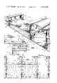
- FIG. 1is an end perspective view of an insulated metal roofing system constructed in accordance with the invention
- FIG. 2is an end elevational view of an insulated metal roofing system much like that of FIG. 1, but with a thicker layer of insulation being provided;
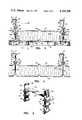
- FIG. 3is an end elevational view of another embodiment of the roofing system of the invention, utilizing a different form of suspension clip;
- FIG. 4is an end elevational view of still another embodiment of the invention, in which the suspension clips are omitted and the ceiling members are connected directly to the roofing members;
- FIG. 5is a perspective view of an H-shaped suspension clip constructed in accordance with the invention.
- FIG. 6is a side sectional elevational view of the roofing system of FIG. 3, the section being taken on the line 6--6 of FIG. 3;
- FIG. 7is an end elevational view of an insulated metal roofing system much like that of FIGS. 1 and 2, but having an intermediate thickness of insulation, utilizing a modified form of H-shaped clip, and further utilizing a modified form of detent in the ciling panels;
- FIG. 8is a perspective view of the clip utilized in the embodiment of FIG. 7.
- FIGS. 1, 2 and 5Attention is first directed to FIGS. 1, 2 and 5.
- the amount of insulation needed in an insulated roofing systemvaries from installation to installation, depending upon the part of the country in which the roof is being built, the desired degree of insulating efficiency, local building codes, and similar factors.
- FIGS. 1 and 2The roofing system illustrated in FIGS. 1 and 2 has this desired flexibility.
- FIG. 1shows a roof with a modest amount of insulation therein, enough to retard moisture condensation on the ceiling, but not enough to prevent heavy heat loss in a severe climate.
- FIG. 2shows the same metal and plastic parts assembled into a roof with a very deep layer of insulation therein, enough to satisfy even a very demanding building code or owner's specification.
- the ability of the roofing system to accomodate different thicknesses of insulationis provided in large measure by the clip illustrated in FIG. 5.
- the roofing system of the inventionis designated generally as 10. It includes a series of generally channel shaped roofing members 11, 12, 13, 14, arranged to lie parallel to each other in side-by-side relationship. (The skylight structure of FIGS. 1 and 2 is discussed herein below, and may be ignored for present purposes.)
- the roofing membersare supported at their ends by the walls of the structure being roofed, or by suitable beams, neither of which are shown in FIGS. 1 and 2.
- the roofing members 11-14are each provided with upstanding walls or legs, the left-hand leg of each such panel being designated 15 and the right-hand leg 16.
- the upper edges of legs 15, 16are developed into interlocking curled flanges 17, 18, respectively.
- adjacent panelsmay be locked together in side-by-side relationship with their upstanding legs 15, 16, in abutting relationship, and with curled flange 17 overlying and curling around curled flange 18.
- Flanges 17 and 18 of adjacent panelsmay best be interlocked together by rotating panel 13 with respect to already installed panel 12, for example.
- curled flange 17has a detent 19 formed therein where it joins leg 15, which mates with similarly positioned detent 20 on curled flange 18.
- curled flange 18has a depression 21 formed on its upper surface, which may accomodate a bead of caulking to insure watertightness of the joint.
- the base of the channel of the roofing membermay have one or more grooves 22 formed therein to provide longitudinal stiffening, and the junctions between the base of the channel and legs 15, 16, may be beveled, as at 23, 24.
- Legs 15 and 16have opposed detents 25, 26 formed therein near their junctions with the base of the channel of the roofing member. These are engaged by suspension clips 27.
- clip 27can best be understood from a consideration of FIG. 5.
- the clipis generally H-shaped, having a bar 28, upstanding legs 29, 30, and depending legs 31, 32.
- the bar 28has a length substantially equal to the width of a roofing member.
- Upstanding legs 29, 30have inwardly and downwardly projecting flanges 33 and 34 formed at their top edges, for engagement with the detents 25, 26 in the roofing members.
- the depending legs 31, 32have three sets of ceiling panel engaging elements 35 formed thereon.
- Each set of ceiling panel engaging elements 35comprises an outwardly and downwardly extending flange 36, terminating in a detent 37, and an opposed inwardly and downwardly extending flange 38, terminating in a detent 39.
- Clip 27is preferably formed of a resilient plastic material, such as polyvinyl chloride, which is a poor conductor of heat. As can be seen from FIG. 5, the clip is relatively short or narrow, although it may have any desired length, even being coextensive in length with the ceiling member, if desired. Preferably, for economy of material, short clips are employed, and are spaced along a roofing member at intervals of several feet.
- the suspension clip 27is connected to a roofing member, such as 13, with flanges 33, 34, snap-locked into detents 25, 26.
- the bar 28 of the cliplies along the underside of the roofing member, and assists in maintaining the parts in connected position by reason of the springiness of the material.
- the suspension clip 27is installed in the configuration shown in FIG. 5. But if a closer spacing is needed, one or two sets of ceiling panel engaging elements are cut off each depending leg of the clip.
- the cliphas been foreshortened so that the uppermost set of ceiling panel engaging elements is the one employed to engage the ceiling panel.
- one set of ceiling panel engaging elementshas been cut off the clip to provide an intermediate thickness of insulation.
- the ceiling panels of the inventionare generally channel shaped elongated metal elements designated 38 in the drawings.
- the base of the channelmay have a groove 39 formed therein for longitudinal stiffening, and the junctions of the legs and base of the channel may be beveled, as at 40, 41.
- the grooves and bevelsalso provide a decorative effect on the underside of the ceiling.
- the legs or sidewalls of the channelare designated 42, 43, and are provided with downwardly and inwardly extending flanges 44, 45 along their top edges for snap-locked engagement with detents 37 of the clip 27.
- legs 42, 43are each offset inwardly a small amount a short distance above the junction bevels 40, 41 as at 46, 47 so that when two ceiling panels are placed in abutting relationship, there is formed between them a narrow upwardly open slot in which the end portion of depending leg 31 or 32 of suspension clip 27 fits.
- a layer of insulation(indicated very diagrammatically at 48) is installed between the ceiling panels and the roofing members. Desirably, substantially the entire space is so filled, but it need not be.
- the roofing system illustrated in FIGS. 1 and 2may be easily installed at the construction site, using a basic one-panel-at-a-time approach.
- a workerinstalls roofing panels from left to right as FIGS. 1 and 2 are drawn, pivoting each succeeding panel around the curled flange of its already installed neighbor to the left to interlock them together in abutting relationship.
- the H-shaped clipsare preferably installed on every other roofing panel prior to pivoting it into place.
- the ceiling panelsare then snapped onto the clips from below, from left to right, either one at a time or in small groups.
- the insulationmay be installed in each ceiling panel just prior to putting the panel in place, or it may be installed earlier, even at the factory.
- the roofing members, ceiling panels and insulationall have basically the same structure and mode of operation, and the parts are therefore given the same reference characters as were employed in connection with FIGS. 1 and 2. Reference is made to the foregoing discussion for an understanding of these parts.
- the clip employed in the embodiment of FIGS. 3 and 6differs from that employed in the embodiment of FIGS. 1 and 2 in that it is I-shaped rather than H-shaped, and is desirably installed after a pair of roofing panels are locked together rather than before.
- the I-shaped clipsare designated 49.
- the structure of clips 49is substantially like that of upstanding leg 30 and depending leg 32 of clip 27 shown in FIG. 5. Clips 49 engage the roofing members and ceiling panels in substantially the same manner as clips 27.
- FIGS. 3 and 6also show an L-shaped perimeter support member 50, which is attached to room side wall 51 by screws 52, and to the underside of the ceiling panels by screws 53.
- Support member 49thus has its vertical leg 54 in abuttment with the room wall, while its horizontal leg 55 is cantilevered outwardly to provide support to the ceiling panels.
- perimeter support membersalone may be adequate to support the ceiling panels, and the clips may be omitted.
- the roofing members and the insulationhave substantially the same structure as in the embodiment of FIGS. 1-3, and are therefore given the same reference characters.
- the ceiling panels 56 of FIG. 4differ from ceiling panels 38 in other embodiments in that their upwardly extending legs 57, 58 are relatively longer, so that they may be detent locked directly to the roofing members at the detents formed therein. To that end, legs 57, 58, have downwardly and inwardly projecting flanges 60, 61, formed at their upper edges.
- the embodiment of FIG. 4has the advantage of requiring fewer parts than the other embodiments, but there is some metal-to-metal contact between the ceiling panel and the roofing members.
- FIGS. 1 and 2illustrate the features of the invention that make it possible to include a skylight in the roofing system quite readily.
- a roofing member 13is omitted from the side-by-side series of such members, and is replaced by a translucent skylight roofing member 62, preferably formed of polyvinyl chloride resin, or some other suitable translucent or transparent material.
- Translucent member 62is provided with a first pair of downwardly extending flanges 63, 64, for engaging curled flange 18, and a second pair of downwardly extending flanges 65, 66, for engaging curled flange 17.
- Flange 63has an inwardly turned detent lip 67
- flange 64has an outwardly turned detent lip 68, for snap-lock engagement with curled flange 18.
- flange 65has an outwardly and upwardly turned detent lip 69 for locking engagement with curled flange 17.
- skylight roofing member 62is arched in profile to enhance its stiffness.
- the skylight structureincludes support strips 70. These strips have substantially the same profile as the edge portions of the ceiling panels. Thus each strip has a vertical leg 71 which terminates in a downturned flange 72 for detent locking with a clip 27; and bevel section 73; and a horizontal leg 74. A translucent or transparent panel 75 is supported by the legs 74, and may be readily removed, if desired, by tilting it to work it past legs 74.
- FIGS. 7 and 8show a roofing system modified in certain respects from those discussed above. Unchanged parts and features are given the same reference characters, while modified parts are given equivalent characters with primes added.
- detents 25', 26'have flattened bottoms to enhance the detent locking effect.
- Flanges 33', 34' of clip 27'are somewhat thickened to correspond with the altered shape of the detent.
- bar 28' of clip 27'has a downturned lip or flange to increase its stiffness and thus the springiness of the clip.
Landscapes
- Engineering & Computer Science (AREA)
- Architecture (AREA)
- Civil Engineering (AREA)
- Structural Engineering (AREA)
- Mechanical Engineering (AREA)
- Roof Covering Using Slabs Or Stiff Sheets (AREA)
Abstract
Description
Claims (15)
Priority Applications (1)
| Application Number | Priority Date | Filing Date | Title |
|---|---|---|---|
| US05/897,671US4155206A (en) | 1978-04-19 | 1978-04-19 | Insulated metal roofing system |
Applications Claiming Priority (1)
| Application Number | Priority Date | Filing Date | Title |
|---|---|---|---|
| US05/897,671US4155206A (en) | 1978-04-19 | 1978-04-19 | Insulated metal roofing system |
Publications (1)
| Publication Number | Publication Date |
|---|---|
| US4155206Atrue US4155206A (en) | 1979-05-22 |
Family
ID=25408235
Family Applications (1)
| Application Number | Title | Priority Date | Filing Date |
|---|---|---|---|
| US05/897,671Expired - LifetimeUS4155206A (en) | 1978-04-19 | 1978-04-19 | Insulated metal roofing system |
Country Status (1)
| Country | Link |
|---|---|
| US (1) | US4155206A (en) |
Cited By (59)
| Publication number | Priority date | Publication date | Assignee | Title |
|---|---|---|---|---|
| EP0029277A1 (en)* | 1979-11-15 | 1981-05-27 | Redland-Braas-Bredero Europa (R.B.B.) B.V. | Roof or wall construction, provided with heat- and/or sound insulation panels |
| US4299070A (en)* | 1978-06-30 | 1981-11-10 | Heinrich Oltmanns | Box formed building panel of extruded plastic |
| US4389823A (en)* | 1981-06-28 | 1983-06-28 | Howmet Aluminum Corporation | Modular roof skylight |
| US4423572A (en) | 1980-09-22 | 1984-01-03 | Tor Edward S | Water-tight insulated roof construction for house |
| US4425747A (en) | 1981-06-22 | 1984-01-17 | Howmet Aluminum Corp. | Twin-vee ceiling hanger clip |
| US4463537A (en)* | 1982-01-29 | 1984-08-07 | Integrated Ceilings, Inc. | Clip for suspending ceiling panels |
| US4463533A (en)* | 1982-06-24 | 1984-08-07 | Mullet Willis J | Sheet material roofing panel |
| US4476659A (en)* | 1981-06-22 | 1984-10-16 | Player Wayne H | Insulated roofing system with slidable roof to ceiling clips |
| US4522007A (en)* | 1983-11-17 | 1985-06-11 | Oehlert James A | Interlocking building panel |
| US4671038A (en)* | 1986-04-30 | 1987-06-09 | Porter William H | Roof sandwich panel juncture running with the pitch |
| US4791770A (en)* | 1985-11-01 | 1988-12-20 | Amca International Corporation | Subpurlin and attachment assembly |
| US4811475A (en)* | 1987-07-29 | 1989-03-14 | Jodac, Inc. | Plant hanger |
| EP0275145A3 (en)* | 1987-01-10 | 1989-04-05 | Crozier Construction Co. Limited | Cladding for buildings |
| US4833844A (en)* | 1984-03-29 | 1989-05-30 | Per Wiklund | Roof construction |
| US4918898A (en)* | 1989-02-07 | 1990-04-24 | Mcleod Jr John D | Building panel |
| US4936078A (en)* | 1988-12-02 | 1990-06-26 | Porter William H | Interconnecting panels |
| US4991370A (en)* | 1989-01-11 | 1991-02-12 | Alcan Aluminum Corporation | Security panel system |
| US5020293A (en)* | 1989-01-27 | 1991-06-04 | Tamatoshi Industries Limited | Decorative panel assembly |
| US5125204A (en)* | 1990-05-14 | 1992-06-30 | Porter William H | Snap-in panel mounting arrangement |
| US5179746A (en)* | 1991-09-23 | 1993-01-19 | Rogers D Randall | Stretcher |
| US5230192A (en)* | 1991-11-26 | 1993-07-27 | W. P. Hickman Company | Ventilated roofing system |
| US5394664A (en)* | 1993-10-12 | 1995-03-07 | Patio Encolsures, Inc. | Interlocking skylight and roof panel assembly |
| US5413300A (en)* | 1992-05-13 | 1995-05-09 | Hosteing; Guy | Profiles for supporting and maintaining in tension a false ceiling or a false wall |
| US5737891A (en)* | 1996-05-17 | 1998-04-14 | Crown Partnership | Channel-mounted interlocking panel roofing structure |
| US5737892A (en)* | 1996-05-17 | 1998-04-14 | Crown Partnership | Channel-mounted interlocking panel roofing structure |
| US6212829B1 (en) | 2000-04-06 | 2001-04-10 | W. P. Hickman Company | Coping assembly for building roof |
| US6257565B1 (en) | 2000-01-26 | 2001-07-10 | Cherokee Metals Company | Decking clamp and method of making the same |
| US6360504B1 (en) | 2000-04-06 | 2002-03-26 | W. P. Hickman Company | Coping assembly for building roof |
| US20040163351A1 (en)* | 2003-02-20 | 2004-08-26 | Rodney Rood | Standing seam roof and method of manufacturing same |
| US20040164476A1 (en)* | 2002-12-06 | 2004-08-26 | Carnell A. Boyd | Secured threading nut decking clamp and method for making same |
| US6786018B2 (en) | 2000-04-06 | 2004-09-07 | W. P. Hickman Company | Coping or fascia assembly for building roof |
| US20060059808A1 (en)* | 2004-09-23 | 2006-03-23 | Nguyen Hung T | Prefabricated universal structural steel panel and panel system |
| US20060179764A1 (en)* | 2005-01-27 | 2006-08-17 | Nichiha Co., Ltd. | Siding boards attachment structure |
| US7571571B1 (en)* | 2008-02-08 | 2009-08-11 | Megawall Corporation | Slatwall profile |
| US20100162643A1 (en)* | 2008-10-02 | 2010-07-01 | Blomberg Jerome O | Curbless multiple skylight and smoke vent system |
| US20110179739A1 (en)* | 2003-06-27 | 2011-07-28 | Konvin Associates Limited Partnership | Light Transmission Panels, Retaining Clip and a Combination Thereof |
| US8438799B2 (en) | 2008-10-02 | 2013-05-14 | T&M Inventions, Llc | Support structures on roofs |
| US8438801B2 (en) | 2011-03-14 | 2013-05-14 | T&M Inventions, Llc | Support structures on roofs |
| US8438800B2 (en) | 2011-03-14 | 2013-05-14 | T&M Inventions, Llc | Support structures on roofs |
| US8438798B2 (en) | 2008-10-02 | 2013-05-14 | T&M Inventions, Llc | Roof penetrating closure structures and systems |
| US20130118109A1 (en)* | 2010-08-03 | 2013-05-16 | Hch Spolka Z.O.O. | System of construction elements for the dry construction of structures |
| US8701362B2 (en) | 2011-01-14 | 2014-04-22 | Extech Building Materials | Skylight with thermal break |
| US9032671B1 (en) | 2014-01-17 | 2015-05-19 | T&M Inventions, Llc | Support structure using extended-length diverter |
| US9127461B2 (en) | 2011-04-14 | 2015-09-08 | T&M Inventions, Llc | Thermal barrier about roof support structure |
| US9347220B1 (en)* | 2014-11-14 | 2016-05-24 | Awi Licensing Llc | Ceiling system |
| US9534390B2 (en) | 2013-03-15 | 2017-01-03 | T&M Inventions, Llc | Support structures on roofs |
| US9556613B1 (en) | 2016-05-24 | 2017-01-31 | Awi Licensing Llc | Ceiling system |
| US9637927B2 (en) | 2011-04-14 | 2017-05-02 | T&M Inventions, Llc | Diverter |
| US9677279B2 (en) | 2011-04-14 | 2017-06-13 | T&M Inventions, Llc | Condensation control in a roof mounted load support structure |
| US20170183875A1 (en)* | 2015-12-23 | 2017-06-29 | Certainteed Corporation | System, method and apparatus for thermal bridge-free insulation assembly |
| USD837038S1 (en) | 2017-03-31 | 2019-01-01 | Certainteed Corporation | Insulation hanger |
| US10267039B2 (en) | 2012-09-04 | 2019-04-23 | Awi Licensing Llc | Ceiling systems |
| US10323410B2 (en) | 2016-09-30 | 2019-06-18 | Certainteed Corporation | Systems, methods, and apparatuses for insulating adjacent to a top of an attic |
| US10352048B2 (en) | 2016-10-13 | 2019-07-16 | T&M Inventions, Llc | Load support structure for use on roof |
| US10358820B2 (en)* | 2014-06-23 | 2019-07-23 | Nordic Build A/S | Modular building system and a method of assembling building elements to construct such building system |
| US11155997B2 (en)* | 2017-01-02 | 2021-10-26 | Sabic Global Technologies B.V. | Roof forming element, roof, and method of manufacturing |
| US11293178B2 (en) | 2012-09-04 | 2022-04-05 | Awi Licensing Llc | Ceiling systems |
| US20230014278A1 (en)* | 2020-09-21 | 2023-01-19 | Alain Perez | Multi-purpose structural panels and systems for assembling structures |
| US12203271B1 (en)* | 2022-09-09 | 2025-01-21 | Jim T. Daniels | Metal roofing system |
Citations (20)
| Publication number | Priority date | Publication date | Assignee | Title |
|---|---|---|---|---|
| US2007374A (en)* | 1932-07-25 | 1935-07-09 | United States Gypsum Co | Acoustical roof deck |
| US2602526A (en)* | 1949-04-19 | 1952-07-08 | Hobart M Day | Building construction |
| US2662745A (en)* | 1949-10-12 | 1953-12-15 | Burgess Manning Co | Radiant panel heating and and air distributing structure |
| GB769526A (en)* | 1952-12-16 | 1957-03-06 | William Cookson | Improvements in or relating to roofing and sí¡í¡ sheets |
| DK99829C (en)* | 1962-01-10 | 1964-09-21 | Tage Oskar Harald Vilhel Bille | Ceiling or wall cladding. |
| US3238681A (en)* | 1963-03-07 | 1966-03-08 | Ircom S P A | Structural members of sheet material for walls, roofings, floors and the like |
| US3245187A (en)* | 1963-09-20 | 1966-04-12 | May David | Roof structure |
| US3289375A (en)* | 1964-05-07 | 1966-12-06 | Cline Aluminum Products Inc | Panel construction |
| US3304680A (en)* | 1963-12-13 | 1967-02-21 | Anel Engineering Ind Inc | Interlocking structural system for buildings |
| AT252522B (en)* | 1965-06-18 | 1967-02-27 | Ove Andreas Jorgensen | Spring-loaded holder for hanging removable ceiling cladding elements |
| DE1509136A1 (en)* | 1962-02-19 | 1969-05-22 | Schraml Dipl Ing Helmuth | Roof element serving as skylights |
| US3479784A (en)* | 1967-12-05 | 1969-11-25 | Tru Lok Metal Fabricating Co I | Construction panel |
| US3488905A (en)* | 1967-12-29 | 1970-01-13 | William C Campbell | Building roof structure |
| US3524289A (en)* | 1968-07-25 | 1970-08-18 | Kaufmann Window & Door Corp | Awning construction |
| US3608267A (en)* | 1970-05-14 | 1971-09-28 | Robertson Co H H | Floor structure and building construction panel therefor |
| DE2149828A1 (en)* | 1970-10-15 | 1972-04-20 | Portaels Albert P | Profile for creating a metal skeleton |
| US3732659A (en)* | 1971-04-27 | 1973-05-15 | Pittsburh Aluminum | Adjustable locking assembly |
| US3992839A (en)* | 1974-11-21 | 1976-11-23 | Ethyl Corporation | Snap-on paneling |
| US4038799A (en)* | 1975-04-30 | 1977-08-02 | Frigitemp Corporation | Joiner bulkhead method and apparatus |
| US4046408A (en)* | 1973-08-03 | 1977-09-06 | Steven Ausnit | Omni-directional fastener |
- 1978
- 1978-04-19USUS05/897,671patent/US4155206A/ennot_activeExpired - Lifetime
Patent Citations (20)
| Publication number | Priority date | Publication date | Assignee | Title |
|---|---|---|---|---|
| US2007374A (en)* | 1932-07-25 | 1935-07-09 | United States Gypsum Co | Acoustical roof deck |
| US2602526A (en)* | 1949-04-19 | 1952-07-08 | Hobart M Day | Building construction |
| US2662745A (en)* | 1949-10-12 | 1953-12-15 | Burgess Manning Co | Radiant panel heating and and air distributing structure |
| GB769526A (en)* | 1952-12-16 | 1957-03-06 | William Cookson | Improvements in or relating to roofing and sí¡í¡ sheets |
| DK99829C (en)* | 1962-01-10 | 1964-09-21 | Tage Oskar Harald Vilhel Bille | Ceiling or wall cladding. |
| DE1509136A1 (en)* | 1962-02-19 | 1969-05-22 | Schraml Dipl Ing Helmuth | Roof element serving as skylights |
| US3238681A (en)* | 1963-03-07 | 1966-03-08 | Ircom S P A | Structural members of sheet material for walls, roofings, floors and the like |
| US3245187A (en)* | 1963-09-20 | 1966-04-12 | May David | Roof structure |
| US3304680A (en)* | 1963-12-13 | 1967-02-21 | Anel Engineering Ind Inc | Interlocking structural system for buildings |
| US3289375A (en)* | 1964-05-07 | 1966-12-06 | Cline Aluminum Products Inc | Panel construction |
| AT252522B (en)* | 1965-06-18 | 1967-02-27 | Ove Andreas Jorgensen | Spring-loaded holder for hanging removable ceiling cladding elements |
| US3479784A (en)* | 1967-12-05 | 1969-11-25 | Tru Lok Metal Fabricating Co I | Construction panel |
| US3488905A (en)* | 1967-12-29 | 1970-01-13 | William C Campbell | Building roof structure |
| US3524289A (en)* | 1968-07-25 | 1970-08-18 | Kaufmann Window & Door Corp | Awning construction |
| US3608267A (en)* | 1970-05-14 | 1971-09-28 | Robertson Co H H | Floor structure and building construction panel therefor |
| DE2149828A1 (en)* | 1970-10-15 | 1972-04-20 | Portaels Albert P | Profile for creating a metal skeleton |
| US3732659A (en)* | 1971-04-27 | 1973-05-15 | Pittsburh Aluminum | Adjustable locking assembly |
| US4046408A (en)* | 1973-08-03 | 1977-09-06 | Steven Ausnit | Omni-directional fastener |
| US3992839A (en)* | 1974-11-21 | 1976-11-23 | Ethyl Corporation | Snap-on paneling |
| US4038799A (en)* | 1975-04-30 | 1977-08-02 | Frigitemp Corporation | Joiner bulkhead method and apparatus |
Cited By (85)
| Publication number | Priority date | Publication date | Assignee | Title |
|---|---|---|---|---|
| US4299070A (en)* | 1978-06-30 | 1981-11-10 | Heinrich Oltmanns | Box formed building panel of extruded plastic |
| EP0029277A1 (en)* | 1979-11-15 | 1981-05-27 | Redland-Braas-Bredero Europa (R.B.B.) B.V. | Roof or wall construction, provided with heat- and/or sound insulation panels |
| US4423572A (en) | 1980-09-22 | 1984-01-03 | Tor Edward S | Water-tight insulated roof construction for house |
| US4425747A (en) | 1981-06-22 | 1984-01-17 | Howmet Aluminum Corp. | Twin-vee ceiling hanger clip |
| US4476659A (en)* | 1981-06-22 | 1984-10-16 | Player Wayne H | Insulated roofing system with slidable roof to ceiling clips |
| US4389823A (en)* | 1981-06-28 | 1983-06-28 | Howmet Aluminum Corporation | Modular roof skylight |
| US4463537A (en)* | 1982-01-29 | 1984-08-07 | Integrated Ceilings, Inc. | Clip for suspending ceiling panels |
| US4463533A (en)* | 1982-06-24 | 1984-08-07 | Mullet Willis J | Sheet material roofing panel |
| US4522007A (en)* | 1983-11-17 | 1985-06-11 | Oehlert James A | Interlocking building panel |
| US4833844A (en)* | 1984-03-29 | 1989-05-30 | Per Wiklund | Roof construction |
| US4791770A (en)* | 1985-11-01 | 1988-12-20 | Amca International Corporation | Subpurlin and attachment assembly |
| US4671038A (en)* | 1986-04-30 | 1987-06-09 | Porter William H | Roof sandwich panel juncture running with the pitch |
| EP0275145A3 (en)* | 1987-01-10 | 1989-04-05 | Crozier Construction Co. Limited | Cladding for buildings |
| US4811475A (en)* | 1987-07-29 | 1989-03-14 | Jodac, Inc. | Plant hanger |
| US4936078A (en)* | 1988-12-02 | 1990-06-26 | Porter William H | Interconnecting panels |
| US4991370A (en)* | 1989-01-11 | 1991-02-12 | Alcan Aluminum Corporation | Security panel system |
| US5020293A (en)* | 1989-01-27 | 1991-06-04 | Tamatoshi Industries Limited | Decorative panel assembly |
| US4918898A (en)* | 1989-02-07 | 1990-04-24 | Mcleod Jr John D | Building panel |
| US5125204A (en)* | 1990-05-14 | 1992-06-30 | Porter William H | Snap-in panel mounting arrangement |
| US5179746A (en)* | 1991-09-23 | 1993-01-19 | Rogers D Randall | Stretcher |
| US5230192A (en)* | 1991-11-26 | 1993-07-27 | W. P. Hickman Company | Ventilated roofing system |
| US5413300A (en)* | 1992-05-13 | 1995-05-09 | Hosteing; Guy | Profiles for supporting and maintaining in tension a false ceiling or a false wall |
| US5394664A (en)* | 1993-10-12 | 1995-03-07 | Patio Encolsures, Inc. | Interlocking skylight and roof panel assembly |
| US5737891A (en)* | 1996-05-17 | 1998-04-14 | Crown Partnership | Channel-mounted interlocking panel roofing structure |
| US5737892A (en)* | 1996-05-17 | 1998-04-14 | Crown Partnership | Channel-mounted interlocking panel roofing structure |
| US6257565B1 (en) | 2000-01-26 | 2001-07-10 | Cherokee Metals Company | Decking clamp and method of making the same |
| US6212829B1 (en) | 2000-04-06 | 2001-04-10 | W. P. Hickman Company | Coping assembly for building roof |
| US6360504B1 (en) | 2000-04-06 | 2002-03-26 | W. P. Hickman Company | Coping assembly for building roof |
| US6786018B2 (en) | 2000-04-06 | 2004-09-07 | W. P. Hickman Company | Coping or fascia assembly for building roof |
| US20040164476A1 (en)* | 2002-12-06 | 2004-08-26 | Carnell A. Boyd | Secured threading nut decking clamp and method for making same |
| US6971642B2 (en) | 2002-12-06 | 2005-12-06 | Metals Usa Building Products, L.P. | Secured threading nut decking clamp and method for making same |
| US20050246992A1 (en)* | 2003-02-20 | 2005-11-10 | Rood Rodney Jr | Standing seam roof and method of manufacturing same |
| US7021023B2 (en)* | 2003-02-20 | 2006-04-04 | Rood Jr Rodney | Standing seam roof and method of manufacturing same |
| US20040163351A1 (en)* | 2003-02-20 | 2004-08-26 | Rodney Rood | Standing seam roof and method of manufacturing same |
| US20110179739A1 (en)* | 2003-06-27 | 2011-07-28 | Konvin Associates Limited Partnership | Light Transmission Panels, Retaining Clip and a Combination Thereof |
| US8713880B2 (en)* | 2003-06-27 | 2014-05-06 | Konvin Associates Limited Partnership | Light transmission panels, retaining clip and a combination thereof |
| US20070144090A1 (en)* | 2004-09-23 | 2007-06-28 | Nguyen Hung T | Prefabricated universal structural steel panel and panel system |
| US20060059808A1 (en)* | 2004-09-23 | 2006-03-23 | Nguyen Hung T | Prefabricated universal structural steel panel and panel system |
| US8146314B2 (en) | 2004-09-23 | 2012-04-03 | Nguyen Hung T | Prefabricated universal structural steel panel and panel system |
| US20060179764A1 (en)* | 2005-01-27 | 2006-08-17 | Nichiha Co., Ltd. | Siding boards attachment structure |
| US7571571B1 (en)* | 2008-02-08 | 2009-08-11 | Megawall Corporation | Slatwall profile |
| US8438799B2 (en) | 2008-10-02 | 2013-05-14 | T&M Inventions, Llc | Support structures on roofs |
| US8844216B2 (en) | 2008-10-02 | 2014-09-30 | T&M Inventions, Llc | Support structures on roofs |
| US10947731B2 (en) | 2008-10-02 | 2021-03-16 | T&M Inventions, Llc | Supporting a load on a roof |
| US8438798B2 (en) | 2008-10-02 | 2013-05-14 | T&M Inventions, Llc | Roof penetrating closure structures and systems |
| US9441377B2 (en) | 2008-10-02 | 2016-09-13 | T&M Inventions, Llc | Support structures on roofs |
| US10577803B2 (en)* | 2008-10-02 | 2020-03-03 | T&M Inventions, Llc | Supporting a load on a roof |
| US8567136B2 (en) | 2008-10-02 | 2013-10-29 | T&M Inventions, Llc | Rail mounting system for mounting skylights and the like to rib elevations of a raised rib metal panel roofing system |
| US10385570B2 (en) | 2008-10-02 | 2019-08-20 | T&M Inventions, Llc | Supporting a load on a roof |
| US20100162643A1 (en)* | 2008-10-02 | 2010-07-01 | Blomberg Jerome O | Curbless multiple skylight and smoke vent system |
| US8763324B2 (en) | 2008-10-02 | 2014-07-01 | T&M Inventions, Llc | Support structures on roofs |
| US8793944B2 (en) | 2008-10-02 | 2014-08-05 | Abl Ip Holding, Llc | Rail mounting system for mounting skylights and the like directly to rib elevations of a raised rib metal panel roofing system |
| US8833009B2 (en) | 2008-10-02 | 2014-09-16 | T&M Inventions, Llc | Rail mounting systems on roofs |
| US20130118109A1 (en)* | 2010-08-03 | 2013-05-16 | Hch Spolka Z.O.O. | System of construction elements for the dry construction of structures |
| US8869487B2 (en)* | 2010-08-03 | 2014-10-28 | HCH Spólka z o.o. | System of construction elements for the dry construction of structures |
| US8701362B2 (en) | 2011-01-14 | 2014-04-22 | Extech Building Materials | Skylight with thermal break |
| US8438801B2 (en) | 2011-03-14 | 2013-05-14 | T&M Inventions, Llc | Support structures on roofs |
| US8438800B2 (en) | 2011-03-14 | 2013-05-14 | T&M Inventions, Llc | Support structures on roofs |
| US8561364B2 (en) | 2011-03-14 | 2013-10-22 | T&M Inventions, Llc | Support structures on roofs |
| US9027291B2 (en) | 2011-03-14 | 2015-05-12 | T&M Inventions, Llc | Support structures on roofs |
| US9127461B2 (en) | 2011-04-14 | 2015-09-08 | T&M Inventions, Llc | Thermal barrier about roof support structure |
| US9637927B2 (en) | 2011-04-14 | 2017-05-02 | T&M Inventions, Llc | Diverter |
| US9677279B2 (en) | 2011-04-14 | 2017-06-13 | T&M Inventions, Llc | Condensation control in a roof mounted load support structure |
| US11293178B2 (en) | 2012-09-04 | 2022-04-05 | Awi Licensing Llc | Ceiling systems |
| US10711461B2 (en) | 2012-09-04 | 2020-07-14 | Awi Licensing Llc | Ceiling systems |
| US10267039B2 (en) | 2012-09-04 | 2019-04-23 | Awi Licensing Llc | Ceiling systems |
| US9534390B2 (en) | 2013-03-15 | 2017-01-03 | T&M Inventions, Llc | Support structures on roofs |
| US9316000B2 (en) | 2014-01-17 | 2016-04-19 | Timothy Pendley | Method of replacing a previously-installed daylighting panel |
| US9032671B1 (en) | 2014-01-17 | 2015-05-19 | T&M Inventions, Llc | Support structure using extended-length diverter |
| US10358820B2 (en)* | 2014-06-23 | 2019-07-23 | Nordic Build A/S | Modular building system and a method of assembling building elements to construct such building system |
| US9347220B1 (en)* | 2014-11-14 | 2016-05-24 | Awi Licensing Llc | Ceiling system |
| US20170183875A1 (en)* | 2015-12-23 | 2017-06-29 | Certainteed Corporation | System, method and apparatus for thermal bridge-free insulation assembly |
| US10745917B2 (en)* | 2015-12-23 | 2020-08-18 | Certainteed Corporation | System, method and apparatus for thermal bridge-free insulation assembly |
| US9556613B1 (en) | 2016-05-24 | 2017-01-31 | Awi Licensing Llc | Ceiling system |
| US9909311B2 (en) | 2016-05-24 | 2018-03-06 | Awi Licensing Llc | Ceiling system |
| US10550568B2 (en) | 2016-09-30 | 2020-02-04 | Certainteed Corporation | Systems, methods, and apparatuses for insulating adjacent to a top of an attic |
| US10829931B2 (en) | 2016-09-30 | 2020-11-10 | Certainteed Corporation | Systems, methods, and appratuses for insulating adjacent to a top of an attic |
| US10323410B2 (en) | 2016-09-30 | 2019-06-18 | Certainteed Corporation | Systems, methods, and apparatuses for insulating adjacent to a top of an attic |
| US10900232B2 (en) | 2016-10-13 | 2021-01-26 | T&M Inventions, Llc | Load support structure for use on roof |
| US10352048B2 (en) | 2016-10-13 | 2019-07-16 | T&M Inventions, Llc | Load support structure for use on roof |
| US11155997B2 (en)* | 2017-01-02 | 2021-10-26 | Sabic Global Technologies B.V. | Roof forming element, roof, and method of manufacturing |
| USD837038S1 (en) | 2017-03-31 | 2019-01-01 | Certainteed Corporation | Insulation hanger |
| US20230014278A1 (en)* | 2020-09-21 | 2023-01-19 | Alain Perez | Multi-purpose structural panels and systems for assembling structures |
| US12215499B2 (en)* | 2020-09-21 | 2025-02-04 | Amp Ip Llc | Multi-purpose structural panels and systems for assembling structures |
| US12203271B1 (en)* | 2022-09-09 | 2025-01-21 | Jim T. Daniels | Metal roofing system |
Similar Documents
| Publication | Publication Date | Title |
|---|---|---|
| US4155206A (en) | Insulated metal roofing system | |
| US4327528A (en) | Insulated siding system | |
| US3662509A (en) | Insulated roof structure | |
| US4263763A (en) | Roof insulation support | |
| US5072569A (en) | Building panels and method thereof | |
| US3513614A (en) | Method for constructing an insulated roof structure | |
| US4011702A (en) | Building wall constructions | |
| US4044521A (en) | Roof insulation support system | |
| AU727332B2 (en) | Building elements | |
| US8347562B2 (en) | Radiant barrier rafter vent | |
| US3390495A (en) | Flexed ceiling structure with trimmed edges | |
| GB2062056A (en) | Roofing laths and roofs incorporating such laths | |
| US5085023A (en) | Insulation supporting means for metal buildings | |
| US3703062A (en) | Sheet metal roofing/siding system with separable fastener | |
| US4163445A (en) | Roofing panels | |
| US3967423A (en) | Skylight system | |
| US6792730B2 (en) | Building elements | |
| US5636487A (en) | Insulation supporting strip and holding bracket for receiving it | |
| US7107732B2 (en) | Purlin clip for an insulated ceiling of a metal building | |
| US4463534A (en) | Greenhouse structures and methods for their construction | |
| US4389823A (en) | Modular roof skylight | |
| GB2245613A (en) | Roofing or cladding panel | |
| US3994104A (en) | Supported roof structure | |
| NO780053L (en) | HEAT INSULATING INTERIORS FOR ROOFS COVERED BY ROOF TILES | |
| GB2194265A (en) | Insulated roof cladding panels |
Legal Events
| Date | Code | Title | Description |
|---|---|---|---|
| AS | Assignment | Owner name:HOWMET ALUMINUM CORPORATION, 825 3RD AVENUE, NEW Y Free format text:ASSIGNMENT OF ASSIGNORS INTEREST.;ASSIGNOR:HOWMET CORPORATION;REEL/FRAME:003828/0267 Effective date:19801224 | |
| AS | Assignment | Owner name:ALCAN ALUMINUM CORPORATION, OHIO Free format text:ASSIGNMENT OF ASSIGNORS INTEREST.;ASSIGNOR:ALUMAX ALUMINUM CORPORATION, A CORP. OF DE.;REEL/FRAME:005418/0351 Effective date:19900720 | |
| AS | Assignment | Owner name:BANK OF NOVA SCOTIA, THE, GEORGIA Free format text:SECURITY INTEREST;ASSIGNOR:GENTEK BUILDING PRODUCTS, INC.;REEL/FRAME:007312/0478 Effective date:19941219 Owner name:GENTEK BUILDING PRODUCTS, INC., OHIO Free format text:ASSIGNMENT OF ASSIGNORS INTEREST;ASSIGNOR:ALCAN ALUMINUM CORPORATION;REEL/FRAME:007312/0468 Effective date:19941215 | |
| AS | Assignment | Owner name:BANK OF NOVA SCOCIA, THE, CANADA Free format text:SECURITY AGREEMENT;ASSIGNOR:GENTEK BUILDING PRODUCTS, INC.;REEL/FRAME:008126/0048 Effective date:19960429 | |
| AS | Assignment | Owner name:ALCAN ALUMINUM CORPORATION, OHIO Free format text:ASSIGNMENT OF SECURITY INTEREST;ASSIGNOR:GENTEK BUILDING PRODUCTS, INC.;REEL/FRAME:008792/0182 Effective date:19970714 Owner name:BANKAMERICA BUSINESS CREDIT, INC., AS AGENT, CALIF Free format text:ASSIGNMENT OF SECURITY INTEREST;ASSIGNOR:GENTEK BUILDING PRODUCTS, INC.;REEL/FRAME:008792/0182 Effective date:19970714 Owner name:BANK OF AMERICA CANADA, AS AGENT, CANADA Free format text:ASSIGNMENT OF SECURITY INTEREST;ASSIGNOR:GENTEK BUILDING PRODUCTS, INC.;REEL/FRAME:008792/0182 Effective date:19970714 | |
| AS | Assignment | Owner name:GENTEK RESTRUCTURING, INC., OHIO Free format text:ASSIGNMENT OF ASSIGNORS INTEREST;ASSIGNOR:GENTEK RESTRUCTURING HOLDINGS, INC.;REEL/FRAME:008861/0347 Effective date:19970717 Owner name:GENTEK BUILDING PRODUCTS, OHIO Free format text:RELEASE OF SECURITY AGREEMENT;ASSIGNOR:BANK OF NOVA SCOTIA;REEL/FRAME:008861/0360 Effective date:19970716 Owner name:GENTEK RESTRUCTURING HOLDINGS, INC., OHIO Free format text:ASSIGNMENT OF ASSIGNORS INTEREST;ASSIGNOR:GENTEK BUILDING PRODUCTS, INC.;REEL/FRAME:008861/0318 Effective date:19970717 Owner name:GENTEK BUILDING PRODUCTS, INC., OHIO Free format text:ASSIGNMENT OF ASSIGNORS INTEREST;ASSIGNOR:GENTEK RESTRUCTURING, INC.;REEL/FRAME:008861/0537 Effective date:19970723 Owner name:GENTEK BUILDING PRODUCTS, OHIO Free format text:RELEASE OF SECURITY AGREEMENT;ASSIGNOR:BANK OF NOVA SCOTIA;REEL/FRAME:008861/0367 Effective date:19970716 |