US4154555A - Multiple boring head - Google Patents
Multiple boring headDownload PDFInfo
- Publication number
- US4154555A US4154555AUS05/892,660US89266078AUS4154555AUS 4154555 AUS4154555 AUS 4154555AUS 89266078 AUS89266078 AUS 89266078AUS 4154555 AUS4154555 AUS 4154555A
- Authority
- US
- United States
- Prior art keywords
- spindle
- axis
- tool holder
- tool
- annular member
- Prior art date
- Legal status (The legal status is an assumption and is not a legal conclusion. Google has not performed a legal analysis and makes no representation as to the accuracy of the status listed.)
- Expired - Lifetime
Links
- 238000006073displacement reactionMethods0.000abstractdescription3
- 238000003754machiningMethods0.000description6
- 238000005266castingMethods0.000description3
- 230000009471actionEffects0.000description2
- 238000013459approachMethods0.000description2
- 230000013011matingEffects0.000description2
- 230000007246mechanismEffects0.000description2
- 230000008878couplingEffects0.000description1
- 238000010168coupling processMethods0.000description1
- 238000005859coupling reactionMethods0.000description1
- 238000010586diagramMethods0.000description1
- 239000012530fluidSubstances0.000description1
- 230000006872improvementEffects0.000description1
- 230000000717retained effectEffects0.000description1
Images


Classifications
- B—PERFORMING OPERATIONS; TRANSPORTING
- B23—MACHINE TOOLS; METAL-WORKING NOT OTHERWISE PROVIDED FOR
- B23B—TURNING; BORING
- B23B29/00—Holders for non-rotary cutting tools; Boring bars or boring heads; Accessories for tool holders
- B23B29/03—Boring heads
- B23B29/034—Boring heads with tools moving radially, e.g. for making chamfers or undercuttings
- B23B29/03432—Boring heads with tools moving radially, e.g. for making chamfers or undercuttings radially adjustable during manufacturing
- B23B29/03478—Boring heads with tools moving radially, e.g. for making chamfers or undercuttings radially adjustable during manufacturing by means of an eccentric
- B23B29/03482—Boring and facing heads
- B—PERFORMING OPERATIONS; TRANSPORTING
- B23—MACHINE TOOLS; METAL-WORKING NOT OTHERWISE PROVIDED FOR
- B23B—TURNING; BORING
- B23B29/00—Holders for non-rotary cutting tools; Boring bars or boring heads; Accessories for tool holders
- B23B29/03—Boring heads
- B23B29/034—Boring heads with tools moving radially, e.g. for making chamfers or undercuttings
- B23B29/03432—Boring heads with tools moving radially, e.g. for making chamfers or undercuttings radially adjustable during manufacturing
- B23B29/03478—Boring heads with tools moving radially, e.g. for making chamfers or undercuttings radially adjustable during manufacturing by means of an eccentric
- B23B29/03485—Grooving tool
- Y—GENERAL TAGGING OF NEW TECHNOLOGICAL DEVELOPMENTS; GENERAL TAGGING OF CROSS-SECTIONAL TECHNOLOGIES SPANNING OVER SEVERAL SECTIONS OF THE IPC; TECHNICAL SUBJECTS COVERED BY FORMER USPC CROSS-REFERENCE ART COLLECTIONS [XRACs] AND DIGESTS
- Y10—TECHNICAL SUBJECTS COVERED BY FORMER USPC
- Y10T—TECHNICAL SUBJECTS COVERED BY FORMER US CLASSIFICATION
- Y10T29/00—Metal working
- Y10T29/51—Plural diverse manufacturing apparatus including means for metal shaping or assembling
- Y10T29/5104—Type of machine
- Y10T29/5109—Lathe
- Y10T29/5114—Lathe and tool
- Y—GENERAL TAGGING OF NEW TECHNOLOGICAL DEVELOPMENTS; GENERAL TAGGING OF CROSS-SECTIONAL TECHNOLOGIES SPANNING OVER SEVERAL SECTIONS OF THE IPC; TECHNICAL SUBJECTS COVERED BY FORMER USPC CROSS-REFERENCE ART COLLECTIONS [XRACs] AND DIGESTS
- Y10—TECHNICAL SUBJECTS COVERED BY FORMER USPC
- Y10T—TECHNICAL SUBJECTS COVERED BY FORMER US CLASSIFICATION
- Y10T408/00—Cutting by use of rotating axially moving tool
- Y10T408/34—Combined cutting means
- Y10T408/348—Plural other type cutting means
- Y10T408/35—Plural other type cutting means including plural rotating tools
- Y—GENERAL TAGGING OF NEW TECHNOLOGICAL DEVELOPMENTS; GENERAL TAGGING OF CROSS-SECTIONAL TECHNOLOGIES SPANNING OVER SEVERAL SECTIONS OF THE IPC; TECHNICAL SUBJECTS COVERED BY FORMER USPC CROSS-REFERENCE ART COLLECTIONS [XRACs] AND DIGESTS
- Y10—TECHNICAL SUBJECTS COVERED BY FORMER USPC
- Y10T—TECHNICAL SUBJECTS COVERED BY FORMER US CLASSIFICATION
- Y10T408/00—Cutting by use of rotating axially moving tool
- Y10T408/34—Combined cutting means
- Y10T408/352—Combined cutting means including rotating cutter other than rotating, axially moving Tool
- Y—GENERAL TAGGING OF NEW TECHNOLOGICAL DEVELOPMENTS; GENERAL TAGGING OF CROSS-SECTIONAL TECHNOLOGIES SPANNING OVER SEVERAL SECTIONS OF THE IPC; TECHNICAL SUBJECTS COVERED BY FORMER USPC CROSS-REFERENCE ART COLLECTIONS [XRACs] AND DIGESTS
- Y10—TECHNICAL SUBJECTS COVERED BY FORMER USPC
- Y10T—TECHNICAL SUBJECTS COVERED BY FORMER US CLASSIFICATION
- Y10T408/00—Cutting by use of rotating axially moving tool
- Y10T408/83—Tool-support with means to move Tool relative to tool-support
- Y10T408/85—Tool-support with means to move Tool relative to tool-support to move radially
- Y10T408/854—Tool-support with means to move Tool relative to tool-support to move radially to move eccentrically mounted Tool
- Y—GENERAL TAGGING OF NEW TECHNOLOGICAL DEVELOPMENTS; GENERAL TAGGING OF CROSS-SECTIONAL TECHNOLOGIES SPANNING OVER SEVERAL SECTIONS OF THE IPC; TECHNICAL SUBJECTS COVERED BY FORMER USPC CROSS-REFERENCE ART COLLECTIONS [XRACs] AND DIGESTS
- Y10—TECHNICAL SUBJECTS COVERED BY FORMER USPC
- Y10T—TECHNICAL SUBJECTS COVERED BY FORMER US CLASSIFICATION
- Y10T408/00—Cutting by use of rotating axially moving tool
- Y10T408/83—Tool-support with means to move Tool relative to tool-support
- Y10T408/85—Tool-support with means to move Tool relative to tool-support to move radially
- Y10T408/858—Moving means including wedge, screw or cam
- Y10T408/8588—Axially slidable moving-means
Definitions
- This inventionrelates to a machine tool boring spindle, and, more particularly, to an adjusting means on a boring tool spindle for automatically displacing a plurality of tools radially for successively machining a plurality of annular surfaces on a workpiece during a single work cycle of the spindle.
- the primary object of the present inventionis to enable machining of at least three coaxial bores or cylindrical surfaces with square shoulders to a high degree of accuracy in a single continuous operation.
- a further and more specific object of this inventionis to provide a boring machine wherein two tool holders, one of which has at least two cutting tools thereon, are mounted on a single boring machine spindle and a single mechanism is provided for radially displacing both tool holders simultaneously so that at least three bores or cylindrical surfaces can be machined on a workpiece in a single continuous cycle of the machine.
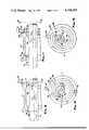
- FIG. 1is a somewhat diagrammatic, partial longitudinal cross section of a machine tool having a boring spindle embodying the present invention
- FIG. 2is a diagram of the machine cycle
- FIG. 3is a sectional view along the line 3--3 in FIG. 1;
- FIG. 4is an enlarged fragmentary view of a portion of the arrangement shown in FIG. 1;
- FIG. 5is a sectional view along the line 5--5 in FIG. 4;
- FIG. 6is a fragmentary sectional view illustrating the manner in which the boring bar is rotated about its axis to adjust the positions of the cutting tools thereon in a radial direction;
- FIGS. 7 and 8are fragmentary sectional views showing the manner in which two of the cutting tools operate.
- FIGS. 9, 10, 11 and 12show the progression of the cutting tools during a cutting cycle, FIGS. 10 and 12 being taken along the lines 10--10 and 12--12 of FIGS. 9 and 11 respectively.
- FIG. 1there is illustrated one form of machine tool embodying the present invention.
- the machineincludes a spindle housing 10 mounted on a slide 12 which is in turn mounted for rectilinear sliding movement on a base 14.
- Spindle 18rotates about an axis A-1.
- flange nut 22is permitted to rotate within, but prevented from moving axially of, spindle 18.
- a boring bar 26which carries two single point cutting tools 29 and 31.
- Tools 29, 31are mounted on boring bar 26 in generally diametrically opposed relation.
- Boring bar 26is mounted on nut 22 concentric with the bore 21, the axis of rotation of nut 22 and boring bar 26 being designated A-2.
- axis A-2is radially offset from the axis A-1 of the spindle 18 a selected distance as shown more clearly in FIG. 3.
- the axially inner end of nut 22is formed with helical splines 30 that are engaged with mating helical splines 28 formed on the radially off-set portion of a shaft 34.
- the axis of the helically splined portion 28coincides with axis A-2 and the straight splined portion 35 of shaft 34 has its axis coinciding with axis A-1.
- Spline portion 35engages a similarly straight splined insert 32 which is fixedly mounted at the inner end of spindle 18 concentric with the axis A-1. Insert 32 prevents relative torsional shift between spindle 18 and shaft 34 while permitting relative axial movement therebetween.
- the helix angle of the spline set 28,30is approximately 30°. Any axial movement of shaft 34 will cause an angular displacement of nut 22, and, consequently, of tools 29,31.
- Shaft 34is rotationally coupled to a cylindrical slide 38 by thrust bearings 36 which are so secured as to withstand the thrust forces imposed by a fluid cylinder 40 through the T slot coupling 42.
- Slide 38is mounted for reciprocation in a block 43 fixed on slide 12.
- the stroke of shaft 34is determined by a pair of wedges 44,46 arranged within slots 48,50, respectively, in cylindrical slide 38.
- Wedges 44,46are adjustable in a direction perpendicular to the longitudinal axis of slide 38. Adjustment of these wedges, therefore, controls the position of slide 38 at each end of its stroke.
- the position of slide 38 at each end of its strokein turn determines the radial position of the cutting tools 29,31 relative to the axis A-1, that is, the axis about which they are rotating with spindle 18.
- the present inventionis directed primarily to the provision of additional cutting tools on the spindle which are automatically sequenced in the course of a single cycle of the machine.
- One of these additional toolsis designated 52 and is mounted on a block 54 carried by a slide 56.
- Slide 56is mounted on the flanged end 58 of spindle 18 and is retained and guided for rectilinear movement thereon by gibs 60.
- the flanged end of nut 22is formed as a cylindrical eccentric 62, the central axis of which is designated A-3.
- Eccentric 62is in the form of a circular hub seated within the cylindrical opening of a follower block 64 that is guided for rectilinear movement in slot 66 formed in slide 56. As shown in FIG.
- the radial distance between axes A-1 and A-3is approximately at least twice the radial distance between the axes A-1 and A-2.
- the high point 68 of eccentric 62 and tool 29preferably lie in the same radial plane which passes through axes A-2 and A-3 as shown in FIG. 3.
- a fourth single edge cutting tool 70is fixedly mounted on a tool block 72.
- Tool block 72is in turn fixedly attached to flange 58 of spindle 18 in a position preferably diametrically opposite tool block 54.
- the tips of tools 52,70lie in the same radial plane.
- the workpiece to be machined by the tools describedcomprises a casting W adapted to be fixedly located relative to base 14 by means of a pallet, chuck or other work-holding device designated C.
- tool 29is arranged to machine bore 74 and shoulder 76; tool 31 is arranged to machine bore 78 and shoulder 80; tool 52 is arranged to machine face 82; and tool 70 is arranged to machine the cylindrical surface 84.
- FIG. 2One complete machining cycle of the machine is illustrated diagrammatically in FIG. 2.
- slide 12In the starting position slide 12 is in a fully retracted position and slide 38 is in the full forward position wherein the rear face of slot 48 abuts wedge 44.
- nut 22has been rotated relative to spindle 18 to shift tool 29 to its radially outermost position.
- Tool 29lies on the radial line designated L-1 in FIG. 3. This position is determined by the interengagement of wedge 44 with the rear end face of slot 48.
- the cutting cyleis initiated by advancing slide 12 forwardly first at a rapid rate and then at a feed rate as the cutting tool 29 approaches the workpiece.
- Slide 12is powered by a cylinder 85.
- tool 29is located radially relative to the axis A-1 to machine the bore 74 to the desired diameter.
- tool 70machines the cylindrical surface 84 to the proper diameter (FIG. 8) while tool 29 finishes bore 74.
- tool 52is located axially in its proper position to machine face 82 and tool 31 is positioned axially outward beyond the opposite end of the workpiece.
- the axial depth of bore 74is determined by an adjustable stop 86 on base 14 which is engaged by slide 12 to limit the forward movement thereof. This is the position of the mechanism as shown in FIG. 1.
- cylinder 40is actuated by a switch (not shown) to retract slide 38 to a position wherein wedge 46 abuts beyond the forward end of slot 50. This is designated as the second feed in FIG. 2.
- a switchnot shown
- nut 22is rotated somewhat less than 180° relative to the spindle 18.
- nut 22is rotated so that tool 29 is shifted circumferentially relative to the spindle from the position designated L-1 to the position designated L-2.
- tool 31which is preferably located on boring bar 26 diametrically opposite tool 29, is shifted circumferentially from the position designated L-3 to the position designated L-4.
- tool 29is being shifted radially inwardly to machine shoulder 76.
- the initial position of tool 29is shown in FIGS. 4 and 5 and the manner in which it is radially retracted relative to the axis A-1 is illustrated in FIGS. 6 and 10.
- the axes A-1, A-2 and A-3are so located relative to one another such that tool 52 does not engage face 82 until tool 29 has been retracted radially inwardly to finish machining shoulder 76. This is illustrated in FIGS. 9 and 10 and insures that any disturbance of the workpiece by the action of tool 29 will not affect the cutting action of the other tool 52.
- the radially innermost position of tool 52is shown in FIG. 7.
- a suitable switchagain actuates cylinder 40 to retract slide 38 to its starting position relative to slide 12 so that tool 31 will be shifted radially inwardly to machine shoulder 80 and tool 29 will be shifted radially outwardly to its proper position for machining bore 74 on the next workpiece.
- the diameters of bores 74 and 78are critical and the precise location of wedges 44,46 to limit the stroke of slide 38 at its opposite ends must be very precise.
- the radially inwardmost position of tool 52may vary slightly when tool 31 is size-compensated by the adjustment of wedge 46, face 82 and cylindrical surface 84 simply form a locating pilot portion on the workpiece, and, if the junction of these surfaces are slightly beveled or undercut, this does not present any objection since the bore on the end of the mating workpiece may be chamfered.
Landscapes
- Engineering & Computer Science (AREA)
- Mechanical Engineering (AREA)
- Cutting Tools, Boring Holders, And Turrets (AREA)
- Drilling And Boring (AREA)
Abstract
Description
This invention relates to a machine tool boring spindle, and, more particularly, to an adjusting means on a boring tool spindle for automatically displacing a plurality of tools radially for successively machining a plurality of annular surfaces on a workpiece during a single work cycle of the spindle.
Many workpieces have to be machined with a plurality of co-axial bores or cylindrical surfaces, each terminating in a shoulder at one end. This is true, for example, of castings designed to receive bearings and seals for supporting or enclosing one or more coaxial shaft members. The bearings and seals are seated on cylindrical surfaces and bear against machined shoulders at the ends of such surfaces. In many such castings it is extremely important that the bores or cylindrical surfaces are coaxial to a high degree of accuracy and that the shoulders are perpendicular to the axis of the bores to a high degreee of accuracy. As is disclosed in U.S. Pat. No. 3,884,590, this can be readily accomplished by mounting a pair of cutting tools on a single boring bar so that two bores can be successively machined in a single continuous operation of the machine. However, in the arrangement shown in said patent the number of bores that can be machined in one cycle of the machine is limited to two. Additional bores or cylindrical surfaces require machining as a separate operation. The present invention is an improvement over the arrangement shown in said patent.
The primary object of the present invention is to enable machining of at least three coaxial bores or cylindrical surfaces with square shoulders to a high degree of accuracy in a single continuous operation.
A further and more specific object of this invention is to provide a boring machine wherein two tool holders, one of which has at least two cutting tools thereon, are mounted on a single boring machine spindle and a single mechanism is provided for radially displacing both tool holders simultaneously so that at least three bores or cylindrical surfaces can be machined on a workpiece in a single continuous cycle of the machine.
Other objects, features and advantages of the present invention will become apparent from the following description and accompanying drawings, in which:
FIG. 1 is a somewhat diagrammatic, partial longitudinal cross section of a machine tool having a boring spindle embodying the present invention;
FIG. 2 is a diagram of the machine cycle;
FIG. 3 is a sectional view along theline 3--3 in FIG. 1;
FIG. 4 is an enlarged fragmentary view of a portion of the arrangement shown in FIG. 1;
FIG. 5 is a sectional view along the line 5--5 in FIG. 4;
FIG. 6 is a fragmentary sectional view illustrating the manner in which the boring bar is rotated about its axis to adjust the positions of the cutting tools thereon in a radial direction;
FIGS. 7 and 8 are fragmentary sectional views showing the manner in which two of the cutting tools operate; and
FIGS. 9, 10, 11 and 12 show the progression of the cutting tools during a cutting cycle, FIGS. 10 and 12 being taken along thelines 10--10 and 12--12 of FIGS. 9 and 11 respectively.
In FIG. 1 there is illustrated one form of machine tool embodying the present invention. The machine includes aspindle housing 10 mounted on aslide 12 which is in turn mounted for rectilinear sliding movement on abase 14. Journalled withinhousing 10, as bybearings 16, is ahollow spindle 18 rotationally driven by a belt andpulley 20 from a motor (not illustrated).Spindle 18 rotates about an axis A-1. Mounted within thebore 21 of aspindle 18 there is journalled a flange nut 22 which is prevented from shifting axially relative tospindle 18 by a retainer and bearing member 24. Thus, flange nut 22 is permitted to rotate within, but prevented from moving axially of,spindle 18. On the other end of nut 22 there is securely mounted, as byscrews 25, aboring bar 26 which carries two singlepoint cutting tools Tools boring bar 26 in generally diametrically opposed relation.Boring bar 26 is mounted on nut 22 concentric with thebore 21, the axis of rotation of nut 22 andboring bar 26 being designated A-2. It will be observed that axis A-2 is radially offset from the axis A-1 of the spindle 18 a selected distance as shown more clearly in FIG. 3. The axially inner end of nut 22 is formed with helical splines 30 that are engaged with matinghelical splines 28 formed on the radially off-set portion of ashaft 34. The axis of the helically splinedportion 28 coincides with axis A-2 and the straightsplined portion 35 ofshaft 34 has its axis coinciding with axis A-1.
The present invention is directed primarily to the provision of additional cutting tools on the spindle which are automatically sequenced in the course of a single cycle of the machine. One of these additional tools is designated 52 and is mounted on ablock 54 carried by aslide 56.Slide 56 is mounted on theflanged end 58 ofspindle 18 and is retained and guided for rectilinear movement thereon bygibs 60. The flanged end of nut 22 is formed as a cylindrical eccentric 62, the central axis of which is designated A-3. Eccentric 62 is in the form of a circular hub seated within the cylindrical opening of a follower block 64 that is guided for rectilinear movement inslot 66 formed inslide 56. As shown in FIG. 3, the radial distance between axes A-1 and A-3 is approximately at least twice the radial distance between the axes A-1 and A-2. Thehigh point 68 of eccentric 62 andtool 29 preferably lie in the same radial plane which passes through axes A-2 and A-3 as shown in FIG. 3. With the above described arrangement it will be appreciated that when nut 22 is rotated relative tospindle 18tool 52, as is the case oftools
A fourth singleedge cutting tool 70 is fixedly mounted on atool block 72.Tool block 72 is in turn fixedly attached toflange 58 ofspindle 18 in a position preferably diametricallyopposite tool block 54. The tips oftools
The workpiece to be machined by the tools described comprises a casting W adapted to be fixedly located relative tobase 14 by means of a pallet, chuck or other work-holding device designated C. Referring to FIG. 4, in the tool arrangement describedtool 29 is arranged to machinebore 74 andshoulder 76;tool 31 is arranged to machinebore 78 andshoulder 80;tool 52 is arranged to machineface 82; andtool 70 is arranged to machine thecylindrical surface 84.
One complete machining cycle of the machine is illustrated diagrammatically in FIG. 2. In thestarting position slide 12 is in a fully retracted position andslide 38 is in the full forward position wherein the rear face of slot 48abuts wedge 44. Thus, nut 22 has been rotated relative tospindle 18 to shifttool 29 to its radially outermost position.Tool 29 lies on the radial line designated L-1 in FIG. 3. This position is determined by the interengagement ofwedge 44 with the rear end face of slot 48. The cutting cyle is initiated by advancingslide 12 forwardly first at a rapid rate and then at a feed rate as the cuttingtool 29 approaches the workpiece.Slide 12 is powered by acylinder 85. In theaforesaid position tool 29 is located radially relative to the axis A-1 to machine thebore 74 to the desired diameter. As the slide approaches the end of its forward stroke,tool 70 machines thecylindrical surface 84 to the proper diameter (FIG. 8) whiletool 29 finishes bore 74. At thistime tool 52 is located axially in its proper position tomachine face 82 andtool 31 is positioned axially outward beyond the opposite end of the workpiece. The axial depth ofbore 74 is determined by anadjustable stop 86 onbase 14 which is engaged byslide 12 to limit the forward movement thereof. This is the position of the mechanism as shown in FIG. 1.
Afterslide 12 engagesstop 86,cylinder 40 is actuated by a switch (not shown) to retractslide 38 to a position whereinwedge 46 abuts beyond the forward end of slot 50. This is designated as the second feed in FIG. 2. As theshaft 34 is retracted nut 22 is rotated somewhat less than 180° relative to thespindle 18. Referring to FIG. 3, nut 22 is rotated so thattool 29 is shifted circumferentially relative to the spindle from the position designated L-1 to the position designated L-2. At the same time,tool 31, which is preferably located on boringbar 26 diametricallyopposite tool 29, is shifted circumferentially from the position designated L-3 to the position designated L-4. As theboring bar 26 is being rotated relative to spindle 18, the latter being driven by the pulley andbelt 20,tool 29 is being shifted radially inwardly tomachine shoulder 76. The initial position oftool 29 is shown in FIGS. 4 and 5 and the manner in which it is radially retracted relative to the axis A-1 is illustrated in FIGS. 6 and 10. The axes A-1, A-2 and A-3 are so located relative to one another such thattool 52 does not engageface 82 untiltool 29 has been retracted radially inwardly to finish machiningshoulder 76. This is illustrated in FIGS. 9 and 10 and insures that any disturbance of the workpiece by the action oftool 29 will not affect the cutting action of theother tool 52. The radially innermost position oftool 52 is shown in FIG. 7.
Whenslide 38 is in the fully retracted position,tool 52 has been advanced radially inwardly to the position shown in FIGS. 11 and 12 wherein theface 82 is fully machined andtool 31 has been shifted radially outwardly to machine bore 78 to the desired diameter whenslide 12 is thereafter retracted during the portion of the cycle designated "third feed" in FIG. 2. The position ofslide 12 at the end of the cycle portion designated "third feed" is determined by aretractable stop 88. When the slide engages stop 88tool 31 has been advanced axially to the right from the position shown in FIG. 11 so as to be properly positioned tomachine shoulder 80. At this point a suitable switch (not illustrated) again actuatescylinder 40 to retractslide 38 to its starting position relative to slide 12 so thattool 31 will be shifted radially inwardly tomachine shoulder 80 andtool 29 will be shifted radially outwardly to its proper position for machining bore 74 on the next workpiece.
In the workpiece illustrated the diameters ofbores wedges slide 38 at its opposite ends must be very precise. Although the radially inwardmost position oftool 52 may vary slightly whentool 31 is size-compensated by the adjustment ofwedge 46, face 82 andcylindrical surface 84 simply form a locating pilot portion on the workpiece, and, if the junction of these surfaces are slightly beveled or undercut, this does not present any objection since the bore on the end of the mating workpiece may be chamfered.
Claims (15)
1. In a machine tool the combination comprising a housing, a spindle journalled in said housing for rotation about a first axis, drive means for rotating said spindle, means for supporting a workpiece in axial alignment with said first axis, means for moving the spindle and workpiece support axially relative to one another, an annular member fixed axially on said spindle for rotation therewith, said annular member also being rotatable relative to said spindle about a second axis parallel to and spaced from said first axis, a first tool holder fixedly mounted on said annular member for rotation therewith, a cutting tool mounted on said first tool holder such that, when the annular member is rotated relative to said spindle, said cutting tool is shifted radially toward and away from said first axis, a second tool holder mounted on said spindle for rotation therewith and for radial movement thereon, a cutting tool mounted on the second tool holder and having a cutting point thereon, means connecting the second tool holder and the annular member such that the second tool holder and the cutting tool thereon are displaced radially on said spindle toward and away from said first axis in response to rotation of the annular member relative to the spindle, and means for incrementally rotating the annular member about said second axis relative to said spindle while the spindle is rotatably driven about said first axis to simultaneously displace both the first and second mentioned tools radially relative to said first axis.
2. The combination set forth in claim 1 wherein the means connecting the second tool holder and said annular member comprises a circular hub on said annular member having a central axis which is parallel to and spaced radially from said first and second axes, follower means on the second tool holder having a circular socket rotatably engaging the circular hub on said annular member for displacing the second tool holder radially on said spindle relative to said first axis in response to relative rotation between the annular member and said spindle.
3. The combination set forth in claim 2 wherein said second tool holder comprises a slide on said spindle guided for rectilinear radial movement thereon.
4. The combination set forth in claim 2 wherein said spindle has a radially extending guideway thereon, said second tool holder being mounted in said guideway for rectilinear movement.
5. The combination set forth in claim has a wherein the second tool holder has rectilinear guideway thereon perpendicular to the rectilinear guideway on the spindle, said follower means being guided for rectilinear movement in said second-mentioned guideway.
6. The combination set forth in claim 5 wherein said first tool holder has a second cutting tool mounted thereon which is spaced axially from and generally diametrically opposite the first mentioned cutting tool so that when said annular member is rotated relative to said spindle one of the cutting tools on the first tool holder is shifted radially toward said first axis while the other is shifted radially away from said first axis.
7. The combination set forth in claim 1 wherein said means connecting the second tool holder and said annular member comprises a first radial guideway on said spindle, said tool holder being mounted in said guideway for movement radially on said spindle, a second radial guideway on said tool holder extending perpendicular to said first guideway, a guide block slideably mounted in the second guideway and a cylindrical boss on said annular member having a central axis parallel to and spaced from said first and second axes, said guide block having a circular opening therein engaging said cylindrical boss.
8. The combination set forth in claim 1 including a third tool holder fixedly mounted on said spindle, a cutting tool fixedly mounted on said third tool holder and having a cutting tip lying in substantially the same radial plane as the cutting tip of the second mentioned cutting tool.
9. The combination set forth in claim 8 wherein said third cutting tool is positioned to machine a cylindrical surface on the workpiece when the workpiece and spindle are moved relatively axially and the cutting tool on the second tool holder is positioned to machine a radial shoulder on the workpiece intersecting and perpendicular to said cylindrical surface when the annular member is rotated relative to the rotating spindle.
10. The combination set forth in claim 1 wherein the first and second mentioned cutting tools are located relative to each other such that when the annular member is rotated in one direction relative to the rotating spindle the first and second mentioned cutting tools are both displaced radially inwardly to machine two discrete annular shoulder portions on the workpiece.
11. The combination set forth in claim 10 wherein said second and third axes are spaced radially from said first axis such that when the annular member is rotated in one direction relative to the rotating spindle one of the last-two-mentioned tools is displaced radially out of cutting engagement with the workpiece before the other is displaced radially into cutting engagement with the workpiece.
12. The combination set forth in claim 11 wherein the cutting tool on the second tool holder is spaced radially outwardly from the cutting tool on the first tool holder.
13. The combination set forth in claim 11 wherein said third axis is spaced radially from said first axis a greater distance than the spacing between said first axis and said second axis.
14. The combination set forth in claim 13 wherein the cutting tool on the first tool holder lies generally in a plane passing through said second and third axes.
15. The combination set forth in claim 14 wherein the second axis is located radially intermediate the first and third axes.
Priority Applications (2)
| Application Number | Priority Date | Filing Date | Title |
|---|---|---|---|
| US05/892,660US4154555A (en) | 1978-04-03 | 1978-04-03 | Multiple boring head |
| CA321,008ACA1091479A (en) | 1978-04-03 | 1979-02-07 | Multiple boring head |
Applications Claiming Priority (1)
| Application Number | Priority Date | Filing Date | Title |
|---|---|---|---|
| US05/892,660US4154555A (en) | 1978-04-03 | 1978-04-03 | Multiple boring head |
Publications (1)
| Publication Number | Publication Date |
|---|---|
| US4154555Atrue US4154555A (en) | 1979-05-15 |
Family
ID=25400315
Family Applications (1)
| Application Number | Title | Priority Date | Filing Date |
|---|---|---|---|
| US05/892,660Expired - LifetimeUS4154555A (en) | 1978-04-03 | 1978-04-03 | Multiple boring head |
Country Status (2)
| Country | Link |
|---|---|
| US (1) | US4154555A (en) |
| CA (1) | CA1091479A (en) |
Cited By (15)
| Publication number | Priority date | Publication date | Assignee | Title |
|---|---|---|---|---|
| US4345860A (en)* | 1980-07-14 | 1982-08-24 | Alex Shashaty | Boring machine and method of rigidizing a boring bar |
| US4463487A (en)* | 1981-04-30 | 1984-08-07 | Associated Engineering Italy S.P.A. | Method of manufacturing piston rings |
| EP0164582A1 (en)* | 1984-05-12 | 1985-12-18 | Manfred König | Mounting device for centred mounting of rotating parts |
| US4602539A (en)* | 1983-02-07 | 1986-07-29 | Kabushiki Kaisha Komatsu Seisakusho | Spindle mechanism providing for a continuous change in cutting radius, and method of operation |
| US4692074A (en)* | 1986-04-11 | 1987-09-08 | The Cross Company | Tool coupling arrangement for a tooling assembly |
| US4773799A (en)* | 1986-06-03 | 1988-09-27 | Framatome | Apparatus for sampling a section of tube in a nuclear fuel assembly |
| US5030042A (en)* | 1989-07-04 | 1991-07-09 | Fuji Seiko Limited | Machining apparatus having means for changing radial position of cutting tools |
| US5061125A (en)* | 1989-08-23 | 1991-10-29 | Cross Europa-Werk, Gmbh | Boring device |
| US5163789A (en)* | 1990-03-09 | 1992-11-17 | Fischerwerke Artur Fischer Gmbh & Co. Kg | Device for producing drilled holes with an undercut |
| US5735029A (en)* | 1996-12-12 | 1998-04-07 | Western Atlas, Inc. | Flexible arbor mill machine |
| US6755598B2 (en) | 2001-09-20 | 2004-06-29 | Siemens Energy & Automation, Inc. | Multi-tool boring head and process for boring |
| US20090193932A1 (en)* | 2005-09-02 | 2009-08-06 | Mapal Fabrik Fur Prazisionswerkzeuge Dr. Kress Kg | Tool for Machining Workpiece Surfaces |
| CN102756180A (en)* | 2012-07-06 | 2012-10-31 | 沪东中华造船(集团)有限公司 | Machining device and machining method of bolt mounting part of lower plane of ship equipment base |
| US20180369920A1 (en)* | 2015-11-17 | 2018-12-27 | Citizen Watch Co., Ltd. | Machine tool and method for processing by machine tool |
| CN114850519A (en)* | 2022-04-14 | 2022-08-05 | 哈尔滨理工大学 | A Synchronous Variable Diameter Modular Indexable CNC Boring System |
Citations (3)
| Publication number | Priority date | Publication date | Assignee | Title |
|---|---|---|---|---|
| US3884590A (en)* | 1974-05-22 | 1975-05-20 | Lamb Co F Jos | Adjustable dual tool boring bar |
| US3902386A (en)* | 1973-07-25 | 1975-09-02 | Renault | Arrangement for control of a boring tool and a machining tool in a direction distinct from the axial direction |
| US4004332A (en)* | 1975-12-18 | 1977-01-25 | Wawrzyniak Walter W | Facing head |
- 1978
- 1978-04-03USUS05/892,660patent/US4154555A/ennot_activeExpired - Lifetime
- 1979
- 1979-02-07CACA321,008Apatent/CA1091479A/ennot_activeExpired
Patent Citations (3)
| Publication number | Priority date | Publication date | Assignee | Title |
|---|---|---|---|---|
| US3902386A (en)* | 1973-07-25 | 1975-09-02 | Renault | Arrangement for control of a boring tool and a machining tool in a direction distinct from the axial direction |
| US3884590A (en)* | 1974-05-22 | 1975-05-20 | Lamb Co F Jos | Adjustable dual tool boring bar |
| US4004332A (en)* | 1975-12-18 | 1977-01-25 | Wawrzyniak Walter W | Facing head |
Cited By (17)
| Publication number | Priority date | Publication date | Assignee | Title |
|---|---|---|---|---|
| US4345860A (en)* | 1980-07-14 | 1982-08-24 | Alex Shashaty | Boring machine and method of rigidizing a boring bar |
| US4463487A (en)* | 1981-04-30 | 1984-08-07 | Associated Engineering Italy S.P.A. | Method of manufacturing piston rings |
| US4602539A (en)* | 1983-02-07 | 1986-07-29 | Kabushiki Kaisha Komatsu Seisakusho | Spindle mechanism providing for a continuous change in cutting radius, and method of operation |
| EP0164582A1 (en)* | 1984-05-12 | 1985-12-18 | Manfred König | Mounting device for centred mounting of rotating parts |
| US4692074A (en)* | 1986-04-11 | 1987-09-08 | The Cross Company | Tool coupling arrangement for a tooling assembly |
| US4773799A (en)* | 1986-06-03 | 1988-09-27 | Framatome | Apparatus for sampling a section of tube in a nuclear fuel assembly |
| US5030042A (en)* | 1989-07-04 | 1991-07-09 | Fuji Seiko Limited | Machining apparatus having means for changing radial position of cutting tools |
| US5061125A (en)* | 1989-08-23 | 1991-10-29 | Cross Europa-Werk, Gmbh | Boring device |
| US5163789A (en)* | 1990-03-09 | 1992-11-17 | Fischerwerke Artur Fischer Gmbh & Co. Kg | Device for producing drilled holes with an undercut |
| US5735029A (en)* | 1996-12-12 | 1998-04-07 | Western Atlas, Inc. | Flexible arbor mill machine |
| US6755598B2 (en) | 2001-09-20 | 2004-06-29 | Siemens Energy & Automation, Inc. | Multi-tool boring head and process for boring |
| US20090193932A1 (en)* | 2005-09-02 | 2009-08-06 | Mapal Fabrik Fur Prazisionswerkzeuge Dr. Kress Kg | Tool for Machining Workpiece Surfaces |
| US8555757B2 (en)* | 2005-09-02 | 2013-10-15 | Mapal Fabrik Fur Prazisionswerkzeuge Dr. Kress Kg | Tool for machining workpiece surfaces |
| CN102756180A (en)* | 2012-07-06 | 2012-10-31 | 沪东中华造船(集团)有限公司 | Machining device and machining method of bolt mounting part of lower plane of ship equipment base |
| US20180369920A1 (en)* | 2015-11-17 | 2018-12-27 | Citizen Watch Co., Ltd. | Machine tool and method for processing by machine tool |
| US10661349B2 (en)* | 2015-11-17 | 2020-05-26 | Citizen Watch Co., Ltd. | Machine tool and method for processing by machine tool |
| CN114850519A (en)* | 2022-04-14 | 2022-08-05 | 哈尔滨理工大学 | A Synchronous Variable Diameter Modular Indexable CNC Boring System |
Also Published As
| Publication number | Publication date |
|---|---|
| CA1091479A (en) | 1980-12-16 |
Similar Documents
| Publication | Publication Date | Title |
|---|---|---|
| US4154555A (en) | Multiple boring head | |
| US3884590A (en) | Adjustable dual tool boring bar | |
| US4250775A (en) | Machine tool and method | |
| US4934040A (en) | Spindle driver for machine tools | |
| EP0067204B1 (en) | Rotary cutting tool holder | |
| EP0467372B1 (en) | Valve seat bushing machining apparatus | |
| US3795957A (en) | Apparatus for boring and burnishing internal cylindrical surfaces of metallic workpieces | |
| USRE32211E (en) | Machine tool and method | |
| US5086676A (en) | Method and apparatus for machining a differential carrier | |
| US4589310A (en) | Chuck and rotary tool to be used when making a hole in a workpiece | |
| US4606683A (en) | Method and device for producing thread | |
| US4813828A (en) | Bottle boring milling tool | |
| US2383050A (en) | Multiple operation toolhead | |
| US5030042A (en) | Machining apparatus having means for changing radial position of cutting tools | |
| US4627773A (en) | Right angle spindle for machine tools | |
| US3724303A (en) | Chamfering apparatus for tubular articles | |
| US2338687A (en) | Machine for scalping bars | |
| JPH01109015A (en) | Bottle boring milling tool | |
| US5035551A (en) | Method, chuck and rotary tool to be used when making a hole in a workpiece | |
| US3438288A (en) | Bearing support for tool spindles | |
| US3530744A (en) | Machine tool | |
| US4528876A (en) | Universal single spindle pin crankshaft lathe | |
| US2867139A (en) | Boring unit | |
| US3477319A (en) | Recessing tool | |
| US3129620A (en) | Floating tool for removing burrs from machined surfaces |
Legal Events
| Date | Code | Title | Description |
|---|---|---|---|
| AS | Assignment | Owner name:LAMB TECHNICON CORP. Free format text:CHANGE OF NAME;ASSIGNOR:F. JOS. LAMB COMPANY;REEL/FRAME:004165/0313 Effective date:19801217 | |
| AS | Assignment | Owner name:WESTERN ATLAS INC., KENTUCKY Free format text:CHANGE OF NAME;ASSIGNOR:LAMB TECHNICON CORPORATION;REEL/FRAME:007541/0759 Effective date:19931007 | |
| AS | Assignment | Owner name:MAGUS GMBH, SWITZERLAND Free format text:ASSIGNMENT OF ASSIGNORS INTEREST;ASSIGNOR:UNOVA IP CORP.;REEL/FRAME:015980/0302 Effective date:20050422 | |
| AS | Assignment | Owner name:MAGUS INTELLECTUAL PROPERTY GMBH, SWITZERLAND Free format text:CORRECTIVE ASSIGNMENT TO CORRECT THE NAME OF THE ASSIGNEE TO MAGUS INTELLECTUAL PROPERTY GMBH PREVIOUSLY RECORDED ON REEL 015980 FRAME 0302;ASSIGNOR:UNOVA IP CORP.;REEL/FRAME:017223/0824 Effective date:20050422 |