US4150851A - Seat for bicycles and the like - Google Patents
Seat for bicycles and the likeDownload PDFInfo
- Publication number
- US4150851A US4150851AUS05/831,257US83125777AUS4150851AUS 4150851 AUS4150851 AUS 4150851AUS 83125777 AUS83125777 AUS 83125777AUS 4150851 AUS4150851 AUS 4150851A
- Authority
- US
- United States
- Prior art keywords
- seat post
- frame
- locking pin
- frame seat
- hole
- Prior art date
- Legal status (The legal status is an assumption and is not a legal conclusion. Google has not performed a legal analysis and makes no representation as to the accuracy of the status listed.)
- Expired - Lifetime
Links
Images
Classifications
- B—PERFORMING OPERATIONS; TRANSPORTING
- B62—LAND VEHICLES FOR TRAVELLING OTHERWISE THAN ON RAILS
- B62K—CYCLES; CYCLE FRAMES; CYCLE STEERING DEVICES; RIDER-OPERATED TERMINAL CONTROLS SPECIALLY ADAPTED FOR CYCLES; CYCLE AXLE SUSPENSIONS; CYCLE SIDE-CARS, FORECARS, OR THE LIKE
- B62K19/00—Cycle frames
- B62K19/30—Frame parts shaped to receive other cycle parts or accessories
- B62K19/36—Frame parts shaped to receive other cycle parts or accessories for attaching saddle pillars, e.g. adjustable during ride
- Y—GENERAL TAGGING OF NEW TECHNOLOGICAL DEVELOPMENTS; GENERAL TAGGING OF CROSS-SECTIONAL TECHNOLOGIES SPANNING OVER SEVERAL SECTIONS OF THE IPC; TECHNICAL SUBJECTS COVERED BY FORMER USPC CROSS-REFERENCE ART COLLECTIONS [XRACs] AND DIGESTS
- Y10—TECHNICAL SUBJECTS COVERED BY FORMER USPC
- Y10T—TECHNICAL SUBJECTS COVERED BY FORMER US CLASSIFICATION
- Y10T403/00—Joints and connections
- Y10T403/32—Articulated members
- Y10T403/32254—Lockable at fixed position
- Y10T403/32467—Telescoping members
- Y10T403/32516—Remotely actuated
Definitions
- Ths inventionrelates to a seat, and, more particularly, to an adjustable seat for bicycles, motorcycles, and stationary pedal actuated cycle-type exercise machines.
- the present adjustable seatfits the above-described design criteria because the number of parts required to make the seat adjustable have been reduced, and the parts that are required are to a large extent off-the-shelf items requiring little modification to make them suitable for their purpose.
- a hollow seat posthas a seat at one end while the opposite end is split to define an aligning pin receiving groove. One portion of the split opposite end has longitudinally spaced pin receiving holes.
- the hollow seat postis insertable inside a hollow frame seat post and the seat post is just large enough for an easy sliding fit inside the frame seat post.
- a coil springis inserted the frame seat post below the seat post.
- a first pinextends through the bottom of the frame seat post and serves as a stop for the spring.
- a second pin extending through the upper end of the frame seat postaligns the seat with respect to the frame when the seat post is inserted inside the frame seat post with the second pin in the pin receiving groove.
- a lever actuated spring biased locking pin mounted on the frame in the pinis aligned with a hole extending through the frame seat post and is movable therein.
- One of the objects of this inventionis to provide a simple economical-to-make adjustable seat for use on bicycles, motorcycles, exercycles, and the like.
- a further object of this inventionis to provide a seat which can be adjusted with respect to height while the machine is being used.
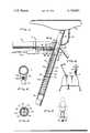
- FIG. 1is an elevational view partly in section showing the adjustable seat mounted on a cycle frame.
- FIG. 2is a sectional view taken on the line 2--2 of FIG. 1.
- FIG. 3is a sectional view taken on the line 3--3 of FIG. 1.
- FIG. 4is an elevational view showing the adjustable seat mounted on an exercycle.
- FIG. 5is an elevational view showing the adjustable seat mounted on a motorcycle.
- the frame of a bicycle indicated generally by the reference number 10includes a horizontal support bar 12 and a generally vertical hollow frame seat post 14.
- a seat post 16has a seat 18 attached at one end.
- the opposite end 20 of the seat post 16is split defining an aligning pin receiving groove 22 between tines 23 and 25.
- a first coil spring 24is inserted inside the frame seat post 14 for reasons to be described below.
- a stopmay or may not be required against which one end of the coil spring may rest. If the bottom of the seat post is shaped so it cannot serve as a stop, a simple pin 26 is inserted diametrically through the bottom of the frame seat post for supporting the lower end of the coil spring 24.
- the coil spring 24is compressed between the lower end 28 of the seat post 16 and the pin 26.
- the frame seat post 14is provided with a hole 32 extending therethrough. See FIG. 3.
- a simple pin 34extends through the hole and is locked to the frame seat post 14 by any suitable means.
- the diameter of the pin 34is slightly less than the width of the groove 22 in the seat post 16, and the pin 34 and the groove 22 are so disposed with respect to each other that when the seat post 16 is inserted inside the frame seat post 14, with the pin 34 in groove 22, the seat 18 will be aligned correctly with respect to the frame 10.
- Tine 23 of the seat post 16is provided with longitudinally spaced height adjusting holes 30.
- the frame seat post 14is provided with a locking pin receiving hole 36, which is the same size as hole 30.
- a spring actuated locking pin 38is mounted on the frame for penetrating holes 30 and 36.
- the horizontal frame member 12is, in this particular embodiment, provided with downwardly extending support member 40 and a combined support and guide member 42.
- Members 40 and 42have aligned openings extending therethrough through which the pin 38 extends. These aligned openings maintain pin 38 in spaced parallel relationship to frame member 12.
- Support member 42is provided with an integrally attached aligning tube 44 which is attached to frame seat post 14 over opening 36.
- Pin 38is long enough to extend through the support members 40 and 42 and through the aligning tube 44 and so it can penetrate holes 36 and 30. In this way, pin 38 will always be in alignment with hole 36.
- a stop member 46is secured to pin 38, and a second coil spring 48 is mounted over pin 38 between stop member 46 and support 40. The effect of spring 48 is to bias pin 38 in a direction through the aligning tube 44 and through holes 36 and 30.
- One end of a cablewhich may be the same type of cable used on bicycle brakes, is secured by any suitable means to the end 52 of pin 38.
- An operating handle 54 like that used on bicycle brakesis secured by any suitable means to frame 10.
- the opposite end of cable 50is secured to the operating handle in such a way that when the operating handle 54 is squeezed against the frame member 12, the cable 50 pulls pin 38 against the bias of the coil spring and moves the pin 38 out of holes 30 and 36.
- the coil spring 48again biases the pin 38 towards hole 36.
- a chain 56is secured between seat 18 and frame seat post 14 to prevent this seat from flying violently away from the frame in the event the operating handle 54 is inadvertently squeezed while no one is on the seat.
- FIG. 4shows the teachings of this device used in connection with a pedal actuated stationary exercising cycle of the type commonly used in gymnasiums and which are known as exercycles.
- the exercycle in a gymnasiumis used by large numbers of different people during the course of the day, and the adjustable seat provides a simple way to conveniently vary the seat height in accordance with the requirements of the various users.
- the lever member 54is mounted on the vertically disposed frame seat post 14.
- the locking pin 38 and coil spring 48(not shown) are mounted in a support member and aligning tube which is secured by any suitable means to the frame seat post 14.
- a cable like that shown in FIG. 1is connected at one end of the locking pin and at the other end to lever member 54. When the lever member 54 is pressed against the frame seat post, the cable pulls the locking pin against the biasing force exerted by coil spring 48 out of the hole in the frame seat post to permit the height of the seat 18 to be adjusted.
- FIG. 5shows the adjustable seat used in connection with a heavy motorcycle.
- the adjustable seatpermits the motorcycle to be stopped with the operator's legs resting on the ground while the frame of the motorcycle is in an erect position. In this way, no substantial weight has to be supported by the rider, whereas if the motorcycle had to be supported in a leaning position, substantial effort would be required.
- a person mounting the bicycle or exercyclesits on the seat. Then, by pressing the feet against the pedals, he can lift his weight off the seat, and by squeezing or pressing the spring operating handle 54 against the frame member 12, or frame seat part 14 as in FIG. 4, he withdraws pin 38 from holes 36 and 30. This permits the coil spring 24 to lift the seat upwardly against the person's body to the desired height. Then, by releasing the operating handle 54 and varying the weight on the seat, the seat can be moved up and down slightly until holes 30 and 36 are in alignment permitting the spring biased pin 38 to move into holes 30 and 36 locking the seat in the correct height.
- the seat heightcan be adjusted while the bicycle is in motion. This is useful because the best seat height for riding a bicycle is not always the best seat height for getting off while the bicycle is stopping.
- the operating handle 54is squeezed causing the weight of the rider to move seat 18 to its lowest point. When this happens, the feet of the rider can touch the ground while the bicycle is in an erect position.
- the seatcan be raised by squeezing the operating handle and raising the weight off the seat until the seat moves up to the proper height.
- this arrangementis very helpful when the bicycle is being used by small children, who are otherwise unable to bear the weight of the bicycle if they have to get off the bicycle when the bicycle is in a leaning position.
Landscapes
- Engineering & Computer Science (AREA)
- Mechanical Engineering (AREA)
- Seats For Vehicles (AREA)
Abstract
Description
Ths invention relates to a seat, and, more particularly, to an adjustable seat for bicycles, motorcycles, and stationary pedal actuated cycle-type exercise machines.
Heretofore, many efforts have been made to adjust the height of bicycle seats, preferably while the rider is on the seat. However, those previously made were not successful for economic reasons. This is because bicycles are in general comparatively low cost items, and any design for making the seats easily adjustable, which is not economical to make and install, is too impractical for use. The real problem is to find a design which fits the rigid parameters imposed by the marketplace. Any solution to this design problem which does not take economics into account is really no solution at all because it would never be used.
The present adjustable seat fits the above-described design criteria because the number of parts required to make the seat adjustable have been reduced, and the parts that are required are to a large extent off-the-shelf items requiring little modification to make them suitable for their purpose.
In particular, a hollow seat post has a seat at one end while the opposite end is split to define an aligning pin receiving groove. One portion of the split opposite end has longitudinally spaced pin receiving holes. The hollow seat post is insertable inside a hollow frame seat post and the seat post is just large enough for an easy sliding fit inside the frame seat post. A coil spring is inserted the frame seat post below the seat post. A first pin extends through the bottom of the frame seat post and serves as a stop for the spring. A second pin extending through the upper end of the frame seat post aligns the seat with respect to the frame when the seat post is inserted inside the frame seat post with the second pin in the pin receiving groove. A lever actuated spring biased locking pin mounted on the frame in the pin is aligned with a hole extending through the frame seat post and is movable therein. When the seat post is inserted inside the frame seat post and the hole in the frame seat post is aligned with one of the holes in the seat post, the locking pin can move through both holes to hold the seat at the desired level.
One of the objects of this invention is to provide a simple economical-to-make adjustable seat for use on bicycles, motorcycles, exercycles, and the like.
A further object of this invention is to provide a seat which can be adjusted with respect to height while the machine is being used.
Other objects and advantages will become more apparent when better understood in the light of the accompanying specification and drawings wherein:
FIG. 1 is an elevational view partly in section showing the adjustable seat mounted on a cycle frame.
FIG. 2 is a sectional view taken on the line 2--2 of FIG. 1.
FIG. 3 is a sectional view taken on the line 3--3 of FIG. 1.
FIG. 4 is an elevational view showing the adjustable seat mounted on an exercycle.
FIG. 5 is an elevational view showing the adjustable seat mounted on a motorcycle.
Referring now to FIG. 1 of the drawing, the frame of a bicycle indicated generally by the reference number 10 includes ahorizontal support bar 12 and a generally vertical hollowframe seat post 14. Aseat post 16 has aseat 18 attached at one end. Theopposite end 20 of theseat post 16 is split defining an aligningpin receiving groove 22 betweentines
Afirst coil spring 24 is inserted inside theframe seat post 14 for reasons to be described below. Depending on the design of theframe seat post 14, a stop may or may not be required against which one end of the coil spring may rest. If the bottom of the seat post is shaped so it cannot serve as a stop, asimple pin 26 is inserted diametrically through the bottom of the frame seat post for supporting the lower end of thecoil spring 24. When theseat post 16 is inserted inside theframe seat post 14, thecoil spring 24 is compressed between thelower end 28 of theseat post 16 and thepin 26.
Theframe seat post 14 is provided with ahole 32 extending therethrough. See FIG. 3. Asimple pin 34 extends through the hole and is locked to theframe seat post 14 by any suitable means. The diameter of thepin 34 is slightly less than the width of thegroove 22 in theseat post 16, and thepin 34 and thegroove 22 are so disposed with respect to each other that when theseat post 16 is inserted inside theframe seat post 14, with thepin 34 ingroove 22, theseat 18 will be aligned correctly with respect to the frame 10.
One end of a cable, which may be the same type of cable used on bicycle brakes, is secured by any suitable means to theend 52 ofpin 38. Anoperating handle 54 like that used on bicycle brakes is secured by any suitable means to frame 10. The opposite end ofcable 50 is secured to the operating handle in such a way that when theoperating handle 54 is squeezed against theframe member 12, thecable 50 pullspin 38 against the bias of the coil spring and moves thepin 38 out ofholes coil spring 48 again biases thepin 38 towardshole 36.
Achain 56 is secured betweenseat 18 andframe seat post 14 to prevent this seat from flying violently away from the frame in the event theoperating handle 54 is inadvertently squeezed while no one is on the seat.
The embodiment shown in FIG. 4 shows the teachings of this device used in connection with a pedal actuated stationary exercising cycle of the type commonly used in gymnasiums and which are known as exercycles. The exercycle in a gymnasium is used by large numbers of different people during the course of the day, and the adjustable seat provides a simple way to conveniently vary the seat height in accordance with the requirements of the various users. As shown in FIG. 4, thelever member 54 is mounted on the vertically disposedframe seat post 14. Thelocking pin 38 and coil spring 48 (not shown) are mounted in a support member and aligning tube which is secured by any suitable means to theframe seat post 14. A cable like that shown in FIG. 1 is connected at one end of the locking pin and at the other end to levermember 54. When thelever member 54 is pressed against the frame seat post, the cable pulls the locking pin against the biasing force exerted bycoil spring 48 out of the hole in the frame seat post to permit the height of theseat 18 to be adjusted.
FIG. 5 shows the adjustable seat used in connection with a heavy motorcycle. In this embodiment, the adjustable seat permits the motorcycle to be stopped with the operator's legs resting on the ground while the frame of the motorcycle is in an erect position. In this way, no substantial weight has to be supported by the rider, whereas if the motorcycle had to be supported in a leaning position, substantial effort would be required.
In use, a person mounting the bicycle or exercycle sits on the seat. Then, by pressing the feet against the pedals, he can lift his weight off the seat, and by squeezing or pressing thespring operating handle 54 against theframe member 12, orframe seat part 14 as in FIG. 4, he withdrawspin 38 fromholes coil spring 24 to lift the seat upwardly against the person's body to the desired height. Then, by releasing theoperating handle 54 and varying the weight on the seat, the seat can be moved up and down slightly untilholes biased pin 38 to move intoholes
It is noted that when the device is used on a bicycle, the seat height can be adjusted while the bicycle is in motion. This is useful because the best seat height for riding a bicycle is not always the best seat height for getting off while the bicycle is stopping. With this arrangement, as the bicycle is being stopped, the operatinghandle 54 is squeezed causing the weight of the rider to moveseat 18 to its lowest point. When this happens, the feet of the rider can touch the ground while the bicycle is in an erect position.
On the other hand, after getting on the bicycle and while the bicycle is moving, the seat can be raised by squeezing the operating handle and raising the weight off the seat until the seat moves up to the proper height. As stated above, this arrangement is very helpful when the bicycle is being used by small children, who are otherwise unable to bear the weight of the bicycle if they have to get off the bicycle when the bicycle is in a leaning position.
Claims (7)
1. An apparatus of the class described comprising a frame, said frame comprising a generally vertically disposed frame seat post and an intersecting generally horizontally disposed frame bar, a seat post having opposed ends, one end of said seat post adapted to have a seat secured thereto, the opposite end of said seat post split defining spaced parallel tines, the separation between said tines defining an aligning groove, said opposite end of said seat post movably positioned in said frame seat post, a first pin extending through the lower end of said frame seat post, a first coil spring in said frame seat post disposed between said first pin and said opposite end of said frame seat post, a second pin extending through the upper part of said frame seat post and passing through said aligning groove to align the seat on said frame, one of said tines having longitudinally spaced locking pin receiving holes formed therein, the upper part of said frame seat post having a locking pin hole formed therein, first and second bearing members mounted on said generally horizontally disposed frame bar, a generally horizontally disposed locking pin movably mounted on said first and second bearing members and in closely spaced relation to said horizontally disposed frame bar and sized to penetrate said hole in said frame seat post, a second coil spring mounted on said locking pin, a stop member rigidly mounted on said locking pin, said second coil spring disposed between said stop member and said first bearing member whereby said locking pin is biased toward said hole in said frame seat post, said second bearing member having elongated guide means formed thereon, said guide means cylindrical in shape and long in comparison to its thickness and in closely spaced relation to the intersection of said frame seat post and said horizontally disposed frame bar and covering said hole in said frame seat post, one end of said locking pin movably mounted in said guide portion of said second bearing member, and manually operable means extending closely adjacent the horizontal bar and connected to said locking pin for retracting said locking pin away from said hole in said frame seat post when the seat is to be adjusted.
2. An apparatus of the class described comprising a frame, said frame comprising a generally vertically disposed frame seat post and a generally horizontally disposed frame bar, a seat post having opposed ends, one end of said seat post adapted to have a seat secured thereto, the opposite end of said seat post split defining spaced parallel tines, the separation between said tines defining an aligning groove, said opposite end of said seat post movably positioned in said frame seat post, a first pin extending through the lower end of said frame seat post, a first coil spring in said frame seat post disposed between said first pin and said opposite end of said frame seat post, a second pin extending through the upper part of said frame seat post, and passing through said aligning groove to align the seat on said frame, one of said tines having longitudinally spaced locking pin receiving holes formed therein, the upper part of said frame seat post having a locking pin hole formed therein, first and second bearing members mounted on said generally horizontally disposed frame bar, a generally horizontally disposed locking pin movably mounted on said first and second bearing members and in spaced relation to said horizontally disposed frame bar and sized to penetrate said hole in said frame seat post and the holes in said tine of said seat post, a second coil spring mounted on said locking pin, a stop member rigidly mounted on said locking pin, said second coil spring disposed between said locking member and said first bearing member whereby said locking pin is biased toward said hole in said frame seat post, said second bearing member having guide means formed thereon, said guide means in closely spaced relation to said generally vertically disposed frame seat post and covering said hole in said frame seat post, one end of said locking pin movably mounted in said guide portion of said second bearing member, and manually operable means extending closely connected to said locking pin for retracting said locking pin away from said hole in said frame seat post when the seat is to be adjusted, said manually operable means including a cable, one end of said cable secured to the end of said locking pin remote from said one end, a lever member pivotally mounted on said generally horizontally disposed frame bar, the opposite end of said cable attached to said lever member whereby when the lever member is forced against the generally horizontally disposed frame bar, the cable pulls said locking pin against the biasing force exerted by said second coil spring to retract said locking pin away from the hole in the frame seat post to permit the height of the seat to be adjusted.
3. The apparatus set forth in claim 1 wherein said manually operable means includes a cable, one end of said cable secured to the end of said locking pin remote from said one end, and an actuating device mounted on said frame, the opposite end of cable attached to said actuating device whereby when the actuating device is actuated, the cable is pulled which pulls said locking pin against said biasing force exerted by said second coil spring to retract said locking pin away from the hole in the frame seat post to permit the height of the seat to be adjusted.
4. An apparatus of the class described comprising a frame, said frame comprising a generally vertically disposed frame seat post, a seat post having opposed ends, one end of said post adapted to have the seat secured thereto, the opposite end of said seat post split defining spaced parallel tines, the separation between said tines defining an aligning groove, said opposite end of said seat post movably positioned in said frame seat post, a first pin extending through the lower end of said frame seat post, a first coil spring in said frame seat post disposed between said first pin and the opposite end of said seat post, a second pin extending through the upper part of said frame seat post and passing through said aligning groove to align the seat on said frame, one of said tines having longitudinally spaced locking pin receiving holes formed therein, the upper part of said frame seat post having a locking pin hole formed therein, first and second bearing members mounted on said frame, a locking pin movably mounted on said first and second bearing members and sized to penetrate said hole in said frame seat post and the holes in said tine of said seat post, a stop member rigidly mounted on said locking pin, a second coil spring mounted on said locking pin, said second coil spring disposed between said stop member and said first bearing member in such a way that said locking pin is biased towards said hole in said frame seat post, said second bearing member having guide means formed thereon, said guide means in closely spaced relation to said generally vertically disposed frame seat post and covering said hole in said frame seat post, one end of said locking pin movably mounted in said guide means, a cable, one end of said cable secured to the end of said locking pin remote from said one end, a lever pivotably mounted on said frame, the opposite end of said cable attached to said lever in such a way that when the lever is actuated the cable pulls the locking pin against the biasing force exerted by said second coil spring to retract said locking pin away from the hole in said frame seat post to permit the height of the seat to be adjusted.
5. The apparatus described in claim 4 wherein said frame is part of an exercycle.
6. The apparatus described in claim 5 wherein said combined first and second bearing members, said locking pin and said lever are mounted on the frame seat post.
7. An apparatus of class described comprising a frame, said frame comprising a generally vertically disposed frame seat post, a seat post having opposed ends, one end of said post adapted to have a seat secured thereto, the opposite end of said seat post split defining spaced parallel tines, the separation between said seat post movably positioned in said frame seat post, a first pin extending through the lower end of said frame seat post, a first coil spring in said frame seat post disposed between said first pin and the opposite end of said seat post, a second pin extending through the upper part of said frame seat post and passing through said aligning groove to align the seat on said frame, one end of said tines having longitudinally spaced locking pin receiving holes formed therein, the upper part of said frame seat post having a locking pin hole formed therein, first and second bearing members mounted on said frame a locking pin movably mounted on said first and second bearing members and sized to pentrate said hole in said frame seat post and the holes in said tines of said seat post, a second coil spring mounted on said locking pin, a stop member rigidly mounted on said locking pin, said second coil spring disposed between said stop member and said first bearing member in such a way that said locking pin is biased toward said hole in said frame seat post, said second bearing member having guide means formed thereon, said guide means in closely spaced relation to said generally vertically disposed frame seat post and covering said hole in said frame seat post, one end of said locking pin removably mounted in said guide means, a cable, one end of said cable secured to the end of said locking pin remote from said one end, an actuator mounted on said frame, the opposite end of said cable attached to said actuator in such a way that when the actuator is actuated the cable pulls the locking pin against the biasing force exerted by said second coil spring to retract said locking pin away from the hole in said frame seat post to permit the height of the seat to be adjusted.
Priority Applications (1)
| Application Number | Priority Date | Filing Date | Title |
|---|---|---|---|
| US05/831,257US4150851A (en) | 1977-09-07 | 1977-09-07 | Seat for bicycles and the like |
Applications Claiming Priority (1)
| Application Number | Priority Date | Filing Date | Title |
|---|---|---|---|
| US05/831,257US4150851A (en) | 1977-09-07 | 1977-09-07 | Seat for bicycles and the like |
Publications (1)
| Publication Number | Publication Date |
|---|---|
| US4150851Atrue US4150851A (en) | 1979-04-24 |
Family
ID=25258671
Family Applications (1)
| Application Number | Title | Priority Date | Filing Date |
|---|---|---|---|
| US05/831,257Expired - LifetimeUS4150851A (en) | 1977-09-07 | 1977-09-07 | Seat for bicycles and the like |
Country Status (1)
| Country | Link |
|---|---|
| US (1) | US4150851A (en) |
Cited By (68)
| Publication number | Priority date | Publication date | Assignee | Title |
|---|---|---|---|---|
| US4306749A (en)* | 1978-12-22 | 1981-12-22 | Baby Relax | Child's support assembly |
| US4580835A (en)* | 1984-04-02 | 1986-04-08 | Angell Joshua J | Quick adjusting saddle locator |
| US4772069A (en)* | 1987-12-24 | 1988-09-20 | Schwinn Bicycle Company | Longitudinally adjustable saddle mounting for cycle-type apparatus |
| US4789176A (en)* | 1987-12-07 | 1988-12-06 | Schwinn Bicycle Company | Adjustable cycle-type seat post assembly |
| US4807856A (en)* | 1987-10-08 | 1989-02-28 | Gary Teckenbrock | Adjustable bicycle seat post |
| US4867869A (en)* | 1987-12-03 | 1989-09-19 | Venturedyne, Ltd. | Grate magnet |
| US5044592A (en)* | 1990-02-16 | 1991-09-03 | Henry Cienfuegos | Adjustable seat for bicycles and the like |
| US5062617A (en)* | 1989-07-11 | 1991-11-05 | Camberfield Manufacturing Limited | Shock absorbing support post |
| US5149034A (en)* | 1991-08-08 | 1992-09-22 | Scott Ganaja | Saddle positioning device for bicycles |
| US5190159A (en)* | 1992-03-23 | 1993-03-02 | Eriez Manufacturing Company | Self-cleaning grate magnet and bushing |
| US5224726A (en)* | 1991-09-09 | 1993-07-06 | Gill George H | Quick action saddle post clamp |
| US5240219A (en)* | 1991-12-02 | 1993-08-31 | Western States Import Company, Inc. | Seat post clamp for bicycle exerciser |
| US5387025A (en)* | 1990-06-25 | 1995-02-07 | Denisar; Richard A. | Bicycle seat |
| US5826935A (en)* | 1997-11-19 | 1998-10-27 | Defreitas; Renato J. | Automatic bicycle seat adjuster |
| WO1998050269A1 (en)* | 1997-05-08 | 1998-11-12 | Giulio Lincesso | Height adjustable saddle for bicycles |
| US6202971B1 (en) | 1998-06-30 | 2001-03-20 | Allen G. Duncan | Adjustable height seat support |
| US6220581B1 (en)* | 1995-10-06 | 2001-04-24 | Thomas L. Mueller | Bicycle seat gas spring adjustment system |
| US6354557B1 (en)* | 2000-03-06 | 2002-03-12 | Austin A. Walsh | Adjustable bicycles seat height assembly |
| WO2002046032A1 (en)* | 2000-12-06 | 2002-06-13 | Peter Wiesendanger | Foldable travel device |
| US6435785B1 (en) | 2001-03-07 | 2002-08-20 | Boydstun Metal Works Inc. | Vehicle transporter having resiliently-biased locking system |
| US20020151414A1 (en)* | 2001-01-19 | 2002-10-17 | Baker William A. | Exercise bicycle |
| US20020155929A1 (en)* | 1997-02-18 | 2002-10-24 | Lull Andrew P. | Exercise bicycle frame |
| US20020160887A1 (en)* | 1997-02-18 | 2002-10-31 | Patrick Warner | Free wheel clutch mechanism for bicycle drive train |
| US6478278B1 (en)* | 2001-08-06 | 2002-11-12 | Allen Gary Duncan | Seat support with adjustable height |
| US20030060336A1 (en)* | 2001-09-26 | 2003-03-27 | Ryan Allen L. | Stationary bike |
| USD473273S1 (en) | 2002-03-06 | 2003-04-15 | Nautilus, Inc. | Exercise bicycle handlebar |
| USD474252S1 (en) | 1997-02-18 | 2003-05-06 | Nautilus, Inc. | Exercise bicycle frame |
| US6557679B1 (en) | 1997-02-18 | 2003-05-06 | Nautilus, Inc. | Free wheel clutch mechanism for bicycle drive train |
| US6585215B2 (en)* | 2001-04-03 | 2003-07-01 | Allen Gary Duncan | Adjustable height seat support with suspension |
| US20030171191A1 (en)* | 2002-03-06 | 2003-09-11 | Nautilus, Inc. | Exercise bicycle handlebar |
| US20030224911A1 (en)* | 1997-02-18 | 2003-12-04 | Patrick Warner | Free wheel clutch mechanism for bicycle drive train |
| US20040208687A1 (en)* | 2003-04-18 | 2004-10-21 | Wayne Sicz | Adjustable bicycle seat post assembly |
| US20060172866A1 (en)* | 2005-02-01 | 2006-08-03 | Kuo Hai P | Elevation-adjusting device for a seat of an exercise bicycle |
| US20060175792A1 (en)* | 2004-04-13 | 2006-08-10 | Kimir Seatpost | Adjustable Bicycle Seat Post Assembly |
| US20060240920A1 (en)* | 2005-04-20 | 2006-10-26 | Shimano Inc. | Chain tension applying device |
| US20070042868A1 (en)* | 2005-05-11 | 2007-02-22 | John Fisher | Cardio-fitness station with virtual- reality capability |
| US20070215781A1 (en)* | 2006-03-17 | 2007-09-20 | Nautilus, Inc. | Mechanism and method for adjusting seat height for exercise equipment |
| US20080038161A1 (en)* | 2006-08-09 | 2008-02-14 | Marti Michael A | Method For Producing A Catalyst And The Catalyst Made Therefrom |
| US20080061615A1 (en)* | 2006-09-11 | 2008-03-13 | Stamina Products, Inc. | Supporting device |
| US20080207402A1 (en)* | 2006-06-28 | 2008-08-28 | Expresso Fitness Corporation | Closed-Loop Power Dissipation Control For Cardio-Fitness Equipment |
| US20080238160A1 (en)* | 2007-03-29 | 2008-10-02 | Huyck Benjamin N | Seat mechanisms |
| US20080261774A1 (en)* | 2007-04-18 | 2008-10-23 | John Fisher | Seat for cardio-fitness equipment |
| US20080258517A1 (en)* | 2005-05-04 | 2008-10-23 | Look Cycle International | Saddle Post Supporting Device |
| US20080296866A1 (en)* | 2007-05-30 | 2008-12-04 | Jeff Martin | Extendable wheel barrow handle adapters |
| US20090118099A1 (en)* | 2007-11-05 | 2009-05-07 | John Fisher | Closed-loop power dissipation control for cardio-fitness equipment |
| US20090238635A1 (en)* | 2008-03-24 | 2009-09-24 | Mankadi Yahel | Bicycle saddle height adjustment apparatus |
| US20090324327A1 (en)* | 2008-06-30 | 2009-12-31 | Specialized Bicycle Components, Inc. | Vertically adjustable bicycle assembly |
| US20100036736A1 (en)* | 2008-08-08 | 2010-02-11 | Expresso Fitness Corp. | System and method for revenue sharing with a fitness center |
| US20100035726A1 (en)* | 2008-08-07 | 2010-02-11 | John Fisher | Cardio-fitness station with virtual-reality capability |
| US20100077564A1 (en)* | 2008-09-29 | 2010-04-01 | Espresso Fitness Corp. | Hinge apparatus to facilitate position adjustment of equipment |
| US7828313B1 (en)* | 2009-11-09 | 2010-11-09 | Henry Cienfuegos | Adjustable bicycle seat |
| US20100314917A1 (en)* | 2009-06-16 | 2010-12-16 | Hsieh Shu-Erh | Saddle Adjusting Device |
| CN102009716A (en)* | 2009-09-04 | 2011-04-13 | 株式会社岛野 | Bicycle seatpost height adjusting method |
| CN102161358A (en)* | 2010-02-23 | 2011-08-24 | 株式会社岛野 | Height adjustable seatpost assembly |
| US20110257848A1 (en)* | 2010-04-16 | 2011-10-20 | Shimano Inc. | Bicycle seat height adjustment method |
| US8079772B1 (en) | 2006-12-21 | 2011-12-20 | Brennan James S | Multi-position bicycle seat post assembly |
| US20120104811A1 (en)* | 2009-06-16 | 2012-05-03 | Hsieh Shu-Erh | Saddle Adjusting Device |
| FR2978721A1 (en)* | 2011-08-04 | 2013-02-08 | Peugeot Citroen Automobiles Sa | Saddle for bicycle, has base fixed at saddle stem end comprising slit having edges facing each other, and locking element placed between edges and arranged to cause expansion of stem inside tube when screw is actuated in locking direction |
| US20140112703A1 (en)* | 2012-10-18 | 2014-04-24 | Chao-Hu Chen | Adjustable seat tubing device for a bicycle |
| US20140305253A1 (en)* | 2013-04-12 | 2014-10-16 | Giant Manufacturing Co., Ltd. | Adjusting structure for seatpost of bicycle |
| TWI460093B (en)* | 2012-07-23 | 2014-11-11 | Durashox Technology Co Ltd | Adjusting method and structure for a seat tube of a bicycle |
| US8888115B2 (en) | 2010-04-07 | 2014-11-18 | Specialized Bicycle Components, Inc. | Bicycle seat tube |
| US8926216B2 (en) | 2011-03-11 | 2015-01-06 | Specialized Bicycle Components, Inc. | Adjustable assembly for a bicycle |
| WO2016150492A1 (en)* | 2015-03-24 | 2016-09-29 | Bmc Switzerland Ag | Bicycle frame and bicycle |
| US10246155B2 (en)* | 2011-03-11 | 2019-04-02 | Specialized Bicycle Components, Inc. | Adjustable assembly for a bicycle |
| US10752308B2 (en)* | 2015-07-21 | 2020-08-25 | Lupaan Gmbh | Telescopic seat post for bicycle frames |
| WO2020172563A1 (en)* | 2019-02-22 | 2020-08-27 | Includehealth, Inc. | Seat adjustment mechanism |
| US20210228937A1 (en)* | 2020-01-28 | 2021-07-29 | Jacob Pence | Jump Box |
Citations (6)
| Publication number | Priority date | Publication date | Assignee | Title |
|---|---|---|---|---|
| US510993A (en)* | 1893-12-19 | Mechanism for automatically operating the adjustable saddles of bicycles | ||
| GB189421497A (en)* | 1894-11-08 | 1895-08-03 | Henry Lurkings | Improvements in Saddle Supports for Safety Bicycles. |
| DK53494C (en)* | 1936-01-31 | 1937-08-23 | Soeren Emil Soerensen | Suspended Seatpost for Bicycles. |
| US2415479A (en)* | 1945-06-08 | 1947-02-11 | Harold R Forney | Draft hitch |
| US2644504A (en)* | 1950-05-23 | 1953-07-07 | Vick Millard | Bicycle seat height adjusting means |
| US3350120A (en)* | 1965-04-23 | 1967-10-31 | Aluminum Extrusions Inc | Structural pole assemblies |
- 1977
- 1977-09-07USUS05/831,257patent/US4150851A/ennot_activeExpired - Lifetime
Patent Citations (6)
| Publication number | Priority date | Publication date | Assignee | Title |
|---|---|---|---|---|
| US510993A (en)* | 1893-12-19 | Mechanism for automatically operating the adjustable saddles of bicycles | ||
| GB189421497A (en)* | 1894-11-08 | 1895-08-03 | Henry Lurkings | Improvements in Saddle Supports for Safety Bicycles. |
| DK53494C (en)* | 1936-01-31 | 1937-08-23 | Soeren Emil Soerensen | Suspended Seatpost for Bicycles. |
| US2415479A (en)* | 1945-06-08 | 1947-02-11 | Harold R Forney | Draft hitch |
| US2644504A (en)* | 1950-05-23 | 1953-07-07 | Vick Millard | Bicycle seat height adjusting means |
| US3350120A (en)* | 1965-04-23 | 1967-10-31 | Aluminum Extrusions Inc | Structural pole assemblies |
Cited By (111)
| Publication number | Priority date | Publication date | Assignee | Title |
|---|---|---|---|---|
| US4306749A (en)* | 1978-12-22 | 1981-12-22 | Baby Relax | Child's support assembly |
| US4580835A (en)* | 1984-04-02 | 1986-04-08 | Angell Joshua J | Quick adjusting saddle locator |
| US4807856A (en)* | 1987-10-08 | 1989-02-28 | Gary Teckenbrock | Adjustable bicycle seat post |
| US4867869A (en)* | 1987-12-03 | 1989-09-19 | Venturedyne, Ltd. | Grate magnet |
| US4789176A (en)* | 1987-12-07 | 1988-12-06 | Schwinn Bicycle Company | Adjustable cycle-type seat post assembly |
| US4772069A (en)* | 1987-12-24 | 1988-09-20 | Schwinn Bicycle Company | Longitudinally adjustable saddle mounting for cycle-type apparatus |
| US5062617A (en)* | 1989-07-11 | 1991-11-05 | Camberfield Manufacturing Limited | Shock absorbing support post |
| US5044592A (en)* | 1990-02-16 | 1991-09-03 | Henry Cienfuegos | Adjustable seat for bicycles and the like |
| US5387025A (en)* | 1990-06-25 | 1995-02-07 | Denisar; Richard A. | Bicycle seat |
| US5149034A (en)* | 1991-08-08 | 1992-09-22 | Scott Ganaja | Saddle positioning device for bicycles |
| US5224726A (en)* | 1991-09-09 | 1993-07-06 | Gill George H | Quick action saddle post clamp |
| US5240219A (en)* | 1991-12-02 | 1993-08-31 | Western States Import Company, Inc. | Seat post clamp for bicycle exerciser |
| US5190159A (en)* | 1992-03-23 | 1993-03-02 | Eriez Manufacturing Company | Self-cleaning grate magnet and bushing |
| US6220581B1 (en)* | 1995-10-06 | 2001-04-24 | Thomas L. Mueller | Bicycle seat gas spring adjustment system |
| US7591765B2 (en) | 1997-02-18 | 2009-09-22 | Nautilus, Inc. | Free wheel clutch mechanism for bicycle drive train |
| US7488275B2 (en) | 1997-02-18 | 2009-02-10 | Nautilus, Inc. | Free wheel clutch mechanism for bicycle drive train |
| US7569001B2 (en) | 1997-02-18 | 2009-08-04 | Nautilus, Inc. | Free wheel clutch mechanism for bicycle drive train |
| US6557679B1 (en) | 1997-02-18 | 2003-05-06 | Nautilus, Inc. | Free wheel clutch mechanism for bicycle drive train |
| US7413530B2 (en) | 1997-02-18 | 2008-08-19 | Nautilus, Inc. | Frame for an exercise bicycle |
| US7175570B2 (en) | 1997-02-18 | 2007-02-13 | Nautilus, Inc. | Exercise bicycle frame |
| US20070004564A9 (en)* | 1997-02-18 | 2007-01-04 | Patrick Warner | Free wheel clutch mechanism for bicycle drive train |
| US20020155929A1 (en)* | 1997-02-18 | 2002-10-24 | Lull Andrew P. | Exercise bicycle frame |
| US20020160887A1 (en)* | 1997-02-18 | 2002-10-31 | Patrick Warner | Free wheel clutch mechanism for bicycle drive train |
| US20050221962A1 (en)* | 1997-02-18 | 2005-10-06 | Nautilus, Inc. | Free wheel clutch mechanism for bicycle drive train |
| US20030224911A1 (en)* | 1997-02-18 | 2003-12-04 | Patrick Warner | Free wheel clutch mechanism for bicycle drive train |
| US6641507B1 (en) | 1997-02-18 | 2003-11-04 | Nautilus, Inc. | Free wheel clutch mechanism for bicyclic drive train |
| USD474252S1 (en) | 1997-02-18 | 2003-05-06 | Nautilus, Inc. | Exercise bicycle frame |
| WO1998050269A1 (en)* | 1997-05-08 | 1998-11-12 | Giulio Lincesso | Height adjustable saddle for bicycles |
| US5826935A (en)* | 1997-11-19 | 1998-10-27 | Defreitas; Renato J. | Automatic bicycle seat adjuster |
| US6202971B1 (en) | 1998-06-30 | 2001-03-20 | Allen G. Duncan | Adjustable height seat support |
| US6354557B1 (en)* | 2000-03-06 | 2002-03-12 | Austin A. Walsh | Adjustable bicycles seat height assembly |
| WO2002046032A1 (en)* | 2000-12-06 | 2002-06-13 | Peter Wiesendanger | Foldable travel device |
| US20020151414A1 (en)* | 2001-01-19 | 2002-10-17 | Baker William A. | Exercise bicycle |
| US7771325B2 (en) | 2001-01-19 | 2010-08-10 | Nautilus, Inc. | Exercise bicycle |
| US20040248702A1 (en)* | 2001-01-19 | 2004-12-09 | Nautilus, Inc. | Adjustment assembly for exercise device |
| US20040248701A1 (en)* | 2001-01-19 | 2004-12-09 | Nautilus, Inc. | Exercise device tubing |
| US7364533B2 (en) | 2001-01-19 | 2008-04-29 | Nautilus, Inc. | Adjustment assembly for exercise device |
| US20070281835A1 (en)* | 2001-01-19 | 2007-12-06 | Nautilus, Inc. | Exercise bicycle |
| US7226393B2 (en) | 2001-01-19 | 2007-06-05 | Nautilus, Inc. | Exercise bicycle |
| US7172532B2 (en) | 2001-01-19 | 2007-02-06 | Nautilus, Inc. | Exercise device tubing |
| US6435785B1 (en) | 2001-03-07 | 2002-08-20 | Boydstun Metal Works Inc. | Vehicle transporter having resiliently-biased locking system |
| US6585215B2 (en)* | 2001-04-03 | 2003-07-01 | Allen Gary Duncan | Adjustable height seat support with suspension |
| US6478278B1 (en)* | 2001-08-06 | 2002-11-12 | Allen Gary Duncan | Seat support with adjustable height |
| US20030060336A1 (en)* | 2001-09-26 | 2003-03-27 | Ryan Allen L. | Stationary bike |
| EP1297864A3 (en)* | 2001-09-26 | 2004-01-02 | Brunswick Corporation | Stationary bike |
| US6913560B2 (en) | 2001-09-26 | 2005-07-05 | Brunswick Corporation | Stationary bike |
| US20030171191A1 (en)* | 2002-03-06 | 2003-09-11 | Nautilus, Inc. | Exercise bicycle handlebar |
| USD473273S1 (en) | 2002-03-06 | 2003-04-15 | Nautilus, Inc. | Exercise bicycle handlebar |
| US7025522B2 (en) | 2003-04-18 | 2006-04-11 | Wayne Sicz | Adjustable bicycle seat post assembly |
| US20040208687A1 (en)* | 2003-04-18 | 2004-10-21 | Wayne Sicz | Adjustable bicycle seat post assembly |
| US7422224B2 (en) | 2004-04-13 | 2008-09-09 | Kimir Seatpost | Adjustable bicycle seat post assembly |
| US20060175792A1 (en)* | 2004-04-13 | 2006-08-10 | Kimir Seatpost | Adjustable Bicycle Seat Post Assembly |
| US20060172866A1 (en)* | 2005-02-01 | 2006-08-03 | Kuo Hai P | Elevation-adjusting device for a seat of an exercise bicycle |
| US7955205B2 (en)* | 2005-04-20 | 2011-06-07 | Shimano Inc. | Chain tension applying device |
| US20060240920A1 (en)* | 2005-04-20 | 2006-10-26 | Shimano Inc. | Chain tension applying device |
| US7712828B2 (en)* | 2005-05-04 | 2010-05-11 | Look Cycle International | Saddle post supporting device |
| US20080258517A1 (en)* | 2005-05-04 | 2008-10-23 | Look Cycle International | Saddle Post Supporting Device |
| US20070042868A1 (en)* | 2005-05-11 | 2007-02-22 | John Fisher | Cardio-fitness station with virtual- reality capability |
| US20100273612A1 (en)* | 2006-03-17 | 2010-10-28 | Nautilus, Inc. | Mechanism and method for adjusting seat height for exercise equipment |
| US20070215781A1 (en)* | 2006-03-17 | 2007-09-20 | Nautilus, Inc. | Mechanism and method for adjusting seat height for exercise equipment |
| US7708251B2 (en) | 2006-03-17 | 2010-05-04 | Nautilus, Inc. | Mechanism and method for adjusting seat height for exercise equipment |
| US20080207402A1 (en)* | 2006-06-28 | 2008-08-28 | Expresso Fitness Corporation | Closed-Loop Power Dissipation Control For Cardio-Fitness Equipment |
| US20080038161A1 (en)* | 2006-08-09 | 2008-02-14 | Marti Michael A | Method For Producing A Catalyst And The Catalyst Made Therefrom |
| US20080061615A1 (en)* | 2006-09-11 | 2008-03-13 | Stamina Products, Inc. | Supporting device |
| US8056979B2 (en)* | 2006-09-11 | 2011-11-15 | Stamina Products, Inc. | Supporting device |
| US8079772B1 (en) | 2006-12-21 | 2011-12-20 | Brennan James S | Multi-position bicycle seat post assembly |
| US8021278B2 (en)* | 2007-03-29 | 2011-09-20 | Brunswick Corporation | Seat mechanisms |
| US20080238160A1 (en)* | 2007-03-29 | 2008-10-02 | Huyck Benjamin N | Seat mechanisms |
| US20080261774A1 (en)* | 2007-04-18 | 2008-10-23 | John Fisher | Seat for cardio-fitness equipment |
| US7762931B2 (en)* | 2007-04-18 | 2010-07-27 | Interactive Fitness Holdings, LLC | Seat for cardio-fitness equipment |
| US7658390B2 (en)* | 2007-05-30 | 2010-02-09 | Jeff Martin | Extendable wheel barrow handle adapters |
| US20080296866A1 (en)* | 2007-05-30 | 2008-12-04 | Jeff Martin | Extendable wheel barrow handle adapters |
| US20100194066A1 (en)* | 2007-05-30 | 2010-08-05 | Jeff Martin | Extendable wheel barrow handle adapters |
| US20090118099A1 (en)* | 2007-11-05 | 2009-05-07 | John Fisher | Closed-loop power dissipation control for cardio-fitness equipment |
| US8038208B2 (en)* | 2008-03-24 | 2011-10-18 | Yahel MANKADI | Bicycle saddle height adjustment apparatus |
| US20090238635A1 (en)* | 2008-03-24 | 2009-09-24 | Mankadi Yahel | Bicycle saddle height adjustment apparatus |
| US8328454B2 (en) | 2008-06-30 | 2012-12-11 | Specialized Bicycle Components, Inc. | Vertically adjustable bicycle assembly |
| US10647373B2 (en) | 2008-06-30 | 2020-05-12 | Specialized Bicycle Components, Inc. | Adjustable assembly for bicycles and methods of using same |
| US10053172B2 (en) | 2008-06-30 | 2018-08-21 | Specialized Bicycle Components, Inc. | Adjustable assembly for bicycles |
| US8702336B2 (en) | 2008-06-30 | 2014-04-22 | Specialized Bicycle Components, Inc. | Vertically adjustable bicycle assembly |
| US20090324327A1 (en)* | 2008-06-30 | 2009-12-31 | Specialized Bicycle Components, Inc. | Vertically adjustable bicycle assembly |
| US20100035726A1 (en)* | 2008-08-07 | 2010-02-11 | John Fisher | Cardio-fitness station with virtual-reality capability |
| US20100036736A1 (en)* | 2008-08-08 | 2010-02-11 | Expresso Fitness Corp. | System and method for revenue sharing with a fitness center |
| US20100077564A1 (en)* | 2008-09-29 | 2010-04-01 | Espresso Fitness Corp. | Hinge apparatus to facilitate position adjustment of equipment |
| US20120104811A1 (en)* | 2009-06-16 | 2012-05-03 | Hsieh Shu-Erh | Saddle Adjusting Device |
| US20100314917A1 (en)* | 2009-06-16 | 2010-12-16 | Hsieh Shu-Erh | Saddle Adjusting Device |
| US8414070B2 (en)* | 2009-06-16 | 2013-04-09 | Ming Cycle Industrial Co., Ltd. | Saddle adjusting device |
| CN102009716A (en)* | 2009-09-04 | 2011-04-13 | 株式会社岛野 | Bicycle seatpost height adjusting method |
| CN102009716B (en)* | 2009-09-04 | 2014-12-10 | 株式会社岛野 | Bicycle seatpost height adjusting method |
| US7828313B1 (en)* | 2009-11-09 | 2010-11-09 | Henry Cienfuegos | Adjustable bicycle seat |
| CN102161358B (en)* | 2010-02-23 | 2013-04-24 | 株式会社岛野 | Height adjustable seatpost assembly |
| CN102161358A (en)* | 2010-02-23 | 2011-08-24 | 株式会社岛野 | Height adjustable seatpost assembly |
| US8888115B2 (en) | 2010-04-07 | 2014-11-18 | Specialized Bicycle Components, Inc. | Bicycle seat tube |
| US20110257848A1 (en)* | 2010-04-16 | 2011-10-20 | Shimano Inc. | Bicycle seat height adjustment method |
| US8550551B2 (en)* | 2010-04-16 | 2013-10-08 | Shimano Inc. | Bicycle seat height adjustment method |
| US8926216B2 (en) | 2011-03-11 | 2015-01-06 | Specialized Bicycle Components, Inc. | Adjustable assembly for a bicycle |
| US10093372B2 (en) | 2011-03-11 | 2018-10-09 | Specialized Bicycle Components, Inc. | Adjustable assembly for a bicycle |
| US10625800B2 (en) | 2011-03-11 | 2020-04-21 | Specialized Bicycle Components, Inc. | Adjustable assembly for a bicycle |
| US9242688B2 (en) | 2011-03-11 | 2016-01-26 | Specialized Bicycle Components, Inc. | Adjustable assembly for a bicycle |
| US10246155B2 (en)* | 2011-03-11 | 2019-04-02 | Specialized Bicycle Components, Inc. | Adjustable assembly for a bicycle |
| FR2978721A1 (en)* | 2011-08-04 | 2013-02-08 | Peugeot Citroen Automobiles Sa | Saddle for bicycle, has base fixed at saddle stem end comprising slit having edges facing each other, and locking element placed between edges and arranged to cause expansion of stem inside tube when screw is actuated in locking direction |
| TWI460093B (en)* | 2012-07-23 | 2014-11-11 | Durashox Technology Co Ltd | Adjusting method and structure for a seat tube of a bicycle |
| US20140112703A1 (en)* | 2012-10-18 | 2014-04-24 | Chao-Hu Chen | Adjustable seat tubing device for a bicycle |
| US9403568B2 (en)* | 2013-04-12 | 2016-08-02 | Giant Manufacturing Co., Ltd. | Adjusting structure for seatpost of bicycle |
| US20140305253A1 (en)* | 2013-04-12 | 2014-10-16 | Giant Manufacturing Co., Ltd. | Adjusting structure for seatpost of bicycle |
| WO2016150492A1 (en)* | 2015-03-24 | 2016-09-29 | Bmc Switzerland Ag | Bicycle frame and bicycle |
| US10752308B2 (en)* | 2015-07-21 | 2020-08-25 | Lupaan Gmbh | Telescopic seat post for bicycle frames |
| WO2020172563A1 (en)* | 2019-02-22 | 2020-08-27 | Includehealth, Inc. | Seat adjustment mechanism |
| US11191361B2 (en) | 2019-02-22 | 2021-12-07 | Includehealth, Inc. | Seat adjustment mechanism |
| US20210228937A1 (en)* | 2020-01-28 | 2021-07-29 | Jacob Pence | Jump Box |
| US12005297B2 (en)* | 2020-01-28 | 2024-06-11 | Ronin Jump Box LLC | Jump box |
Similar Documents
| Publication | Publication Date | Title |
|---|---|---|
| US4150851A (en) | Seat for bicycles and the like | |
| US5419751A (en) | Multi-function exercise apparatus | |
| US5299992A (en) | Combination stationary bicycle and step/stair climber exercise device | |
| US5658227A (en) | Exercise device | |
| EP1583589B1 (en) | Recumbent bicycle | |
| US5569138A (en) | Multi-purpose exercising apparatus | |
| US5250013A (en) | Exercise machine | |
| US4838547A (en) | Indoor outdoor exercise chair | |
| US4730828A (en) | Body strength and conditioning frame structure | |
| US6302832B1 (en) | Exercise device | |
| US5336148A (en) | Machine for performing press exercises | |
| US5429568A (en) | Horse-riding type exerciser | |
| US5722918A (en) | Jogger exercise with direction adjustable saddle and handlebar | |
| US4902007A (en) | Exercising machine operable to assist or resist the exercise | |
| US4762317A (en) | Stationary exercise device | |
| US5419749A (en) | Leg and arm exerciser | |
| US6719665B1 (en) | Step simulator having pace adjustment device | |
| US5342262A (en) | Vertically-disposed exercise machine | |
| US10307637B2 (en) | Exercise machine having horizontally extending and selectively connected weight plates | |
| US20020183171A1 (en) | Hamstring exercise machine | |
| US4850587A (en) | Dual exercise bicycle | |
| US5637062A (en) | Multipurpose exercise machine | |
| GB2116128A (en) | Saddle height-adjusting means for a cycle | |
| DE3409756A1 (en) | BIKE-LIKE HOMETRAINER | |
| CN209809422U (en) | Magnetic Control Exercise Bike Resistance Adjustment Controller |