US4150371A - Tamper indicator - Google Patents
Tamper indicatorDownload PDFInfo
- Publication number
- US4150371A US4150371AUS05/884,910US88491078AUS4150371AUS 4150371 AUS4150371 AUS 4150371AUS 88491078 AUS88491078 AUS 88491078AUS 4150371 AUS4150371 AUS 4150371A
- Authority
- US
- United States
- Prior art keywords
- indicator system
- contact element
- terminal
- actuating element
- meter
- Prior art date
- Legal status (The legal status is an assumption and is not a legal conclusion. Google has not performed a legal analysis and makes no representation as to the accuracy of the status listed.)
- Expired - Lifetime
Links
Images

Classifications
- G—PHYSICS
- G08—SIGNALLING
- G08B—SIGNALLING OR CALLING SYSTEMS; ORDER TELEGRAPHS; ALARM SYSTEMS
- G08B13/00—Burglar, theft or intruder alarms
- G08B13/02—Mechanical actuation
- G08B13/06—Mechanical actuation by tampering with fastening
Definitions
- This inventionrelates to a device for giving, irreversably, a local and/or remote warning or alarm signal when an encoder or the like, attached to a gas, electric or water meter, is removed or displaced as by a person intending to alter the meter.
- metersare installed inside the building, equipped with encoders and connected to receptacles on the outside of the building so that the meter reader can insert a special probe into each receptacle and obtain a reading of the condition of the respective meter.
- a dishonest customerwill remove the encoder and adjust the meter to indicate a lower rate of consumption, resulting in an improperly low gas or electric bill.
- the encoderis normally bolted to the meter in a relatively simple manner, such tampering may well go undetected and be unprovable even when suspected.
- Gas, electric and water metersare hereinafter sometimes referred to as "energy monitoring" meters; as meters they are, of course, quite different, but the tampering problem is common to all.
- FIG. 3represents a detail section, as in FIG. 1, showing the tamper indicator in set position, resulting from bolting of the encoder to the meter;
- FIG. 7represents a detail section, like FIGS. 3 and 5, showing the tamper indicator still in alarm position with the encoder remounted on the meter;
- FIG. 8represents a detail elevation of a modified form of tamper indicator, utilizing a coil spring instead of straight wire spring;
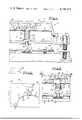
- FIG. 1the front wall 10 of a meter case is provided with the indicator actuation plate 11 securely attached by bolts 12 and surrounded by a flat gasket 13.
- the plateis shown as being centrally recessed and provided with an annular seal 14 to receive the actuation rod of the indicator.
- the encoderis shown generally at 15; it has a back wall 16, front wall 17 and houses a printed circuit board 18, parallel to the walls 16, 17 and spaced about midway between them.
- the encodercomprises also devices which are designed to monitor the gas, electricity or water consumption readings of the meter mechanisms and to transmit coded signals to an outdoor receptacle where they can be read by complementary devices in a probe carried by the meter reader.
- the details of the encoderare not part of the present invention.
- the back wall 16is bored at 19 to permit passage of the actuation rod 20, the wall also being provided with a flanged seat 21 and a sealing ridge 22, adapted to make sealing engagement, respectively, with the seal 14 and gasket 13 when the encoder is mounted on the meter, as by means of the bolts 35.
- the circuit boardis provided with a retaining post 30, a silent contact post 31 and an alarm contact post 32, located relative to each other and to the post 25 on the actuation rod substantially as shown in FIG. 2.
- a contact spring 33is fixed to the board at a terminal 34.
- the spring 33is angled upwardly and outwardly s shown in FIGS. 3, 5 and 7 so that the straight portion 33' normally extends parallel to the surface of the circuit board.
- the post 32is so located relative to post 30 and point 34 that the contact spring, with one side resting against post 30 will be biased into contact with post 32, as shown in FIG. 6.
- Terminal 34 and post 32are connected by wires 36, 37 to a remote alarm device, indicated diagrammatically at 38.
- the act of mounting the encoder on the meterincludes the seating of the seat 21 on the annular seal 14 with the end of rod 20 within the seal; the ridge 22 also seats on the gasket 13, and the respective housings are firmly bolted together by bolts 35.
- the contact of rod 20 with the actuator plate 11 and the relative movement of the latter toward the encodercauses the shoulder 26 to engage the spring 33 and to lift its free end off the post 31, the post 25 at the end of the rod 20 taking over the spring restraining function, with the posts in the position shown in FIGS. 3 and 4. As long as the posts remain in this set position, the alarm circuit is open.
- the rod 40Upon installation of an encoder equipped with this form of the device, the rod 40 is moved by an actuator plate (as in FIG. 3) to a position such that the shoulder 42 lifts the spring arm 48 off the post 43 so that it can rest against the post 41, in the set position. If the encoder is thereafter removed from the meter the rod 40 moves to the FIG. 5 position, permitting the spring end 48 to snap into contact with the post 44, thus closing the alarm circuit.
- the spring end 48is not in the path of movement of the actuating rod, so that replacement of the encoder will not interfere with the alarm indication.
- the encoder with tamper indicator includedis shipped with the actuating element protruding in a position to engage with the actuator plate on the meter.
- an actuating rod 55which is shortened so that it will not protrude from the rear wall 56 of the encoder, which therefore need not be handled with special care.
- the plate 57 on the meteris provided with a pin 58, in a position to engage the end of rod 55 when the devices are assembled, and to cause the actuating rod to function exactly as previously described.
- the seal 59corresponds to the seal 14 and is engaged by the seat 60 on the wall 56.
Landscapes
- Physics & Mathematics (AREA)
- General Physics & Mathematics (AREA)
- Measuring Volume Flow (AREA)
Abstract
Description
Claims (10)
Priority Applications (1)
| Application Number | Priority Date | Filing Date | Title |
|---|---|---|---|
| US05/884,910US4150371A (en) | 1978-03-09 | 1978-03-09 | Tamper indicator |
Applications Claiming Priority (1)
| Application Number | Priority Date | Filing Date | Title |
|---|---|---|---|
| US05/884,910US4150371A (en) | 1978-03-09 | 1978-03-09 | Tamper indicator |
Publications (1)
| Publication Number | Publication Date |
|---|---|
| US4150371Atrue US4150371A (en) | 1979-04-17 |
Family
ID=25385695
Family Applications (1)
| Application Number | Title | Priority Date | Filing Date |
|---|---|---|---|
| US05/884,910Expired - LifetimeUS4150371A (en) | 1978-03-09 | 1978-03-09 | Tamper indicator |
Country Status (1)
| Country | Link |
|---|---|
| US (1) | US4150371A (en) |
Cited By (35)
| Publication number | Priority date | Publication date | Assignee | Title |
|---|---|---|---|---|
| US4274088A (en)* | 1980-05-27 | 1981-06-16 | Pierson Don H | Portable alarm system |
| US4385288A (en)* | 1981-05-04 | 1983-05-24 | Fifth Dimension, Inc. | Motion responsive alarm system |
| US4514683A (en)* | 1982-09-30 | 1985-04-30 | Deibert Richard L | Tamper indicating and theft preventing electrical meter |
| US4542337A (en)* | 1982-09-30 | 1985-09-17 | Honeywell Inc. | Electro-mechanical anti-tampering device for electric meters |
| US4571691A (en)* | 1983-02-16 | 1986-02-18 | Westinghouse Electric Corp. | Watt-hour meter with fiber optics tamper detector |
| US4583483A (en)* | 1982-09-30 | 1986-04-22 | Honeywell Inc. | Mechanical meter tampering indicator |
| US4588949A (en)* | 1983-09-16 | 1986-05-13 | Sangamo Weston, Inc. | Meter removal indicator |
| US4736857A (en)* | 1986-11-14 | 1988-04-12 | American Home Products Corporation | Tamper indicating closure |
| US5140258A (en)* | 1990-12-18 | 1992-08-18 | Micro-Port International Ltd. | Disposable tamper detection device for electricity meters |
| US5293115A (en)* | 1991-08-06 | 1994-03-08 | Schlumberger Industries, Inc. | Method and system for sensing removal of a utility meter from its socket |
| US5646858A (en)* | 1994-03-10 | 1997-07-08 | Analytical Systems Engineering Corp. | Heat apportionment system |
| US5910774A (en)* | 1996-09-18 | 1999-06-08 | Itron, Inc. | Sensor for count and tamper detection |
| FR2777079A1 (en)* | 1998-04-06 | 1999-10-08 | Schlumberger Ind Sa | DEVICE FOR DETECTING THE OPENING OF A COUNTER |
| US6049286A (en)* | 1998-04-24 | 2000-04-11 | Statistical Research, Inc. | Sensor with fall-off detection |
| US6137414A (en)* | 1998-11-30 | 2000-10-24 | Exi Wireless Systems Inc. | Asset security tag |
| US6400269B1 (en) | 1999-12-01 | 2002-06-04 | Anthony Savastano | Firearm alarm |
| US6469626B1 (en)* | 1999-03-02 | 2002-10-22 | First International Computer Inc. | Security system used in an electronic instrument to detect illegal opening of the casing of the electronic instrument |
| US6489890B1 (en)* | 1998-06-16 | 2002-12-03 | Fujitsu Limited | Security device |
| US6618261B1 (en) | 2002-06-04 | 2003-09-09 | Ford Global Technologies, Llc | Electrical sensor mount |
| EP1279841A3 (en)* | 2001-07-24 | 2003-12-03 | Bticino S.P.A. | Wall-mounted electrical apparatus with anti-tamper device |
| US7053774B2 (en) | 2003-09-12 | 2006-05-30 | Alpha Security Products, Inc. | Alarming merchandise display system |
| US20060170549A1 (en)* | 2005-01-14 | 2006-08-03 | Alpha Security Products, Inc. | Portable alarming security device |
| US20070040023A1 (en)* | 2005-08-22 | 2007-02-22 | Aj Ruggirello | Method and apparatus for protecting self service terminals from fraud and tampering |
| US20070040674A1 (en)* | 2005-08-16 | 2007-02-22 | Honeywell International, Inc. | Conductive tamper switch for security devices |
| US20070235470A1 (en)* | 2006-02-20 | 2007-10-11 | Delta Electronics, Inc. | Tamper-evident mechanism |
| FR2901621A1 (en)* | 2006-05-29 | 2007-11-30 | Legrand France | Electrical security apparatus e.g. siren, for e.g. asset, has security units arranged in base, and detecting unit including detector detecting movement of plate between configurations and triggering alarm based on detection of intrusion |
| US20080258708A1 (en)* | 2004-06-15 | 2008-10-23 | Enel Distribuzione S.P.A. | Control Meter with Safety Deactivation |
| US7511470B2 (en) | 2007-01-29 | 2009-03-31 | M&Fc Holding, Llc | Electronic tamper detection circuit for an electricity meter |
| US20090133610A1 (en)* | 2007-11-28 | 2009-05-28 | Baker David L | armed junction box enclosure |
| EP2096608A3 (en)* | 2006-06-13 | 2009-09-16 | Texecom Limited | Adjustable tamper assembly |
| EP2312289A3 (en)* | 2009-10-17 | 2015-01-07 | QUNDIS GmbH | Heating cost distributor |
| US20150041158A1 (en)* | 2010-12-30 | 2015-02-12 | Utc Fire And Security Corporation | Fire safety control system |
| US20160293353A1 (en)* | 2015-04-02 | 2016-10-06 | Lite-On Electronics (Guangzhou) Limited | Switch assembly, switch device having the switch assembly and electronic apparatus having the switch device |
| WO2018004640A1 (en)* | 2016-07-01 | 2018-01-04 | Landis+Gyr Innovations, Inc. | Utility meter enclosure with tamper detection switch |
| WO2021246956A1 (en)* | 2020-06-01 | 2021-12-09 | Ng Choo Boon Alvin | Wearable fluid leakage detection device, system, and method thereof |
Citations (4)
| Publication number | Priority date | Publication date | Assignee | Title |
|---|---|---|---|---|
| US3696371A (en)* | 1971-06-28 | 1972-10-03 | George G Wise | Outboard motor theft alarm having switch actuated by motor clamp |
| US3781857A (en)* | 1972-02-18 | 1973-12-25 | J Stendig | Condition responsive receptacles |
| US3878507A (en)* | 1974-04-15 | 1975-04-15 | Homer L Medlock | Sensor device and alarm circuit for fuel tanks |
| US4047167A (en)* | 1976-08-12 | 1977-09-06 | Helena Bill F | Relaxation switch |
- 1978
- 1978-03-09USUS05/884,910patent/US4150371A/ennot_activeExpired - Lifetime
Patent Citations (4)
| Publication number | Priority date | Publication date | Assignee | Title |
|---|---|---|---|---|
| US3696371A (en)* | 1971-06-28 | 1972-10-03 | George G Wise | Outboard motor theft alarm having switch actuated by motor clamp |
| US3781857A (en)* | 1972-02-18 | 1973-12-25 | J Stendig | Condition responsive receptacles |
| US3878507A (en)* | 1974-04-15 | 1975-04-15 | Homer L Medlock | Sensor device and alarm circuit for fuel tanks |
| US4047167A (en)* | 1976-08-12 | 1977-09-06 | Helena Bill F | Relaxation switch |
Cited By (48)
| Publication number | Priority date | Publication date | Assignee | Title |
|---|---|---|---|---|
| US4274088A (en)* | 1980-05-27 | 1981-06-16 | Pierson Don H | Portable alarm system |
| US4385288A (en)* | 1981-05-04 | 1983-05-24 | Fifth Dimension, Inc. | Motion responsive alarm system |
| US4514683A (en)* | 1982-09-30 | 1985-04-30 | Deibert Richard L | Tamper indicating and theft preventing electrical meter |
| US4542337A (en)* | 1982-09-30 | 1985-09-17 | Honeywell Inc. | Electro-mechanical anti-tampering device for electric meters |
| US4583483A (en)* | 1982-09-30 | 1986-04-22 | Honeywell Inc. | Mechanical meter tampering indicator |
| US4571691A (en)* | 1983-02-16 | 1986-02-18 | Westinghouse Electric Corp. | Watt-hour meter with fiber optics tamper detector |
| US4588949A (en)* | 1983-09-16 | 1986-05-13 | Sangamo Weston, Inc. | Meter removal indicator |
| US4736857A (en)* | 1986-11-14 | 1988-04-12 | American Home Products Corporation | Tamper indicating closure |
| US5140258A (en)* | 1990-12-18 | 1992-08-18 | Micro-Port International Ltd. | Disposable tamper detection device for electricity meters |
| US5293115A (en)* | 1991-08-06 | 1994-03-08 | Schlumberger Industries, Inc. | Method and system for sensing removal of a utility meter from its socket |
| US5646858A (en)* | 1994-03-10 | 1997-07-08 | Analytical Systems Engineering Corp. | Heat apportionment system |
| US5910774A (en)* | 1996-09-18 | 1999-06-08 | Itron, Inc. | Sensor for count and tamper detection |
| FR2777079A1 (en)* | 1998-04-06 | 1999-10-08 | Schlumberger Ind Sa | DEVICE FOR DETECTING THE OPENING OF A COUNTER |
| EP0949511A1 (en)* | 1998-04-06 | 1999-10-13 | Schlumberger Industries S.A. | Device for detecting the opening of a utility meter |
| US6054930A (en)* | 1998-04-06 | 2000-04-25 | Schlumberger Industries, S.A. | Meter tamper detection device capable of counting multiple openings |
| RU2226299C2 (en)* | 1998-04-06 | 2004-03-27 | Шлюмберже Эндюстри С.А. | Device for detecting opening of measuring device |
| US6049286A (en)* | 1998-04-24 | 2000-04-11 | Statistical Research, Inc. | Sensor with fall-off detection |
| US6489890B1 (en)* | 1998-06-16 | 2002-12-03 | Fujitsu Limited | Security device |
| US6137414A (en)* | 1998-11-30 | 2000-10-24 | Exi Wireless Systems Inc. | Asset security tag |
| US6469626B1 (en)* | 1999-03-02 | 2002-10-22 | First International Computer Inc. | Security system used in an electronic instrument to detect illegal opening of the casing of the electronic instrument |
| US6400269B1 (en) | 1999-12-01 | 2002-06-04 | Anthony Savastano | Firearm alarm |
| EP1279841A3 (en)* | 2001-07-24 | 2003-12-03 | Bticino S.P.A. | Wall-mounted electrical apparatus with anti-tamper device |
| US6618261B1 (en) | 2002-06-04 | 2003-09-09 | Ford Global Technologies, Llc | Electrical sensor mount |
| US7053774B2 (en) | 2003-09-12 | 2006-05-30 | Alpha Security Products, Inc. | Alarming merchandise display system |
| US20080258708A1 (en)* | 2004-06-15 | 2008-10-23 | Enel Distribuzione S.P.A. | Control Meter with Safety Deactivation |
| US7692421B2 (en)* | 2004-06-15 | 2010-04-06 | Enel Distribuzione S.P.A. | Control meter with safety deactivation |
| US20060170549A1 (en)* | 2005-01-14 | 2006-08-03 | Alpha Security Products, Inc. | Portable alarming security device |
| US20080061975A1 (en)* | 2005-01-14 | 2008-03-13 | Alpha Security Products, Inc. | Portable alarming security device |
| US7629895B2 (en) | 2005-01-14 | 2009-12-08 | Invue Security Products Inc. | Portable alarming security device |
| US7385522B2 (en) | 2005-01-14 | 2008-06-10 | Invue Security Products Inc. | Portable alarming security device |
| US7388484B2 (en)* | 2005-08-16 | 2008-06-17 | Honeywell International Inc. | Conductive tamper switch for security devices |
| US20070040674A1 (en)* | 2005-08-16 | 2007-02-22 | Honeywell International, Inc. | Conductive tamper switch for security devices |
| US20070040023A1 (en)* | 2005-08-22 | 2007-02-22 | Aj Ruggirello | Method and apparatus for protecting self service terminals from fraud and tampering |
| WO2007024248A1 (en)* | 2005-08-22 | 2007-03-01 | The Wilson Group | Method and apparatus for protecting self service terminals from fraud and tampering |
| US7966964B2 (en)* | 2006-02-20 | 2011-06-28 | Delta Electronics, Inc. | Tamper-evident mechanism |
| US20070235470A1 (en)* | 2006-02-20 | 2007-10-11 | Delta Electronics, Inc. | Tamper-evident mechanism |
| FR2901621A1 (en)* | 2006-05-29 | 2007-11-30 | Legrand France | Electrical security apparatus e.g. siren, for e.g. asset, has security units arranged in base, and detecting unit including detector detecting movement of plate between configurations and triggering alarm based on detection of intrusion |
| EP2096608A3 (en)* | 2006-06-13 | 2009-09-16 | Texecom Limited | Adjustable tamper assembly |
| US7511470B2 (en) | 2007-01-29 | 2009-03-31 | M&Fc Holding, Llc | Electronic tamper detection circuit for an electricity meter |
| US7638998B2 (en) | 2007-01-29 | 2009-12-29 | M&Fc Holding, Llc | Electronic tamper detection circuit for an electricity meter |
| US7671276B2 (en) | 2007-11-28 | 2010-03-02 | Baker David L | Armed junction box enclosure |
| US20090133610A1 (en)* | 2007-11-28 | 2009-05-28 | Baker David L | armed junction box enclosure |
| EP2312289A3 (en)* | 2009-10-17 | 2015-01-07 | QUNDIS GmbH | Heating cost distributor |
| US20150041158A1 (en)* | 2010-12-30 | 2015-02-12 | Utc Fire And Security Corporation | Fire safety control system |
| US20160293353A1 (en)* | 2015-04-02 | 2016-10-06 | Lite-On Electronics (Guangzhou) Limited | Switch assembly, switch device having the switch assembly and electronic apparatus having the switch device |
| US9583286B2 (en)* | 2015-04-02 | 2017-02-28 | Lite-On Electronics (Guangzhou) Limited | Switch carrier with one contact point with a switch including second contact point |
| WO2018004640A1 (en)* | 2016-07-01 | 2018-01-04 | Landis+Gyr Innovations, Inc. | Utility meter enclosure with tamper detection switch |
| WO2021246956A1 (en)* | 2020-06-01 | 2021-12-09 | Ng Choo Boon Alvin | Wearable fluid leakage detection device, system, and method thereof |
Similar Documents
| Publication | Publication Date | Title |
|---|---|---|
| US4150371A (en) | Tamper indicator | |
| US8779933B2 (en) | Status detector and communication unit and system for remote tracking of padlocks | |
| US4542337A (en) | Electro-mechanical anti-tampering device for electric meters | |
| CA2638449C (en) | Tamper detection apparatus for electrical meters | |
| US8701495B2 (en) | Remote fire extinguisher station inspection | |
| US4337466A (en) | Tamper protection for an automatic remote meter reading unit | |
| US7239238B2 (en) | Electronic security seal | |
| US4357601A (en) | Tamper protection for an automatic remote meter reading unit | |
| US4001777A (en) | Taximeter protection system | |
| US4611201A (en) | Magnetically actuated illuminating warning device for circuit breakers | |
| EP0035323A1 (en) | Electricity meters | |
| US7189109B2 (en) | Modular watthour meter socket and test switch | |
| US5867095A (en) | Module tamper detection circuitry | |
| EP0049457B1 (en) | Alarm pull station | |
| US4175813A (en) | Tamper-proof adaptor for an electric meter | |
| US5880667A (en) | System for indicating high temperature event in an electrical power equipment enclosure | |
| CZ61794A3 (en) | Fire-alarm box | |
| US4386314A (en) | Electricity theft preventing meter | |
| US3588866A (en) | Security montioring system with tamperproof cabinet | |
| FR2512993A3 (en) | LUMINOUS DEVICE FOR SIGNALING INCIDENTS IN DOMESTIC ELECTRICAL INSTALLATIONS | |
| US4386313A (en) | Electricity theft preventing meter | |
| US3384886A (en) | Alarm for emergency lighting system | |
| CN211179970U (en) | Universal meter with current measurement error-proofing device | |
| EP0847532A1 (en) | Device for detection of prohibited operation of a measurement equipment | |
| US786912A (en) | Burglar-alarm. |
Legal Events
| Date | Code | Title | Description |
|---|---|---|---|
| AS | Assignment | Owner name:CAPEWELL COMPONENTS COMPANY, CONNECTICUT Free format text:ASSIGNMENT OF ASSIGNORS INTEREST.;ASSIGNOR:RIPLEY COMPANY, INC.;REEL/FRAME:006290/0708 Effective date:19921007 | |
| AS | Assignment | Owner name:FLEET BANK, NATIONAL ASSOCIATION, CONNECTICUT Free format text:ASSIGNMENT OF ASSIGNORS INTEREST;ASSIGNOR:CAPEWELL COMPONENTS COMPANY LIMITED PARTNERSHIP;REEL/FRAME:006891/0579 Effective date:19940217 | |
| AS | Assignment | Owner name:FLEET NATIONAL BANK, CONNECTICUT Free format text:ASSIGNMENT OF ASSIGNORS INTEREST;ASSIGNOR:CAPEWELL COMPONENTS COMPANY LIMITED PARTNERSHIP;REEL/FRAME:008133/0598 Effective date:19960731 | |
| AS | Assignment | Owner name:CAPEWELL COMPONENTS COMPANY, LLC, CONNECTICUT Free format text:ASSIGNMENT OF ASSIGNORS INTEREST;ASSIGNOR:BANK OF AMERICA, N.A., SUCCESSOR BY MERGER TO FLEET NATIONAL BANK, SUCCESSOR INTEREST TO FLEET BANK, NATIONAL ASSOCIATION;REEL/FRAME:017045/0837 Effective date:20050928 |