US4149563A - Anti-cavitation valve - Google Patents
Anti-cavitation valveDownload PDFInfo
- Publication number
- US4149563A US4149563AUS05/769,406US76940677AUS4149563AUS 4149563 AUS4149563 AUS 4149563AUS 76940677 AUS76940677 AUS 76940677AUS 4149563 AUS4149563 AUS 4149563A
- Authority
- US
- United States
- Prior art keywords
- valve
- flow
- passages
- liquid
- trim cage
- Prior art date
- Legal status (The legal status is an assumption and is not a legal conclusion. Google has not performed a legal analysis and makes no representation as to the accuracy of the status listed.)
- Expired - Lifetime
Links
Images
Classifications
- F—MECHANICAL ENGINEERING; LIGHTING; HEATING; WEAPONS; BLASTING
- F16—ENGINEERING ELEMENTS AND UNITS; GENERAL MEASURES FOR PRODUCING AND MAINTAINING EFFECTIVE FUNCTIONING OF MACHINES OR INSTALLATIONS; THERMAL INSULATION IN GENERAL
- F16K—VALVES; TAPS; COCKS; ACTUATING-FLOATS; DEVICES FOR VENTING OR AERATING
- F16K47/00—Means in valves for absorbing fluid energy
- F16K47/08—Means in valves for absorbing fluid energy for decreasing pressure or noise level and having a throttling member separate from the closure member, e.g. screens, slots, labyrinths
- F—MECHANICAL ENGINEERING; LIGHTING; HEATING; WEAPONS; BLASTING
- F16—ENGINEERING ELEMENTS AND UNITS; GENERAL MEASURES FOR PRODUCING AND MAINTAINING EFFECTIVE FUNCTIONING OF MACHINES OR INSTALLATIONS; THERMAL INSULATION IN GENERAL
- F16K—VALVES; TAPS; COCKS; ACTUATING-FLOATS; DEVICES FOR VENTING OR AERATING
- F16K3/00—Gate valves or sliding valves, i.e. cut-off apparatus with closing members having a sliding movement along the seat for opening and closing
- F16K3/30—Details
- F16K3/34—Arrangements for modifying the way in which the rate of flow varies during the actuation of the valve
- Y—GENERAL TAGGING OF NEW TECHNOLOGICAL DEVELOPMENTS; GENERAL TAGGING OF CROSS-SECTIONAL TECHNOLOGIES SPANNING OVER SEVERAL SECTIONS OF THE IPC; TECHNICAL SUBJECTS COVERED BY FORMER USPC CROSS-REFERENCE ART COLLECTIONS [XRACs] AND DIGESTS
- Y10—TECHNICAL SUBJECTS COVERED BY FORMER USPC
- Y10T—TECHNICAL SUBJECTS COVERED BY FORMER US CLASSIFICATION
- Y10T137/00—Fluid handling
- Y10T137/8593—Systems
- Y10T137/86493—Multi-way valve unit
- Y10T137/86718—Dividing into parallel flow paths with recombining
- Y10T137/86734—With metering feature
- Y—GENERAL TAGGING OF NEW TECHNOLOGICAL DEVELOPMENTS; GENERAL TAGGING OF CROSS-SECTIONAL TECHNOLOGIES SPANNING OVER SEVERAL SECTIONS OF THE IPC; TECHNICAL SUBJECTS COVERED BY FORMER USPC CROSS-REFERENCE ART COLLECTIONS [XRACs] AND DIGESTS
- Y10—TECHNICAL SUBJECTS COVERED BY FORMER USPC
- Y10T—TECHNICAL SUBJECTS COVERED BY FORMER US CLASSIFICATION
- Y10T137/00—Fluid handling
- Y10T137/8593—Systems
- Y10T137/86493—Multi-way valve unit
- Y10T137/86718—Dividing into parallel flow paths with recombining
- Y10T137/86759—Reciprocating
- Y10T137/86791—Piston
Definitions
- cavitation within the valveis always a matter of serious concern. Where excessive cavitation occurs, a throttling valve may be literally destroyed within a few hours of operation. Cavitation results from the fact that, during throttling of a liquid under pressure, the pressure drop of the liquid in the region of the throttling orifices tends to fall momentarily below the vapor pressure of the liquid. In the typical situation, where water is the control fluid, this causes the momentary formation of steam bubbles just downstream of the throttling surfaces.
- a novel and improved throttling valvein which, in addition to generally minimizing the cavitation energies in accordance with known procedures, the valve is so designed and costructed as to locate the sites of bubble implosion in regions as remote as practicable from the valve parts in order to minimize the cavitation damage resulting from the bubble implosions, which are somewhat unavoidable.
- the cavitation damage resulting from bubble implosionis an exponential function of the distance between the implosion site and the adjacent metal surfaces, such that increasing the distance between valve walls and implosion sites exponentially decreases the effect of the resulting shock wave on the valve parts.
- a throttling valve in accordance with the above objectiveis provided with a cylindrical trim cage receiving a controllably positioned cylindrical valve plug.
- the trim cageis provided with a plurality of radial passages, of special configuration to be described, to permit the radially inward flow of liquid.
- each of the radial passagesis of a configuration such that the effective throttling orifice formed thereby is located as close as practicable to the inner wall surface of the trim cage.
- the liquidboth accelerates and contracts its flow stream as it approaches the effective orifice. After passing through the effective orifice, the flow stream continues to accelerate and contract for a predetermined distance, after which it begins to decelerate and expand.
- the region of lowest pressure of the fluidis the point at which the flow stream is most contracted and traveling at the highest velocity, in other words at the so-called vena contracta. If the pressure in the region of the vena contracta is below the vapor pressure of the liquid, which is often the case in practical applications, bubbles will form.
- the implosion sites of the bubblestypically are located slightly on the downstream side of the vena contracta.
- the vena contractawill be formed closer to the wall than desired and, perhaps, even within the wall, so that the resulting implosion downstream of the vena contracta can occur closely adjacent to the valve surfaces, tending to cause excessive cavitation damage.
- a novel and improved throttling valvein which a cylindrical trim cage is formed with a plurality of radial passages, of a generally exponentially converging configuration, yet which is capable of being produced in a practical manner utilizing conventional machining equipment.
- a theoretically ideal, exponentially converging radial passageis closely approximated by forming the passages in three stages.
- the innermost stagecomprises the primary throttling orifice and is substantially cylindrical in form, of minimum but finite length.
- the second stagemay be of substantially straight-walled conical form joining, at its convergent end, with the orifices section and expanding in a generally radially outward direction therefrom.
- the third stage of the passageis an arcuate outward flare, which is substantially tangent with the divergent end of the conical section and merges more or less into tangency with the outer walls of the trim cage.
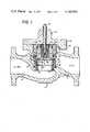
- FIG. 1is a longitudinal cross sectional view of a typical form of high pressure liquid throttling valve constructed in accordance with the principles of the invention.
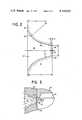
- FIG. 2is a greatly enlarged, fragmentary cross sectional view of the trim cage incorporated in the valve of FIG. 1, illustrating details of the configuration of fluid passages therein.
- FIG. 3is an enlarged, fragmentary cross sectional view illustrating the relationship of the new trim cage fluid passages in conjunction with an axially recessed valve plug.
- the reference numeral 10designates generally a valve body of a fluid control valve, such as might be used in controlling the flow of water under high pressure, for example, as in a boiler feed system.
- the valve bodyhas an inlet passage 11 and an outlet passage 12. Dividing and separating the inlet and outlet passages is an internal web 13 provided with an opening 14 forming a valve passage and mounting the primary valve parts.
- a generally cylindrical trim cage 15Seated within the web passage 14 is a generally cylindrical trim cage 15 having an extension 16 of reduced diameter extending into the web opening 14 and having a shoulder 17 seated in sealed relation against a corresponding shoulder 18 formed on the dividing web 13.
- a balancing cylinder 19is seated on top of the trim cage 15 and extends from the top of the trim cage to and in contact with lower surfaces 20 of the valve bonnet 21.
- the bonnet 21typically is secured to the valve body 10 by flanges 22, 23 of the bonnet and valve body respectively, which may be bolted together in a conventional manner.
- the trim cage 15, balancing cylinder 19, web 13 and bonnet 21form a sealed assembly, such that fluid flowing from the inlet passage 11 to the outlet passage 12 is required to flow in a controlled manner through openings 24 (to be described) in the trim cage.
- the configuration of the valve bodyis such as to provide fluid access to the trim cage about its entire outer cylindrical surface, so that fluid may flow radially inward through the openings 24 from all sides of the trim cage.
- a balanced valve plug 25is slideably received within the trim cage 15 and balancing cylinder 19 for controlled vertical positioning.
- the upper end 26 of the valve plugis of slightly reduced diameter and is slideably guided by the balancing cylinder 19.
- the lower portion 27 of the valve plugis of slightly enlarged diameter and is arranged to be slideably guided within the trim cage.
- the lower end of the valve plugadjacent its outer wall, is provided with a tapered annular valve surface 28 arranged for cooperation with a similarly tapered annular valve seat 29 in the lower portion of the trim cage. The arrangement is such that, when the plug 25 is in its lowermost position, the valve surface 28 mates with this valve seat 29 to completely close the valve.
- valve stem 30which extends up through the bonnet 21 and is connected to a suitable actuator (not shown) such as a threaded hand wheel or a pilot actuator.
- a suitable actuatorsuch as a threaded hand wheel or a pilot actuator.
- the lower end of the valve stem 30extends slideably through a bushing 31, which is threadedly received within an internal recess 32 in the valve plug.
- the valve stemis connected to a pilot plug 33, which is adapted for limited vertical movement relative to the valve plug, between an open position, as illustrated in FIG. 1, in which the upper end of the pilot plug is abutted against the bushing 31, and a closed position in which the lower end of the pilot plug is seated in an opening 34 in the bottom of the valve plug.
- valve stem 30 and the pilot plug 33are moved downwardly.
- a bleed passage 35is provided in the upper wall of the trim cage 15, communicating with an annular area 36 above the shoulder 37 formed by the enlarged lower end 27 of the plug.
- downstream (lower) pressureacts on the bottom face of the plug and also on the reduced-area upper end, providing a net downward bias from high pressure acting on the shoulder 37.
- valve plug clearances with the balancing cylinder 19are such as to permit leakage of the upstream pressure into the area 38 directly above the upper end of the valve plug tending to urge the plug in a downward direction.
- the stem 30In order to open the valve plug, the stem 30 is controllably raised. Initially, this will serve to withdraw the pilot plug 33 from the opening 34, connecting the upper chamber 38 to the downstream pressure, through the recess 32 and bushing passages 39. This reduces the pressure unbalance on the plug to a predetermined bias resulting from the upstream pressure acting upon the shoulder 37. Continued, controlled upward movement of the valve stem 30 causes the pilot plug 33 to seat against the lower surface of the bushing 31 and then to mechanically lift the valve plug against the downward biasing pressure against the shoulder 37. In any position of the valve other than fully closed, the valve plug is slightly biased in a closing direction by pressure against the shoulder 37, while being mechanically restrained by the valve stem 30.
- the plugcan be controllably moved and retained in any desired position by manipulation of the stem 30.
- This manner of controlling the position of the valve plugis, of course, well known in the art and is reflected in, for example, the Schnall U.S. Pat. No. 3,575,213.
- the trim cage 15 and valve plug 25 of the valveare constructed in a novel and unique manner to enable the valve to be utilized in difficult environments, such as the control of the flow of high temperature water under high pressure conditions without excessive cavitation damage.
- the valveis constructed in accordance with unique principles, such that the nature and location of the vena contracta in relation to surfaces within the valve structure signicantly minimizes cavitation damage to the valve components.
- cavitation damage in a high pressure liquid throttling valveis a function of the size of the vena contracta and also the distance of the vena contracta from adjacent valve surfaces.
- the radial fluid flow passages 24 in the trim cage 15are constructed and arranged in accordance with novel principles such that, while subdividing the fluid flow into a multiplicity of passages, the vena contracta may at the same time be positioned as far as practicable from any surface of the valve for optimum minimization of cavitation damage.
- the fluid passages 24are so constructed and contoured that the effective orifice is located as close as practicable to the inner wall surface of the trim cage, causing the vena contracta formation to be as far removed from such surface as is practicable under the circumstances.
- FIG. 2 of the drawinga greatly enlarged fragmentary section of the trim cage 15 is illustrated, showing details of a single radial fluid flow passage 24.
- the present inventionis based upon the observation that a liquid under high pressure, in flowing through a restricted orifice, will approach the orifice in a progressively converging flow path, with the fluid within that path gradually increasing in velocity.
- the liquidfollows an exponentially converging flow path, the outer contours of which are more or less parabolic in regions close to the effective orifice.
- the desired orificeis formed as close as practicable to the inner wall surface 40 of the trim cage, and the inlet passage areas leading to the orifice are formed substantially to follow the theoretically ideal exponentially converging configuration.
- a significant aspect of the inventionresides in so forming the inlet regions 41 of the flow passages 24 that the liquid can follow its natural, exponentially converging flow path to the orifice, designated 42 in FIG. 2, located closely adjacent the inner wall 40.
- the orifice opening 42is the smallest diameter portion of the passage 24
- any part of the inlet region 41 of the passageis of significantly smaller diameter than the exponentially converging envelope, that smaller diameter portion, even though substantially larger than the orifice opening 42, will become an effective orifice in the passage, setting up a vena contracta close to the wall of the trim cage and perhaps even within the passage itself, so that significant cavitation damage can be expected under severe operating conditions.
- the flow passages 24By forming the flow passages 24 with an exponentially decreasing contour leading up to the effective orifice 42 closely adjacent the inner wall 40, the liquid flowing radially inward through the passage issues from the orifice 42 at high velocity, continuing to converge slightly for a distance beyond the wall 40. This is reflected in the flow path lines shown as arrows flowing left to right through the orifice 42 in FIG. 2. At a certain point, spaced inward from the wall 40, the flow reaches a maximum velocity and a minimum diameter, and this point is referred to as the vena contracta, being indicated by the vertical line labeled "VC".
- the pressure in the flowing fluidis at its minimum and, if it is below the vapor pressure of the liquid, as is often the case, bubbles will form in the liquid and the stream will begin to loose integrity.
- the flowing liquidlooses velocity and increases in pressure, and the bubbles, if formed, will collapse and implode as the pressure builds up to exceed the vapor pressure level.
- the annular rib 43forming the lowermost extremity of the valve plug, may be located closely adjacent to one or more of the inlet passages 24 of the trim cage.
- the inlet passages 24are formed in accordance with the above described aspects of the invention, to locate the vena contracta as far as practicable inside the inner wall 40 of the trim cage, the bubble implosion sites could still be located closely adjacent to the end surface of an unrecessed plug 25.
- the plug end faceis recessed at 44, at least in an annular region adjacent to the vena contracta "VC" and the related bubble implosion sites, and preferably over the entire end surface of the plug circumscribed by the annular rib 43.
- valve plugs with recessed end faceshave been utilized heretofore in other contexts, there is particular significance in the utilization of such recessed end faces in conjunction with inwardly displaced vena contracta pursuant to the present invention.
- a valve in which the trim cage has inlet passages of conventional configurationforming vena contracta which are not significantly displaced inwardly from the inner wall surface of the trim cage, little of any advantage would be realized from the utilization of a recess end face on the valve plug, as will be appreciated.
- Throttling valves of the type herein contemplatedtypically are of relatively large diameter, intended for high pressure, high temperature service in industrial applications, such as in connection with public utility power generating equipment and the like. Accordingly, the valves frequently may be of custom or partially custom design, such that large production runs of identical devices is not a normal expectation. Accordingly, as a further and more specific feature of the invention, the design of the fluid flow passages 24 is such as to enable the desired exponentially converging flow path to be closely approximated, while at the same time enabling the article to be machined on a custom or partly custom basis with relatively uncomplicated and economical tooling and machining techniques. To this end, the contours of the passage are not purely exponential, but are a combination of radiused and straight line portions, in conjunction with a short but finite generally cylindrical section at the inner wall extremity.
- the inlet passage 24is typically formed of three stages, a short but finite cylindrical section 45, whose diameter is equal to the diameter of the desired effective orifice 42.
- the cylindrical section 45is located immediately adjacent the inner wall 40 of the trim cage.
- Connecting the short cylindrical section 45is an outwardly divergent conical section 46, and joining the conical section is an outwardly flaring radiused section 47, which merges into substantial tangency with the conically diverging section 46, and joins with the outer surface 48 of the trim cage.
- the outwardly flaring section 47may merge into substantial tangency with the outer surface portions of the trim cage, but this is not necessary and may be indeed even be precluded by the closeness of adjacent passages.
- the provision of the short but finite cylindrical section 45has practical significance in that it assures uniformity in the final diameter of the orifice. Were the conically divergent portion 46 to be machined through to the inner wall 40, expected variations in the depth of the machining operations would result in variations in the diameter of the opening, which could be undesirable.
- the axial length of the cylindrical portion 45is sufficient only to provide a reasonable machining tolerance while assuring uniformity in the diameter of the holes. In practice, an axial length of about 0.8 mm has been found to be ample for substantially all typical sizes of the valve. This axial length is indicated by the letter "t" in FIG. 2.
- the diameter "D" of the effective orifice 42desirably has an optimum relationship with the thickness "T" of the wall of the cylindrical trim cage 15, in order to reasonably accommodate an exponentially converging flow path to the orifice.
- a relatively small diameter valvee.g., 50-75 mm
- the orifice diametertypically might be around 2.4 mm
- the wall thicknesstypically might be on the order of around 5.5 mm.
- a very large valvee.g., around 350 mm
- the orifice diameter "D”typically might be on the order of 18 mm
- the thickness of the trim cage wallmight be on the order of 45 mm.
- the optimum ratio of trim cage wall thickness "T" to orifice diameter "D”is usually greater than two to one, but generally does not significantly exceed 2.5 to one.
- the desired exponentially converging flow pathmay be adequately approximated in the conically divergent region 46 by forming a conical section with a 30° included angle. That is, the angle ⁇ between the wall and the central axis, will be about 15°. This angle appears to be appropriate for the complete typical size range of valves.
- the center of curvature and the radius of the outwardly flaring portion 47 of the flow passageadvantageously may be determined by observing optimum ratios with respect to the orifice diameter "D".
- the radius "r" of curvature at the inlet endtypically may be about twice the diameter of the orifice, for all valve sizes.
- the center of curvatureis spaced inward from the outer wall extremity 48 a distance "d" equal to about 1.75-1.85 times the orifice diameter "D" for a typical range of valve sizes. Having established this distance "d", the center of curvature may be located precisely by commencing the arc in tangency with the conically divergent section 46.
- the improved valve construction of the inventionprovides a highly efficient throttling valve for high pressure, high temperature liquid service, in which cavitation damage is significantly reduced by so contouring the trim cage flow passages that the vena contracta of the individual flow streams are removed as far as practicable from any metal surfaces of the valve.
Landscapes
- Engineering & Computer Science (AREA)
- General Engineering & Computer Science (AREA)
- Mechanical Engineering (AREA)
- Sliding Valves (AREA)
- Details Of Valves (AREA)
- Lift Valve (AREA)
Abstract
Description
Claims (9)
Priority Applications (7)
| Application Number | Priority Date | Filing Date | Title |
|---|---|---|---|
| US05/769,406US4149563A (en) | 1977-02-16 | 1977-02-16 | Anti-cavitation valve |
| CA295,764ACA1079253A (en) | 1977-02-16 | 1978-01-26 | Anti-cavitation valve |
| GB3714/78AGB1573890A (en) | 1977-02-16 | 1978-01-30 | Anticavitation valve |
| FR7804275AFR2381219A1 (en) | 1977-02-16 | 1978-02-15 | ANTIAVITATION VALVE, ESPECIALLY FOR ADJUSTING THE FLOW RATE OF A HIGH PRESSURE LIQUID |
| IT67309/78AIT1108076B (en) | 1977-02-16 | 1978-02-15 | ANTI-CAVITATION VALVE FOR THE ADJUSTMENT OF THE FLOW OF A LIQUID UNDER HIGH PRESSURE |
| JP53015514AJPS6039911B2 (en) | 1977-02-16 | 1978-02-15 | anti cavitation valve |
| ES466990AES466990A1 (en) | 1977-02-16 | 1978-02-15 | Anti-cavitation valve |
Applications Claiming Priority (1)
| Application Number | Priority Date | Filing Date | Title |
|---|---|---|---|
| US05/769,406US4149563A (en) | 1977-02-16 | 1977-02-16 | Anti-cavitation valve |
Publications (1)
| Publication Number | Publication Date |
|---|---|
| US4149563Atrue US4149563A (en) | 1979-04-17 |
Family
ID=25085349
Family Applications (1)
| Application Number | Title | Priority Date | Filing Date |
|---|---|---|---|
| US05/769,406Expired - LifetimeUS4149563A (en) | 1977-02-16 | 1977-02-16 | Anti-cavitation valve |
Country Status (7)
| Country | Link |
|---|---|
| US (1) | US4149563A (en) |
| JP (1) | JPS6039911B2 (en) |
| CA (1) | CA1079253A (en) |
| ES (1) | ES466990A1 (en) |
| FR (1) | FR2381219A1 (en) |
| GB (1) | GB1573890A (en) |
| IT (1) | IT1108076B (en) |
Cited By (38)
| Publication number | Priority date | Publication date | Assignee | Title |
|---|---|---|---|---|
| US4498213A (en)* | 1981-02-17 | 1985-02-12 | White Consolidated Industries, Inc. | Soot blower |
| US4569370A (en)* | 1983-11-14 | 1986-02-11 | Best Industries, Inc. | Balanced double cage choke valve |
| US4825906A (en)* | 1988-06-06 | 1989-05-02 | Hartman Thomas A | Angle pattern control valve |
| US5209259A (en)* | 1991-01-15 | 1993-05-11 | E. I. Du Pont De Nemours And Company | Fluid distribution system having noise reduction mechanism |
| ES2120827A1 (en)* | 1994-11-29 | 1998-11-01 | Valcontrol S A | Anti-cavitation system in control valves |
| WO1999061830A1 (en)* | 1998-05-21 | 1999-12-02 | Cairnscorp Technology Pty. Limited | A flow restriction device |
| WO2002090806A1 (en)* | 2001-05-07 | 2002-11-14 | Fisher Controls International Llc | High performance fluid control valve |
| US6536467B2 (en) | 2000-12-05 | 2003-03-25 | National-Oilwell, L.P. | Valve with increased inlet flow |
| US20030159737A1 (en)* | 2002-02-22 | 2003-08-28 | Dresser, Inc. | High capacity globe valve |
| US6715505B2 (en) | 2000-11-30 | 2004-04-06 | Dresser, Inc. | Steam pressure reducing and conditioning valve |
| US6742773B2 (en) | 2000-11-30 | 2004-06-01 | Dresser, Inc. | Steam pressure reducing and conditioning valve |
| US6758232B2 (en) | 2000-11-30 | 2004-07-06 | Dresser, Inc. | Steam pressure reducing and conditioning system |
| US6766826B2 (en)* | 2002-04-12 | 2004-07-27 | Fisher Controls International, Inc. | Low noise fluid control valve |
| US20050034770A1 (en)* | 2003-08-15 | 2005-02-17 | Stares James Albert | Fluid flow regulation |
| US20050061375A1 (en)* | 2002-12-19 | 2005-03-24 | Fisher Controls International Llc | Control valve with low noise and enhanced flow characteristics |
| US20070227600A1 (en)* | 2006-03-28 | 2007-10-04 | Bermad Limited Partnership | Control valve with integrated insert providing valve seat and plug guides |
| US20090026395A1 (en)* | 2007-07-25 | 2009-01-29 | Aaron Andrew Perrault | Apparatus to increase fluid flow in a valve |
| US20090179169A1 (en)* | 2008-01-11 | 2009-07-16 | Fleming Leslie E | Seal assembly for use with valves having a two-piece cage |
| US20090217996A1 (en)* | 2005-12-29 | 2009-09-03 | Imi Vision Limited | Fluid Control |
| CN1668869B (en)* | 2002-07-17 | 2011-09-07 | 费希尔控制国际公司 | Improved skirt pilot valve |
| US20120285546A1 (en)* | 2009-07-30 | 2012-11-15 | Twister B.V. | Tapered throttling valve |
| CN102913679A (en)* | 2012-11-02 | 2013-02-06 | 济南大学 | Low-noise regulating valve |
| CN102937192A (en)* | 2012-10-26 | 2013-02-20 | 珠海艾迪西软件科技有限公司 | Two-way valve |
| US8833384B2 (en) | 2012-08-06 | 2014-09-16 | Schneider Electric Buildings, Llc | Advanced valve actuation system with integral freeze protection |
| CN104048102A (en)* | 2014-06-18 | 2014-09-17 | 中国船舶重工集团公司第七○二研究所 | Low noise control valve |
| WO2014178723A1 (en) | 2013-04-29 | 2014-11-06 | Typhonix As | Flow and fluid conditioning pressure reducing valve or device |
| RU2542726C2 (en)* | 2009-06-08 | 2015-02-27 | Фишер Контролз Интернешнел Ллс | Hydraulic valve with dynamic connection of valve gate |
| CN104428568A (en)* | 2012-04-12 | 2015-03-18 | 诺沃皮尼奥内股份有限公司 | Valve |
| US20150275612A1 (en)* | 2014-01-24 | 2015-10-01 | Cameron International Corporation | Low shear trim |
| WO2016069965A1 (en)* | 2014-10-31 | 2016-05-06 | Fisher Controls International Llc | Noise reducing diffuser trim |
| US20160312917A1 (en)* | 2015-04-21 | 2016-10-27 | Fisher Controls International Llc | Noise reducing diffuser trim with chevrons |
| US9534795B2 (en) | 2012-10-05 | 2017-01-03 | Schneider Electric Buildings, Llc | Advanced valve actuator with remote location flow reset |
| US9658628B2 (en) | 2013-03-15 | 2017-05-23 | Schneider Electric Buildings, Llc | Advanced valve actuator with true flow feedback |
| US20170234440A1 (en)* | 2016-02-17 | 2017-08-17 | Vag - Armaturen Gmbh | Control cylinder for a control valve and control valve comprising such a control cylinder |
| US20170268697A1 (en)* | 2016-03-21 | 2017-09-21 | Fisher Controls International Llc | Cage apparatus having fluid passageways to affect flow characteristics of valves |
| US20180010696A1 (en)* | 2016-07-08 | 2018-01-11 | Emerson Process Management (Tianjin) Valves Co., Ltd | Cascaded controllable fluid control valve and valve trim for a fluid control valve |
| US10007239B2 (en) | 2013-03-15 | 2018-06-26 | Schneider Electric Buildings Llc | Advanced valve actuator with integral energy metering |
| US10295080B2 (en) | 2012-12-11 | 2019-05-21 | Schneider Electric Buildings, Llc | Fast attachment open end direct mount damper and valve actuator |
Families Citing this family (9)
| Publication number | Priority date | Publication date | Assignee | Title |
|---|---|---|---|---|
| US4236547A (en)* | 1979-04-09 | 1980-12-02 | Ogontz Controls Company | Self-cleaning valve plug and seat assembly |
| FR2496825A1 (en)* | 1980-12-23 | 1982-06-25 | Sereg Soc | CAGE CONTROL VALVE AND PILOT VALVE |
| FR2567984B1 (en)* | 1984-07-20 | 1986-08-14 | Centre Techn Ind Mecanique | PROPORTIONAL HYDRAULIC DISTRIBUTOR |
| JPS61206873A (en)* | 1985-03-12 | 1986-09-13 | Niigata Meesonneeran Kk | Valve piece structure of multihole cage adjusting valve |
| GB8700111D0 (en)* | 1987-01-06 | 1987-02-11 | Scott R M | Fluid flow control valves |
| DE3717128A1 (en)* | 1987-05-21 | 1988-12-08 | Welland & Tuxhorn Armaturen Un | FLOW CONTROL VALVE FOR A LIQUID OR GASEOUS FLOW MEDIUM |
| JPH073263B2 (en)* | 1992-10-09 | 1995-01-18 | 日本ベーレー株式会社 | High differential pressure control valve |
| US6244297B1 (en)* | 1999-03-23 | 2001-06-12 | Fisher Controls International, Inc. | Fluid pressure reduction device |
| GB2618602B (en)* | 2022-05-12 | 2024-08-07 | Goodwin Plc | Trim component and valve |
Citations (4)
| Publication number | Priority date | Publication date | Assignee | Title |
|---|---|---|---|---|
| DE1050626B (en)* | 1959-02-12 | |||
| US3605787A (en)* | 1969-12-04 | 1971-09-20 | Chas M Bailey Co Inc | Polyjet valve |
| US3776278A (en)* | 1971-06-29 | 1973-12-04 | Fisher Controls Co | Valve including noise reducing means |
| US3880399A (en)* | 1974-04-01 | 1975-04-29 | Fisher Controls Co | Multistage noise reducing flow control valve |
Family Cites Families (6)
| Publication number | Priority date | Publication date | Assignee | Title |
|---|---|---|---|---|
| NL13901C (en)* | 1900-01-01 | |||
| US3813079A (en)* | 1971-12-10 | 1974-05-28 | Masoneilan Int Inc | Quick change apparatus for effecting gas flow pressure reduction with low noise generator |
| FR2187083A5 (en)* | 1972-05-31 | 1974-01-11 | Alsthom Cgee | |
| JPS5545939Y2 (en)* | 1975-02-14 | 1980-10-28 | ||
| DE7606041U1 (en)* | 1976-02-28 | 1977-08-25 | Fa. Carl Freudenberg, 6940 Weinheim | Torsional vibration damper |
| FR2362320A1 (en)* | 1976-08-16 | 1978-03-17 | Kubota Ltd | Sleeve valve with outside perforated sleeve - has perforations accommodating shrink fit nozzles with converging bores running radially of sleeve |
- 1977
- 1977-02-16USUS05/769,406patent/US4149563A/ennot_activeExpired - Lifetime
- 1978
- 1978-01-26CACA295,764Apatent/CA1079253A/ennot_activeExpired
- 1978-01-30GBGB3714/78Apatent/GB1573890A/ennot_activeExpired
- 1978-02-15FRFR7804275Apatent/FR2381219A1/enactiveGranted
- 1978-02-15ESES466990Apatent/ES466990A1/ennot_activeExpired
- 1978-02-15JPJP53015514Apatent/JPS6039911B2/ennot_activeExpired
- 1978-02-15ITIT67309/78Apatent/IT1108076B/enactive
Patent Citations (4)
| Publication number | Priority date | Publication date | Assignee | Title |
|---|---|---|---|---|
| DE1050626B (en)* | 1959-02-12 | |||
| US3605787A (en)* | 1969-12-04 | 1971-09-20 | Chas M Bailey Co Inc | Polyjet valve |
| US3776278A (en)* | 1971-06-29 | 1973-12-04 | Fisher Controls Co | Valve including noise reducing means |
| US3880399A (en)* | 1974-04-01 | 1975-04-29 | Fisher Controls Co | Multistage noise reducing flow control valve |
Cited By (65)
| Publication number | Priority date | Publication date | Assignee | Title |
|---|---|---|---|---|
| US4498213A (en)* | 1981-02-17 | 1985-02-12 | White Consolidated Industries, Inc. | Soot blower |
| US4569370A (en)* | 1983-11-14 | 1986-02-11 | Best Industries, Inc. | Balanced double cage choke valve |
| US4825906A (en)* | 1988-06-06 | 1989-05-02 | Hartman Thomas A | Angle pattern control valve |
| US5209259A (en)* | 1991-01-15 | 1993-05-11 | E. I. Du Pont De Nemours And Company | Fluid distribution system having noise reduction mechanism |
| ES2120827A1 (en)* | 1994-11-29 | 1998-11-01 | Valcontrol S A | Anti-cavitation system in control valves |
| WO1999061830A1 (en)* | 1998-05-21 | 1999-12-02 | Cairnscorp Technology Pty. Limited | A flow restriction device |
| US6742773B2 (en) | 2000-11-30 | 2004-06-01 | Dresser, Inc. | Steam pressure reducing and conditioning valve |
| US6715505B2 (en) | 2000-11-30 | 2004-04-06 | Dresser, Inc. | Steam pressure reducing and conditioning valve |
| US6758232B2 (en) | 2000-11-30 | 2004-07-06 | Dresser, Inc. | Steam pressure reducing and conditioning system |
| US6536467B2 (en) | 2000-12-05 | 2003-03-25 | National-Oilwell, L.P. | Valve with increased inlet flow |
| US6536472B2 (en)* | 2001-05-07 | 2003-03-25 | Fisher Controls International, Inc. | High performance fluid control valve |
| US6701958B2 (en) | 2001-05-07 | 2004-03-09 | Fisher Controls International, Inc. | High performance fluid control valve |
| WO2002090806A1 (en)* | 2001-05-07 | 2002-11-14 | Fisher Controls International Llc | High performance fluid control valve |
| US20030159737A1 (en)* | 2002-02-22 | 2003-08-28 | Dresser, Inc. | High capacity globe valve |
| US6935371B2 (en) | 2002-02-22 | 2005-08-30 | Dresser, Inc. | High capacity globe valve |
| US6766826B2 (en)* | 2002-04-12 | 2004-07-27 | Fisher Controls International, Inc. | Low noise fluid control valve |
| CN1668869B (en)* | 2002-07-17 | 2011-09-07 | 费希尔控制国际公司 | Improved skirt pilot valve |
| US6973941B2 (en)* | 2002-12-19 | 2005-12-13 | Fisher Controls International Llc | Control valve with low noise and enhanced flow characteristics |
| US20050061375A1 (en)* | 2002-12-19 | 2005-03-24 | Fisher Controls International Llc | Control valve with low noise and enhanced flow characteristics |
| US7104281B2 (en) | 2003-08-15 | 2006-09-12 | Dresser, Inc. | Fluid flow regulation |
| US20050034770A1 (en)* | 2003-08-15 | 2005-02-17 | Stares James Albert | Fluid flow regulation |
| US8474484B2 (en) | 2005-12-29 | 2013-07-02 | Imi Vision Limited | Fluid control |
| US20090217996A1 (en)* | 2005-12-29 | 2009-09-03 | Imi Vision Limited | Fluid Control |
| US20070227600A1 (en)* | 2006-03-28 | 2007-10-04 | Bermad Limited Partnership | Control valve with integrated insert providing valve seat and plug guides |
| US7458393B2 (en)* | 2006-03-28 | 2008-12-02 | Bermad Cs, Ltd | Control valve with integrated insert providing valve seat and plug guides |
| US20080314463A1 (en)* | 2006-03-28 | 2008-12-25 | Bermad Cs Ltd. | Control valve with integrated insert providing valve seat and plug guides |
| US20090026395A1 (en)* | 2007-07-25 | 2009-01-29 | Aaron Andrew Perrault | Apparatus to increase fluid flow in a valve |
| WO2009015094A1 (en)* | 2007-07-25 | 2009-01-29 | Fisher Controls International Llc | Valve with cage |
| EP2489910A1 (en)* | 2007-07-25 | 2012-08-22 | Fisher Controls International Llc | Valve with cage |
| US20090179169A1 (en)* | 2008-01-11 | 2009-07-16 | Fleming Leslie E | Seal assembly for use with valves having a two-piece cage |
| RU2542726C2 (en)* | 2009-06-08 | 2015-02-27 | Фишер Контролз Интернешнел Ллс | Hydraulic valve with dynamic connection of valve gate |
| US9625055B2 (en)* | 2009-07-30 | 2017-04-18 | Twister B.V. | Tapered throttling valve |
| US20120285546A1 (en)* | 2009-07-30 | 2012-11-15 | Twister B.V. | Tapered throttling valve |
| US9638342B2 (en)* | 2012-04-12 | 2017-05-02 | Nuovo Pignone Srl | Control valve for gas and liquids |
| US20150114498A1 (en)* | 2012-04-12 | 2015-04-30 | Nuovo Pignone Srl | Valve |
| CN104428568A (en)* | 2012-04-12 | 2015-03-18 | 诺沃皮尼奥内股份有限公司 | Valve |
| US8833384B2 (en) | 2012-08-06 | 2014-09-16 | Schneider Electric Buildings, Llc | Advanced valve actuation system with integral freeze protection |
| US9534795B2 (en) | 2012-10-05 | 2017-01-03 | Schneider Electric Buildings, Llc | Advanced valve actuator with remote location flow reset |
| CN102937192A (en)* | 2012-10-26 | 2013-02-20 | 珠海艾迪西软件科技有限公司 | Two-way valve |
| CN102913679A (en)* | 2012-11-02 | 2013-02-06 | 济南大学 | Low-noise regulating valve |
| US10295080B2 (en) | 2012-12-11 | 2019-05-21 | Schneider Electric Buildings, Llc | Fast attachment open end direct mount damper and valve actuator |
| US10007239B2 (en) | 2013-03-15 | 2018-06-26 | Schneider Electric Buildings Llc | Advanced valve actuator with integral energy metering |
| US9658628B2 (en) | 2013-03-15 | 2017-05-23 | Schneider Electric Buildings, Llc | Advanced valve actuator with true flow feedback |
| US10053956B2 (en) | 2013-04-29 | 2018-08-21 | Typhonix As | Flow and fluid conditioning pressure reducing valve or device |
| WO2014178723A1 (en) | 2013-04-29 | 2014-11-06 | Typhonix As | Flow and fluid conditioning pressure reducing valve or device |
| US9650862B2 (en) | 2013-04-29 | 2017-05-16 | Typhonix As | Flow and fluid conditioning pressure reducing valve or device |
| US9765589B2 (en)* | 2014-01-24 | 2017-09-19 | Cameron International Corporation | Low shear trim |
| US9624748B2 (en) | 2014-01-24 | 2017-04-18 | Cameron International Corporation | Low shear trim |
| US20150275612A1 (en)* | 2014-01-24 | 2015-10-01 | Cameron International Corporation | Low shear trim |
| US9856712B2 (en) | 2014-01-24 | 2018-01-02 | Cameron International Corporation | Low shear trim |
| US10024128B2 (en) | 2014-01-24 | 2018-07-17 | Cameron International Corporation | Low shear trim |
| CN104048102B (en)* | 2014-06-18 | 2016-03-09 | 中国船舶重工集团公司第七○二研究所 | Low noise control valve |
| CN104048102A (en)* | 2014-06-18 | 2014-09-17 | 中国船舶重工集团公司第七○二研究所 | Low noise control valve |
| RU2711718C2 (en)* | 2014-10-31 | 2020-01-21 | Фишер Контролз Интернешнел Ллс | Noise reducing gate of diffuser |
| CN105570477A (en)* | 2014-10-31 | 2016-05-11 | 费希尔控制产品国际有限公司 | Noise reducing diffuser trim |
| US9732859B2 (en) | 2014-10-31 | 2017-08-15 | Fisher Controls International Llc | Noise reducing diffuser trim |
| CN105570477B (en)* | 2014-10-31 | 2019-10-18 | 费希尔控制产品国际有限公司 | Noise reduction diffuser spool |
| WO2016069965A1 (en)* | 2014-10-31 | 2016-05-06 | Fisher Controls International Llc | Noise reducing diffuser trim |
| US10012326B2 (en)* | 2015-04-21 | 2018-07-03 | Fisher Controls International Llc | Noise reducing diffuser trim with chevrons |
| US20160312917A1 (en)* | 2015-04-21 | 2016-10-27 | Fisher Controls International Llc | Noise reducing diffuser trim with chevrons |
| US20170234440A1 (en)* | 2016-02-17 | 2017-08-17 | Vag - Armaturen Gmbh | Control cylinder for a control valve and control valve comprising such a control cylinder |
| US9845901B2 (en)* | 2016-03-21 | 2017-12-19 | Fisher Controls International Llc | Cage apparatus having fluid passageways to affect flow characteristics of valves |
| US20170268697A1 (en)* | 2016-03-21 | 2017-09-21 | Fisher Controls International Llc | Cage apparatus having fluid passageways to affect flow characteristics of valves |
| US20180010696A1 (en)* | 2016-07-08 | 2018-01-11 | Emerson Process Management (Tianjin) Valves Co., Ltd | Cascaded controllable fluid control valve and valve trim for a fluid control valve |
| US10598288B2 (en)* | 2016-07-08 | 2020-03-24 | Emerson Process Management (Tianjin) Valves Co., Ltd. | Cascaded controllable fluid control valve and valve trim for a fluid control valve |
Also Published As
| Publication number | Publication date |
|---|---|
| ES466990A1 (en) | 1978-10-16 |
| FR2381219B1 (en) | 1983-01-28 |
| JPS6039911B2 (en) | 1985-09-07 |
| CA1079253A (en) | 1980-06-10 |
| GB1573890A (en) | 1980-08-28 |
| FR2381219A1 (en) | 1978-09-15 |
| JPS53107719A (en) | 1978-09-20 |
| IT7867309A0 (en) | 1978-02-15 |
| IT1108076B (en) | 1985-12-02 |
Similar Documents
| Publication | Publication Date | Title |
|---|---|---|
| US4149563A (en) | Anti-cavitation valve | |
| US6973941B2 (en) | Control valve with low noise and enhanced flow characteristics | |
| US4108210A (en) | Control valve trim assembly | |
| US4249574A (en) | Orifice trim and backpressure plate for high pressure valves | |
| US3469591A (en) | Method of reducing fluid pressure and device for same | |
| EP1334300B1 (en) | High-stability valve arrangement for a governor valve | |
| US5803119A (en) | Fluid flow control device | |
| US3187775A (en) | Flow bean | |
| US6766826B2 (en) | Low noise fluid control valve | |
| US1919232A (en) | Valve | |
| US5509446A (en) | Ball valve or plug valve provided with an insert | |
| US20040050433A1 (en) | Pressure-reducing control valve for severe service conditions | |
| EP0857271B1 (en) | Flow control valve with non-plugging multi-stage valve trim | |
| GB2158557A (en) | Low noise valve | |
| US6039076A (en) | High energy loss fluid control device | |
| US11598449B2 (en) | Compact multi-stage control valve trim | |
| US2219324A (en) | Valve | |
| CN107906368A (en) | A kind of reducing-and-cooling plant | |
| GB2054804A (en) | Anti-vibration valve | |
| US4836498A (en) | Liquid flow control assembly | |
| JPH0828207A (en) | Balanced steam control valve assembly and plug type valve element therefor | |
| CN220037497U (en) | Throttle piston and regulating valve | |
| CN112096960B (en) | A New Throttle Hedge Type Pressure Reducing and Speed Control Regulating Valve | |
| CN112268140B (en) | A cavitation-inhibiting hydraulic valve | |
| US11112032B2 (en) | Tapered anti-cavitation cage |
Legal Events
| Date | Code | Title | Description |
|---|---|---|---|
| AS | Assignment | Owner name:WHITE CONSOLIDATED INDUSTRIES, INC. Free format text:MERGER;ASSIGNORS:BLAW-KNOX COMPANY;KELVINATOR, INC.;WHITE-WESTINGHOUSE CORPORATION;AND OTHERS;REEL/FRAME:003926/0372 Effective date:19781221 Owner name:BLAW-KNOX COMPANY Free format text:MERGER;ASSIGNORS:AETNA-STANDARD ENGINEERING COMPANY;BLAW-KNOX CONSTRUCTION EQUIPMENT, INC.,;BLAW-KNOX EQUIPMENT, INC.;AND OTHERS;REEL/FRAME:003926/0382 Effective date:19781221 | |
| AS | Assignment | Owner name:CVI ACQUISITION CORPORATION, PENNSYLVANIA Free format text:ASSIGNMENT OF ASSIGNORS INTEREST;ASSIGNOR:WHITE CONSOLIDATED INDUSTRIES, INC. A DELAWARE CORPORATION;REEL/FRAME:007058/0883 Effective date:19940624 | |
| AS | Assignment | Owner name:HELLER FINANCIAL INC., NEW YORK Free format text:SECURITY INTEREST;ASSIGNOR:CVI ACQUISITION CORPORATION;REEL/FRAME:007113/0243 Effective date:19940624 | |
| AS | Assignment | Owner name:COPES-VULCAN, INC., PENNSYLVANIA Free format text:CHANGE OF NAME;ASSIGNOR:CVI ACQUISITION CORPORATION;REEL/FRAME:007476/0548 Effective date:19940714 |