US4140125A - Surgical tape device - Google Patents
Surgical tape deviceDownload PDFInfo
- Publication number
- US4140125A US4140125AUS05/661,251US66125176AUS4140125AUS 4140125 AUS4140125 AUS 4140125AUS 66125176 AUS66125176 AUS 66125176AUS 4140125 AUS4140125 AUS 4140125A
- Authority
- US
- United States
- Prior art keywords
- tubular body
- tape device
- needle
- surgical tape
- jaw
- Prior art date
- Legal status (The legal status is an assumption and is not a legal conclusion. Google has not performed a legal analysis and makes no representation as to the accuracy of the status listed.)
- Expired - Lifetime
Links
- 229910052751metalInorganic materials0.000claimsabstractdescription6
- 239000002184metalSubstances0.000claimsabstractdescription6
- 230000037431insertionEffects0.000claimsabstract2
- 238000003780insertionMethods0.000claimsabstract2
- 239000013536elastomeric materialSubstances0.000claimsdescription17
- 229920002379silicone rubberPolymers0.000claimsdescription12
- 239000011248coating agentSubstances0.000claimsdescription7
- 238000000576coating methodMethods0.000claimsdescription7
- 229920001296polysiloxanePolymers0.000claimsdescription5
- 239000012858resilient materialSubstances0.000claimsdescription3
- 230000013011matingEffects0.000claimsdescription2
- 210000004204blood vesselAnatomy0.000abstractdescription29
- 210000000056organAnatomy0.000description10
- 210000001367arteryAnatomy0.000description6
- 208000014674injuryDiseases0.000description6
- 239000000463materialSubstances0.000description6
- 239000007787solidSubstances0.000description5
- 208000027418Wounds and injuryDiseases0.000description4
- 238000010276constructionMethods0.000description4
- 230000006378damageEffects0.000description4
- 239000007788liquidSubstances0.000description4
- 238000007789sealingMethods0.000description4
- 239000008280bloodSubstances0.000description3
- 210000004369bloodAnatomy0.000description3
- 229920001971elastomerPolymers0.000description3
- 239000000806elastomerSubstances0.000description3
- 239000003566sealing materialSubstances0.000description3
- 238000001356surgical procedureMethods0.000description3
- 230000008733traumaEffects0.000description3
- 238000004040coloringMethods0.000description2
- 239000012530fluidSubstances0.000description2
- 238000005096rolling processMethods0.000description2
- 239000004677NylonSubstances0.000description1
- 239000004698PolyethyleneSubstances0.000description1
- 150000001553barium compoundsChemical class0.000description1
- 230000017531blood circulationEffects0.000description1
- 230000006835compressionEffects0.000description1
- 238000007906compressionMethods0.000description1
- 239000013013elastic materialSubstances0.000description1
- 239000002874hemostatic agentSubstances0.000description1
- 230000002401inhibitory effectEffects0.000description1
- 230000003993interactionEffects0.000description1
- 238000000034methodMethods0.000description1
- 230000004048modificationEffects0.000description1
- 238000012986modificationMethods0.000description1
- 229920001778nylonPolymers0.000description1
- 230000000149penetrating effectEffects0.000description1
- 239000004033plasticSubstances0.000description1
- 229920003023plasticPolymers0.000description1
- -1polyethylenePolymers0.000description1
- 229920000573polyethylenePolymers0.000description1
- 239000011343solid materialSubstances0.000description1
- 229910001220stainless steelInorganic materials0.000description1
- 239000010935stainless steelSubstances0.000description1
- 239000000126substanceSubstances0.000description1
- 239000003356suture materialSubstances0.000description1
- 210000003462veinAnatomy0.000description1
Images

Classifications
- A—HUMAN NECESSITIES
- A61—MEDICAL OR VETERINARY SCIENCE; HYGIENE
- A61B—DIAGNOSIS; SURGERY; IDENTIFICATION
- A61B17/00—Surgical instruments, devices or methods
- A61B17/12—Surgical instruments, devices or methods for ligaturing or otherwise compressing tubular parts of the body, e.g. blood vessels or umbilical cord
- A61B17/12009—Implements for ligaturing other than by clamps or clips, e.g. using a loop with a slip knot
- A—HUMAN NECESSITIES
- A61—MEDICAL OR VETERINARY SCIENCE; HYGIENE
- A61B—DIAGNOSIS; SURGERY; IDENTIFICATION
- A61B17/00—Surgical instruments, devices or methods
- A61B17/04—Surgical instruments, devices or methods for suturing wounds; Holders or packages for needles or suture materials
- A61B17/06—Needles ; Sutures; Needle-suture combinations; Holders or packages for needles or suture materials
- A—HUMAN NECESSITIES
- A61—MEDICAL OR VETERINARY SCIENCE; HYGIENE
- A61L—METHODS OR APPARATUS FOR STERILISING MATERIALS OR OBJECTS IN GENERAL; DISINFECTION, STERILISATION OR DEODORISATION OF AIR; CHEMICAL ASPECTS OF BANDAGES, DRESSINGS, ABSORBENT PADS OR SURGICAL ARTICLES; MATERIALS FOR BANDAGES, DRESSINGS, ABSORBENT PADS OR SURGICAL ARTICLES
- A61L31/00—Materials for other surgical articles, e.g. stents, stent-grafts, shunts, surgical drapes, guide wires, materials for adhesion prevention, occluding devices, surgical gloves, tissue fixation devices
- A61L31/08—Materials for coatings
- A61L31/10—Macromolecular materials
- A—HUMAN NECESSITIES
- A61—MEDICAL OR VETERINARY SCIENCE; HYGIENE
- A61B—DIAGNOSIS; SURGERY; IDENTIFICATION
- A61B17/00—Surgical instruments, devices or methods
- A61B17/04—Surgical instruments, devices or methods for suturing wounds; Holders or packages for needles or suture materials
- A61B17/06—Needles ; Sutures; Needle-suture combinations; Holders or packages for needles or suture materials
- A61B17/06004—Means for attaching suture to needle
- A—HUMAN NECESSITIES
- A61—MEDICAL OR VETERINARY SCIENCE; HYGIENE
- A61B—DIAGNOSIS; SURGERY; IDENTIFICATION
- A61B17/00—Surgical instruments, devices or methods
- A61B17/04—Surgical instruments, devices or methods for suturing wounds; Holders or packages for needles or suture materials
- A61B17/06—Needles ; Sutures; Needle-suture combinations; Holders or packages for needles or suture materials
- A61B17/06066—Needles, e.g. needle tip configurations
- A—HUMAN NECESSITIES
- A61—MEDICAL OR VETERINARY SCIENCE; HYGIENE
- A61B—DIAGNOSIS; SURGERY; IDENTIFICATION
- A61B17/00—Surgical instruments, devices or methods
- A61B17/04—Surgical instruments, devices or methods for suturing wounds; Holders or packages for needles or suture materials
- A61B17/06—Needles ; Sutures; Needle-suture combinations; Holders or packages for needles or suture materials
- A61B2017/06052—Needle-suture combinations in which a suture is extending inside a hollow tubular needle, e.g. over the entire length of the needle
- A—HUMAN NECESSITIES
- A61—MEDICAL OR VETERINARY SCIENCE; HYGIENE
- A61B—DIAGNOSIS; SURGERY; IDENTIFICATION
- A61B17/00—Surgical instruments, devices or methods
- A61B17/04—Surgical instruments, devices or methods for suturing wounds; Holders or packages for needles or suture materials
- A61B17/06—Needles ; Sutures; Needle-suture combinations; Holders or packages for needles or suture materials
- A61B17/06166—Sutures
- A61B2017/06185—Sutures hollow or tubular
- A—HUMAN NECESSITIES
- A61—MEDICAL OR VETERINARY SCIENCE; HYGIENE
- A61B—DIAGNOSIS; SURGERY; IDENTIFICATION
- A61B90/00—Instruments, implements or accessories specially adapted for surgery or diagnosis and not covered by any of the groups A61B1/00 - A61B50/00, e.g. for luxation treatment or for protecting wound edges
- A61B90/39—Markers, e.g. radio-opaque or breast lesions markers
- Y—GENERAL TAGGING OF NEW TECHNOLOGICAL DEVELOPMENTS; GENERAL TAGGING OF CROSS-SECTIONAL TECHNOLOGIES SPANNING OVER SEVERAL SECTIONS OF THE IPC; TECHNICAL SUBJECTS COVERED BY FORMER USPC CROSS-REFERENCE ART COLLECTIONS [XRACs] AND DIGESTS
- Y10—TECHNICAL SUBJECTS COVERED BY FORMER USPC
- Y10S—TECHNICAL SUBJECTS COVERED BY FORMER USPC CROSS-REFERENCE ART COLLECTIONS [XRACs] AND DIGESTS
- Y10S128/00—Surgery
- Y10S128/21—Silicone
Definitions
- This inventionpertains generally to the field of surgical appliances and instruments, and more particularly to surgical tape utilized to restrain, hold, or partially or fully ligate body structures.
- My surgical tape devicehas an elongated tubular body composed of an elastomeric material which is preferably silicone elastomer.
- the elastomeric quality of the tubular bodyprovides the highly desirable advantage of allowing the tubular body to yield when in contact with body tissues, thus controlling the amount of pressure that is applied to the tissues or the pressure by which body structures such as blood vessels and organ ducts are shut off.
- the hollow tubeprovides a lumen therein which enhances the elastic qualities of my tape and provides for greater "give" when the tape is in contact with the body structure.
- the ends of the tubular body of my inventionmay be sealed with sealing means such as silicone elastomer which is preferably applied in a liquid state thereto within the lumen, and which is self curing to a solid state adhering to the walls of the lumen. Because the ends of the tape are sealed to entrap air at substantially atmospheric pressure within the lumen, my surgical tape will resist collapsing when in contact with a body structure, a common and undesirable occurence with ordinary hollow elastic tubing.
- the collapsing of ordinary hollow tapebrings the interior wall of the tape into rubbing contact with itself, allowing such tape to easily twist and inhibiting rolling of the tape when pulled along a blood vessel or the like.
- the sealed tubular body of my inventionprevents the inside surface of the lumen from easily coming into contact with itself and greatly reduces twisting of the tape.
- the pressure in the lumenis actually increased above atmospheric pressure, which inhibits collapsing of the tubular body and facilitates rolling of the body along a blood vessel.
- the ends of the tapemay be color coded by coating them with an elastomeric material compatible with that of which the tubular body is composed, and which has a selected color impregnated therein.
- a needle without a cutting edgeis affixed to one of the sealed ends of the tubular body, with a portion of the end of the tubular body extending into the hollow interior of the metal needle, which is preferably curved.
- the tubular bodyis sealed and affixed to the interior of the needle, with no obstructions being present on the exterior of the needle or of the tubular body which could interfere with passage of the needle and tubular body through various body tissues.
- a further embodiment of my surgical tape deviceemploys a clamping pad attached to the tubular body at a point intermediate the ends thereof.
- the clamping padis attached at one end thereof to the tubular body and has a jaw portion at the other end thereof.
- a blood vessel or organ ductmay be easily and quickly ligated with a desired amount of pressure by simply holding the blood vessel between the clamping pad and one of the free portions of the tubular body portion, drawing the tubular body over the blood vessel so as to hold the blood vessel between the tubular body and the pad, and then drawing the tubular body into the jaws of the clamping pad to securely and releasably hold it therein.
- the amount of pressure applied to the blood vesselcan be adjusted by pulling the tubular body through the jaws of the clamping pad to a greater or lesser degree.
- the pressure on the blood vesselcan thus be controlled, as desired, to prevent any blood from passing through the vessel or to close the blood vessel only partially.
- the clamping padcan thus be utilized in such applications as arterial catheterization to prevent flow of blood but to allow a catheter to be passed up an artery which has pressure applied to it by the clamping pad and tubular body.
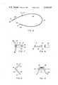
- FIG. 1is an exterior view of my surgical tape device.
- FIG. 2is a broken enlarged cross sectional view of the surgical tape device of FIG. 1.
- FIG. 3is a view of a portion of the surgical tape device of FIG. 1 in position to close off a blood vessel shown in cross section.
- FIG. 4is an exterior view of another embodiment of my surgical tape device having a curved needle end portion.
- FIG. 5is an enlarged cross sectional view of the surgical tape device of FIG. 4 showing the needle and the attachment of the tubular body portion to the needle.
- FIG. 6is an exterior view of another embodiment of my surgical tape device having a clamping pad.
- FIG. 7is another view of a portion of the surgical tape device of FIG. 6 showing the clamping pad.
- FIG. 8is an exploded view of the clamping pad portion of the surgical tape device of FIG. 6 showing the relation between the jaw portion and the tubular sleeve portion of the clamping pad.
- FIG. 9is a detailed view of the jaw portion of the clamping pad of the surgical tape device of FIG. 6 in open disassembled position.
- FIG. 10is a view of the surgical tape device of FIG. 6 in position to ligate a blood vessel shown in cross section.
- the surgical tape 10has a tubular body 11 which is composed of an elastomeric material, preferably silicone elastomer because of the compatibility of this material with body tissue.
- a tubular body 11which is composed of an elastomeric material, preferably silicone elastomer because of the compatibility of this material with body tissue.
- Various radiopaque substancessuch as barium compounds may be added to the elastomer so that the tape 10 will be visible on X-ray pictures.
- the tubular body 11has a substantially open lumen 11a which is unobstructed between the two ends 12 of the tubular body and which has air at substantially normal atmospheric pressure therein.
- the ends 12 of the tubular bodyare sealed with a fluid-tight seal 13 to prevent the air within the lumen 11a from escaping, with the sealing preferably being accomplished by filling the lumen 11a for a small distance from the ends 12 with a solid elastomeric material such as the elastomer of which the tubular body itself is composed.
- a preferred manner of sealing the ends of a tubular body composed of silicone elastomeris to slightly compress a portion of the tubular body, dip the ends of the tubular body in liquid silicone elastomer, and release the tubular body to allow silicone elastomer to be drawn into the lumen 11a, with the silicone hardening and adhering to the tubular body upon curing, with the liquid silicone used preferably being of the type which self cures by reacting with moisture in the air. It is also desirable to color code the various tapes to allow the surgeon to distinguish between the tapes he is using and thus the solid material which seals the lumen 11a of the tape may also be provided as a coating 13a to a portion of the exterior of the tubular body at the ends thereof as shown in FIG. 2, and this coating may be colored with a selected coloring material.
- the tapewill resist twisting when it is pulled around an artery, vein or other body structure and will tend to roll along such body vessels.
- the air cushion tape 10will tend to fully engage a blood vessel 14 as the tape is drawn tight, but will resist collapsing such that the inner surface of the lumen 11a would come into contact and rub against itself.
- the air cushion within the lumenis actually enhanced when the tubular body is compressed by surgical instruments or by hand, since such compression increases the air pressure inside the lumen above atmospheric pressure.
- the tape 10can roll along a blood vessel, thereby minimizing a major source of trauma to the blood vessel associated with ordinary flat tapes or nonair cushioned elastic tapes.
- the diameter of the interior lumen 11abe a substantial portion of the diameter of the tubular body 11 to allow the tubular body to compress and stretch easily when in contact with delicate body structures.
- a lumen diameter approximately one half or more of the tubular body outside diameterprovides preferred qualities of compressibility and stretch. Because the air cushion tape is utilized with relatively small body structures, the maximum useful outside diameter of the tubular body would be in the range of 150 thousandths of an inch, with such large tape devices being used for ligating only the largest arteries. Larger diameter devices are not desirable since the relatively small body structures could not be fully engaged, and the danger of the tubular body folding and pinching a blood vessel is increased.
- the tape device 15has a tubular body portion 16 having an interior lumen 16a, which is comprised of an elastomeric material, preferably a silicone elastomer.
- the preferred dimensions of the tubular body 16are the same as described above for the tubular body 11 of the surgical tape 10.
- One end 17 of the surgical tape device 15has a fluid tight seal 18 of elastomeric material formed in the manner described above for the air cushion tape 10.
- the sealing material of the seal 18 which is applied to the end of the tapemay also be applied as a coating 18a to the exterior of the tape, as shown in FIG. 4, with a coloring material added thereto to allow color coding of the tape.
- the other end 19 of the tape 15has a needle portion 20 affixed thereto.
- the needle portion 20 and its attachment to the body 16 of the tape device 15is best shown in the cross sectional view of FIG. 5.
- the needle 20has a hollow tube portion 21 into which the end portion of the tubular body 16 extends.
- the interior of the lumen of the tube portion 21is preferably of smaller diameter than the exterior diameter of the elastomeric tubular body 16, thus requiring that the tubular body 16 be compressed within the hollow tube portion 21.
- An air cushion at substantially atmospheric pressureis provided within the tape 15 by providing a fluid tight seal 22 at the end 19 which is composed of a sealing material such as silicone elastomer.
- the seal 22 of silicone elastomermay be applied to the end of the tape 15 in a liquid state, with the elastomer curing to a solid state in a manner similar to that described above for the surgical tape device 10.
- the needle 20has a pointed end 23 which is provided to enable the needle to be passed through soft body material or between separate adjacent body tissues. It is preferred that the needle 20 not have a cutting edge so as to reduce the possibility of inadvertently puncturing or penetrating body tissues.
- the curved needle 20 shown in FIG. 5is preferably formed from a straight piece of hollow metal tubing such as stainless steel tubing, with the elastomeric tubular body portion 16 being drawn into the hollow interior of the tubing.
- the end 19 of the elastomeric tubular bodythen has the seal 22 formed thereon by application of the liquid sealing material as described above.
- the seal 22should extend within the tubular body 16 such that when the hollow metal tubing is curved as described below, the silicone elastomer seal 22 within the tubular body portion 16 will also be curved to affix the tubular body within the hollow needle.
- the free end of the straight metal tubeis then swaged to form the point 23.
- This constructionis preferred since it provides an unobstructed connection of the needle to the tubular body, and a smooth needle with an unobstructed exterior.
- the needleis preferably curved as is customary with surgical needles.
- the curved needle 20allows the surgical tape device 15 to be pulled around organs and through tight spaces which would otherwise be difficult to reach, while the air entrapped in the interior lumen 16a of the tubular body inhibits the tape from folding or twisting, and thereby tends to prevent injury to blood vessels, ducts or other body structures around which it is pulled or engaged for ligation.
- a further embodiment of a surgical tape device especially adapted for temporarily and quickly ligating blood vesselsis shown generally at 25 in FIG. 6.
- the surgical tape device 25has a tubular body 26 made of an elastomeric material such as silicone elastomer, and is preferably plugged and sealed at each of the two ends 27 thereof with a seal 28 in a manner similar to that described above for the air cushion tape 10 to entrap air at substantially atmospheric pressure therein, although the surgical tape device 25 may satisfactorily employ a non-air cushioned hollow elongate elastomeric body or a solid elongate elastomeric body for some applications.
- the sealing of the ends 27is preferred since this construction provides the same air cushioning advantages for the tape device 25 as are described above for the tape device 10.
- a colored elastomeric coating 28amay be applied to a portion of the exterior of the tubular body 26 at the ends thereof to provide color coding.
- the surgical tape device 25has a clamping pad 30 attached to the tubular body at a point intermediate the ends thereof.
- a blood vessel or other ductmay be quickly and releasably closed or partially occluded between the tubular body 26 and the pad 30, as described more fully below.
- tubular body portion 26is preferably passed up through an opening 31 in a clamping jaw portion 32 of the pad 30 and may be wound around the outside of the pad and back through the opening 31 to prevent the pad 30 from sliding along the tubular body 26.
- the padmay alternatively be glued or otherwise affixed to the tubular body as desired.
- a sleeve 33is fitted tightly over the clamping jaw 32.
- the clamping jawis preferably made of a stiff but resilient plastic material, whereas the sleeve 33 is preferably made of a softer elastomeric material, and may be transparent as illustrated in FIG. 7.
- the clamping jaw portion 32 and the sleeve portion 33are shown in disassembled relation in FIG. 8.
- the clamping jaw portion 32has a substantially straight first jaw member 34 and a similar second jaw member 35 attached together by a thinner and more easily bendable resilient hinge portion 36 formed integrally with the jaw members.
- the clamping jaw 32is preferably composed of a stiff but resilient material such as nylon or polyethylene which will bend slightly to allow the tubular body portion to slip between the jaw members 34 and 35.
- the sleeve 33does not cover the entire length of the clamping jaw, but leaves uncovered the end of the clamping jaw opposite the end at which it is attached to the tubular body so that the tubular body may be engaged with and restrained between the jaw members 34 and 35.
- the ends of the jaw members 34 and 35are preferably beveled as shown to assist in guiding the tubular body so that it may be more easily inserted between the jaw members and releasably held therebetween.
- the preferred construction of the clamping jawis shown in FIG. 9, wherein the clamping jaw is in an opened position.
- An integrally formed ridge 37extends along the inner edge of the first jaw member 34 for part of the length of the first jaw member, with this ridge 37 fitting into a mating groove 38 on the inner side of the second jaw member 35.
- the sleeve 33preferably consists of a hollow tube-like structure of resilient material which has an inside lumen having a diameter somewhat less than the outside dimensions of the clamping jaw when it is in its closed position.
- the sleeve 33must be expanded to allow it to slip over the clamping jaw 32, and thus the resilient sleeve tends to hold the clamping jaw 32 in its closed position with the jaw members 34 and 35 in engagement.
- FIG. 10shows the device partially ligating a blood vessel 38 which is shown in cross section.
- the surgeonplaces the sleeve 33 of the pad 30 against the vessel 38 which is to be occluded, and then draws the tubular body 26 of the surgical tape device around the blood vessel.
- the tubular bodyis brought into contact with the jaw portion 32 and is pulled into and between the jaw members 34 and 35 so that the jaw portion will firmly engage and releasably hold the tubular body.
- the extent to which the blood vessel 38 is closed offis determined by the amount of pressure applied between the tubular body 26 and the sleeve 33 of the pad.
- This pressuremay be increased by drawing the elastic tubular body 26 more tightly across the vessel 38 and pulling it between the jaw members 34 and 35 to hold it therebetween at a greater tension.
- the surgeonmay easily release the blood vessel 38 from its closure between the tubular body 26 and the pad 33 by pulling outwardly on the free portion 26a of the tubular body to pull it out of engagement with the jaw portion 32 and thus release the pressure on the blood vessel.
- the tubular body 26is formed of an elastomeric material, the pressure on the vessel 38 can be controlled, since high pressures within an artery, for example, will expand the artery under the force of the elastomeric tubular body 26 and allow some blood to pass therethrough.
- a cathetermay be passed through an artery closed off by the tape devices to blood flow, but which can expand under further pressure to allow the catheter to pass.
- an air cushioned tubular body 25With the use of an air cushioned tubular body 25, the possibility of the tubular body twisting or folding against the blood vessel, with resulting injury to the vessel, is minimized.
Landscapes
- Health & Medical Sciences (AREA)
- Surgery (AREA)
- Life Sciences & Earth Sciences (AREA)
- Heart & Thoracic Surgery (AREA)
- Animal Behavior & Ethology (AREA)
- Veterinary Medicine (AREA)
- Public Health (AREA)
- General Health & Medical Sciences (AREA)
- Biomedical Technology (AREA)
- Medical Informatics (AREA)
- Molecular Biology (AREA)
- Nuclear Medicine, Radiotherapy & Molecular Imaging (AREA)
- Engineering & Computer Science (AREA)
- Vascular Medicine (AREA)
- Reproductive Health (AREA)
- Epidemiology (AREA)
- Media Introduction/Drainage Providing Device (AREA)
Abstract
Description
1. Field of the Invention
This invention pertains generally to the field of surgical appliances and instruments, and more particularly to surgical tape utilized to restrain, hold, or partially or fully ligate body structures.
2. Description of the Prior Art
It is commonly necessary during surgical procedures to manipulate organs and other structures within the operating area, and to hold these structures away from the area where the surgeon is working. This necessary restraint and manipulation of body organs and structures is often accomplished by passing a string-like material under the organ and pulling on the string to hold back the organ. It is apparent that such procedures must be accomplished with minimal trauma to the body organs being manipulated.
It is also a common surgical procedure to ligate tubular body structures such as blood vessels and organ ducts to prevent flow therethrough during the surgical procedures. Such ligations are commonly accomplished by applying tension to the vessel with a non-elastic suture material where the use of a hemostat is not necessary or desirable. Such tension and pulling on body structures by non-elastic materials and the like is often accompanied by damage to the rather fragile tissue structures. Substantially flat solid elastic tapes have been used in place of the non-elastic tapes, but if such tapes are twisted or not oriented properly; they may tend to dig into body tissues. Hollow open elastic tapes have also been utilized, but such hollow tapes will not easily roll when pulled along body structures and may twist in use, thereby presenting the possibility of injury to delicate body tissues.
I have invented a surgical tape device which can be utilized to ligate or apply pressure to blood vessels, organ ducts or other body structures with minimal trauma to the body tissues involved. My surgical tape device has an elongated tubular body composed of an elastomeric material which is preferably silicone elastomer. The elastomeric quality of the tubular body provides the highly desirable advantage of allowing the tubular body to yield when in contact with body tissues, thus controlling the amount of pressure that is applied to the tissues or the pressure by which body structures such as blood vessels and organ ducts are shut off.
The hollow tube provides a lumen therein which enhances the elastic qualities of my tape and provides for greater "give" when the tape is in contact with the body structure. The ends of the tubular body of my invention may be sealed with sealing means such as silicone elastomer which is preferably applied in a liquid state thereto within the lumen, and which is self curing to a solid state adhering to the walls of the lumen. Because the ends of the tape are sealed to entrap air at substantially atmospheric pressure within the lumen, my surgical tape will resist collapsing when in contact with a body structure, a common and undesirable occurence with ordinary hollow elastic tubing. The collapsing of ordinary hollow tape brings the interior wall of the tape into rubbing contact with itself, allowing such tape to easily twist and inhibiting rolling of the tape when pulled along a blood vessel or the like. The sealed tubular body of my invention prevents the inside surface of the lumen from easily coming into contact with itself and greatly reduces twisting of the tape. When the sealed tubular body is compressed by a surgical instrument or by hand, the pressure in the lumen is actually increased above atmospheric pressure, which inhibits collapsing of the tubular body and facilitates rolling of the body along a blood vessel. For convenience, the ends of the tape may be color coded by coating them with an elastomeric material compatible with that of which the tubular body is composed, and which has a selected color impregnated therein.
In a modification of the surgical tape device of my invention, a needle without a cutting edge is affixed to one of the sealed ends of the tubular body, with a portion of the end of the tubular body extending into the hollow interior of the metal needle, which is preferably curved. The tubular body is sealed and affixed to the interior of the needle, with no obstructions being present on the exterior of the needle or of the tubular body which could interfere with passage of the needle and tubular body through various body tissues.
A further embodiment of my surgical tape device employs a clamping pad attached to the tubular body at a point intermediate the ends thereof. The clamping pad is attached at one end thereof to the tubular body and has a jaw portion at the other end thereof. A blood vessel or organ duct may be easily and quickly ligated with a desired amount of pressure by simply holding the blood vessel between the clamping pad and one of the free portions of the tubular body portion, drawing the tubular body over the blood vessel so as to hold the blood vessel between the tubular body and the pad, and then drawing the tubular body into the jaws of the clamping pad to securely and releasably hold it therein. The amount of pressure applied to the blood vessel can be adjusted by pulling the tubular body through the jaws of the clamping pad to a greater or lesser degree. The pressure on the blood vessel can thus be controlled, as desired, to prevent any blood from passing through the vessel or to close the blood vessel only partially. The clamping pad can thus be utilized in such applications as arterial catheterization to prevent flow of blood but to allow a catheter to be passed up an artery which has pressure applied to it by the clamping pad and tubular body.
Further objects, features and advantages of my invention will be apparent from the following detailed description taken in conjunction with the accompanying drawings showing preferred embodiments of a surgical tape device exemplifying the principles of my invention.
In the drawings:
FIG. 1 is an exterior view of my surgical tape device.
FIG. 2 is a broken enlarged cross sectional view of the surgical tape device of FIG. 1.
FIG. 3 is a view of a portion of the surgical tape device of FIG. 1 in position to close off a blood vessel shown in cross section.
FIG. 4 is an exterior view of another embodiment of my surgical tape device having a curved needle end portion.
FIG. 5 is an enlarged cross sectional view of the surgical tape device of FIG. 4 showing the needle and the attachment of the tubular body portion to the needle.
FIG. 6 is an exterior view of another embodiment of my surgical tape device having a clamping pad.
FIG. 7 is another view of a portion of the surgical tape device of FIG. 6 showing the clamping pad.
FIG. 8 is an exploded view of the clamping pad portion of the surgical tape device of FIG. 6 showing the relation between the jaw portion and the tubular sleeve portion of the clamping pad.
FIG. 9 is a detailed view of the jaw portion of the clamping pad of the surgical tape device of FIG. 6 in open disassembled position.
FIG. 10 is a view of the surgical tape device of FIG. 6 in position to ligate a blood vessel shown in cross section.
Referring now more particularly to the drawings, wherein like numerals refer to like parts throughout the several views, a preferred embodiment of a surgical tape device in accordance with my invention is shown generally at 10 in FIG. 1. Thesurgical tape 10 has a tubular body 11 which is composed of an elastomeric material, preferably silicone elastomer because of the compatibility of this material with body tissue. Various radiopaque substances such as barium compounds may be added to the elastomer so that thetape 10 will be visible on X-ray pictures. As best shown in the cross sectional view in FIG. 2, the tubular body 11 has a substantially open lumen 11a which is unobstructed between the twoends 12 of the tubular body and which has air at substantially normal atmospheric pressure therein. Theends 12 of the tubular body are sealed with a fluid-tight seal 13 to prevent the air within the lumen 11a from escaping, with the sealing preferably being accomplished by filling the lumen 11a for a small distance from theends 12 with a solid elastomeric material such as the elastomer of which the tubular body itself is composed. A preferred manner of sealing the ends of a tubular body composed of silicone elastomer is to slightly compress a portion of the tubular body, dip the ends of the tubular body in liquid silicone elastomer, and release the tubular body to allow silicone elastomer to be drawn into the lumen 11a, with the silicone hardening and adhering to the tubular body upon curing, with the liquid silicone used preferably being of the type which self cures by reacting with moisture in the air. It is also desirable to color code the various tapes to allow the surgeon to distinguish between the tapes he is using and thus the solid material which seals the lumen 11a of the tape may also be provided as acoating 13a to a portion of the exterior of the tubular body at the ends thereof as shown in FIG. 2, and this coating may be colored with a selected coloring material.
Because theends 12 of theair cushion tape 10 are sealed, the tape will resist twisting when it is pulled around an artery, vein or other body structure and will tend to roll along such body vessels. As best shown in FIG. 3, theair cushion tape 10 will tend to fully engage ablood vessel 14 as the tape is drawn tight, but will resist collapsing such that the inner surface of the lumen 11a would come into contact and rub against itself. The air cushion within the lumen is actually enhanced when the tubular body is compressed by surgical instruments or by hand, since such compression increases the air pressure inside the lumen above atmospheric pressure. Because the air cushion within the lumen of thetape 10 inhibits the opposite sides of the inner surface of the lumen 11a from coming into contact with each other, thetape 10 can roll along a blood vessel, thereby minimizing a major source of trauma to the blood vessel associated with ordinary flat tapes or nonair cushioned elastic tapes.
It is preferred that the diameter of the interior lumen 11a be a substantial portion of the diameter of the tubular body 11 to allow the tubular body to compress and stretch easily when in contact with delicate body structures. A lumen diameter approximately one half or more of the tubular body outside diameter provides preferred qualities of compressibility and stretch. Because the air cushion tape is utilized with relatively small body structures, the maximum useful outside diameter of the tubular body would be in the range of 150 thousandths of an inch, with such large tape devices being used for ligating only the largest arteries. Larger diameter devices are not desirable since the relatively small body structures could not be fully engaged, and the danger of the tubular body folding and pinching a blood vessel is increased.
Another embodiment of my surgical tape device is shown generally at 15 in FIG. 4. Thetape device 15 has atubular body portion 16 having aninterior lumen 16a, which is comprised of an elastomeric material, preferably a silicone elastomer. The preferred dimensions of thetubular body 16 are the same as described above for the tubular body 11 of thesurgical tape 10. Oneend 17 of thesurgical tape device 15 has a fluidtight seal 18 of elastomeric material formed in the manner described above for theair cushion tape 10. The sealing material of theseal 18 which is applied to the end of the tape may also be applied as acoating 18a to the exterior of the tape, as shown in FIG. 4, with a coloring material added thereto to allow color coding of the tape. Theother end 19 of thetape 15 has aneedle portion 20 affixed thereto.
Theneedle portion 20 and its attachment to thebody 16 of thetape device 15 is best shown in the cross sectional view of FIG. 5. Theneedle 20 has ahollow tube portion 21 into which the end portion of thetubular body 16 extends. As shown in FIG. 5, the interior of the lumen of thetube portion 21 is preferably of smaller diameter than the exterior diameter of the elastomerictubular body 16, thus requiring that thetubular body 16 be compressed within thehollow tube portion 21. An air cushion at substantially atmospheric pressure is provided within thetape 15 by providing a fluidtight seal 22 at theend 19 which is composed of a sealing material such as silicone elastomer. Theseal 22 of silicone elastomer may be applied to the end of thetape 15 in a liquid state, with the elastomer curing to a solid state in a manner similar to that described above for thesurgical tape device 10. Theneedle 20 has apointed end 23 which is provided to enable the needle to be passed through soft body material or between separate adjacent body tissues. It is preferred that theneedle 20 not have a cutting edge so as to reduce the possibility of inadvertently puncturing or penetrating body tissues. Thecurved needle 20 shown in FIG. 5 is preferably formed from a straight piece of hollow metal tubing such as stainless steel tubing, with the elastomerictubular body portion 16 being drawn into the hollow interior of the tubing. Theend 19 of the elastomeric tubular body then has theseal 22 formed thereon by application of the liquid sealing material as described above. As best shown in FIG. 5, theseal 22 should extend within thetubular body 16 such that when the hollow metal tubing is curved as described below, thesilicone elastomer seal 22 within thetubular body portion 16 will also be curved to affix the tubular body within the hollow needle. The free end of the straight metal tube is then swaged to form thepoint 23. This construction is preferred since it provides an unobstructed connection of the needle to the tubular body, and a smooth needle with an unobstructed exterior. The needle is preferably curved as is customary with surgical needles. Thecurved needle 20 allows thesurgical tape device 15 to be pulled around organs and through tight spaces which would otherwise be difficult to reach, while the air entrapped in theinterior lumen 16a of the tubular body inhibits the tape from folding or twisting, and thereby tends to prevent injury to blood vessels, ducts or other body structures around which it is pulled or engaged for ligation.
A further embodiment of a surgical tape device especially adapted for temporarily and quickly ligating blood vessels is shown generally at 25 in FIG. 6. Thesurgical tape device 25 has atubular body 26 made of an elastomeric material such as silicone elastomer, and is preferably plugged and sealed at each of the two ends 27 thereof with aseal 28 in a manner similar to that described above for theair cushion tape 10 to entrap air at substantially atmospheric pressure therein, although thesurgical tape device 25 may satisfactorily employ a non-air cushioned hollow elongate elastomeric body or a solid elongate elastomeric body for some applications. The sealing of theends 27 is preferred since this construction provides the same air cushioning advantages for thetape device 25 as are described above for thetape device 10. A coloredelastomeric coating 28a may be applied to a portion of the exterior of thetubular body 26 at the ends thereof to provide color coding. Thesurgical tape device 25 has aclamping pad 30 attached to the tubular body at a point intermediate the ends thereof. A blood vessel or other duct may be quickly and releasably closed or partially occluded between thetubular body 26 and thepad 30, as described more fully below.
The attachment of thetubular body portion 26 to thepad 30 is best shown in FIG. 7. As shown therein, thetubular body 26 is preferably passed up through anopening 31 in aclamping jaw portion 32 of thepad 30 and may be wound around the outside of the pad and back through theopening 31 to prevent thepad 30 from sliding along thetubular body 26. The pad may alternatively be glued or otherwise affixed to the tubular body as desired.
Asleeve 33 is fitted tightly over the clampingjaw 32. The clamping jaw is preferably made of a stiff but resilient plastic material, whereas thesleeve 33 is preferably made of a softer elastomeric material, and may be transparent as illustrated in FIG. 7. The clampingjaw portion 32 and thesleeve portion 33 are shown in disassembled relation in FIG. 8. The clampingjaw portion 32 has a substantially straightfirst jaw member 34 and a similarsecond jaw member 35 attached together by a thinner and more easily bendableresilient hinge portion 36 formed integrally with the jaw members.
The clampingjaw 32 is preferably composed of a stiff but resilient material such as nylon or polyethylene which will bend slightly to allow the tubular body portion to slip between thejaw members sleeve 33 does not cover the entire length of the clamping jaw, but leaves uncovered the end of the clamping jaw opposite the end at which it is attached to the tubular body so that the tubular body may be engaged with and restrained between thejaw members jaw members ridge 37 extends along the inner edge of thefirst jaw member 34 for part of the length of the first jaw member, with thisridge 37 fitting into amating groove 38 on the inner side of thesecond jaw member 35. The interaction of theridge 37 with the groove on the inner surface of the second jaw member, when the clamping jaw is in its closed position as shown in FIG. 8, prevents thejaw members
Thesleeve 33 preferably consists of a hollow tube-like structure of resilient material which has an inside lumen having a diameter somewhat less than the outside dimensions of the clamping jaw when it is in its closed position. Thesleeve 33 must be expanded to allow it to slip over the clampingjaw 32, and thus the resilient sleeve tends to hold the clampingjaw 32 in its closed position with thejaw members
The use of thesurgical tape device 25 withclamping pad 30 is best illustrated with reference to FIG. 10, which shows the device partially ligating ablood vessel 38 which is shown in cross section. The surgeon places thesleeve 33 of thepad 30 against thevessel 38 which is to be occluded, and then draws thetubular body 26 of the surgical tape device around the blood vessel. The tubular body is brought into contact with thejaw portion 32 and is pulled into and between thejaw members blood vessel 38 is closed off is determined by the amount of pressure applied between thetubular body 26 and thesleeve 33 of the pad. This pressure may be increased by drawing the elastictubular body 26 more tightly across thevessel 38 and pulling it between thejaw members blood vessel 38 from its closure between thetubular body 26 and thepad 33 by pulling outwardly on thefree portion 26a of the tubular body to pull it out of engagement with thejaw portion 32 and thus release the pressure on the blood vessel. Because thetubular body 26 is formed of an elastomeric material, the pressure on thevessel 38 can be controlled, since high pressures within an artery, for example, will expand the artery under the force of the elastomerictubular body 26 and allow some blood to pass therethrough. Furthermore, a catheter may be passed through an artery closed off by the tape devices to blood flow, but which can expand under further pressure to allow the catheter to pass. With the use of an air cushionedtubular body 25, the possibility of the tubular body twisting or folding against the blood vessel, with resulting injury to the vessel, is minimized.
It is understood that my invention is not confined to the particular construction and arrangement of parts herein illustrated and described, but embraces all such modified forms thereof as may come within the scope of the following claims.
Claims (9)
1. A surgical tape device, comprising:
(a) an elongated tubular body composed of a silicone elastomeric material having a lumen therein and an exterior diameter of less than about 150 thousandths of an inch, and having two ends;
(b) a fluid-tight seal of silicone elastomeric material filling each of the ends of said tubular body to entrap air within said lumen at substantially atmospheric pressure;
(c) a hollow curved needle having an interior of smaller diameter than the normal exterior diameter of said tubular body, said hollow curved needle being securely attached to said tubular body at one end thereof by engagement of the end of said tubular body within a substantial length of a curved portion of the hollow interior of said needle whereby the elastomeric seal which fills the end of the tubular body is curved by conformity of the tubular body to the curved portion of the needle to affix the tubular body within the needle, said needle having a point formed on the end thereof.
2. The surgical tape device as specified in claim 1 including a coating of silicone elastomeric material on a portion of the exterior of said tubular body at the end thereof which is opposite to the end having said needle affixed thereon, said elastomeric material being of a selected color to thereby provide color coding of the surgical tape device.
3. A surgical tape device, comprising:
(a) an elongated body composed of an elastomeric material and having two ends; and
(b) a clamping pad attached to said elongated body at a point intermediate the ends thereof, said clamping pad having a jaw portion and an elongated elastomeric sleeve which fits over and resiliently holds said jaw portion, said jaw portion being formed of stiff but resilient material having first and second jaw members attached together by a resilient hinge portion formed integrally therewith, said sleeve member fitting over and restrainably holding said first and second jaw members in engagement over a portion of the length of said jaw members, a portion of the length of said jaw members being unobstructed to allow insertion of said elongated body between said first and second jaw members to restrainably engage and releasably hold said elongated body, whereby a body vessel may be emplaced between said elastomeric sleeve and a portion of said elongated body intermediate the point of its attachment to said clamping pad and the point of its engagement between said jaw members to apply pressure to said body vessel which may be adjusted by the position at which said elongated body is drawn into said jaw members of said pad.
4. The surgical tape device as specified in claim 3 wherein said elongated body is tubular and has a lumen therein, and including a fluid-tight seal of elastomeric material filling each end of said elongated tubular body to entrap air within said lumen at substantially atmospheric pressure.
5. The surgical tape device as specified in claim 4 wherein said elongated body and fluid-tight seal are composed of silicone elastomer.
6. The surgical tape device as specified in claim 3 including a coating of elastomeric material on a portion of the exterior of said elongated body at the ends thereof, said elastomeric material being of a selected color to thereby provide color coding of the surgical tape device.
7. The surgical tape device as specified in claim 3 including a hollow tubular curved metal needle affixed to said elongated body at one end thereof, said one end of said elongated body extending into the hollow interior of said needle, said needle having a point formed on the end thereof.
8. The surgical tape device as specified in claim 3 wherein the outside diameter of said elongated body is less than 150 thousandths of an inch.
9. The surgical tape device specified in claim 3 wherein said first jaw member has a longitudinal ridge extending along the surface thereof which engages said second jaw member, and wherein said second jaw member has a groove which receives said longitudinal ridge in mating relation when said jaws are in engagement to prevent lateral slipping of the jaw members with respect to one another.
Priority Applications (1)
| Application Number | Priority Date | Filing Date | Title |
|---|---|---|---|
| US05/661,251US4140125A (en) | 1976-02-25 | 1976-02-25 | Surgical tape device |
Applications Claiming Priority (1)
| Application Number | Priority Date | Filing Date | Title |
|---|---|---|---|
| US05/661,251US4140125A (en) | 1976-02-25 | 1976-02-25 | Surgical tape device |
Publications (1)
| Publication Number | Publication Date |
|---|---|
| US4140125Atrue US4140125A (en) | 1979-02-20 |
Family
ID=24652810
Family Applications (1)
| Application Number | Title | Priority Date | Filing Date |
|---|---|---|---|
| US05/661,251Expired - LifetimeUS4140125A (en) | 1976-02-25 | 1976-02-25 | Surgical tape device |
Country Status (1)
| Country | Link |
|---|---|
| US (1) | US4140125A (en) |
Cited By (63)
| Publication number | Priority date | Publication date | Assignee | Title |
|---|---|---|---|---|
| US4359053A (en)* | 1980-06-05 | 1982-11-16 | Snyder Laboratories, Inc. | Means of fastening silicone tubing to a rigid surgical needle |
| US4392495A (en)* | 1981-08-31 | 1983-07-12 | Bayers Jon Herbert | Apparatus for and method of suturing tissue |
| JPS58188440A (en)* | 1982-04-15 | 1983-11-02 | エチコン・インコ−ポレ−テツド | Surgical staple coated with silicone |
| US4478219A (en)* | 1982-03-24 | 1984-10-23 | Manuel Dujovny | Temporary microvascular occluder |
| US4504269A (en)* | 1982-03-05 | 1985-03-12 | Durand Alain J | Device for catheterization in particular for perfusions in the medical and veterinary fields |
| US4708140A (en)* | 1986-05-08 | 1987-11-24 | Baron Howard C | Atraumatic vascular balloon clamp |
| US4805292A (en)* | 1986-06-12 | 1989-02-21 | Kabushiki Kaisha Mutec | Suturing needle with suture and method of producing the same |
| US4890614A (en)* | 1986-02-19 | 1990-01-02 | Yasuo Nakamura | Suture needle and its manufacturing process |
| US4976684A (en)* | 1988-11-21 | 1990-12-11 | Johnson & Johnson Orthopaedics, Inc. | Method of using a bendable trocar |
| EP0390481A3 (en)* | 1989-03-23 | 1991-09-11 | Sanyo Chemical Industries Ltd. | Surgical adhesive sheet |
| US5573529A (en)* | 1994-10-31 | 1996-11-12 | Haak; Benjamin A. | Color coded medical instruments |
| US20010018592A1 (en)* | 1999-03-01 | 2001-08-30 | Laurent Schaller | Bridge clip tissue connector apparatus and methods |
| US6296633B1 (en)* | 1998-01-09 | 2001-10-02 | Schneider (Usa) Inc. | Medical device tubing assembly and method of making the same |
| WO2001076487A1 (en)* | 2000-04-05 | 2001-10-18 | Coroneo, Inc. | Surgical suturing clamp |
| US6514265B2 (en) | 1999-03-01 | 2003-02-04 | Coalescent Surgical, Inc. | Tissue connector apparatus with cable release |
| US6551332B1 (en) | 2000-03-31 | 2003-04-22 | Coalescent Surgical, Inc. | Multiple bias surgical fastener |
| US20030078603A1 (en)* | 1999-03-01 | 2003-04-24 | Coalescent Surgical, Inc. | Tissue connector apparatus and methods |
| US6607541B1 (en) | 1998-06-03 | 2003-08-19 | Coalescent Surgical, Inc. | Tissue connector apparatus and methods |
| US20030183072A1 (en)* | 2000-11-02 | 2003-10-02 | Lopez Carlos Erviti | Vacuum brake booster |
| US6641593B1 (en) | 1998-06-03 | 2003-11-04 | Coalescent Surgical, Inc. | Tissue connector apparatus and methods |
| US20040068276A1 (en)* | 2002-10-04 | 2004-04-08 | Steve Golden | Anastomosis apparatus and methods |
| US20040098039A1 (en)* | 2002-01-09 | 2004-05-20 | Paul Sinding | Surgical tool |
| US20040111103A1 (en)* | 2002-12-03 | 2004-06-10 | Nixon Margaret Marie | Surgical tape tensioner |
| US20040111099A1 (en)* | 2000-10-10 | 2004-06-10 | Coalescent Surgical, Inc. | Minimally invasive valve repair procedure and apparatus |
| US20050021054A1 (en)* | 2003-07-25 | 2005-01-27 | Coalescent Surgical, Inc. | Sealing clip, delivery systems, and methods |
| US20050043749A1 (en)* | 2003-08-22 | 2005-02-24 | Coalescent Surgical, Inc. | Eversion apparatus and methods |
| US20050065601A1 (en)* | 2002-04-18 | 2005-03-24 | Coalescent Surgical, Inc. | Annuloplasty apparatus and methods |
| US20050070924A1 (en)* | 2003-09-26 | 2005-03-31 | Coalescent Surgical, Inc. | Surgical connection apparatus and methods |
| US20050075659A1 (en)* | 2003-03-30 | 2005-04-07 | Fidel Realyvasquez | Apparatus and methods for minimally invasive valve surgery |
| US6945980B2 (en) | 1998-06-03 | 2005-09-20 | Medtronic, Inc. | Multiple loop tissue connector apparatus and methods |
| US20060058574A1 (en)* | 1999-06-09 | 2006-03-16 | Jorg Priewe | Method and apparatus for adjusting flexible areal polymer implants |
| US20060229675A1 (en)* | 2005-04-07 | 2006-10-12 | Roberto Novoa | Anchoring System for Valve Replacement |
| US20060293701A1 (en)* | 2001-05-02 | 2006-12-28 | Medtronic, Inc. | Self-closing surgical clip for tissue |
| US20080249546A1 (en)* | 2007-01-05 | 2008-10-09 | Sandstrom Jeffrey D | Anastomosis systems and methods |
| US20090264903A1 (en)* | 2008-03-10 | 2009-10-22 | Medtronic, Inc. | Apparatus and methods for minimally invasive valve repair |
| US20100262167A1 (en)* | 2009-04-09 | 2010-10-14 | Medtronic, Inc. | Medical Clip with Radial Tines, System and Method of Using Same |
| US20100274267A1 (en)* | 2009-04-24 | 2010-10-28 | Medtronics, Inc. | Medical Clip with Tines, System and Method of Using Same |
| US7879047B2 (en) | 2003-12-10 | 2011-02-01 | Medtronic, Inc. | Surgical connection apparatus and methods |
| US7938840B2 (en) | 1999-04-05 | 2011-05-10 | Medtronic, Inc. | Apparatus and methods for anastomosis |
| US7976556B2 (en) | 2002-09-12 | 2011-07-12 | Medtronic, Inc. | Anastomosis apparatus and methods |
| EP2025294A3 (en)* | 2007-08-17 | 2012-02-08 | Ethicon GmbH | Vessel-loop and method of making same |
| US8529583B1 (en) | 1999-09-03 | 2013-09-10 | Medtronic, Inc. | Surgical clip removal apparatus |
| CN103393442A (en)* | 2013-08-06 | 2013-11-20 | 杨蓊勃 | Operation relaxation suture silica gel pipeline |
| US8968336B2 (en) | 2011-12-07 | 2015-03-03 | Edwards Lifesciences Corporation | Self-cinching surgical clips and delivery system |
| US9017347B2 (en) | 2011-12-22 | 2015-04-28 | Edwards Lifesciences Corporation | Suture clip deployment devices |
| US20150257932A1 (en)* | 2013-11-25 | 2015-09-17 | Innfocus, Inc. | Methods, Systems and Devices for Treating Glaucoma |
| CN105147348A (en)* | 2015-08-12 | 2015-12-16 | 四川大学华西第二医院 | Rapid uterus hemostat |
| US9498202B2 (en) | 2012-07-10 | 2016-11-22 | Edwards Lifesciences Corporation | Suture securement devices |
| US9592048B2 (en) | 2013-07-11 | 2017-03-14 | Edwards Lifesciences Corporation | Knotless suture fastener installation system |
| US9592047B2 (en) | 2012-12-21 | 2017-03-14 | Edwards Lifesciences Corporation | System for securing sutures |
| US10016193B2 (en) | 2013-11-18 | 2018-07-10 | Edwards Lifesciences Ag | Multiple-firing crimp device and methods for using and manufacturing same |
| CN108567464A (en)* | 2017-06-29 | 2018-09-25 | 南阳市中心医院 | For interventional therapy operation femoral hemostasis device |
| US10136898B2 (en) | 2010-03-09 | 2018-11-27 | Teleflex Medical Incorporated | Narrow profile surgical ligation clip |
| US10188383B2 (en) | 2013-07-09 | 2019-01-29 | Edwards Lifesciences Corporation | Suture clip deployment devices |
| US10307166B2 (en) | 2011-09-15 | 2019-06-04 | Teleflex Medical Incorporated | Manual surgical ligation clip applier |
| US10470759B2 (en) | 2015-03-16 | 2019-11-12 | Edwards Lifesciences Corporation | Suture securement devices |
| US10624630B2 (en) | 2012-07-10 | 2020-04-21 | Edwards Lifesciences Ag | Multiple-firing securing device and methods for using and manufacturing same |
| US10786244B2 (en) | 2014-05-30 | 2020-09-29 | Edwards Lifesciences Corporation | Systems for securing sutures |
| US10863980B2 (en) | 2016-12-28 | 2020-12-15 | Edwards Lifesciences Corporation | Suture fastener having spaced-apart layers |
| USD912251S1 (en) | 2019-08-13 | 2021-03-02 | Ethicon, Inc. | Suture needle having a wave shape |
| USD912819S1 (en) | 2019-08-13 | 2021-03-09 | Ethicon, Inc. | Suture needle having a rotatable joint |
| US10939905B2 (en) | 2016-08-26 | 2021-03-09 | Edwards Lifesciences Corporation | Suture clips, deployment devices therefor, and methods of use |
| US11234691B2 (en) | 2019-08-13 | 2022-02-01 | Ethicon, Inc. | Composite suture needles having rotatable sections |
Citations (14)
| Publication number | Priority date | Publication date | Assignee | Title |
|---|---|---|---|---|
| US269468A (en)* | 1882-12-19 | Crayon and eraser holder | ||
| US1044302A (en)* | 1911-06-03 | 1912-11-12 | William M Underhill | Holder for cows' tails. |
| US1689889A (en)* | 1927-02-24 | 1928-10-30 | Nunes Roland | Adjustable hose clamp for milking machines |
| US2581114A (en)* | 1950-04-13 | 1952-01-01 | Leroy J Larson | Surgical device |
| US2928395A (en)* | 1957-06-20 | 1960-03-15 | Ethicon Inc | Sutures |
| US2936759A (en)* | 1957-09-03 | 1960-05-17 | Joseph L Yuhas | Tourniquet |
| US3735765A (en)* | 1971-03-18 | 1973-05-29 | D Ichelson | Method of closing lacerations and clamp therefor |
| US3762418A (en)* | 1972-05-17 | 1973-10-02 | W Wasson | Surgical suture |
| US3875946A (en)* | 1974-02-27 | 1975-04-08 | Ethicon Inc | Controlled release suture |
| US3880166A (en)* | 1973-08-20 | 1975-04-29 | Thomas J Fogarty | Vessel occluder |
| US3892240A (en)* | 1974-03-21 | 1975-07-01 | Charles Lanier Park | Surgical needle apparatus |
| US3910280A (en)* | 1974-06-21 | 1975-10-07 | Sherwood Medical Ind Inc | Body member tourniquet |
| US3914801A (en)* | 1971-09-14 | 1975-10-28 | Hair Again Ltd | Method of applying hair |
| US3993076A (en)* | 1973-08-20 | 1976-11-23 | Fogarty Thomas J | Vessel occluding instrument |
- 1976
- 1976-02-25USUS05/661,251patent/US4140125A/ennot_activeExpired - Lifetime
Patent Citations (14)
| Publication number | Priority date | Publication date | Assignee | Title |
|---|---|---|---|---|
| US269468A (en)* | 1882-12-19 | Crayon and eraser holder | ||
| US1044302A (en)* | 1911-06-03 | 1912-11-12 | William M Underhill | Holder for cows' tails. |
| US1689889A (en)* | 1927-02-24 | 1928-10-30 | Nunes Roland | Adjustable hose clamp for milking machines |
| US2581114A (en)* | 1950-04-13 | 1952-01-01 | Leroy J Larson | Surgical device |
| US2928395A (en)* | 1957-06-20 | 1960-03-15 | Ethicon Inc | Sutures |
| US2936759A (en)* | 1957-09-03 | 1960-05-17 | Joseph L Yuhas | Tourniquet |
| US3735765A (en)* | 1971-03-18 | 1973-05-29 | D Ichelson | Method of closing lacerations and clamp therefor |
| US3914801A (en)* | 1971-09-14 | 1975-10-28 | Hair Again Ltd | Method of applying hair |
| US3762418A (en)* | 1972-05-17 | 1973-10-02 | W Wasson | Surgical suture |
| US3880166A (en)* | 1973-08-20 | 1975-04-29 | Thomas J Fogarty | Vessel occluder |
| US3993076A (en)* | 1973-08-20 | 1976-11-23 | Fogarty Thomas J | Vessel occluding instrument |
| US3875946A (en)* | 1974-02-27 | 1975-04-08 | Ethicon Inc | Controlled release suture |
| US3892240A (en)* | 1974-03-21 | 1975-07-01 | Charles Lanier Park | Surgical needle apparatus |
| US3910280A (en)* | 1974-06-21 | 1975-10-07 | Sherwood Medical Ind Inc | Body member tourniquet |
Cited By (134)
| Publication number | Priority date | Publication date | Assignee | Title |
|---|---|---|---|---|
| US4359053A (en)* | 1980-06-05 | 1982-11-16 | Snyder Laboratories, Inc. | Means of fastening silicone tubing to a rigid surgical needle |
| US4392495A (en)* | 1981-08-31 | 1983-07-12 | Bayers Jon Herbert | Apparatus for and method of suturing tissue |
| US4504269A (en)* | 1982-03-05 | 1985-03-12 | Durand Alain J | Device for catheterization in particular for perfusions in the medical and veterinary fields |
| US4478219A (en)* | 1982-03-24 | 1984-10-23 | Manuel Dujovny | Temporary microvascular occluder |
| JPS58188440A (en)* | 1982-04-15 | 1983-11-02 | エチコン・インコ−ポレ−テツド | Surgical staple coated with silicone |
| EP0092383A3 (en)* | 1982-04-15 | 1985-03-06 | Ethicon Inc. | Silicone coated surgical staple |
| US4890614A (en)* | 1986-02-19 | 1990-01-02 | Yasuo Nakamura | Suture needle and its manufacturing process |
| US4708140A (en)* | 1986-05-08 | 1987-11-24 | Baron Howard C | Atraumatic vascular balloon clamp |
| US4805292A (en)* | 1986-06-12 | 1989-02-21 | Kabushiki Kaisha Mutec | Suturing needle with suture and method of producing the same |
| US4976684A (en)* | 1988-11-21 | 1990-12-11 | Johnson & Johnson Orthopaedics, Inc. | Method of using a bendable trocar |
| EP0390481A3 (en)* | 1989-03-23 | 1991-09-11 | Sanyo Chemical Industries Ltd. | Surgical adhesive sheet |
| US5457141A (en)* | 1989-03-23 | 1995-10-10 | Sanyo Chemical Industries, Ltd. | Surgical adhesive sheet, surgical instruments and methods of using the same |
| US5573529A (en)* | 1994-10-31 | 1996-11-12 | Haak; Benjamin A. | Color coded medical instruments |
| US6296633B1 (en)* | 1998-01-09 | 2001-10-02 | Schneider (Usa) Inc. | Medical device tubing assembly and method of making the same |
| US7763040B2 (en) | 1998-06-03 | 2010-07-27 | Medtronic, Inc. | Tissue connector apparatus and methods |
| US7547313B2 (en) | 1998-06-03 | 2009-06-16 | Medtronic, Inc. | Tissue connector apparatus and methods |
| US7963973B2 (en) | 1998-06-03 | 2011-06-21 | Medtronic, Inc. | Multiple loop tissue connector apparatus and methods |
| US20070027461A1 (en)* | 1998-06-03 | 2007-02-01 | Barry Gardiner | Tissue connector apparatus and methods |
| US20030195531A1 (en)* | 1998-06-03 | 2003-10-16 | Barry Gardiner | Tissue connector apparatus and methods |
| US20060004389A1 (en)* | 1998-06-03 | 2006-01-05 | Medtronic, Inc. | Multiple loop tissue connector apparatus and methods |
| US6945980B2 (en) | 1998-06-03 | 2005-09-20 | Medtronic, Inc. | Multiple loop tissue connector apparatus and methods |
| US6607541B1 (en) | 1998-06-03 | 2003-08-19 | Coalescent Surgical, Inc. | Tissue connector apparatus and methods |
| US6641593B1 (en) | 1998-06-03 | 2003-11-04 | Coalescent Surgical, Inc. | Tissue connector apparatus and methods |
| US6960221B2 (en) | 1999-03-01 | 2005-11-01 | Medtronic, Inc. | Tissue connector apparatus with cable release |
| US20050075667A1 (en)* | 1999-03-01 | 2005-04-07 | Laurent Schaller | Tissue connector apparatus and methods |
| US6613059B2 (en) | 1999-03-01 | 2003-09-02 | Coalescent Surgical, Inc. | Tissue connector apparatus and methods |
| US20010018592A1 (en)* | 1999-03-01 | 2001-08-30 | Laurent Schaller | Bridge clip tissue connector apparatus and methods |
| US7722643B2 (en) | 1999-03-01 | 2010-05-25 | Medtronic, Inc. | Tissue connector apparatus and methods |
| US6514265B2 (en) | 1999-03-01 | 2003-02-04 | Coalescent Surgical, Inc. | Tissue connector apparatus with cable release |
| US20030078603A1 (en)* | 1999-03-01 | 2003-04-24 | Coalescent Surgical, Inc. | Tissue connector apparatus and methods |
| US8353921B2 (en) | 1999-03-01 | 2013-01-15 | Medtronic, Inc | Tissue connector apparatus and methods |
| US20030093118A1 (en)* | 1999-03-01 | 2003-05-15 | Coalescent Surgical, Inc. | Tissue connector apparatus with cable release |
| US7892255B2 (en) | 1999-03-01 | 2011-02-22 | Medtronic, Inc. | Tissue connector apparatus and methods |
| US8118822B2 (en) | 1999-03-01 | 2012-02-21 | Medtronic, Inc. | Bridge clip tissue connector apparatus and methods |
| US20110184442A1 (en)* | 1999-04-05 | 2011-07-28 | Medtronic, Inc. | Apparatus and Methods for Anastomosis |
| US8211131B2 (en) | 1999-04-05 | 2012-07-03 | Medtronic, Inc. | Apparatus and methods for anastomosis |
| US7938840B2 (en) | 1999-04-05 | 2011-05-10 | Medtronic, Inc. | Apparatus and methods for anastomosis |
| US20060058574A1 (en)* | 1999-06-09 | 2006-03-16 | Jorg Priewe | Method and apparatus for adjusting flexible areal polymer implants |
| US7547316B2 (en)* | 1999-06-09 | 2009-06-16 | Ethicon, Inc. | Method and apparatus for adjusting flexible areal polymer implants |
| US8529583B1 (en) | 1999-09-03 | 2013-09-10 | Medtronic, Inc. | Surgical clip removal apparatus |
| US7896892B2 (en) | 2000-03-31 | 2011-03-01 | Medtronic, Inc. | Multiple bias surgical fastener |
| US8353092B2 (en) | 2000-03-31 | 2013-01-15 | Medtronic, Inc. | Multiple bias surgical fastener |
| US6551332B1 (en) | 2000-03-31 | 2003-04-22 | Coalescent Surgical, Inc. | Multiple bias surgical fastener |
| US8454635B2 (en) | 2000-04-05 | 2013-06-04 | Coroneo, Inc. | Surgical suturing clamp |
| US20030093091A1 (en)* | 2000-04-05 | 2003-05-15 | Anthony Paolitto | Surgical suturing clamp |
| WO2001076487A1 (en)* | 2000-04-05 | 2001-10-18 | Coroneo, Inc. | Surgical suturing clamp |
| US7914544B2 (en) | 2000-10-10 | 2011-03-29 | Medtronic, Inc. | Minimally invasive valve repair procedure and apparatus |
| US20110213387A1 (en)* | 2000-10-10 | 2011-09-01 | Medtronic, Inc. | Minimally Invasive Valve Repair Procedure and Apparatus |
| US20040111099A1 (en)* | 2000-10-10 | 2004-06-10 | Coalescent Surgical, Inc. | Minimally invasive valve repair procedure and apparatus |
| US7744611B2 (en) | 2000-10-10 | 2010-06-29 | Medtronic, Inc. | Minimally invasive valve repair procedure and apparatus |
| US20050101975A1 (en)* | 2000-10-10 | 2005-05-12 | Medtronic, Inc. | Minimally invasive valve repair procedure and apparatus |
| US20030183072A1 (en)* | 2000-11-02 | 2003-10-02 | Lopez Carlos Erviti | Vacuum brake booster |
| US20060293701A1 (en)* | 2001-05-02 | 2006-12-28 | Medtronic, Inc. | Self-closing surgical clip for tissue |
| US20040098039A1 (en)* | 2002-01-09 | 2004-05-20 | Paul Sinding | Surgical tool |
| US20050065601A1 (en)* | 2002-04-18 | 2005-03-24 | Coalescent Surgical, Inc. | Annuloplasty apparatus and methods |
| US8066724B2 (en) | 2002-09-12 | 2011-11-29 | Medtronic, Inc. | Anastomosis apparatus and methods |
| US7976556B2 (en) | 2002-09-12 | 2011-07-12 | Medtronic, Inc. | Anastomosis apparatus and methods |
| US20040068276A1 (en)* | 2002-10-04 | 2004-04-08 | Steve Golden | Anastomosis apparatus and methods |
| US8105345B2 (en) | 2002-10-04 | 2012-01-31 | Medtronic, Inc. | Anastomosis apparatus and methods |
| US8298251B2 (en) | 2002-10-04 | 2012-10-30 | Medtronic, Inc. | Anastomosis apparatus and methods |
| US20080154290A1 (en)* | 2002-10-04 | 2008-06-26 | Steve Golden | Anastomosis apparatus and methods |
| US20040111103A1 (en)* | 2002-12-03 | 2004-06-10 | Nixon Margaret Marie | Surgical tape tensioner |
| US20050075659A1 (en)* | 2003-03-30 | 2005-04-07 | Fidel Realyvasquez | Apparatus and methods for minimally invasive valve surgery |
| US20070142848A1 (en)* | 2003-07-25 | 2007-06-21 | Stephen Ainsworth | Sealing clip, delivery systems, and methods |
| US7182769B2 (en) | 2003-07-25 | 2007-02-27 | Medtronic, Inc. | Sealing clip, delivery systems, and methods |
| US20050021054A1 (en)* | 2003-07-25 | 2005-01-27 | Coalescent Surgical, Inc. | Sealing clip, delivery systems, and methods |
| US8211124B2 (en) | 2003-07-25 | 2012-07-03 | Medtronic, Inc. | Sealing clip, delivery systems, and methods |
| US20090240265A1 (en)* | 2003-08-22 | 2009-09-24 | Tom Breton | Eversion apparatus and methods |
| US8029519B2 (en) | 2003-08-22 | 2011-10-04 | Medtronic, Inc. | Eversion apparatus and methods |
| US20050043749A1 (en)* | 2003-08-22 | 2005-02-24 | Coalescent Surgical, Inc. | Eversion apparatus and methods |
| US8394114B2 (en) | 2003-09-26 | 2013-03-12 | Medtronic, Inc. | Surgical connection apparatus and methods |
| US20050070924A1 (en)* | 2003-09-26 | 2005-03-31 | Coalescent Surgical, Inc. | Surgical connection apparatus and methods |
| US7879047B2 (en) | 2003-12-10 | 2011-02-01 | Medtronic, Inc. | Surgical connection apparatus and methods |
| US20060229675A1 (en)* | 2005-04-07 | 2006-10-12 | Roberto Novoa | Anchoring System for Valve Replacement |
| US20080249546A1 (en)* | 2007-01-05 | 2008-10-09 | Sandstrom Jeffrey D | Anastomosis systems and methods |
| EP2025294A3 (en)* | 2007-08-17 | 2012-02-08 | Ethicon GmbH | Vessel-loop and method of making same |
| US8177836B2 (en) | 2008-03-10 | 2012-05-15 | Medtronic, Inc. | Apparatus and methods for minimally invasive valve repair |
| US20090264903A1 (en)* | 2008-03-10 | 2009-10-22 | Medtronic, Inc. | Apparatus and methods for minimally invasive valve repair |
| US8518060B2 (en) | 2009-04-09 | 2013-08-27 | Medtronic, Inc. | Medical clip with radial tines, system and method of using same |
| US20100262167A1 (en)* | 2009-04-09 | 2010-10-14 | Medtronic, Inc. | Medical Clip with Radial Tines, System and Method of Using Same |
| US20100274267A1 (en)* | 2009-04-24 | 2010-10-28 | Medtronics, Inc. | Medical Clip with Tines, System and Method of Using Same |
| US8668704B2 (en) | 2009-04-24 | 2014-03-11 | Medtronic, Inc. | Medical clip with tines, system and method of using same |
| US10136898B2 (en) | 2010-03-09 | 2018-11-27 | Teleflex Medical Incorporated | Narrow profile surgical ligation clip |
| US10307166B2 (en) | 2011-09-15 | 2019-06-04 | Teleflex Medical Incorporated | Manual surgical ligation clip applier |
| US10245037B2 (en) | 2011-12-07 | 2019-04-02 | Edwards Lifesciences Corporation | Self-cinching surgical clips and delivery system |
| US9668739B2 (en) | 2011-12-07 | 2017-06-06 | Edwards Lifesciences Corporation | Self-cinching surgical clips and delivery system |
| US11090053B2 (en) | 2011-12-07 | 2021-08-17 | Edwards Lifesciences Corporation | Methods of deploying self-cinching surgical clips |
| US11707280B2 (en) | 2011-12-07 | 2023-07-25 | Edwards Lifesciences Corporation | Methods of deploying self-cinching surgical clips |
| US8968336B2 (en) | 2011-12-07 | 2015-03-03 | Edwards Lifesciences Corporation | Self-cinching surgical clips and delivery system |
| US9017347B2 (en) | 2011-12-22 | 2015-04-28 | Edwards Lifesciences Corporation | Suture clip deployment devices |
| US9414837B2 (en) | 2011-12-22 | 2016-08-16 | Edwards Lifesciences Corporation | Suture clip deployment devices |
| US11185321B2 (en) | 2011-12-22 | 2021-11-30 | Edwards Lifesciences Corporation | Suture clip deployment devices |
| US10314573B2 (en) | 2011-12-22 | 2019-06-11 | Edwards Lifesciences Corporation | Suture clip deployment devices |
| US9549730B2 (en) | 2011-12-22 | 2017-01-24 | Edwards Lifesciences Corporation | Suture clip deployment devices |
| USRE47209E1 (en) | 2012-07-10 | 2019-01-22 | Edwards Lifesciences Corporation | Suture securement devices |
| US9498202B2 (en) | 2012-07-10 | 2016-11-22 | Edwards Lifesciences Corporation | Suture securement devices |
| US10624630B2 (en) | 2012-07-10 | 2020-04-21 | Edwards Lifesciences Ag | Multiple-firing securing device and methods for using and manufacturing same |
| US11382616B2 (en) | 2012-12-21 | 2022-07-12 | Edwards Lifesciences Corporation | Systems for securing sutures |
| US9592047B2 (en) | 2012-12-21 | 2017-03-14 | Edwards Lifesciences Corporation | System for securing sutures |
| US10441275B2 (en) | 2012-12-21 | 2019-10-15 | Edwards Lifesciences Corporation | Systems for securing sutures |
| US10188383B2 (en) | 2013-07-09 | 2019-01-29 | Edwards Lifesciences Corporation | Suture clip deployment devices |
| US12239311B2 (en) | 2013-07-11 | 2025-03-04 | Edwards Lifesciences Corporation | Knotless suture fastener installation system |
| US11553908B2 (en) | 2013-07-11 | 2023-01-17 | Edwards Lifesciences Corporation | Knotless suture fastener installation system |
| US9592048B2 (en) | 2013-07-11 | 2017-03-14 | Edwards Lifesciences Corporation | Knotless suture fastener installation system |
| US10426458B2 (en) | 2013-07-11 | 2019-10-01 | Edwards Lifesciences Corporation | Knotless suture fastener installation system |
| CN103393442A (en)* | 2013-08-06 | 2013-11-20 | 杨蓊勃 | Operation relaxation suture silica gel pipeline |
| CN103393442B (en)* | 2013-08-06 | 2015-11-04 | 杨蓊勃 | Operation relaxation suture silica gel pipeline |
| US10016193B2 (en) | 2013-11-18 | 2018-07-10 | Edwards Lifesciences Ag | Multiple-firing crimp device and methods for using and manufacturing same |
| US10327759B2 (en) | 2013-11-18 | 2019-06-25 | Edwards Lifesciences Ag | Multiple-firing suture fixation device and methods for using and manufacturing same |
| US11471150B2 (en) | 2013-11-18 | 2022-10-18 | Edwards Lifesciences Ag | Multiple-firing suture fixation device and methods for using and manufacturing same |
| US10327758B2 (en) | 2013-11-18 | 2019-06-25 | Edwards Lifesciences Ag | Multiple-firing suture fixation device and methods for using and manufacturing same |
| US20150257932A1 (en)* | 2013-11-25 | 2015-09-17 | Innfocus, Inc. | Methods, Systems and Devices for Treating Glaucoma |
| US10010450B2 (en)* | 2013-11-25 | 2018-07-03 | Innfocus, Inc. | Methods, systems and devices for treating glaucoma |
| US10786244B2 (en) | 2014-05-30 | 2020-09-29 | Edwards Lifesciences Corporation | Systems for securing sutures |
| US11395650B2 (en) | 2014-05-30 | 2022-07-26 | Edwards Life Sciences Corporation | Systems for securing sutures |
| US11172924B2 (en) | 2014-12-10 | 2021-11-16 | Edwards Lifesciences Ag | Multiple-firing suture fixation device and methods for using and manufacturing same |
| US12251097B2 (en) | 2014-12-10 | 2025-03-18 | Edwards Lifesciences Ag | Multiple-firing suture fixation device and methods for using and manufacturing same |
| US10966711B2 (en) | 2014-12-24 | 2021-04-06 | Edwards Lifesciences Corporation | Suture clip deployment devices |
| US12016552B2 (en) | 2014-12-24 | 2024-06-25 | Edwards Lifesciences Corporation | Suture clip deployment device |
| US11690613B2 (en) | 2014-12-24 | 2023-07-04 | Edwards Lifesciences Corporation | Suture clip deployment device |
| US11759200B2 (en) | 2015-03-16 | 2023-09-19 | Edwards Lifesciences Corporation | Suture securement devices |
| US10470759B2 (en) | 2015-03-16 | 2019-11-12 | Edwards Lifesciences Corporation | Suture securement devices |
| CN105147348A (en)* | 2015-08-12 | 2015-12-16 | 四川大学华西第二医院 | Rapid uterus hemostat |
| US10939905B2 (en) | 2016-08-26 | 2021-03-09 | Edwards Lifesciences Corporation | Suture clips, deployment devices therefor, and methods of use |
| US12193661B2 (en) | 2016-08-26 | 2025-01-14 | Edwards Lifesciences Corporation | Suture clips, deployment devices therefor, and methods of use |
| US11957332B2 (en) | 2016-12-28 | 2024-04-16 | Edwards Lifesciences Corporation | Suture fastener having spaced-apart layers |
| US12144499B2 (en) | 2016-12-28 | 2024-11-19 | Edwards Lifesciences Corporation | Suture fastener having spaced-apart layers |
| US10863980B2 (en) | 2016-12-28 | 2020-12-15 | Edwards Lifesciences Corporation | Suture fastener having spaced-apart layers |
| CN108567464A (en)* | 2017-06-29 | 2018-09-25 | 南阳市中心医院 | For interventional therapy operation femoral hemostasis device |
| CN108567464B (en)* | 2017-06-29 | 2019-12-13 | 南阳市中心医院 | Femoral artery hemostatic device for interventional therapy operation |
| US11234691B2 (en) | 2019-08-13 | 2022-02-01 | Ethicon, Inc. | Composite suture needles having rotatable sections |
| USD912819S1 (en) | 2019-08-13 | 2021-03-09 | Ethicon, Inc. | Suture needle having a rotatable joint |
| US12096930B2 (en) | 2019-08-13 | 2024-09-24 | Ethicon, Inc. | Reconfigurable suture needles being transformable between higher profile configurations and lower profile configurations |
| USD912251S1 (en) | 2019-08-13 | 2021-03-02 | Ethicon, Inc. | Suture needle having a wave shape |
Similar Documents
| Publication | Publication Date | Title |
|---|---|---|
| US4140125A (en) | Surgical tape device | |
| US5071411A (en) | Pressure-actuated valve for sealing flow conduit | |
| US3504675A (en) | Disposable surgical tourniquet | |
| US8034009B2 (en) | Device and method for compressing wounds | |
| US7297106B2 (en) | Medical treating instrument | |
| RU2137453C1 (en) | Input apparatus used in surgery | |
| US4758221A (en) | Catheter with a tip manipulation feature | |
| KR920000466B1 (en) | Ballon catheter | |
| US5514109A (en) | Adjustable valve having a radially compressible sealing body | |
| US5234425A (en) | Variable diameter sheath method and apparatus for use in body passages | |
| US3910280A (en) | Body member tourniquet | |
| US4016883A (en) | Medical clamp for occluding intracranial blood vessels | |
| US6524283B1 (en) | Method and apparatus for anchoring laparoscopic instruments | |
| US6287280B1 (en) | Hemostasis valve apparatus with integral introducer | |
| US5042477A (en) | Medical tube holder | |
| US3482576A (en) | Easy deflatable retention catheter | |
| KR890701149A (en) | Insertion mechanism with flexible trocar with curved cannula | |
| EP1229948B1 (en) | Hemostasis valve apparatus with integral introducer | |
| US20090187198A1 (en) | Resolution Clip | |
| JP7660241B2 (en) | Surgical Devices | |
| US5167644A (en) | Manually sealable introducer sheath | |
| GB2161708A (en) | Blood vessel clamp | |
| US12082823B1 (en) | Safe self-loosening tourniquet cuff for enabling optimization of tourniquet time | |
| US12440215B2 (en) | Surgical device | |
| AU2007201004B2 (en) | Device and method for compressing wounds |
Legal Events
| Date | Code | Title | Description |
|---|---|---|---|
| AS | Assignment | Owner name:NATIONSBANK OF TEXAS, N.A., TEXAS Free format text:LICENSE;ASSIGNOR:QUEST MEDICAL, INC.;REEL/FRAME:006796/0803 Effective date:19931022 | |
| AS | Assignment | Owner name:NATIONSBANK OF TEXAS, N.A., TEXAS Free format text:LICENSE;ASSIGNOR:QUEST MEDICAL, INC.;REEL/FRAME:006797/0803 Effective date:19931022 | |
| AS | Assignment | Owner name:NATIONSBANK OF TEXAS, N.A., TEXAS Free format text:LICENSE;ASSIGNOR:QUEST MEDICAL, INC.;REEL/FRAME:007427/0586 Effective date:19950331 Owner name:NATIONSBANK OF TEXAS, N.A., TEXAS Free format text:ASSIGNMENT OF ASSIGNORS INTEREST;ASSIGNOR:QUEST MEDICAL, INC.;REEL/FRAME:007427/0542 Effective date:19950331 | |
| STCF | Information on status: patent grant | Free format text:PATENTED FILE - (OLD CASE ADDED FOR FILE TRACKING PURPOSES) |