US4133507A - System for mounting storage units - Google Patents
System for mounting storage unitsDownload PDFInfo
- Publication number
- US4133507A US4133507AUS05/791,317US79131777AUS4133507AUS 4133507 AUS4133507 AUS 4133507AUS 79131777 AUS79131777 AUS 79131777AUS 4133507 AUS4133507 AUS 4133507A
- Authority
- US
- United States
- Prior art keywords
- wall
- key
- leg
- mounting
- storage unit
- Prior art date
- Legal status (The legal status is an assumption and is not a legal conclusion. Google has not performed a legal analysis and makes no representation as to the accuracy of the status listed.)
- Expired - Lifetime
Links
- 238000004851dishwashingMethods0.000description2
- 230000008030eliminationEffects0.000description2
- 238000003379elimination reactionMethods0.000description2
- 239000000463materialSubstances0.000description2
- 238000000034methodMethods0.000description2
- 230000001954sterilising effectEffects0.000description2
- 238000004659sterilization and disinfectionMethods0.000description2
- XLYOFNOQVPJJNP-UHFFFAOYSA-NwaterSubstancesOXLYOFNOQVPJJNP-UHFFFAOYSA-N0.000description2
- 229910000831SteelInorganic materials0.000description1
- 230000009471actionEffects0.000description1
- 229910052782aluminiumInorganic materials0.000description1
- XAGFODPZIPBFFR-UHFFFAOYSA-NaluminiumChemical compound[Al]XAGFODPZIPBFFR-UHFFFAOYSA-N0.000description1
- 244000052616bacterial pathogenSpecies0.000description1
- 230000009286beneficial effectEffects0.000description1
- 230000008901benefitEffects0.000description1
- 235000008429breadNutrition0.000description1
- 230000008859changeEffects0.000description1
- 238000004140cleaningMethods0.000description1
- 230000001427coherent effectEffects0.000description1
- 230000000295complement effectEffects0.000description1
- 201000010099diseaseDiseases0.000description1
- 208000037265diseases, disorders, signs and symptomsDiseases0.000description1
- 229940079593drugDrugs0.000description1
- 239000003814drugSubstances0.000description1
- 230000000694effectsEffects0.000description1
- 230000036541healthEffects0.000description1
- 230000006872improvementEffects0.000description1
- 239000012535impuritySubstances0.000description1
- 239000007788liquidSubstances0.000description1
- 230000013011matingEffects0.000description1
- 229910052751metalInorganic materials0.000description1
- 239000002184metalSubstances0.000description1
- 230000008520organizationEffects0.000description1
- 230000000630rising effectEffects0.000description1
- 238000011012sanitizationMethods0.000description1
- 239000007787solidSubstances0.000description1
- 239000010959steelSubstances0.000description1
Images
Classifications
- A—HUMAN NECESSITIES
- A47—FURNITURE; DOMESTIC ARTICLES OR APPLIANCES; COFFEE MILLS; SPICE MILLS; SUCTION CLEANERS IN GENERAL
- A47B—TABLES; DESKS; OFFICE FURNITURE; CABINETS; DRAWERS; GENERAL DETAILS OF FURNITURE
- A47B95/00—Fittings for furniture
- A47B95/008—Suspension fittings for cabinets to be hung on walls
- A—HUMAN NECESSITIES
- A47—FURNITURE; DOMESTIC ARTICLES OR APPLIANCES; COFFEE MILLS; SPICE MILLS; SUCTION CLEANERS IN GENERAL
- A47B—TABLES; DESKS; OFFICE FURNITURE; CABINETS; DRAWERS; GENERAL DETAILS OF FURNITURE
- A47B96/00—Details of cabinets, racks or shelf units not covered by a single one of groups A47B43/00 - A47B95/00; General details of furniture
- A47B96/06—Brackets or similar supporting means for cabinets, racks or shelves
- A47B96/067—Horizontal rails as suspension means in a cantilever arrangement
Definitions
- This inventiongenerally relates to the field of unitary modular cell units which are useful in organizing and storing smaller items.
- the modular cell unitsserve in the same capacity as a storage cabinet. More specifically, the modular cell can be employed in a hospital setting for the storage of a patient's personal belongings, clothing or medicines.
- Each individual cell unitis capable of storing a plurality of items of various shapes and sizes in an extremely aesthetically pleasing manner.
- Each cell unitis constructed of a hard, resilient and durable plastic which allows the units to be molded as one solid piece thereby eliminating any unsightly seams.
- the elimination of seamstends to substantially decrease the degree of impurities maintained in a structure after sterilization.
- the elimination of seamsalso tends to increase the cell unit's structural rigidity.
- a plurality of cell unitscan be used in a patient's room.
- the unitsare secured to the walls of the room by being attached to a wall rail which rail is fastened to the room wall at an appropriate height.
- the modular cell unitis secured to the wall by means of a mounting key which fits and is held by both the unit's rear surface and the wall rail.
- the modular cell unitsare provided with drawers, pull trays or shelves which slide in and out of the front of the cell unit.
- the storage drawers, shelves or pull trayscan be "mixed & matched" to provide a variety of cell unit configurations. Quite obviously the flexibility of the unit to take on a plethora of functional embodiments is a tremendous advantage to the hospital.
- the cell drawers, shelves or pull traysare also constructed to heavy duty plastic and therefore can be sterilized after removal.
- a variety of front doorscan be selectively secured to the modular cell unit.
- the cellcan be provided with a side-hinged front door, a drop-front door, or a roll-top front door.
- the modular cell unitis also provided with a vertical and horizontal trackway which guides the drop-front door and the roll top door. Both of these doors are stored in the modular cell when placed in their inoperative position.
- the present system of containers, frames, trays, drawers, carts and wall railscoordinate the architectural and service functions of the hospital.
- the following individual features of the present systemcontribute to the systems validity.
- the present systemis made of tough resilient plastic and therefore able to withstand vigorous industrial dishwashing.
- the present modular cell unitis without seams, nor sharp corners and also is provided with drainage holes to allow for water to easily drain. Additionally, the surfaces of the unit are readily assessible to dishwashing jets. As all parts readily disassemble, they may be sanitized by use of a conventional industrial dishwasher.
- the use of the cell system in modular formallows the hospital to selectively replace those items whose function and/or appearance have failed. In this manner, the hospital can eliminate the "grey life" failure in structures.
- U.S. Pat. No. 3,212,646discloses a support system for detachably supporting a modular cell unit to a generally plane vertical surface, i.e., a wall.
- a longitudinal railis formed or secured to the rear of the furniture piece.
- a correspondingly mating wall rail, secured to the wall of a room,is "hooked" onto by the furniture rail. In this manner, furniture is secured to various parts of a room.
- the present systemcomprises a modular cell unit with one open face.
- the open faceprovides an entrance and cavity for the selective withdrawal and storage of trays or drawers located and held within the unit.
- the entire modular cellis readily secured to a wall in a hospital room by means of a wall rail and mounting key.
- the rear surface of the modular cell unitis provided with a plurality of horizontally extending slots into which a "mounting key” is selectively inserted for adjusting the relative height of the unit with respect to the floor of the room.
- the other end of the "mounting key”is fixedly held in a groove provided by the wall rail.
- At the bottom of the rear surface of the modular cellis another horizontally extending slot which provides an opening for a leveling key. This key is inserted therein and provides a rear planar surface which abuts against the vertical wall of the room and thereby keeps the entire modular cell in a horizontal level condition.
- the wall rail of the systemis provided with a hidden electrical trackway which travels the entire length of the wall rail.
- the electrical trackwayallows electrical wires to run around a hospital room without unsightly wires being visible.
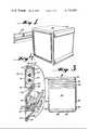
- FIG. 1is a perspective view of a modular cell unit shown attached to a wall rail
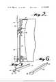
- FIG. 2is a cross sectional view of the wall rail, key, leveling key and modular cell unit,
- FIG. 3is a rear elevational view of the modular cell unit
- FIG. 4is an enlarged cross sectional view of the wall rail and key
- FIG. 5is a perspective view of the wall rail and
- FIG. 6is a perspective view of the leveling key.
- the modular cell unit 30comprises two outside walls 32 and 34, rear wall 36, top surface 38 and bottom 40.
- the entire modular cell unit and its complementary componentsare constructed of a relatively strong, heat-resistant plastic material.
- the modular cell unitis constructed without any sharp corners or seams between adjacent wall surfaces. The absence of any seams prolongs the unit's life span. The absence of the seams also prohibits any water from being trapped within the unit for any appreciable length of time. Additionally, the absence of sharp corners on the cell provides an aesthetic pleasing effect as well as an added safety feature.
- Outside wall abutment surfaces or spacing ridges 44 and 46extend outwardly from outside walls 32 and 34 respectively. These spacing ridges extend outwardly from the planar surface of the side walls. Additionally, the outside wall abutment surfaces are recessed inwardly from the outside perimeter of the side walls. The ridges are parallel to the outside perimeter of the side walls, yet recessed inwardly as previously mentioned. When two modular cell units are placed immediately adjacent to each other these outside wall abutment surfaces will contact each other at their planar contact surfaces. Consequently, the two modular cells will be spaced apart a uniform distance. The outside wall abutment surfaces or spacing ridges 44,46 add structural rigidiy to the two adjacent units.
- the abutment of the adjacent outside wall abutment surfacesprevents the accidental lodging of any foreign objects between the units and also prevents any objects from falling off the top surface of the unit to the floor.
- the uniform spacing provided between adjacent modular cell unitsprovides an aesthetically pleasing appearance, which is especially important in hospital environments.
- the ridges of the side wallscan be formed so as to interlock with the ridges of adjacent modular cell units.
- the rear wall 36is provided with a plurality of top horizontally extending slots 48.
- the slotsextend vertically upward into the rear of the cavity 43 of the modular cell unit.
- a mounting key 52is inserted into the desired top longitudinal slot 48 in order to adjust the height of the modular cell unit with respect to the wall rail.
- One leg of the mounting key 52is secured into the selected horizontal slot 48 while the other leg of the mounting key is held in place by the wall rail 54.
- the legs of mounting key 52matingly engage with the slots 48 and the wall rail 54. In this manner, the relative height of the modular cell unit can be adjusted without the need of requiring a multitude of unsightly wall rails.
- a lower leveling slot 50is also provided in the rear wall 36 of the modular cell unit 30.
- the lower leveling slotis horizontally located at the lower portion of the rear wall.
- This lower level slot 50matingly receives a leg of the leveling key 56 in a manner similar to how the top horizontal slots 48 receive key 52.
- the other leg of the leveling key 56is provided with a flat surface and is constructed to rest flush against the wall of the room.
- the modular cell unitcan be vertically adjusted by selecting the desired horizontal slot within which the mounting key 52 is to be placed, while the leveling key is always placed in the lower leveling slot 50 in order to space the lower edge of the rear wall 36 of the modular cell from the wall of the room.
- the leveling keytherefore, serves the important function of keeping the top surface 38 of the modular cell unit 30 in a level orientation with respect to the floor of the hospital room.
- the leveling key 56comprises a wall contact surface 58 and a vertically inclined slot-engaging leg 60. In operation, the slot-engaging leg 60 slides upwardly into the lower leveling slot 50.
- the leveling key and corresponding slotare constructed so that the key will remain with the unit unless the key is intentionally physically removed from the leveling slot. The fact that the key remains with the unit facilitates any change of position of the cell.
- the mounting key 52as best shown in FIG. 5, is comprised of two legs 62 and 64.
- Leg 62slides upwardly into the selected top longitudinal slot 48.
- the leg 62 and all slotsare constructed so that after the key is placed in an appropriate slot it is there held until actual physical removal takes place. This facilitates the movement of the entire modular cell from one position on the wall rail to another wall rail located elsewhere.
- the width across the lower portion of leg 62, at the point where the leg 62 turns into leg 64is a greater width than the width across the tip 66 of the leg.
- the tip 66is the first part of the wall rail to enter into the slots 48. Due to the increased width across the leg, the mounting key 52 is frictionally held in place by the top longitudinal slot's side walls.
- Leg 64engages the channel formed within the wall rail.
- Leg 64is comprised of a surface 68 which engages the wall rail.
- the tip 70 of the leg 64is the first section to enter into the channel 72.
- the ledge engaging surface 68 of leg 64sits upon ledge 76 of the wall rail.
- the mounting key and the leveling keywill remain attached to the rear of the modular cell unit unless they are physically intentionally removed. If the modular cell unit is not to be held on the wall but rather stored on the floor or on one of its associated bases then both the mounting key and rail key should be removed. The removal of the two keys facilitates storage of the units as the rear of the modular cell may now be placed flush against a wall. This is obviously not possible where the mounting key and/or leveling key are fixedly attached to the modular cell.
- the wall rail 54is comprised of two main segments.
- a wall bracket 90is first secured to the hospital's room's wall by means of suitable fasteners.
- the wall bracketis secured to the wall at an appropriate height such that the lower edge of the bracket is parallel to the floor of the room.
- the wall bracket 90is composed of a strong metal (e.g. aluminum or steel).
- the wall bracket 90has two wall-engaging flat surfaces 92 and 94. At suitable points along these flat surfaces, fasteners are drilled through the wall bracket and secured to the wall.
- the wall bracketforms a top piece 96 which extends substantially away from the wall of the room.
- a catch 98is provided at the rearmost portion of the top piece 96.
- This catch 98serves to keep the wall bracket cover piece 100 from being pulled away from the wall bracket 90.
- the wall bracketturns away from the wall to form wall bracket gripping leg 102.
- Flat piece 94has at its lower end a perpendicular ledge 110 which terminates in an upwardly inclined segment 112, inclined away from the wall.
- the perpendicular ledge 110, flat piece 94, and inclined segment 112form a "U" shape, hereinafter referred to as channel 72 of the wall rail.
- a lip 114At the outermost edge of the perpendicular piece 110 is a lip 114.
- the lowermost portion of flat piece 94has an incline 116 which extends upwardly and away from the wall bracket.
- a hard plastic wall bracket cover 100fits over the wall bracket 90 and is held securely in place at a plurality of points.
- the wall cover catch 118fits over wall bracket catch 98.
- the top piece 120 of the wall coverin addition to having the wall cover catch 118, is provided with a vertical flat piece 124.
- the vertical flat piece 124ends with a gripping leg 126. This gripping leg 126 matingly engages and holds the gripping leg 102 of the wall bracket 90.
- the cavity 128is functional in that it allows electrical wires, rubber tubing or any conduits to be passed around the room while prohibiting these conduits from being unnecessarily contaminated. Loose and open wires always have the potential for trouble and the fact that the conduits may be safely carried around the room without being open to the atmosphere is extremely beneficial. Additionally, the cavity 128 withdraws from the room the unsightly wires that tend to give a person or patient the feeling of lack of order or organization. As previously mentioned, the patient's morale in a hospital is often a crucial determining factor in the patient's physical health. From the base of the gripping leg 126 of the wall bracket cover to the ledge 76 of the inclined segment 112 the wall bracket cover follows the curvature of the wall bracket. The "U" channel 72 is thus formed, into which the wall rail engaging leg 64 of mounting key 52 is inserted for mounting the modular cell unit to the wall.
- the wall bracket coverextends vertically by planar face 132.
- a positioning leg 134 of the wall bracket cover 100rests above the lip 114 of the wall bracket and serves to space planar surface 132 away from the inclined segment 112.
- the planar surface 132ends in an inclined surface 136.
- the inclined surface 136has a longitudinal finger 138 which is positioned above the incline 116 of the wall bracket.
- An undercut 140matingly engages with the base portion of incline 116.
- the wall bracket 90is first secured to the wall of a room. Subsequently the wall bracket cover is snapped over the wall bracket and held in place at a plurality of points.
- the contact points between the wall bracket and the wall bracket coverare the catch 98 and wall cover catch 118, top piece 96 and longitudinal rib 122, gripping leg 102 and gripping leg 126, ledge 76 and wall cover horizontal surface 121, lip 114 and positioning leg 134, incline 116 and finger 138, and undercut 140 and the base of the wall bracket.
- the wall bracket coverconforms to the wall bracket in the area where the channel 72 is formed in the wall rail.
- An end cap 101is also provided which serves to close off the edges or corners of the wall rails. If desired the end cap is provided with a punchout area so as to allow any conduits traveling in cavity 128 to enter and exit the wall rail.
- An electrical outlet 103is shown which outlet extends from vertical planar surface 124 of wall bracket cover 100.
Landscapes
- Accommodation For Nursing Or Treatment Tables (AREA)
Abstract
Description
Claims (17)
Priority Applications (1)
| Application Number | Priority Date | Filing Date | Title |
|---|---|---|---|
| US05/791,317US4133507A (en) | 1977-04-27 | 1977-04-27 | System for mounting storage units |
Applications Claiming Priority (1)
| Application Number | Priority Date | Filing Date | Title |
|---|---|---|---|
| US05/791,317US4133507A (en) | 1977-04-27 | 1977-04-27 | System for mounting storage units |
Publications (1)
| Publication Number | Publication Date |
|---|---|
| US4133507Atrue US4133507A (en) | 1979-01-09 |
Family
ID=25153336
Family Applications (1)
| Application Number | Title | Priority Date | Filing Date |
|---|---|---|---|
| US05/791,317Expired - LifetimeUS4133507A (en) | 1977-04-27 | 1977-04-27 | System for mounting storage units |
Country Status (1)
| Country | Link |
|---|---|
| US (1) | US4133507A (en) |
Cited By (42)
| Publication number | Priority date | Publication date | Assignee | Title |
|---|---|---|---|---|
| US4384605A (en)* | 1981-08-18 | 1983-05-24 | Cooper Industries, Inc. | Valance support for headrail |
| US4540146A (en)* | 1983-08-29 | 1985-09-10 | Black & Decker, Inc. | Mounting arrangement |
| US4618192A (en)* | 1985-03-14 | 1986-10-21 | Herman Miller, Inc. | Cabinet with hanger rails |
| US4775127A (en)* | 1987-06-02 | 1988-10-04 | Masazo Nakamura | Device for fixing rail for hanging exhibits |
| WO1989006922A1 (en)* | 1988-01-26 | 1989-08-10 | Hendon International Hotel & Leisure Products Ltd. | Modular wall panel system |
| US4899971A (en)* | 1988-08-01 | 1990-02-13 | Plastic Development, Inc. | Display assembly |
| US5029716A (en)* | 1989-05-23 | 1991-07-09 | Hoska Gerald R | Tape cassette storage system |
| US5222611A (en)* | 1992-03-26 | 1993-06-29 | Wood Robert G | Wall-unit hanging system |
| US5368379A (en)* | 1990-04-12 | 1994-11-29 | Aktiebolaget Electrolux | Dishwasher chassis |
| US5392934A (en)* | 1993-05-14 | 1995-02-28 | Fox; Larry G. | Apparatus and method for adjustably supporting furnishings on a wall surface |
| DE19620981A1 (en)* | 1996-05-24 | 1997-11-27 | A & S Baeder Gmbh | Attachment for small article of furniture to wall |
| US5794903A (en)* | 1996-06-19 | 1998-08-18 | Peterson, Ii; Max R. | Securing apparatus |
| US6122179A (en)* | 1998-06-29 | 2000-09-19 | Lucent Technologies Inc. | Mounting tree for power transfer devices used in hybrid fiber/coaxial systems |
| US6189268B1 (en) | 1999-06-04 | 2001-02-20 | Paoli, Inc. | Modular office furniture system |
| FR2807927A1 (en)* | 2000-04-25 | 2001-10-26 | Alain Minville | Mounting system, for mounting kitchen or bathroom cupboards on wall, comprises hooked profile which is screwed on to wall, cooperating hook being screwed on to back of cupboard and spacers allowing cupboard to be aligned |
| US6341754B1 (en) | 1999-10-04 | 2002-01-29 | Hp Intellectual Corp. | Small appliance modular hanger system |
| US6527227B1 (en) | 2001-08-16 | 2003-03-04 | The Boeing Company | Storage compartment with universal mounting capability |
| FR2833821A1 (en)* | 2001-12-20 | 2003-06-27 | Optimum Sa | Suspended article of furniture e.g. shelf unit has inserts in rear edges of side panels that engage with V-section rail fixed to wall |
| US6772982B2 (en)* | 2001-09-28 | 2004-08-10 | Mitsubishi Heavy Industries, Ltd. | Mounting structure |
| US20040212959A1 (en)* | 2003-04-25 | 2004-10-28 | Rotta Phillip R. | Fixture and method for quick installation and removal of mobile platform electronic modules |
| US20060091271A1 (en)* | 2004-10-29 | 2006-05-04 | Nowak Joseph A | Wall unit support system |
| US20060138291A1 (en)* | 2004-12-29 | 2006-06-29 | Cies Edwin L | Coupling assembly for releasably connecting a trash container with a fixed object |
| US20060266906A1 (en)* | 2004-12-29 | 2006-11-30 | Cies Edwin L | Coupling assembly for releasably connecting a trash container with a fixed object |
| GB2444897A (en)* | 2006-12-22 | 2008-06-25 | Steven Bettison | Rail mounting assembly for cabinets |
| USD624317S1 (en) | 2009-09-02 | 2010-09-28 | Black & Decker Inc. | Tool container |
| US20110017690A1 (en)* | 2009-07-22 | 2011-01-27 | Wen-Tsan Wang | Wall mount storage device |
| US20110048988A1 (en)* | 2009-09-02 | 2011-03-03 | Black & Decker Inc. | Method And Package For Displaying Magnetic Tool Container |
| US7988236B2 (en) | 2007-06-15 | 2011-08-02 | Ashley Furniture Industries, Inc. | Integrated base assembly |
| US20120018396A1 (en)* | 2010-07-20 | 2012-01-26 | Susan Jr Edward T | Wall mounted shelving system |
| US8209932B2 (en)* | 2008-05-16 | 2012-07-03 | General Electric Company | Backsplash for an appliance |
| US8506108B2 (en) | 2009-02-25 | 2013-08-13 | Black & Decker Inc. | Power tool with light for illuminating a workpiece |
| JP2014005624A (en)* | 2012-06-22 | 2014-01-16 | Origin Kogyo Kk | Shelf mounting wall metal fitting |
| US8820955B2 (en) | 2009-02-25 | 2014-09-02 | Black & Decker Inc. | Power tool with light emitting assembly |
| US8827483B2 (en) | 2009-02-25 | 2014-09-09 | Black & Decker Inc. | Light for a power tool and method of illuminating a workpiece |
| US9028088B2 (en) | 2010-09-30 | 2015-05-12 | Black & Decker Inc. | Lighted power tool |
| US9242355B2 (en) | 2012-04-17 | 2016-01-26 | Black & Decker Inc. | Illuminated power tool |
| US20160045026A1 (en)* | 2014-08-13 | 2016-02-18 | Timothy James Trunkle | Cabinet hanging and aligning system and method |
| US9328915B2 (en) | 2010-09-30 | 2016-05-03 | Black & Decker Inc. | Lighted power tool |
| US10136724B2 (en)* | 2017-02-08 | 2018-11-27 | Ole Falk Smed | Bracket for mounting adjustable-height leg |
| US10619865B2 (en)* | 2014-04-21 | 2020-04-14 | Mitsubishi Electric Corporation | Air-conditioning unit |
| US11013540B2 (en) | 2018-04-13 | 2021-05-25 | Stryker European Operations Holdings Llc | Femoral nail with enhanced bone conforming geometry |
| US12059780B2 (en) | 2010-09-30 | 2024-08-13 | Black & Decker Inc. | Lighted power tool |
Citations (8)
| Publication number | Priority date | Publication date | Assignee | Title |
|---|---|---|---|---|
| US846022A (en)* | 1906-01-10 | 1907-03-05 | Barnes Mfg Company | Bracket. |
| US3071350A (en)* | 1961-01-24 | 1963-01-01 | Kenneth M Opie | Rail mounting |
| US3222116A (en)* | 1961-01-13 | 1965-12-07 | Levenberg Nat | Kitchen cabinets |
| US3330518A (en)* | 1965-08-03 | 1967-07-11 | Benjamin H Adler | Suspensory system for objects |
| US3346314A (en)* | 1964-10-06 | 1967-10-10 | Brunswick Corp | Wall wardrobe |
| US3714907A (en)* | 1970-12-09 | 1973-02-06 | R Michieli | Ceramic tile shelf and form for making it |
| GB1447422A (en)* | 1974-02-21 | 1976-08-25 | Acr Designs Ltd | Article adapted for mounting on a flat upright surface |
| US4008872A (en)* | 1975-10-08 | 1977-02-22 | Thompson Richard W | Module supporting system |
- 1977
- 1977-04-27USUS05/791,317patent/US4133507A/ennot_activeExpired - Lifetime
Patent Citations (8)
| Publication number | Priority date | Publication date | Assignee | Title |
|---|---|---|---|---|
| US846022A (en)* | 1906-01-10 | 1907-03-05 | Barnes Mfg Company | Bracket. |
| US3222116A (en)* | 1961-01-13 | 1965-12-07 | Levenberg Nat | Kitchen cabinets |
| US3071350A (en)* | 1961-01-24 | 1963-01-01 | Kenneth M Opie | Rail mounting |
| US3346314A (en)* | 1964-10-06 | 1967-10-10 | Brunswick Corp | Wall wardrobe |
| US3330518A (en)* | 1965-08-03 | 1967-07-11 | Benjamin H Adler | Suspensory system for objects |
| US3714907A (en)* | 1970-12-09 | 1973-02-06 | R Michieli | Ceramic tile shelf and form for making it |
| GB1447422A (en)* | 1974-02-21 | 1976-08-25 | Acr Designs Ltd | Article adapted for mounting on a flat upright surface |
| US4008872A (en)* | 1975-10-08 | 1977-02-22 | Thompson Richard W | Module supporting system |
Cited By (58)
| Publication number | Priority date | Publication date | Assignee | Title |
|---|---|---|---|---|
| US4384605A (en)* | 1981-08-18 | 1983-05-24 | Cooper Industries, Inc. | Valance support for headrail |
| US4540146A (en)* | 1983-08-29 | 1985-09-10 | Black & Decker, Inc. | Mounting arrangement |
| US4618192A (en)* | 1985-03-14 | 1986-10-21 | Herman Miller, Inc. | Cabinet with hanger rails |
| US4775127A (en)* | 1987-06-02 | 1988-10-04 | Masazo Nakamura | Device for fixing rail for hanging exhibits |
| WO1989006922A1 (en)* | 1988-01-26 | 1989-08-10 | Hendon International Hotel & Leisure Products Ltd. | Modular wall panel system |
| US4899971A (en)* | 1988-08-01 | 1990-02-13 | Plastic Development, Inc. | Display assembly |
| WO1991011131A1 (en)* | 1988-08-01 | 1991-08-08 | Plastic Development, Inc. | Display assembly |
| US5029716A (en)* | 1989-05-23 | 1991-07-09 | Hoska Gerald R | Tape cassette storage system |
| US5368379A (en)* | 1990-04-12 | 1994-11-29 | Aktiebolaget Electrolux | Dishwasher chassis |
| US5222611A (en)* | 1992-03-26 | 1993-06-29 | Wood Robert G | Wall-unit hanging system |
| US5392934A (en)* | 1993-05-14 | 1995-02-28 | Fox; Larry G. | Apparatus and method for adjustably supporting furnishings on a wall surface |
| DE19620981A1 (en)* | 1996-05-24 | 1997-11-27 | A & S Baeder Gmbh | Attachment for small article of furniture to wall |
| US5794903A (en)* | 1996-06-19 | 1998-08-18 | Peterson, Ii; Max R. | Securing apparatus |
| US6122179A (en)* | 1998-06-29 | 2000-09-19 | Lucent Technologies Inc. | Mounting tree for power transfer devices used in hybrid fiber/coaxial systems |
| US6189268B1 (en) | 1999-06-04 | 2001-02-20 | Paoli, Inc. | Modular office furniture system |
| US6341754B1 (en) | 1999-10-04 | 2002-01-29 | Hp Intellectual Corp. | Small appliance modular hanger system |
| FR2807927A1 (en)* | 2000-04-25 | 2001-10-26 | Alain Minville | Mounting system, for mounting kitchen or bathroom cupboards on wall, comprises hooked profile which is screwed on to wall, cooperating hook being screwed on to back of cupboard and spacers allowing cupboard to be aligned |
| US6527227B1 (en) | 2001-08-16 | 2003-03-04 | The Boeing Company | Storage compartment with universal mounting capability |
| US6772982B2 (en)* | 2001-09-28 | 2004-08-10 | Mitsubishi Heavy Industries, Ltd. | Mounting structure |
| FR2833821A1 (en)* | 2001-12-20 | 2003-06-27 | Optimum Sa | Suspended article of furniture e.g. shelf unit has inserts in rear edges of side panels that engage with V-section rail fixed to wall |
| US20040212959A1 (en)* | 2003-04-25 | 2004-10-28 | Rotta Phillip R. | Fixture and method for quick installation and removal of mobile platform electronic modules |
| US6914781B2 (en) | 2003-04-25 | 2005-07-05 | The Boeing Company | Fixture and method for quick installation and removal of mobile platform electronic modules |
| US20060091271A1 (en)* | 2004-10-29 | 2006-05-04 | Nowak Joseph A | Wall unit support system |
| US20060108486A1 (en)* | 2004-10-29 | 2006-05-25 | Nowak Joseph A | Apparatus for supporting an object on a wall |
| US20060138291A1 (en)* | 2004-12-29 | 2006-06-29 | Cies Edwin L | Coupling assembly for releasably connecting a trash container with a fixed object |
| US20060266906A1 (en)* | 2004-12-29 | 2006-11-30 | Cies Edwin L | Coupling assembly for releasably connecting a trash container with a fixed object |
| US7416160B2 (en)* | 2004-12-29 | 2008-08-26 | Cies Edwin L | Coupling assembly for releasably connecting a trash container with a fixed object |
| GB2444897B (en)* | 2006-12-22 | 2008-11-05 | Steven Bettison | Rail mounting assembly for cabinets |
| GB2444897A (en)* | 2006-12-22 | 2008-06-25 | Steven Bettison | Rail mounting assembly for cabinets |
| US7988236B2 (en) | 2007-06-15 | 2011-08-02 | Ashley Furniture Industries, Inc. | Integrated base assembly |
| US8438716B2 (en) | 2007-06-15 | 2013-05-14 | Ashley Furniture Industries, Inc. | Integrated base assembly |
| US8209932B2 (en)* | 2008-05-16 | 2012-07-03 | General Electric Company | Backsplash for an appliance |
| US8506108B2 (en) | 2009-02-25 | 2013-08-13 | Black & Decker Inc. | Power tool with light for illuminating a workpiece |
| US9352458B2 (en) | 2009-02-25 | 2016-05-31 | Black & Decker Inc. | Power tool with light for illuminating workpiece |
| US8820955B2 (en) | 2009-02-25 | 2014-09-02 | Black & Decker Inc. | Power tool with light emitting assembly |
| US8827483B2 (en) | 2009-02-25 | 2014-09-09 | Black & Decker Inc. | Light for a power tool and method of illuminating a workpiece |
| US20110017690A1 (en)* | 2009-07-22 | 2011-01-27 | Wen-Tsan Wang | Wall mount storage device |
| US20110048988A1 (en)* | 2009-09-02 | 2011-03-03 | Black & Decker Inc. | Method And Package For Displaying Magnetic Tool Container |
| US8267245B2 (en) | 2009-09-02 | 2012-09-18 | Black & Decker Inc. | Method and package for displaying magnetic tool container |
| USD624317S1 (en) | 2009-09-02 | 2010-09-28 | Black & Decker Inc. | Tool container |
| US20120018396A1 (en)* | 2010-07-20 | 2012-01-26 | Susan Jr Edward T | Wall mounted shelving system |
| US8430252B2 (en)* | 2010-07-20 | 2013-04-30 | Edward T. Susan | Wall mounted shelving system |
| US9028088B2 (en) | 2010-09-30 | 2015-05-12 | Black & Decker Inc. | Lighted power tool |
| US10543588B2 (en) | 2010-09-30 | 2020-01-28 | Black & Decker Inc. | Lighted power tool |
| US12059780B2 (en) | 2010-09-30 | 2024-08-13 | Black & Decker Inc. | Lighted power tool |
| US9328915B2 (en) | 2010-09-30 | 2016-05-03 | Black & Decker Inc. | Lighted power tool |
| US9644837B2 (en) | 2010-09-30 | 2017-05-09 | Black & Decker Inc. | Lighted power tool |
| US11090786B2 (en) | 2010-09-30 | 2021-08-17 | Black & Decker Inc. | Lighted power tool |
| US9242355B2 (en) | 2012-04-17 | 2016-01-26 | Black & Decker Inc. | Illuminated power tool |
| US10173307B2 (en) | 2012-04-17 | 2019-01-08 | Black & Decker Inc. | Illuminated power tool |
| JP2014005624A (en)* | 2012-06-22 | 2014-01-16 | Origin Kogyo Kk | Shelf mounting wall metal fitting |
| US10619865B2 (en)* | 2014-04-21 | 2020-04-14 | Mitsubishi Electric Corporation | Air-conditioning unit |
| US9668576B2 (en)* | 2014-08-13 | 2017-06-06 | Timothy James Trunkle | Cabinet hanging and aligning system and method |
| US20160045026A1 (en)* | 2014-08-13 | 2016-02-18 | Timothy James Trunkle | Cabinet hanging and aligning system and method |
| US10136724B2 (en)* | 2017-02-08 | 2018-11-27 | Ole Falk Smed | Bracket for mounting adjustable-height leg |
| US11013540B2 (en) | 2018-04-13 | 2021-05-25 | Stryker European Operations Holdings Llc | Femoral nail with enhanced bone conforming geometry |
| US11730525B2 (en) | 2018-04-13 | 2023-08-22 | Stryker European Operations Holdings Llc | Femoral nail with enhanced bone conforming geometry |
| US12310636B2 (en) | 2018-04-13 | 2025-05-27 | Stryker European Operations Holdings Llc | Femoral nail with enhanced bone conforming geometry |
Similar Documents
| Publication | Publication Date | Title |
|---|---|---|
| US4133507A (en) | System for mounting storage units | |
| US4165852A (en) | Wall rail with channels | |
| US6497185B1 (en) | Slidable unit for modular shelving system | |
| US5076442A (en) | Shoe organizational system for closets | |
| US4140356A (en) | Storage unit | |
| EP0045812B1 (en) | Kitchen apparatus | |
| US4618192A (en) | Cabinet with hanger rails | |
| EP3599937B1 (en) | Drawer for wall mounted storage system | |
| US5037165A (en) | Drawer organizer comprising readily attachable low friction slides and movable tray | |
| US6336692B1 (en) | Cabinet with downward extendable/retractable shelves | |
| US6227636B1 (en) | Refrigerator shelf and serving tray assembly | |
| US6817688B2 (en) | Mounting assembly for a refrigerator storage drawer | |
| US2923584A (en) | Cabinet assembly | |
| JP2014531947A (en) | Tools, especially devices for storing tools | |
| US20130088134A1 (en) | Modular storage and organization system for existing cabinets | |
| JP5192131B2 (en) | Drawer part of furniture | |
| US20060091768A1 (en) | Adjustable door-mounted rack | |
| US5158186A (en) | Hanging file system | |
| US4108519A (en) | Pull tray | |
| JP2000225125A (en) | Storage cabinets, especially those for hospital necessities | |
| US3190712A (en) | Interior decorator's cabinet with slidable racks | |
| US5118177A (en) | Drawer and drawer suspension system | |
| KR20160001263U (en) | Multi-fetched expressions cabinet | |
| WO2000021407A2 (en) | Furniture construction | |
| EP1067852B1 (en) | Wall cupboard with self-moving shelves by means of a guide track which is assembled inside and which is fixed to the wall |
Legal Events
| Date | Code | Title | Description |
|---|---|---|---|
| AS | Assignment | Owner name:AMERICAN STERILIZER COMPANY, 2222 WEST GRANDVIEW B Free format text:ASSIGNMENT OF ASSIGNORS INTEREST.;ASSIGNOR:COMERCO, INC.;REEL/FRAME:003946/0501 Effective date:19811230 | |
| AS | Assignment | Owner name:MORGAN GUARANTY TRUST COMPANY, 23 WALL STREET, NEW Free format text:SECURITY INTEREST;ASSIGNOR:AMERICAN STERILIZER COMPANY, A PA CORP.;REEL/FRAME:004765/0752 Effective date:19870827 Owner name:MORGAN GUARANTY TRUST COMPANY,NEW YORK Free format text:SECURITY INTEREST;ASSIGNOR:AMERICAN STERILIZER COMPANY, A PA CORP.;REEL/FRAME:004765/0752 Effective date:19870827 | |
| AS | Assignment | Owner name:AMERICAN STERILIZER COMPANY, ONE MELLON BANK CENTE Free format text:RELEASED BY SECURED PARTY;ASSIGNOR:MORGAN GUARANTY TRUST COMPANY OF NEW YORK;REEL/FRAME:005581/0543 Effective date:19910130 | |
| AS | Assignment | Owner name:XYTEC PLASTICS, INC., 9350 47TH AVENUE S.W., TACOM Free format text:ASSIGNMENT OF ASSIGNORS INTEREST.;ASSIGNOR:AMERICAN STERILIZER COMPANY, A PA CORP.;REEL/FRAME:005589/0815 Effective date:19910131 | |
| AS | Assignment | Owner name:XYTEC PLASTICS, INC., WASHINGTON Free format text:RELEASED BY SECURED PARTY;ASSIGNOR:AMERICAN STERILIZER COMPANY A CORP. OF PA;REEL/FRAME:006148/0019 Effective date:19920407 |