US4129224A - Automatic control of backhoe digging depth - Google Patents
Automatic control of backhoe digging depthDownload PDFInfo
- Publication number
- US4129224A US4129224AUS05/833,432US83343277AUS4129224AUS 4129224 AUS4129224 AUS 4129224AUS 83343277 AUS83343277 AUS 83343277AUS 4129224 AUS4129224 AUS 4129224A
- Authority
- US
- United States
- Prior art keywords
- angle
- boom
- digging
- bucket
- downreach
- Prior art date
- Legal status (The legal status is an assumption and is not a legal conclusion. Google has not performed a legal analysis and makes no representation as to the accuracy of the status listed.)
- Expired - Lifetime
Links
Images

Classifications
- E—FIXED CONSTRUCTIONS
- E02—HYDRAULIC ENGINEERING; FOUNDATIONS; SOIL SHIFTING
- E02F—DREDGING; SOIL-SHIFTING
- E02F3/00—Dredgers; Soil-shifting machines
- E02F3/04—Dredgers; Soil-shifting machines mechanically-driven
- E02F3/28—Dredgers; Soil-shifting machines mechanically-driven with digging tools mounted on a dipper- or bucket-arm, i.e. there is either one arm or a pair of arms, e.g. dippers, buckets
- E02F3/36—Component parts
- E02F3/42—Drives for dippers, buckets, dipper-arms or bucket-arms
- E02F3/43—Control of dipper or bucket position; Control of sequence of drive operations
- E02F3/435—Control of dipper or bucket position; Control of sequence of drive operations for dipper-arms, backhoes or the like
- E—FIXED CONSTRUCTIONS
- E02—HYDRAULIC ENGINEERING; FOUNDATIONS; SOIL SHIFTING
- E02F—DREDGING; SOIL-SHIFTING
- E02F3/00—Dredgers; Soil-shifting machines
- E02F3/04—Dredgers; Soil-shifting machines mechanically-driven
- E02F3/28—Dredgers; Soil-shifting machines mechanically-driven with digging tools mounted on a dipper- or bucket-arm, i.e. there is either one arm or a pair of arms, e.g. dippers, buckets
- E02F3/30—Dredgers; Soil-shifting machines mechanically-driven with digging tools mounted on a dipper- or bucket-arm, i.e. there is either one arm or a pair of arms, e.g. dippers, buckets with a dipper-arm pivoted on a cantilever beam, i.e. boom
- E02F3/32—Dredgers; Soil-shifting machines mechanically-driven with digging tools mounted on a dipper- or bucket-arm, i.e. there is either one arm or a pair of arms, e.g. dippers, buckets with a dipper-arm pivoted on a cantilever beam, i.e. boom working downwardly and towards the machine, e.g. with backhoes
- E—FIXED CONSTRUCTIONS
- E02—HYDRAULIC ENGINEERING; FOUNDATIONS; SOIL SHIFTING
- E02F—DREDGING; SOIL-SHIFTING
- E02F9/00—Component parts of dredgers or soil-shifting machines, not restricted to one of the kinds covered by groups E02F3/00 - E02F7/00
- E02F9/26—Indicating devices
Definitions
- the aforedescribed apparatuscontinuously indicates to the operator the depth position of the digging teeth of the backhoe, but it is still left to the operator's skill to manipulate the various control levers which respectively control the three primary hydraulic cylinders involved in the operation of the backhoe, to cause the digging teeth to move in a path parallel to a desired reference plane and thus produce a trench bottom of not only the desired depth but also the proper slope.
- the speed of the digging operation employing a backhoeis primarily determined by the rate of change of the angle between the outreach boom and the downreach boom of the backhoe. If the operator could concentrate on changing this angle during the digging stoke as rapidly as permitted by the soil conditions, without having to concurrently adjust the cylinders controlling the two other basic angles of the backhoe, the speed of the digging operation could be measurably increased, but no apparatus has heretofore been provided that would permit the operator to manually control only the hydraulic cylinder which determines the aforementioned angle and still maintain the digging teeth of the backhoe moving along a plane parallel to the desired slope of the bottom of the excavation.
- Another object of the inventionis to provide apparatus for automatically controlling two of the three primary angles involved in the operation of a backhoe so that irrespective of the rate of change of the angle between the outreach boom and the downreach boom, the teeth of the digging bucket will follow a path parallel to the desired slope of the bottom of the excavation.
- a further object of the inventionis to provide apparatus for automatically controlling two of the three primary angles involved in the operation of a backhoe as a function of the third primary angle and the angle of the desired slope of excavation with respect to the horizontal so that the teeth or edge of the digging bucket will not only follow a path parallel to the desired slope of the bottom of the excavation but will also maintain a constant angle of attack with respect to the bottom of the excavation.
- a particular object of this inventionis to provide a control apparatus for a backhoe wherein the absolute digging depth of the teeth of the backhoe is continuously indicated relative to a reference plane defined by a rotating laser beam and the cylinders controlling the primary angles of the backhoe are controlled either manually or automatically to consistently move the digging teeth of the backhoe along a plane parallel to the reference plane defined by the rotating laser beam.
- FIG. 1is a side elevational, schematic view of a prior art form of backhoe mounted on an industrial tractor and embodying digging depth indicating and controlling apparatus.
- FIG. 2is a schematic representation of the movable elements of the backhoe of FIG. 1 for the purpose of trigonometric analysis of the position of the cutting teeth of the backhoe.
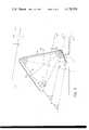
- FIG. 3is a view similar to FIG. 2, but using only lines to represent the components of the backhoe as the digging edge or teeth of the digging bucket are moved in a digging stroke along a plane parallel to that defined by a reference plane created by rotating a laser beam above the working area and the digging angle of the bucket relative to the said plane is maintained at a constant angle.
- such backhoescomprise an outreach boom 11 formed by two spaced triangular plate members suitably secured together by weldments to form a rigid truss element.
- the forward end of outreach boom 11is appropriately secured to a transverse shaft 4a journalled by a mounting bracket 4.
- Bracket 4is pivotally mounted to vehicle 1 for horizontal swinging movements by conventional means (not shown).
- Hydraulic cylinder 5operates between the bracket 4 and the outreach boom 11 to control the vertical pivotal position of said outreach boom 11 relative to the vehicle.
- a pair of laterally projecting stabilizing pads 8are also attached to vehicle 1 in conventional fashion.
- a downreach boom 12comprises a main structural frame element 12a to which a pair of generally triangular plates 12b are respectively secured by welding in opposed relationship.
- the plates 12bare traversed by the mounting pin 13 and also support a pivotal mounting pin 12c which receives the end of a cylinder unit 6 which operates between the outreach boom 11 and the downreach boom 12 to control the relative angular positions of said booms.
- a third pivot mounting pin 12dprovides a pivot mounting for a cylinder unit 7 which controls the pivotal position of a digging bucket 14 which is pivotally mounted to the free end of the downreach boom 12 as by pivot pin 14a.
- Bucket 14is of conventional configuration and has digging teeth 14b at its extreme lower edge. Obviously, it is the vertical position or depth of the digging teeth 14b that determines the effective digging depth of the bucket 14.
- Each of the cylinders 5, 6 and 7 respectively controlling the position of the outreach boom 11 relative to the vehicle, the pivotal position of the downreach boom 12 relative to the outreach boom 11, and the position of the bucket 14 with respect to the end of the downreach boom 12,is normally manually controlled by conventional individual hydraulic controls positioned immediately adjacent the operator's seat on the vehicel 1.
- the digging bucketmay be moved to a digging position beneath the ground.
- the path of the digging bucket through the groundis obviously controlled by the operator by making the appropriate variations of the relative angles between the outreach boom 11, the downreach boom 12 and the digging bucket 14.
- Transducers T1, T2 and T3are respectively mounted.
- Transducers T1, T2 and T3are of a conventional type which produce an electrical signal proportional to the angular displacement of the shaft (not shown) relative to the circular body 21 of the transducer.
- the transducermay be the type manufactured and sold by Trans-Tek, Inc. of Ellington, Connecticut.
- the shaft of transducer T1is suitably co-axially secured to an extension 4b of the pivot mounting shaft 4a.
- the shaft of transducer T2is suitably secured to the pin 13 by which the downreach boom 12 is pivotally secured to the outreach boom 11.
- transducer T3is secured to the pivot shaft 14a by which the digging bucket 14 is pivotally secured to the end of the downreach boom 12.
- Suitable brackets 22are provided for mounting the cylindrical body portions 21 of each of the transducers T1, T2 and T3 so that any movement of the respective booms produces a movement of the shafts relative to the body portion 21 of the particular transducer mounted at such pivotal axis.
- Bracket 22 of transducer T1is secured to pendulum 42 to produce a signal proportional to the angle A between the boom 11 and the horizontal.
- the distance R1represents the effective length of the outreach boom 11 between the pivot mounting pins 4a and 13.
- the distance R2is the effective length of the downreach boom 12 between the pivot pins 13 and 14a.
- the distance R3is the effective distance from the pivot mounting pin 14a, by which the digging bucket is secured to the downreach boom, to the end of the digging teeth 14b.
- the angle Ais the angle between the outreach boom 11 and the horizontal
- the angle Bis the angle between the outreach boom 11 and the downreach boom 12
- the angle Cis the effective angle between the downreach boom 12 and the line R3 drawn between the digging teeth and the pivot mounting axis 14a of the bucket 14.
- the distance D between the pivot axis 4a provided on the vehicle for mounting the outreach boom 11 and the digging depth of the teeth 14b of the bucket 14may be found to be determined by the following equation:
- appropriate electrical circuitryis set up to effect the combination of signals respectively proportional to R1, R2, R3, sin A, sin (A + B) and sin (A + B + C), resulting in an electrical signal proportional to D, which is the distance from the pivot axis 4a on the vehicle bracket 4 to the digging teeth 14b of the backhoe bucket 14.
- This signalmay be read on an appropriate ammeter or voltmeter 25 which is calibrated in appropriate depth units.
- the vertical height of the pivot axis of the backhoemay very well shift during the digging operation, due to the weight of the vehicle effecting a settling of the vehicle support pads 8. Accordingly, if it is desired to know in absolute terms the working depth of the teeth 14b of the backhoe bucket, then it is necessary to know the absolute height of the pivot axis 4a with respect to a reference plane.
- a reference planemay be defined by a laser beam L which is periodically swept over the area.
- the apparatus for generating such rotating laser beammay be that disclosed in Studebaker Patent, U.S. Pat. No. 3,588,249.
- an upstanding mast 40is provided constituting an extension of pendulum 42 having the bottom end thereof pivotally mounted on extension 4b of the pivot pin 4a which mounts the outreach boom 11 to the bracket 4.
- Mast 40is supported in a true vertical position by the pendulum weight 42 positioned below the pivot mounting pin 4b.
- Mast 40may be identical to that disclosed in my earlier U.S. Pat. No. 3,825,808 and incorporates a motor 43 for extending or contracting the vertical height of mast 40.
- a laser beam sensor unit 44is mounted comprising a plurality of vertically stacked cells (not shown) which generate electrical signals when impinged by the laser beam L. The same circuitry as described in my prior U.S. Pat.
- No. 3,825,808may be employed to automatically effect the raising or lowering of mast 40 through the operation of the motor 43 to keep the center of the vertically stacked array of laser beam receiving cells in exact alignment with the reference plane defined by the laser beam L.
- the resulting vertical movements of the mast 40may be translated into a rotational movement as described in said patent and such rotational movement detected by a transducer T4 (FIG. 2), thus producing an electrical signal proportional to the height of the mast 40, hence proportional to the absolute vertical spacing H (FIG. 2) between the pivot axis 4a and the reference plane defined by the laser beam L.
- the signal from transducer T4may be added to the signal D and thus the indicating instrument 25 will now indicate the absolute elevation, or displacement of the cutting teeth 14b of the backhoe bucket relative to the reference plane defined by the laser beam L.
- the plane defined by the rotating laser beam Lis shown as being at a slight inclination angle S relative to the true horizontal indicated by the line Ho.
- Thisis a common situation encountered when a backhoe is utilized for a trenching operation.
- Thereis schematically shown in solid lines the primary elements of the backhoe at any position in a digging stroke and, by dotted line L1, the path of the digging edge or teeth f as the digging teeth of the backhoe move in a plane parallel to a reference plane defined by the rotating laser beam L, which is at an angle S to the horizontal Ho. It is readily apparent that some relationship between the angles A, B, C and S must be maintained in order to have the digging edge or teeth f of the bucket move as indicated in FIG. 3.
- This inventionpermits the teeth or digging edge of the backhoe bucket to not only be readily controlled to move along a path parallel to the desired slope of the bottom of the excavation, but concurrently the digging angle or attack angle of the bucket may be maintained at a constant value relative to the bottom of the excavation to provide a consistent bite of the bucket throughout the digging stroke.
- the attack angle referred tois the angle F, and it should be noted that this angle is maintained at the constant value throughout the digging stroke.
- the angle Cmust necessarily vary, and, in accordance with this invention, means are provided for automatically controlling the angle C so that the attack angle F remains at a constant value throughout the digging stroke.
- FIG. 3clarifies the trigonometric relationship between the various angles involved in this mode of operation of the backhoe.
- FIG. 3is similar to FIG. 2, except that line L1 representing the desired trench bottom, has been extended out to meet an extension of the line 11 representing the outreach boom.
- the angle between the extension of line 11 and the line L1is referred to as angle A + S because this is its value.
- angle Cis equal to K2 minus (A + B) and angle A is equal to K2 minus (B + C).
- the angles A, B, and Care known and their values are indicated by electrical signals respectively generated by the transducers T1, T2, and T3. Therefore, through the application of conventional circuitry, the angle C may be automatically controlled as a function of angles A and B through application of a signal to the hydraulic valve controlling the cylinder 7, which signal is determined by the above equation for the angle C.
- the angle Amay be automatically determined by applying a signal to the control valve for the hydraulic cylinder 5 which is determined as a function of angle B from the following analysis based on FIG. 3 on which:
- Lines L2 and L3are drawn through points ⁇ c ⁇ and ⁇ a ⁇ respectively and are parallel to L1.
- Line b o q pis drawn through point ⁇ b ⁇ perpendicular to lines L3, L2 and L1.
- Line c gis drawn through point ⁇ c ⁇ perpendicular to line 11.
- Line c dis drawn through point ⁇ c ⁇ perpendicular to line L3.
- Line e fis drawn through point ⁇ f ⁇ perpendicular to line L2.
- angle Amay be determined at any point in the digging stroke as a function of angle B known constants R1, R2 and K.
- the constant Kmay be computed from the known values of angles A, B and S at the beginning of the digging stroke from the equation
- a o and B oare the measured values of angles A and B at the beginning of the digging stroke.
- a number of micro-processors or mini-computersare available in the trade which may be programmed to calculate the value of K from the values of Angles A o , B o , Angle S and the lengths R1 and R2.
- the same or a similar mini-computercan be programmed to calculate the value of the Angle A according to the arc sine equation set forth above by feeding to the computer signals proportional to Angle B, Angle S and the lengths R1 and R2.
- the signal representing the output of this calculationis applied to control the hydraulic cylinder 6 which determines Angle A.
Landscapes
- Engineering & Computer Science (AREA)
- Mechanical Engineering (AREA)
- Mining & Mineral Resources (AREA)
- Civil Engineering (AREA)
- General Engineering & Computer Science (AREA)
- Structural Engineering (AREA)
- Operation Control Of Excavators (AREA)
Abstract
Description
D = R1 sin A - R2 sin (A + B) = R3 sin (A + B + C).
A + S + B + C + F = 360° (sum of interior angles of four-sided polygon = 360°
A + S + B + C = 360° - F = K1 (a constant)
A + B + C = K2 (another constant)
x2 + A + S + B = 180°
x2 = 180° - A - S - B
x1 = C - x2 = A + S + B + C - 180°
x3 + A + S + 90° = 180°
x3 = 90° - A - S
x4 = B - x3 = A + S + B - 90°
x5 = A + S + x
A = S + x - x5
ef = pq = R3 sin x1 = R3 sin (A + S + B + C - 180° = constant
R3 sin (A + S + B + C - 180°) = - R3 (sin A + S + B) = constant
qb = R2 cos x4 = R2 cos (A + S + B - 90°) = R2 sin (A + S + B)
ob = R1 sin (A + S)
K = cd = oq = gb = qb - ob = R2 sin (A + S + B) - R1 sin (A+S)
ag = R1 - bg = R1 - R2 cos B
cg = R2 sin B
ac = [(R2 sin B).sup.2 + (R1 - R2 cos B).sup.2 ].sup.1/2
x5 = sin.sup.-1 (cg/ac)
ad = (ac).sup.2 - K.sup.2 1/2
x = sin.sup.-1 (K/ac)
K = R2 sin (A.sub.o + S + B.sub.o) - R1 sin (A.sub.o + S)
Claims (6)
K = R2 sin (A.sub.o + S + B.sub.o) - R1 sin (A.sub.o + S)
K = R2 sin (A.sub.o + S + B.sub.o) - R1 sin (A.sub.o + S)
Priority Applications (1)
| Application Number | Priority Date | Filing Date | Title |
|---|---|---|---|
| US05/833,432US4129224A (en) | 1977-09-15 | 1977-09-15 | Automatic control of backhoe digging depth |
Applications Claiming Priority (1)
| Application Number | Priority Date | Filing Date | Title |
|---|---|---|---|
| US05/833,432US4129224A (en) | 1977-09-15 | 1977-09-15 | Automatic control of backhoe digging depth |
Publications (1)
| Publication Number | Publication Date |
|---|---|
| US4129224Atrue US4129224A (en) | 1978-12-12 |
Family
ID=25264403
Family Applications (1)
| Application Number | Title | Priority Date | Filing Date |
|---|---|---|---|
| US05/833,432Expired - LifetimeUS4129224A (en) | 1977-09-15 | 1977-09-15 | Automatic control of backhoe digging depth |
Country Status (1)
| Country | Link |
|---|---|
| US (1) | US4129224A (en) |
Cited By (48)
| Publication number | Priority date | Publication date | Assignee | Title |
|---|---|---|---|---|
| US4231700A (en)* | 1979-04-09 | 1980-11-04 | Spectra-Physics, Inc. | Method and apparatus for laser beam control of backhoe digging depth |
| EP0019949A3 (en)* | 1979-05-14 | 1981-01-21 | Ballast-Nedam Groep N.V. | Method of steering a dredger implement and dredger implement |
| USD260972S (en) | 1979-03-19 | 1981-09-29 | Sharpe Larry C | Backhoe depth gauge |
| WO1981002904A1 (en)* | 1980-04-11 | 1981-10-15 | Digger Meter Corp | Depth monitoring system |
| US4343099A (en)* | 1979-11-28 | 1982-08-10 | Ziegler Ag | Apparatus for the parallel guidance of the bucket of a hydraulic excavator |
| FR2508075A1 (en)* | 1981-06-18 | 1982-12-24 | Formanek Jiri | DEVICE FOR VERIFYING THE DEPTH OF AN EXCAVATION |
| US4491927A (en)* | 1980-04-11 | 1985-01-01 | The Digger Meter Corporation | Depth monitoring system |
| US4633383A (en)* | 1983-04-21 | 1986-12-30 | Kabushiki Kaisha Komatsu Seisakusho | Method of supervising operating states of digging machines |
| US4677555A (en)* | 1983-11-28 | 1987-06-30 | Syndicat National Des Entreprises De Drainage | Method and equipment for automatic guidance of earthmoving machines and especially machines for laying drainage elements |
| US4805086A (en)* | 1987-04-24 | 1989-02-14 | Laser Alignment, Inc. | Apparatus and method for controlling a hydraulic excavator |
| US4829418A (en)* | 1987-04-24 | 1989-05-09 | Laser Alignment, Inc. | Apparatus and method for controlling a hydraulic excavator |
| US4866641A (en)* | 1987-04-24 | 1989-09-12 | Laser Alignment, Inc. | Apparatus and method for controlling a hydraulic excavator |
| US4884939A (en)* | 1987-12-28 | 1989-12-05 | Laser Alignment, Inc. | Self-contained laser-activated depth sensor for excavator |
| US4889466A (en)* | 1985-07-26 | 1989-12-26 | Kabushiki Kaisha Komatsu Seisakusho | Control device for a power shovel |
| US4888890A (en)* | 1988-11-14 | 1989-12-26 | Spectra-Physics, Inc. | Laser control of excavating machine digging depth |
| US4945221A (en)* | 1987-04-24 | 1990-07-31 | Laser Alignment, Inc. | Apparatus and method for controlling a hydraulic excavator |
| GB2228507A (en)* | 1989-02-24 | 1990-08-29 | John Kelly | Control apparatus for earthworking machines |
| FR2671625A1 (en)* | 1991-01-16 | 1992-07-17 | Tosi Maurice | Device for determining the position of the tool of a works machine |
| WO1994013892A1 (en)* | 1992-12-07 | 1994-06-23 | Marko Nuotio | Gas/liquid accumulator for a level difference measuring apparatus and apparatus for level difference measurement |
| US5363304A (en)* | 1991-01-23 | 1994-11-08 | Shin Caterpillar Mitsubishi, Ltd. | Method for controlling a hydraulic excavator |
| US5528498A (en)* | 1994-06-20 | 1996-06-18 | Caterpillar Inc. | Laser referenced swing sensor |
| US5559725A (en)* | 1994-10-07 | 1996-09-24 | Laser Alignment, Inc. | Automatic depth control for trencher |
| US5572809A (en)* | 1995-03-30 | 1996-11-12 | Laser Alignment, Inc. | Control for hydraulically operated construction machine having multiple tandem articulated members |
| US5713144A (en)* | 1993-11-30 | 1998-02-03 | Komatsu Ltd. | Linear excavation control apparatus for a hydraulic power shovel |
| US5848485A (en)* | 1996-12-27 | 1998-12-15 | Spectra Precision, Inc. | System for determining the position of a tool mounted on pivotable arm using a light source and reflectors |
| US5933346A (en)* | 1996-06-05 | 1999-08-03 | Topcon Laser Systems, Inc. | Bucket depth and angle controller for excavator |
| US5953838A (en)* | 1997-07-30 | 1999-09-21 | Laser Alignment, Inc. | Control for hydraulically operated construction machine having multiple tandem articulated members |
| US5960378A (en)* | 1995-08-14 | 1999-09-28 | Hitachi Construction Machinery Co., Ltd. | Excavation area setting system for area limiting excavation control in construction machines |
| US6115660A (en)* | 1997-11-26 | 2000-09-05 | Case Corporation | Electronic coordinated control for a two-axis work implement |
| US6133991A (en)* | 1998-11-16 | 2000-10-17 | Apache Technologies, Inc. | Multi-segment composite photocell device |
| US6152238A (en)* | 1998-09-23 | 2000-11-28 | Laser Alignment, Inc. | Control and method for positioning a tool of a construction apparatus |
| US6209232B1 (en)* | 1996-09-04 | 2001-04-03 | Shin Caterpillar Mitsubishi Ltd. | Construction machine with function of measuring finishing accuracy of floor face smoothed thereby |
| US6233511B1 (en) | 1997-11-26 | 2001-05-15 | Case Corporation | Electronic control for a two-axis work implement |
| US6263595B1 (en) | 1999-04-26 | 2001-07-24 | Apache Technologies, Inc. | Laser receiver and angle sensor mounted on an excavator |
| US20020190197A1 (en)* | 2001-06-19 | 2002-12-19 | Jun Sasagawa | Photodetection device |
| US7012237B1 (en) | 2003-10-29 | 2006-03-14 | Apache Technologies, Inc. | Modulated laser light detector |
| US20060123673A1 (en)* | 2004-11-23 | 2006-06-15 | Caterpillar Inc. | Grading control system |
| US20060124323A1 (en)* | 2004-11-30 | 2006-06-15 | Caterpillar Inc. | Work linkage position determining system |
| US20060225310A1 (en)* | 2005-04-12 | 2006-10-12 | Koch Roger D | Work machine alignment system and method of maintaining alignment of a work machine |
| US20080015811A1 (en)* | 2006-07-12 | 2008-01-17 | Apache Technologies, Inc. | Handheld laser light detector with height correction, using a GPS receiver to provide two-dimensional position data |
| US7323673B1 (en) | 2005-03-16 | 2008-01-29 | Apache Technologies, Inc. | Modulated laser light detector with discrete fourier transform algorithm |
| US20080125942A1 (en)* | 2006-06-30 | 2008-05-29 | Page Tucker | System and method for digging navigation |
| US7838808B1 (en) | 2005-03-16 | 2010-11-23 | Trimble Navigation Limited | Laser light detector with reflection rejection algorithm |
| US20110091308A1 (en)* | 2007-12-19 | 2011-04-21 | Mark Nichols | Loader and loader control system |
| US20110311342A1 (en)* | 2007-10-26 | 2011-12-22 | Deere And Company | Three dimensional feature location from an excavator |
| CN102864800A (en)* | 2012-10-23 | 2013-01-09 | 中联重科股份有限公司渭南分公司 | Horizontal pushing control method and control device for excavator and excavator |
| US9211832B1 (en)* | 2012-05-16 | 2015-12-15 | S.A.S. Of Luxemburg, Ltd. | Salvage hold down attachment for excavators |
| US20160054114A1 (en)* | 2014-08-25 | 2016-02-25 | Trimble Navigation Limited | All-in-one integrated sensing device for machine control |
Citations (4)
| Publication number | Priority date | Publication date | Assignee | Title |
|---|---|---|---|---|
| US3586184A (en)* | 1969-02-18 | 1971-06-22 | Westinghouse Electric Corp | Control apparatus and method for an excavating shovel |
| SU397603A1 (en)* | 1971-09-24 | 1973-09-17 | VPTB ^ c ^ - ^ pGPTPTs0:> & -. S: ;;. (I b «J i | |
| US3997071A (en)* | 1975-08-14 | 1976-12-14 | Laserplane Corporation | Method and apparatus for indicating effective digging depth of a backhoe |
| US4044610A (en)* | 1975-03-12 | 1977-08-30 | Akermans Verkstad Ab | Excavators |
- 1977
- 1977-09-15USUS05/833,432patent/US4129224A/ennot_activeExpired - Lifetime
Patent Citations (4)
| Publication number | Priority date | Publication date | Assignee | Title |
|---|---|---|---|---|
| US3586184A (en)* | 1969-02-18 | 1971-06-22 | Westinghouse Electric Corp | Control apparatus and method for an excavating shovel |
| SU397603A1 (en)* | 1971-09-24 | 1973-09-17 | VPTB ^ c ^ - ^ pGPTPTs0:> & -. S: ;;. (I b «J i | |
| US4044610A (en)* | 1975-03-12 | 1977-08-30 | Akermans Verkstad Ab | Excavators |
| US3997071A (en)* | 1975-08-14 | 1976-12-14 | Laserplane Corporation | Method and apparatus for indicating effective digging depth of a backhoe |
Cited By (60)
| Publication number | Priority date | Publication date | Assignee | Title |
|---|---|---|---|---|
| USD260972S (en) | 1979-03-19 | 1981-09-29 | Sharpe Larry C | Backhoe depth gauge |
| US4231700A (en)* | 1979-04-09 | 1980-11-04 | Spectra-Physics, Inc. | Method and apparatus for laser beam control of backhoe digging depth |
| EP0019949A3 (en)* | 1979-05-14 | 1981-01-21 | Ballast-Nedam Groep N.V. | Method of steering a dredger implement and dredger implement |
| US4343099A (en)* | 1979-11-28 | 1982-08-10 | Ziegler Ag | Apparatus for the parallel guidance of the bucket of a hydraulic excavator |
| WO1981002904A1 (en)* | 1980-04-11 | 1981-10-15 | Digger Meter Corp | Depth monitoring system |
| US4491927A (en)* | 1980-04-11 | 1985-01-01 | The Digger Meter Corporation | Depth monitoring system |
| FR2508075A1 (en)* | 1981-06-18 | 1982-12-24 | Formanek Jiri | DEVICE FOR VERIFYING THE DEPTH OF AN EXCAVATION |
| US4633383A (en)* | 1983-04-21 | 1986-12-30 | Kabushiki Kaisha Komatsu Seisakusho | Method of supervising operating states of digging machines |
| US4677555A (en)* | 1983-11-28 | 1987-06-30 | Syndicat National Des Entreprises De Drainage | Method and equipment for automatic guidance of earthmoving machines and especially machines for laying drainage elements |
| US4889466A (en)* | 1985-07-26 | 1989-12-26 | Kabushiki Kaisha Komatsu Seisakusho | Control device for a power shovel |
| US4805086A (en)* | 1987-04-24 | 1989-02-14 | Laser Alignment, Inc. | Apparatus and method for controlling a hydraulic excavator |
| US4829418A (en)* | 1987-04-24 | 1989-05-09 | Laser Alignment, Inc. | Apparatus and method for controlling a hydraulic excavator |
| US4866641A (en)* | 1987-04-24 | 1989-09-12 | Laser Alignment, Inc. | Apparatus and method for controlling a hydraulic excavator |
| US4945221A (en)* | 1987-04-24 | 1990-07-31 | Laser Alignment, Inc. | Apparatus and method for controlling a hydraulic excavator |
| US4884939A (en)* | 1987-12-28 | 1989-12-05 | Laser Alignment, Inc. | Self-contained laser-activated depth sensor for excavator |
| US4888890A (en)* | 1988-11-14 | 1989-12-26 | Spectra-Physics, Inc. | Laser control of excavating machine digging depth |
| GB2228507A (en)* | 1989-02-24 | 1990-08-29 | John Kelly | Control apparatus for earthworking machines |
| GB2228507B (en)* | 1989-02-24 | 1993-03-24 | John Kelly | A method of producing a desired contouring of a work surface |
| FR2671625A1 (en)* | 1991-01-16 | 1992-07-17 | Tosi Maurice | Device for determining the position of the tool of a works machine |
| US5363304A (en)* | 1991-01-23 | 1994-11-08 | Shin Caterpillar Mitsubishi, Ltd. | Method for controlling a hydraulic excavator |
| WO1994013892A1 (en)* | 1992-12-07 | 1994-06-23 | Marko Nuotio | Gas/liquid accumulator for a level difference measuring apparatus and apparatus for level difference measurement |
| US5713144A (en)* | 1993-11-30 | 1998-02-03 | Komatsu Ltd. | Linear excavation control apparatus for a hydraulic power shovel |
| US5528498A (en)* | 1994-06-20 | 1996-06-18 | Caterpillar Inc. | Laser referenced swing sensor |
| US5559725A (en)* | 1994-10-07 | 1996-09-24 | Laser Alignment, Inc. | Automatic depth control for trencher |
| US5572809A (en)* | 1995-03-30 | 1996-11-12 | Laser Alignment, Inc. | Control for hydraulically operated construction machine having multiple tandem articulated members |
| US5960378A (en)* | 1995-08-14 | 1999-09-28 | Hitachi Construction Machinery Co., Ltd. | Excavation area setting system for area limiting excavation control in construction machines |
| US5933346A (en)* | 1996-06-05 | 1999-08-03 | Topcon Laser Systems, Inc. | Bucket depth and angle controller for excavator |
| US6209232B1 (en)* | 1996-09-04 | 2001-04-03 | Shin Caterpillar Mitsubishi Ltd. | Construction machine with function of measuring finishing accuracy of floor face smoothed thereby |
| US5848485A (en)* | 1996-12-27 | 1998-12-15 | Spectra Precision, Inc. | System for determining the position of a tool mounted on pivotable arm using a light source and reflectors |
| US5953838A (en)* | 1997-07-30 | 1999-09-21 | Laser Alignment, Inc. | Control for hydraulically operated construction machine having multiple tandem articulated members |
| US6115660A (en)* | 1997-11-26 | 2000-09-05 | Case Corporation | Electronic coordinated control for a two-axis work implement |
| US6233511B1 (en) | 1997-11-26 | 2001-05-15 | Case Corporation | Electronic control for a two-axis work implement |
| US6152238A (en)* | 1998-09-23 | 2000-11-28 | Laser Alignment, Inc. | Control and method for positioning a tool of a construction apparatus |
| US6364028B1 (en) | 1998-09-23 | 2002-04-02 | Laser Alignment, Inc. | Control and method for positioning a tool of a construction apparatus |
| US6133991A (en)* | 1998-11-16 | 2000-10-17 | Apache Technologies, Inc. | Multi-segment composite photocell device |
| US6263595B1 (en) | 1999-04-26 | 2001-07-24 | Apache Technologies, Inc. | Laser receiver and angle sensor mounted on an excavator |
| US20020190197A1 (en)* | 2001-06-19 | 2002-12-19 | Jun Sasagawa | Photodetection device |
| US7012237B1 (en) | 2003-10-29 | 2006-03-14 | Apache Technologies, Inc. | Modulated laser light detector |
| US7293376B2 (en) | 2004-11-23 | 2007-11-13 | Caterpillar Inc. | Grading control system |
| US20060123673A1 (en)* | 2004-11-23 | 2006-06-15 | Caterpillar Inc. | Grading control system |
| US20060124323A1 (en)* | 2004-11-30 | 2006-06-15 | Caterpillar Inc. | Work linkage position determining system |
| US7323673B1 (en) | 2005-03-16 | 2008-01-29 | Apache Technologies, Inc. | Modulated laser light detector with discrete fourier transform algorithm |
| US7838808B1 (en) | 2005-03-16 | 2010-11-23 | Trimble Navigation Limited | Laser light detector with reflection rejection algorithm |
| US20060225310A1 (en)* | 2005-04-12 | 2006-10-12 | Koch Roger D | Work machine alignment system and method of maintaining alignment of a work machine |
| US9292813B2 (en) | 2006-06-30 | 2016-03-22 | Global Precision Solutions, Llp. | System and method for collecting and organizing information related to utility assets |
| US20080125942A1 (en)* | 2006-06-30 | 2008-05-29 | Page Tucker | System and method for digging navigation |
| US7409312B2 (en) | 2006-07-12 | 2008-08-05 | Apache Technologies, Inc. | Handheld laser light detector with height correction, using a GPS receiver to provide two-dimensional position data |
| US20080015811A1 (en)* | 2006-07-12 | 2008-01-17 | Apache Technologies, Inc. | Handheld laser light detector with height correction, using a GPS receiver to provide two-dimensional position data |
| US20140330508A1 (en)* | 2007-10-26 | 2014-11-06 | Deere & Company | Three dimensional feature location and characterization from an excavator |
| US20110311342A1 (en)* | 2007-10-26 | 2011-12-22 | Deere And Company | Three dimensional feature location from an excavator |
| US8817238B2 (en)* | 2007-10-26 | 2014-08-26 | Deere & Company | Three dimensional feature location from an excavator |
| US9464408B2 (en)* | 2007-10-26 | 2016-10-11 | Deere & Company | Three dimensional feature location and characterization from an excavator |
| CN101910522B (en)* | 2007-12-19 | 2013-04-17 | 卡特彼勒特林布尔控制技术有限责任公司 | Loader and Loader Implement Control Systems |
| US20110091308A1 (en)* | 2007-12-19 | 2011-04-21 | Mark Nichols | Loader and loader control system |
| US8082084B2 (en) | 2007-12-19 | 2011-12-20 | Caterpillar Trimble Control Technologies Llc | Loader and loader control system |
| US9211832B1 (en)* | 2012-05-16 | 2015-12-15 | S.A.S. Of Luxemburg, Ltd. | Salvage hold down attachment for excavators |
| CN102864800A (en)* | 2012-10-23 | 2013-01-09 | 中联重科股份有限公司渭南分公司 | Horizontal pushing control method and control device for excavator and excavator |
| US20160054114A1 (en)* | 2014-08-25 | 2016-02-25 | Trimble Navigation Limited | All-in-one integrated sensing device for machine control |
| US10094654B2 (en)* | 2014-08-25 | 2018-10-09 | Trimble Navigation Limited | All-in-one integrated sensing device for machine control |
| US10697759B2 (en) | 2014-08-25 | 2020-06-30 | Trimble Navigation Limited | All-in-one integrated sensing device for machine control |
Similar Documents
| Publication | Publication Date | Title |
|---|---|---|
| US4129224A (en) | Automatic control of backhoe digging depth | |
| US3997071A (en) | Method and apparatus for indicating effective digging depth of a backhoe | |
| US4231700A (en) | Method and apparatus for laser beam control of backhoe digging depth | |
| US4888890A (en) | Laser control of excavating machine digging depth | |
| US5682311A (en) | Apparatus and method for controlling a hydraulic excavator | |
| CN101918645B (en) | Loader elevation control system | |
| FI71601C (en) | Device for controlling excavation depth. | |
| US6275758B1 (en) | Method and apparatus for determining a cross slope of a surface | |
| US7881845B2 (en) | Loader and loader control system | |
| US7293376B2 (en) | Grading control system | |
| US4393606A (en) | Excavator with laser position indicator | |
| US4173836A (en) | Condition responsive trench excavator | |
| EP0201503B1 (en) | Casting of structural walls | |
| US20060124323A1 (en) | Work linkage position determining system | |
| US5550757A (en) | Method for determination of the position of an elongated piece | |
| CN107338820A (en) | For excavating the excavating equipment and method for digging of irrigation canals and ditches | |
| JP2567801B2 (en) | Position measuring method and device for underground excavator | |
| CN207032350U (en) | For excavating the excavating equipment of irrigation canals and ditches | |
| JPS6378921A (en) | Underwater rubble leveling work | |
| JPH03295934A (en) | Slope face shaping execution in cut and banking construction and device therefor | |
| SU1661302A1 (en) | Earth-moving machine digging depth control system | |
| JP3426115B2 (en) | Work machine measurement method for construction machinery | |
| JP2632942B2 (en) | Dredger construction support system | |
| KR200397423Y1 (en) | Working display apparatus of excavator | |
| JPH04161525A (en) | Linear automatic excavation control device for hydraulic power excavators |
Legal Events
| Date | Code | Title | Description |
|---|---|---|---|
| AS | Assignment | Owner name:SPECTRA-PHYSICS, INC., A CA CORP. Free format text:MERGER;ASSIGNORS:LASERPLANE CORPORATION, AN OH CORP. MERGED INTO;SPO, INC., AN OH CORP. MERGED INTO;REEL/FRAME:004289/0229 Effective date:19820927 Owner name:SPECTRA-PHYSICS, INC. Free format text:MERGER;ASSIGNORS:LASERPLANE CORPORATION, AN OH CORP. MERGED INTO;SPO, INC., AN OH CORP. MERGED INTO;REEL/FRAME:004289/0229 Effective date:19820927 | |
| AS | Assignment | Owner name:SPECTRA-PHYSICS, INC., Free format text:MERGER;ASSIGNOR:SPECTRA-PHYSICS, INC., (A DE. CORP.) MERGED INTO) SUNSHINE ACQUISITION CORP. (DELAWARE) (A DE. CORP.) (CHANGED TO);REEL/FRAME:004854/0651 Effective date:19870805 Owner name:SPECTRA-PHYSICS, INC., (A CORP. OF DE) Free format text:CHANGE OF NAME;ASSIGNOR:SPECTRA-PHYSICS (DELAWARE), INC., A CORP. OF DE (CHANGED TO);REEL/FRAME:004854/0646 Effective date:19870213 Owner name:SPECTRA-PHYSICS (DELAWARE) INC. A CORP. OF DE Free format text:ASSIGNMENT OF ASSIGNORS INTEREST.;ASSIGNOR:SPECTRA-PHYSICS, INC., (A CA CORP.) (MERGED INTO);REEL/FRAME:004854/0640 Effective date:19870128 | |
| AS | Assignment | Owner name:SPECTRA-PHYSICS LASERPLANE, INC., 5475 KELLENBURGE Free format text:ASSIGNMENT OF ASSIGNORS INTEREST.;ASSIGNOR:SPECTRA-PHYSICS, INC., A CORP. OF DE;REEL/FRAME:005668/0660 Effective date:19910409 |