US4123885A - Building panel joint - Google Patents
Building panel jointDownload PDFInfo
- Publication number
- US4123885A US4123885AUS05/682,156US68215676AUS4123885AUS 4123885 AUS4123885 AUS 4123885AUS 68215676 AUS68215676 AUS 68215676AUS 4123885 AUS4123885 AUS 4123885A
- Authority
- US
- United States
- Prior art keywords
- panels
- portions
- exterior
- skins
- shaped
- Prior art date
- Legal status (The legal status is an assumption and is not a legal conclusion. Google has not performed a legal analysis and makes no representation as to the accuracy of the status listed.)
- Expired - Lifetime
Links
- 229910052751metalInorganic materials0.000claimsabstractdescription31
- 239000002184metalSubstances0.000claimsabstractdescription31
- 239000006260foamSubstances0.000claimsabstractdescription13
- 239000002985plastic filmSubstances0.000claimsabstractdescription9
- 239000000565sealantSubstances0.000claimsdescription22
- 238000001125extrusionMethods0.000claimsdescription13
- 238000010079rubber tappingMethods0.000claimsdescription2
- 230000037431insertionEffects0.000claims2
- 238000003780insertionMethods0.000claims2
- 238000010276constructionMethods0.000abstractdescription6
- 238000007789sealingMethods0.000abstractdescription5
- 230000013011matingEffects0.000abstractdescription4
- 238000009435building constructionMethods0.000abstract1
- 238000012423maintenanceMethods0.000abstract1
- XLYOFNOQVPJJNP-UHFFFAOYSA-NwaterSubstancesOXLYOFNOQVPJJNP-UHFFFAOYSA-N0.000description4
- 230000004048modificationEffects0.000description3
- 238000012986modificationMethods0.000description3
- 229910000831SteelInorganic materials0.000description2
- 230000008602contractionEffects0.000description2
- 238000005538encapsulationMethods0.000description2
- 238000004519manufacturing processMethods0.000description2
- 239000010959steelSubstances0.000description2
- 230000002159abnormal effectEffects0.000description1
- 229910052782aluminiumInorganic materials0.000description1
- XAGFODPZIPBFFR-UHFFFAOYSA-NaluminiumChemical compound[Al]XAGFODPZIPBFFR-UHFFFAOYSA-N0.000description1
- 239000011324beadSubstances0.000description1
- 238000009833condensationMethods0.000description1
- 230000005494condensationEffects0.000description1
- 239000003000extruded plasticSubstances0.000description1
- 238000009957hemmingMethods0.000description1
- 230000008595infiltrationEffects0.000description1
- 238000001764infiltrationMethods0.000description1
- 230000001788irregularEffects0.000description1
- 239000000463materialSubstances0.000description1
- 239000002984plastic foamSubstances0.000description1
- 229920002635polyurethanePolymers0.000description1
- 239000004814polyurethaneSubstances0.000description1
- 238000009417prefabricationMethods0.000description1
- 238000005096rolling processMethods0.000description1
- 239000002904solventSubstances0.000description1
Images

Classifications
- E—FIXED CONSTRUCTIONS
- E04—BUILDING
- E04F—FINISHING WORK ON BUILDINGS, e.g. STAIRS, FLOORS
- E04F13/00—Coverings or linings, e.g. for walls or ceilings
- E04F13/07—Coverings or linings, e.g. for walls or ceilings composed of covering or lining elements; Sub-structures therefor; Fastening means therefor
- E04F13/08—Coverings or linings, e.g. for walls or ceilings composed of covering or lining elements; Sub-structures therefor; Fastening means therefor composed of a plurality of similar covering or lining elements
- E04F13/0801—Separate fastening elements
- E04F13/0832—Separate fastening elements without load-supporting elongated furring elements between wall and covering elements
- E04F13/0833—Separate fastening elements without load-supporting elongated furring elements between wall and covering elements not adjustable
- E04F13/0841—Separate fastening elements without load-supporting elongated furring elements between wall and covering elements not adjustable the fastening elements engaging the outer surface of the covering elements, not extending through the covering
- E—FIXED CONSTRUCTIONS
- E04—BUILDING
- E04F—FINISHING WORK ON BUILDINGS, e.g. STAIRS, FLOORS
- E04F13/00—Coverings or linings, e.g. for walls or ceilings
- E04F13/07—Coverings or linings, e.g. for walls or ceilings composed of covering or lining elements; Sub-structures therefor; Fastening means therefor
- E04F13/08—Coverings or linings, e.g. for walls or ceilings composed of covering or lining elements; Sub-structures therefor; Fastening means therefor composed of a plurality of similar covering or lining elements
- E04F13/12—Coverings or linings, e.g. for walls or ceilings composed of covering or lining elements; Sub-structures therefor; Fastening means therefor composed of a plurality of similar covering or lining elements of metal or with an outer layer of metal or enameled metal
- E—FIXED CONSTRUCTIONS
- E04—BUILDING
- E04F—FINISHING WORK ON BUILDINGS, e.g. STAIRS, FLOORS
- E04F2201/00—Joining sheets or plates or panels
- E04F2201/07—Joining sheets or plates or panels with connections using a special adhesive material
Definitions
- This inventionrelates to a building panel of the type having outer and inner metal skins enclosing a foam core and, more particularly, relates to joints for securing like panels in edge-to-edge relationship by mating elements.
- An object of the present inventionis to provide a novel building panel construction and end joint which overcome the abovenamed disadvantages and which will maintain a perfect seal between the mating elements of adjoining like panels even when the gap therebetween become excessively large.
- Another object of the present inventionis to provide complete encapsulation of the foam core, irrespective of wide variations in the gap between adjoining attached panels.
- Still another object of the present inventionis to provide a sealing assembly including a sealing reservoir that will maintain the seal between the detachably secured panels irrespective of wide variations within limits from a metal-to-metal contact between adjoining outer and inner metallic skins of adjoining panels to very wide gaps therebetween.
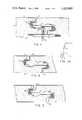
- FIG. 1is a vertical, cross-sectional view of the joint between a pair of like metal skinned foam core panels embodying the principles of my invention and showing an intermediate size gap therebetween and FIG. 1-A is an enlarged, exploded view of parts of FIG. 1;
- FIG. 2is a view similar to FIG. 1 except showing the longitudinally offset sides of the panels in contacting relationship with no gap therebetween;
- FIG. 3is a view similar to FIG. 1 except showing a wide gap between adjoining panels;
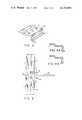
- FIG. 4is an enlarged, top, perspective view of the panel clip 7 shown in FIG. 1;
- FIG. 4-Ais a vertical, cross-sectional view of the clip illustrated in FIG. 4 showing a substantially Z-shaped support;
- FIG. 4-Bis a view similar to FIG. 4-A of a modification showing a sigma shaped support
- FIG. 5shows attached ends of like panels when the end joint occurs at a girt 29 having a narrow flange or mounting surface.
- FIG. 6shows one of the panels of FIG. 1 as it comes from the factory
- FIG. 7shows a vertical cross section of an end joint panel
- FIG. 8shows a modification of the end joint panel embodying the present invention.
- numeral 1denotes an exterior metal skin of steel, aluminum or other suitable metal which partially surrounds and is bonded to a core 2 of plastic foam material such as polyurethane and numeral 3 denotes a spacing or gap between such metal skins of like panels.
- numeral 9denotes an interior metal skin of the panel.
- a pair of like panelsare shown attached together in interlocking relationship by a pair of joints formed by mating portions as shown in FIG. 1. It will be understood that the panel shown at the left of the joint 3 will have a left end construction identical to the left end of the panel shown to the right of the gap 3.
- a multiplicity of like panelsmay be attached together side by side to form a wall of a building, each having exterior metal skins laterally offset from the interior skins.
- the outer metal skin 1is reversely bent so as to form a reservoir 4 as well as a female element for receiving the male element of the panel shown at the right of gap 3.
- the reservoir 4forms a large pocket for receiving sealant 5, being sufficiently sized to maintain a greater aspect ratio, thus retaining resiliency for longer life.
- the size of the sealant pocket and sealantare such as to not to reduce the sealant to extremely thin portions, even when the gap between the adjoining panels becomes extremely small as shown by gap 3a in FIG. 2 since the solvents would otherwise evaporate and the sealant would become dried out and ineffective.
- the larger cavity (4a and 4b) for the sealant 5assures adequate proportions to properly seal the joint whether the gap 3a is closed tightly, as shown in FIG. 2, or whether the joint is held open with a large gap 3b, as shown in FIG. 3, respectively.
- the reservoirallows lateral room for the sealant to flow when the joint is closed tightly, as shown in FIG. 2.
- FIG. 6shows that the sealant is factory applied on the returned flange, 15, just outside of the reservoir area, 4. Then when two panels are engaged, the sealant will be forced to move in the direction of the reservoir. If the joint is wide, the sealant will not enter the reservoir 4b (FIG. 3). If the joint is in the normal position (FIG. 1) the sealant will only partially enter the reservoir. A completely closed joint, as in FIG. 2, will cause the sealant to move into and entirely fill the reservoir 4a.
- the advantage hereis that provision has been made for a complete seal in any of the three positions, but none of the positions squeezes the sealant out of the joint. There is always intimate contact of all metal skins with the sealant; and even in the worst condition, (FIG. 2) there is maintained the correct aspect ratio, i.e., width to height, of the sealant bead.
- the reservoir for the sealantallows greater room for adjustment when the gap must be adjusted to compensate for manufacturing tolerances and for misalignment of the building structure.
- the proper location of the sealantmakes provision for movement due to thermal expansion and contraction over the width of each panel.
- the extreme ends of the outer metal skin 1 and inner metal skin 9are sharply reversely bent to form a hem, such as 14 shown in FIGS. 1 and 1-A.
- the hemmed edges of the metal skinsallow for coil width variation as the metal coils are received from the rolling mills. Standard mill tolerances can be absorbed to assure precise positioning of the finished edges.
- the hemmingalso stiffens the edges, providing greater holding strength for the retaining clips 7, which will be described.
- hem 14 shown at the left of FIG. 2forms an obtuse angle with a horizontal plane which will wipe the sealant into the space provided in the reservoir, rather than squeeze it outwardly toward gap 3a where it would be thinned out and thus become ineffective as a sealant.
- a plastic sheet or edge closure 6is provided for bridging the gap between the hemmed edges 14 of each panel.
- a unique attachment meansis provided in the form of a somewhat U-shaped extruded plastic edge having a bulb or projection 13 which will spread out laterally when moved in the direction of the arrow and then contract and lock against the extremity of the hemmed edge 14 as a stop, as illustrated in FIG. 1, to hold one edge of the plastic sheet on metal skin 1.
- the other edge portion of plastic sheet 6will ride on the hemmed edge of the interior metal skin 9 of the adjoining panel, as shown in FIG. 1.
- a similar closure or plastic sheetis provided between the bottom hemmed edges.
- FIG. 4more clearly shows the shape of the unique clip 7, shown in FIG. 1, having a land offset 23 to provide for head clearance of the fastener screw 8 when the two panels are detachably secured together and fastened to a structural girt 10 as shown in FIG. 1.
- the threaded portion of fastener 8threadedly engages the girt 10 to firmly secure both panels thereto in end-to-end relationship.
- the clip 7may have either a substantially Z-shaped support portion 22, as shown in FIGS. 4 and 4-A, or may have a sigma shaped support as shown in FIG. 4-B which provides somewhat greater columnar strength in cold formed steel.
- the clipis provided with a plurality of holes 21, for example, three holes, thereby permitting it to be used at either end of the panels, especially when an end joint occurs at a girt 29 having a narrow flange or mounting surface, as shown in FIG. 5.
- the upper and lower panelsmeet at horizontal joint 28 and two clips 7,7 are located in close proximity, thereby necessitating either "right hand” and "left had” clips or the use of the same clip with holes at both ends, permitting the identical clip to be located at the upper and lower panels.
- the center holecan be used at girts other than at the end joint.
- the clip 7has a broad bearing surface at the base of the substantially Z or sigma shaped leg to more easily distribute the stresses resulting from negative wind load conditions. This eliminates the tendency to tear the metal skins, which can result when cut edges bear on the inside of the metal skins as occurs in constructions used in the past.
- the present state of the artfavors square cut ends, which are then fitted into an extrusion having essentially an "H" shape.
- the major disadvantages of this systemare: 1. Aesthetically the broad surface of the extrusion is objectional, as it looks like a batten; 2. the extrusion allows through-wall conductance; that is, the cold outside temperature will travel through the batten web into the warm interior surface, permitting condensation and frost build-up.
- FIGS. 7 and 8show an end joint design embodying the present invention.
- the ends of the panelsare factory cut to a special configuration, which provides for a ship-lap type of joint 30.
- a continuous extrusion 31is provided in lengths which are some multiple of the width of the panel.
- the extrusionfits into the ship-lap cut 30 of the lower panel so as to bear on the exposed foam core 32, and completely cover the cut portion.
- the proportions of the bearing surfaceare such that wind loads on the panels will be evenly distributed by the extrusion, which then serves as a mounting clip to support the top of the lower panel.
- Self-tapping screw 33penetrates the extrusion 31, the foam core, and inner metal skin 9, and is secured into the girt 29, to support the top of the lower panel.
- the extrusion 31is deliberately designed to not penetrate through the entire depth of the panel, thereby effectively eliminating through-wall conductivity, which is one of the major objections of the present system.
- the outermost surface 34, of the extrusion 31is of a rather small and inconspicuous proportion so as to eliminate the objectional batten appearance of the earlier joint systems.
- the same surfacecan be painted to match the exterior of the wall panels.
- the bottom ends of the second course of panelsare cut similar to the top of the lower panels. This end is supported by means of the clip 7 previously described. A minor variation on the ship-lap cut on this end is the pocket 35, immediately inside of the exterior skin.
- the exterior skin 1is fitted into the U-shaped slot 36, in the extrusion 31.
- Weep holes 37are predrilled through both vertical legs of the U-shaped slot 36. Rain water cascading down over the face of the panels will enter the U-shaped slot 36, and immediately be conducted out through the outer weep holes 37. Water entering the vertical joint 3, will flow down into the interior wide U-shaped slot 38, and be conducted out through the inner and outer weep holes 37.
- the outer U-channel 36is located so as to have the bottom surface somewhat lower than the bottom of the inner channel 38, thereby preventing a reverse flow of the water.
- the extrusionwill be supplied in convenient lengths, but provision for thermal expansion must be provided in the form of a predetermined gap between the ends of adjacent members. To prevent water infiltration of this gap, a preformed butt strip 39, is supplied, designed to slip into twin slots 40 and 40a on the underside of the extrusion.
Landscapes
- Engineering & Computer Science (AREA)
- Architecture (AREA)
- Civil Engineering (AREA)
- Structural Engineering (AREA)
- Finishing Walls (AREA)
- Building Environments (AREA)
Abstract
Description
Claims (7)
Priority Applications (2)
| Application Number | Priority Date | Filing Date | Title |
|---|---|---|---|
| US05/682,156US4123885A (en) | 1976-04-30 | 1976-04-30 | Building panel joint |
| CA267,199ACA1054769A (en) | 1976-04-30 | 1976-12-05 | Building panel joint |
Applications Claiming Priority (1)
| Application Number | Priority Date | Filing Date | Title |
|---|---|---|---|
| US05/682,156US4123885A (en) | 1976-04-30 | 1976-04-30 | Building panel joint |
Publications (1)
| Publication Number | Publication Date |
|---|---|
| US4123885Atrue US4123885A (en) | 1978-11-07 |
Family
ID=24738472
Family Applications (1)
| Application Number | Title | Priority Date | Filing Date |
|---|---|---|---|
| US05/682,156Expired - LifetimeUS4123885A (en) | 1976-04-30 | 1976-04-30 | Building panel joint |
Country Status (2)
| Country | Link |
|---|---|
| US (1) | US4123885A (en) |
| CA (1) | CA1054769A (en) |
Cited By (49)
| Publication number | Priority date | Publication date | Assignee | Title |
|---|---|---|---|---|
| US4184301A (en)* | 1977-08-27 | 1980-01-22 | H. H. Robertson Company | Fastening device for wall panel joints |
| US4316351A (en)* | 1980-05-27 | 1982-02-23 | Ting Raymond M L | Thermally insulated building construction panel and a wall formed from such panels |
| US4463533A (en)* | 1982-06-24 | 1984-08-07 | Mullet Willis J | Sheet material roofing panel |
| DE3323778A1 (en)* | 1983-07-01 | 1985-01-17 | Hoesch Ag, 4600 Dortmund | WALL OR ROOF ELEMENT MADE OF A FOAM CORE AND METAL COVER LAYERS |
| US4589240A (en)* | 1984-09-19 | 1986-05-20 | Raynor Manufacturing Company | Foam core panel with interlocking skins and thermal break |
| DE3447330A1 (en)* | 1984-12-24 | 1986-07-10 | Hoesch Ag, 4600 Dortmund | WALL OR ROOF ELEMENT MADE OF A FOAM CORE AND METAL COVER LAYERS |
| EP0311738A1 (en)* | 1987-10-16 | 1989-04-19 | Ward Building Systems Limited | Building cladding system |
| EP0286052A3 (en)* | 1987-04-09 | 1989-04-19 | Ward Building Systems Limited | Building cladding system |
| US5277011A (en)* | 1991-07-12 | 1994-01-11 | Serrano Martin Jose A | Watertight roof for buildings and constructions in general |
| US5533312A (en)* | 1994-11-30 | 1996-07-09 | Steel-Craft Door Products Ltd. | Composite panel having interlocked skins and a bonded foam core |
| FR2733264A1 (en)* | 1995-04-18 | 1996-10-25 | Milanese Pierre | Method of assembling cladding panels |
| US5749282A (en)* | 1995-06-29 | 1998-05-12 | United Dominion Industries | Building panel with double interlock joint and internal gutter |
| US5799462A (en)* | 1996-07-02 | 1998-09-01 | Craig McKinney | Method and apparatus for lightweight, insulated, structural building panel systems |
| EP0843056A3 (en)* | 1996-11-13 | 1998-10-07 | Premark RWP Holdings, Inc. | Articles with tongue and groove joint and method of making such a joint |
| WO2000031357A1 (en)* | 1998-11-19 | 2000-06-02 | Centria | Composite joinery |
| US6105314A (en)* | 1996-08-05 | 2000-08-22 | Stocksieker; Richard | Panel system |
| FR2825397A1 (en)* | 2001-06-01 | 2002-12-06 | Tarkett Sommer Sa | FLOOR COVERING ELEMENT (S) |
| US6493975B1 (en)* | 2001-06-29 | 2002-12-17 | Apco Graphics, Inc. | Sign panel with replaceable, frameless-appearing sign face |
| US6634077B2 (en) | 2001-07-20 | 2003-10-21 | Affordable Building Systems | Combined connecting and alignment method for composite fiber building panels |
| US20040134143A1 (en)* | 2003-01-14 | 2004-07-15 | Centria | Features for thin composite architectural panels |
| EP1533442A1 (en) | 2003-11-19 | 2005-05-25 | British Robertson, S.L.U. | External insulating cladding for building facings or roofs |
| US20060156671A1 (en)* | 2005-01-20 | 2006-07-20 | Robert Montague | Apparatus and method for aligning and connecting building panels in close proximity |
| US20060174577A1 (en)* | 2005-01-27 | 2006-08-10 | O'neil John P | Hidden stiffening panel connector and connecting method |
| US20070095094A1 (en)* | 2003-10-31 | 2007-05-03 | Lucas James W | Panel edge joint |
| US20080141607A1 (en)* | 2006-12-13 | 2008-06-19 | Stoecker Gary L | Modular panel system and method |
| US20090025335A1 (en)* | 2006-02-10 | 2009-01-29 | Gregory Flynn | Panel |
| US7748181B1 (en)* | 2006-01-20 | 2010-07-06 | Centria | Advanced building envelope delivery system and method |
| US20100170173A1 (en)* | 2006-01-20 | 2010-07-08 | Centria | Advanced building envelope delivery system and method |
| US20100205883A1 (en)* | 2008-03-04 | 2010-08-19 | Carson Craig D | Method and apparatus for mounting a wall system |
| US8813451B2 (en)* | 2011-07-19 | 2014-08-26 | Red Glaze Group, LLC | Wall attachment clip, wall panel system, and system and method for supporting wall panels |
| US8938927B1 (en)* | 2014-06-18 | 2015-01-27 | McElroy Metal Mill, Inc. | Horizontally oriented insulated metal panel siding system |
| JP2015161092A (en)* | 2014-02-26 | 2015-09-07 | 日鉄住金鋼板株式会社 | Connection structure of sandwich panel |
| JP2016008379A (en)* | 2014-06-20 | 2016-01-18 | 日新製鋼株式会社 | Metal siding |
| CN107327073A (en)* | 2017-08-15 | 2017-11-07 | 多维联合集团有限公司 | A kind of double interlocking splicing type metal curtain wallboard and curtain wall |
| US20180340331A1 (en)* | 2017-05-26 | 2018-11-29 | Duraframe, LLC | Weather resistant temporary wall system and method |
| US20190127989A1 (en)* | 2011-03-18 | 2019-05-02 | Valinge Innovation Ab | Vertical Joint System and Associated Surface Covering System |
| US10329758B2 (en) | 2017-04-24 | 2019-06-25 | Ayo-Ap Corporation | Water draining spandrel assembly and insulated panel window walls |
| US20190309527A1 (en)* | 2016-12-16 | 2019-10-10 | Välinge Innovation AB | A set of decking boards provided with a connecting system |
| US10538922B2 (en) | 2015-01-16 | 2020-01-21 | Ceraloc Innovation Ab | Mechanical locking system for floor panels |
| US10570625B2 (en) | 2014-12-22 | 2020-02-25 | Ceraloc Innovation Ab | Mechanical locking system for floor panels |
| US10794065B2 (en) | 2012-04-04 | 2020-10-06 | Valinge Innovation Ab | Method for producing a mechanical locking system for building panels |
| US11230845B2 (en)* | 2018-02-07 | 2022-01-25 | Kwang Steel Co., Ltd. | Building exterior panel and assembly structure thereof |
| US11326355B2 (en) | 2017-03-16 | 2022-05-10 | Valinge Innovation Ab | Connecting device, support element and connecting system for boards |
| US11377858B2 (en) | 2019-01-08 | 2022-07-05 | Valinge Innovation Ab | Flooring system provided with a connecting system and an associated connecting device |
| US11519183B2 (en) | 2007-11-07 | 2022-12-06 | Valinge Innovation Ab | Mechanical locking of floor panels with vertical snap folding |
| US20230113988A1 (en)* | 2021-10-08 | 2023-04-13 | Nucor Insulated Panel Group LLC., a Nucor Company | Wall panel clip |
| US20230220672A1 (en)* | 2020-03-20 | 2023-07-13 | West.Neder.Land. Sandwich Panelen B.V. | Building panel and coupling system for such building panels |
| US11987990B2 (en) | 2007-11-07 | 2024-05-21 | Välinge Innovation AB | Mechanical locking of floor panels with vertical snap folding |
| US20240344333A1 (en)* | 2021-02-04 | 2024-10-17 | William Kreysler & Associates, Inc. | Weatherproof joint for exterior building panels |
Citations (5)
| Publication number | Priority date | Publication date | Assignee | Title |
|---|---|---|---|---|
| US3667180A (en)* | 1970-11-03 | 1972-06-06 | Robertson Co H H | Fastening means for double-skin foam core building construction panel |
| US3714747A (en)* | 1971-08-23 | 1973-02-06 | Robertson Co H H | Fastening means for double-skin foam core building panel |
| US3777430A (en)* | 1972-08-30 | 1973-12-11 | Robertson Co H H | Complementary mating elements for double-skin foam core panel |
| US3797190A (en)* | 1972-08-10 | 1974-03-19 | Smith E Division Cyclops Corp | Prefabricated, insulated, metal wall panel |
| US3849959A (en)* | 1972-11-14 | 1974-11-26 | Robertson Co H H | Building panel and laterally adjustable joint produced thereby |
- 1976
- 1976-04-30USUS05/682,156patent/US4123885A/ennot_activeExpired - Lifetime
- 1976-12-05CACA267,199Apatent/CA1054769A/ennot_activeExpired
Patent Citations (5)
| Publication number | Priority date | Publication date | Assignee | Title |
|---|---|---|---|---|
| US3667180A (en)* | 1970-11-03 | 1972-06-06 | Robertson Co H H | Fastening means for double-skin foam core building construction panel |
| US3714747A (en)* | 1971-08-23 | 1973-02-06 | Robertson Co H H | Fastening means for double-skin foam core building panel |
| US3797190A (en)* | 1972-08-10 | 1974-03-19 | Smith E Division Cyclops Corp | Prefabricated, insulated, metal wall panel |
| US3777430A (en)* | 1972-08-30 | 1973-12-11 | Robertson Co H H | Complementary mating elements for double-skin foam core panel |
| US3849959A (en)* | 1972-11-14 | 1974-11-26 | Robertson Co H H | Building panel and laterally adjustable joint produced thereby |
Cited By (75)
| Publication number | Priority date | Publication date | Assignee | Title |
|---|---|---|---|---|
| US4184301A (en)* | 1977-08-27 | 1980-01-22 | H. H. Robertson Company | Fastening device for wall panel joints |
| US4316351A (en)* | 1980-05-27 | 1982-02-23 | Ting Raymond M L | Thermally insulated building construction panel and a wall formed from such panels |
| US4463533A (en)* | 1982-06-24 | 1984-08-07 | Mullet Willis J | Sheet material roofing panel |
| DE3323778A1 (en)* | 1983-07-01 | 1985-01-17 | Hoesch Ag, 4600 Dortmund | WALL OR ROOF ELEMENT MADE OF A FOAM CORE AND METAL COVER LAYERS |
| US4589240A (en)* | 1984-09-19 | 1986-05-20 | Raynor Manufacturing Company | Foam core panel with interlocking skins and thermal break |
| DE3447330A1 (en)* | 1984-12-24 | 1986-07-10 | Hoesch Ag, 4600 Dortmund | WALL OR ROOF ELEMENT MADE OF A FOAM CORE AND METAL COVER LAYERS |
| EP0286052A3 (en)* | 1987-04-09 | 1989-04-19 | Ward Building Systems Limited | Building cladding system |
| EP0311738A1 (en)* | 1987-10-16 | 1989-04-19 | Ward Building Systems Limited | Building cladding system |
| US5277011A (en)* | 1991-07-12 | 1994-01-11 | Serrano Martin Jose A | Watertight roof for buildings and constructions in general |
| US5533312A (en)* | 1994-11-30 | 1996-07-09 | Steel-Craft Door Products Ltd. | Composite panel having interlocked skins and a bonded foam core |
| FR2733264A1 (en)* | 1995-04-18 | 1996-10-25 | Milanese Pierre | Method of assembling cladding panels |
| US5749282A (en)* | 1995-06-29 | 1998-05-12 | United Dominion Industries | Building panel with double interlock joint and internal gutter |
| US5799462A (en)* | 1996-07-02 | 1998-09-01 | Craig McKinney | Method and apparatus for lightweight, insulated, structural building panel systems |
| US6105314A (en)* | 1996-08-05 | 2000-08-22 | Stocksieker; Richard | Panel system |
| EP0843056A3 (en)* | 1996-11-13 | 1998-10-07 | Premark RWP Holdings, Inc. | Articles with tongue and groove joint and method of making such a joint |
| US6253511B1 (en) | 1998-11-19 | 2001-07-03 | Centria | Composite joinery |
| US6968659B2 (en) | 1998-11-19 | 2005-11-29 | Centria, Inc. | Composite joinery |
| US6627128B1 (en) | 1998-11-19 | 2003-09-30 | Centria | Composite joinery |
| WO2000031357A1 (en)* | 1998-11-19 | 2000-06-02 | Centria | Composite joinery |
| FR2825397A1 (en)* | 2001-06-01 | 2002-12-06 | Tarkett Sommer Sa | FLOOR COVERING ELEMENT (S) |
| US6493975B1 (en)* | 2001-06-29 | 2002-12-17 | Apco Graphics, Inc. | Sign panel with replaceable, frameless-appearing sign face |
| US6634077B2 (en) | 2001-07-20 | 2003-10-21 | Affordable Building Systems | Combined connecting and alignment method for composite fiber building panels |
| WO2004065715A1 (en)* | 2003-01-14 | 2004-08-05 | Centria | Features for thin composite architectural panels |
| US20040134143A1 (en)* | 2003-01-14 | 2004-07-15 | Centria | Features for thin composite architectural panels |
| US7007433B2 (en)* | 2003-01-14 | 2006-03-07 | Centria | Features for thin composite architectural panels |
| US20070039275A1 (en)* | 2003-01-14 | 2007-02-22 | Keith Boyer | Features for thin composite architectural panels |
| US20070095094A1 (en)* | 2003-10-31 | 2007-05-03 | Lucas James W | Panel edge joint |
| US7694484B2 (en)* | 2003-10-31 | 2010-04-13 | James Walter Lucas | Panel edge joint |
| EP1533442A1 (en) | 2003-11-19 | 2005-05-25 | British Robertson, S.L.U. | External insulating cladding for building facings or roofs |
| ES2302394B2 (en)* | 2003-11-19 | 2009-07-28 | British Robertson, S.L.U. | PANEL WITH MACHIHEMBRATED REMATES FOR FACADES OR COVERS. |
| ES2302394A1 (en)* | 2003-11-19 | 2008-07-01 | British Robertson, S.L.U. | Building cladding system |
| US20060156671A1 (en)* | 2005-01-20 | 2006-07-20 | Robert Montague | Apparatus and method for aligning and connecting building panels in close proximity |
| US20060174577A1 (en)* | 2005-01-27 | 2006-08-10 | O'neil John P | Hidden stiffening panel connector and connecting method |
| US7748181B1 (en)* | 2006-01-20 | 2010-07-06 | Centria | Advanced building envelope delivery system and method |
| US20100170173A1 (en)* | 2006-01-20 | 2010-07-08 | Centria | Advanced building envelope delivery system and method |
| US8631620B2 (en) | 2006-01-20 | 2014-01-21 | Centria | Advanced building envelope delivery system and method |
| US9027301B2 (en) | 2006-01-20 | 2015-05-12 | Centria | Advanced building envelope delivery system and method |
| US20090025335A1 (en)* | 2006-02-10 | 2009-01-29 | Gregory Flynn | Panel |
| US7661235B2 (en)* | 2006-12-13 | 2010-02-16 | Transamerican Strukturoc, Inc. | Modular panel system and method |
| US20080141607A1 (en)* | 2006-12-13 | 2008-06-19 | Stoecker Gary L | Modular panel system and method |
| US20100180542A1 (en)* | 2006-12-13 | 2010-07-22 | Stoecker Gary L | Modular panel system and method |
| US11519183B2 (en) | 2007-11-07 | 2022-12-06 | Valinge Innovation Ab | Mechanical locking of floor panels with vertical snap folding |
| US11987990B2 (en) | 2007-11-07 | 2024-05-21 | Välinge Innovation AB | Mechanical locking of floor panels with vertical snap folding |
| US20100205883A1 (en)* | 2008-03-04 | 2010-08-19 | Carson Craig D | Method and apparatus for mounting a wall system |
| US12139918B2 (en) | 2011-03-18 | 2024-11-12 | Välinge Innovation AB | Vertical joint system and associated surface covering system |
| US10724251B2 (en)* | 2011-03-18 | 2020-07-28 | Valinge Innovation Ab | Vertical joint system and associated surface covering system |
| US11613897B2 (en) | 2011-03-18 | 2023-03-28 | Valinge Innovation Ab | Vertical joint system and associated surface covering system |
| US20190127989A1 (en)* | 2011-03-18 | 2019-05-02 | Valinge Innovation Ab | Vertical Joint System and Associated Surface Covering System |
| US11091920B2 (en) | 2011-03-18 | 2021-08-17 | Valinge Innovation Ab | Vertical joint system and associated surface covering system |
| US9951517B2 (en) | 2011-07-19 | 2018-04-24 | Hgi Resources Llc | Wall attachment clip, wall panel system, and system and method for supporting wall panels |
| US8813451B2 (en)* | 2011-07-19 | 2014-08-26 | Red Glaze Group, LLC | Wall attachment clip, wall panel system, and system and method for supporting wall panels |
| US10794065B2 (en) | 2012-04-04 | 2020-10-06 | Valinge Innovation Ab | Method for producing a mechanical locking system for building panels |
| JP2015161092A (en)* | 2014-02-26 | 2015-09-07 | 日鉄住金鋼板株式会社 | Connection structure of sandwich panel |
| US8938927B1 (en)* | 2014-06-18 | 2015-01-27 | McElroy Metal Mill, Inc. | Horizontally oriented insulated metal panel siding system |
| JP2016008379A (en)* | 2014-06-20 | 2016-01-18 | 日新製鋼株式会社 | Metal siding |
| US10570625B2 (en) | 2014-12-22 | 2020-02-25 | Ceraloc Innovation Ab | Mechanical locking system for floor panels |
| US11913236B2 (en) | 2014-12-22 | 2024-02-27 | Ceraloc Innovation Ab | Mechanical locking system for floor panels |
| US11174646B2 (en) | 2014-12-22 | 2021-11-16 | Ceraloc Innovation Ab | Mechanical locking system for floor panels |
| US11274453B2 (en) | 2015-01-16 | 2022-03-15 | Ceraloc Innovation Ab | Mechanical locking system for floor panels |
| US10538922B2 (en) | 2015-01-16 | 2020-01-21 | Ceraloc Innovation Ab | Mechanical locking system for floor panels |
| US11149444B2 (en)* | 2016-12-16 | 2021-10-19 | Valinge Innovation Ab | Set of decking boards provided with a connecting system |
| US12065840B2 (en) | 2016-12-16 | 2024-08-20 | Välinge Innovation AB | Set of decking boards provided with a connecting system |
| US20190309527A1 (en)* | 2016-12-16 | 2019-10-10 | Välinge Innovation AB | A set of decking boards provided with a connecting system |
| US11326355B2 (en) | 2017-03-16 | 2022-05-10 | Valinge Innovation Ab | Connecting device, support element and connecting system for boards |
| US10329758B2 (en) | 2017-04-24 | 2019-06-25 | Ayo-Ap Corporation | Water draining spandrel assembly and insulated panel window walls |
| US20180340331A1 (en)* | 2017-05-26 | 2018-11-29 | Duraframe, LLC | Weather resistant temporary wall system and method |
| US10501933B2 (en)* | 2017-05-26 | 2019-12-10 | Duraframe, LLC | Weather resistant temporary wall system and method |
| CN107327073A (en)* | 2017-08-15 | 2017-11-07 | 多维联合集团有限公司 | A kind of double interlocking splicing type metal curtain wallboard and curtain wall |
| US11230845B2 (en)* | 2018-02-07 | 2022-01-25 | Kwang Steel Co., Ltd. | Building exterior panel and assembly structure thereof |
| US11377858B2 (en) | 2019-01-08 | 2022-07-05 | Valinge Innovation Ab | Flooring system provided with a connecting system and an associated connecting device |
| US20230220672A1 (en)* | 2020-03-20 | 2023-07-13 | West.Neder.Land. Sandwich Panelen B.V. | Building panel and coupling system for such building panels |
| US12305400B2 (en)* | 2020-04-20 | 2025-05-20 | West.Neder.Land. Sandwich Panelen B.V. | Building panel and coupling system for such building panels |
| US20240344333A1 (en)* | 2021-02-04 | 2024-10-17 | William Kreysler & Associates, Inc. | Weatherproof joint for exterior building panels |
| US12378764B2 (en)* | 2021-02-04 | 2025-08-05 | William Kreysler & Associates, Inc. | Weatherproof joint for exterior building panels |
| US20230113988A1 (en)* | 2021-10-08 | 2023-04-13 | Nucor Insulated Panel Group LLC., a Nucor Company | Wall panel clip |
Also Published As
| Publication number | Publication date |
|---|---|
| CA1054769A (en) | 1979-05-22 |
Similar Documents
| Publication | Publication Date | Title |
|---|---|---|
| US4123885A (en) | Building panel joint | |
| US4184301A (en) | Fastening device for wall panel joints | |
| US5247770A (en) | Exterior composite foam panel wall joint design | |
| US3553918A (en) | Insulated curtain wall construction | |
| US9140008B2 (en) | Multi-layered cladding frame system | |
| US4622794A (en) | Panel wall system | |
| US4506484A (en) | Panel wall system | |
| US4833858A (en) | Apparatus for joining wall panels | |
| US4608793A (en) | Structural gasket wall | |
| US2734602A (en) | dawson | |
| US4196554A (en) | Roof panel joint | |
| USRE40041E1 (en) | Window frame for manufactured housing | |
| US5181360A (en) | Standing-seam roof panel system | |
| CA1171229A (en) | Standing seam roof system | |
| US3323269A (en) | Roofing and siding panel construction with securing means for accommodating differential expansion | |
| US4141188A (en) | Wall construction | |
| US4463533A (en) | Sheet material roofing panel | |
| CA1209860A (en) | Window assembly | |
| US2156347A (en) | Stud and like element | |
| US3129793A (en) | Sunshade panel unit | |
| US3394520A (en) | Interlocking roofing shingle | |
| US3466832A (en) | Structural assembly for use in a building | |
| GB2065744A (en) | Building panels | |
| JPS6011223Y2 (en) | Handrail top surface waterproof structure | |
| GB2125844A (en) | Connecting building panels |
Legal Events
| Date | Code | Title | Description |
|---|---|---|---|
| AS | Assignment | Owner name:MSL ACQUISTION CORPORATION, A DE CORP. Free format text:ASSIGNMENT OF ASSIGNORS INTEREST.;ASSIGNOR:CYCLOPS CORPORATION;REEL/FRAME:004807/0983 Effective date:19870626 Owner name:MSL ACQUISTION CORPORATION, A DE CORP.,STATELESS Free format text:ASSIGNMENT OF ASSIGNORS INTEREST;ASSIGNOR:CYCLOPS CORPORATION;REEL/FRAME:004807/0983 Effective date:19870626 | |
| AS | Assignment | Owner name:MELON BANK, N.A., ONE MELLON BANK CENTER, PITTSBUR Free format text:SECURITY INTEREST;ASSIGNOR:CYCLOPS CORPORATION;REEL/FRAME:004809/0868 Effective date:19870930 | |
| AS | Assignment | Owner name:CYCLOPS CORPORATION Free format text:CHANGE OF NAME;ASSIGNOR:MSL ACQUISITION CORPORATION;REEL/FRAME:004832/0543 Effective date:19880212 | |
| AS | Assignment | Owner name:PITTSBURGH NATIONAL BANK, FIFTH AVENUE AND WOOD ST Free format text:SECURITY INTEREST;ASSIGNOR:CYCLOPS CORPORATION;REEL/FRAME:004994/0581 Effective date:19880727 | |
| AS | Assignment | Owner name:ARMCO INC., OHIO Free format text:SECURITY INTEREST;ASSIGNOR:CYCLOPS CORPORATION;REEL/FRAME:006122/0039 Effective date:19920424 | |
| AS | Assignment | Owner name:CYCLOPS CORPORATION, NEW JERSEY Free format text:RELEASE OF LIEN AND SECURITY INTEREST IN GENERAL INTANGIBLES;ASSIGNOR:PITTSBURGH NATIONAL BANK;REEL/FRAME:006416/0437 Effective date:19920424 | |
| AS | Assignment | Owner name:CYCLOPS CORPORATION, PENNSYLVANIA Free format text:RELEASED BY SECURED PARTY;ASSIGNOR:MELLON BANK, N.A.;REEL/FRAME:006408/0428 Effective date:19930203 | |
| AS | Assignment | Owner name:SMITH STEELITE, PENNSYLVANIA Free format text:ASSIGNMENT OF ASSIGNORS INTEREST.;ASSIGNOR:ARMCO INC.;REEL/FRAME:006435/0071 Effective date:19930211 | |
| STCF | Information on status: patent grant | Free format text:PATENTED FILE - (OLD CASE ADDED FOR FILE TRACKING PURPOSES) | |
| AS | Assignment | Owner name:PNC BANK, NATIONAL ASSOCIATION, PENNSYLVANIA Free format text:SECURITY AGREEMENT;ASSIGNOR:STEELITE, SMITH;REEL/FRAME:008031/0224 Effective date:19960627 | |
| AS | Assignment | Owner name:CENTRIA, PENNSYLVANIA Free format text:CHANGE OF NAME;ASSIGNOR:STEELITE, SMITH;REEL/FRAME:008328/0291 Effective date:19961018 |