US4120302A - Disposable pads for surgical instruments - Google Patents
Disposable pads for surgical instrumentsDownload PDFInfo
- Publication number
- US4120302A US4120302AUS05/730,961US73096176AUS4120302AUS 4120302 AUS4120302 AUS 4120302AUS 73096176 AUS73096176 AUS 73096176AUS 4120302 AUS4120302 AUS 4120302A
- Authority
- US
- United States
- Prior art keywords
- channel
- pad
- jaw
- disposable
- disposable pad
- Prior art date
- Legal status (The legal status is an assumption and is not a legal conclusion. Google has not performed a legal analysis and makes no representation as to the accuracy of the status listed.)
- Expired - Lifetime
Links
Images
Classifications
- A—HUMAN NECESSITIES
- A61—MEDICAL OR VETERINARY SCIENCE; HYGIENE
- A61B—DIAGNOSIS; SURGERY; IDENTIFICATION
- A61B17/00—Surgical instruments, devices or methods
- A61B17/12—Surgical instruments, devices or methods for ligaturing or otherwise compressing tubular parts of the body, e.g. blood vessels or umbilical cord
- A61B17/122—Clamps or clips, e.g. for the umbilical cord
- A—HUMAN NECESSITIES
- A61—MEDICAL OR VETERINARY SCIENCE; HYGIENE
- A61B—DIAGNOSIS; SURGERY; IDENTIFICATION
- A61B17/00—Surgical instruments, devices or methods
- A61B17/28—Surgical forceps
- A61B17/2812—Surgical forceps with a single pivotal connection
- A61B17/282—Jaws
- A—HUMAN NECESSITIES
- A61—MEDICAL OR VETERINARY SCIENCE; HYGIENE
- A61B—DIAGNOSIS; SURGERY; IDENTIFICATION
- A61B17/00—Surgical instruments, devices or methods
- A61B17/28—Surgical forceps
- A61B17/2812—Surgical forceps with a single pivotal connection
- A61B17/282—Jaws
- A61B2017/2825—Inserts of different material in jaws
- A—HUMAN NECESSITIES
- A61—MEDICAL OR VETERINARY SCIENCE; HYGIENE
- A61B—DIAGNOSIS; SURGERY; IDENTIFICATION
- A61B17/00—Surgical instruments, devices or methods
- A61B17/28—Surgical forceps
- A61B17/2812—Surgical forceps with a single pivotal connection
- A61B17/282—Jaws
- A61B2017/2829—Jaws with a removable cover
Definitions
- This inventionrelates to a disposable pad for use with a surgical instrument having a supporting element and more particularly to a disposable pad of the type described for holding an artery or vein or other body tissue without damage.
- a padtypically includes a soft elongated member having some means for attaching the member to each jaw of the clamp.
- the elongated memberpreferably distributes the clamping force uniformly over the surface being held.
- the attachment meansmust therefore be sufficient to support the member securely in place on the jaw of the clamp during use to prevent slippage while at the same time facilitating easy removal of the member after use for disposal.
- the present inventionis directed to a disposable pad for use with a surgical instrument having a supporting element.
- the padincludes a flexible elongated member having a channel therein for slidably receiving the supporting element. Stop means limits longitudinal insertion of the supporting element into the channel, retention means prevents lateral movement of the supporting element out of the channel, and latching means secures the supporting element against longitudinal displacement from the channel.
- the latching meansis normally disposed in a latching position but is shiftable into a releasing position as the elongated member is flexed to bow away from the supporting element.
- the flexible elongated memberWhen the disposable pad is used with a surgical clamp having a pair of elongated jaws which are operatively associated for movement into and out of gripping relation, the flexible elongated member again slidably receives one of the jaws within the channel. Stop means limits longitudinal insertion of the jaw into the channel, retention means prevents lateral movement of the jaw out of the channel, and latching means secures the jaw against longitudinal displacement from the channel.
- the latching meansis again normally disposed in a latching position but is shiftable into a releasing position as the elongated member is flexed to bow away from the jaw.
- the latching meanspreferably includes operatively associated male and female elements.
- the retention meanscan advantageously be defined by at least one bridge member spanning the sides of the channel near its proximal end and preferably a second bridge member spanning the sides of the channel near its distal end.
- the stop meanspreferably includes an end wall member joining the bottom and sides of the channel as well as the second bridge member near its distal end.
- the flexible elongated memberagain slidably receives the hook within the channel. Stop means limits longitudinal insertion of the spring hook into the channel, retention means prevents lateral movement of the hook out of the channel, and latching means secures the hook against longitudinal displacement from the channel.
- the latching meansis again normally disposed in a latching position but is shiftable into a releasing position as the elongated member is flexed to bow away from the hook.
- the latching meanspreferably includes operatively associated male and female elements wherein the male element is a generally wedge-shaped tooth or projection and the female element is a loop.
- the retention meanscan advantageously be defined by at least one tab member extending inwardly from one side of the channel near its proximal end and preferably a second tab member extending inwardly from the other side of the channel toward the first tab member also near its proximal end.
- the stop meanspreferably includes an end wall member joining the bottom and sides of the channel near its distal end.
- the present inventiontherefore retains the advantages inherent in disposable pads while at the same time providing an improved construction that eliminates the problems associated with such pads in the past. It is therefore an object of the present invention to provide a disposable pad for use with a surgical instrument having a supporting element, that effectively precludes damage to arteries, veins, or other body tissues caused by dislocation of the pad during use, wherein the pad is easily attached and removed from the instrument before and after use.
- the provision of the disposable pad and the realization of the advantages to be derived therefromconstitute additional important objects of the present invention with still other objects being appreciated from the details of construction and operation set forth in the accompanying specifications, claims and drawings.
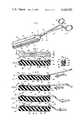
- FIG. 1is a perspective view of a surgical clamp equipped with disposable pads in accordance with the present invention
- FIG. 2is a plan view of one of the disposable pads of FIG. 1 adapted for use with a surgical clamp;
- FIG. 3is a cross-sectional view of the disposable pad of FIG. 2 taken on the line 3--3;
- FIG. 4is a cross-sectional view of the disposable pad of FIG. 3 taken on the line 4--4;
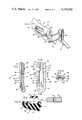
- FIG. 5is a cross-sectional view of one of the disposable pads of FIG. 1 adapted for use with a surgical clamp illustrating a jaw of the clamp being inserted into a channel in the pad;
- FIG. 6is a cross-sectional view of the disposable pad similar to FIG. 5 illustrating the jaw of the clamp being inserted further into the channel in the pad;
- FIG. 7is a cross-sectional view of the disposable pad similar to FIG. 6 illustrating the jaw of the clamp being inserted still further into the channel in the pad;
- FIG. 8is a cross-sectional view of the disposable pad similar to FIG. 7 illustrating the jaw of the clamp fully inserted into the channel in the pad;
- FIG. 9is a fragmentary perspective view of a surgical retractor equipped with a disposable pad in accordance with the present invention.
- FIG. 10is a plan view of the disposable pad of FIG. 9 adapted for use with a surgical retractor
- FIG. 11is a cross-sectional view of the disposable pad of FIG. 10 taken on the line 11--11;
- FIG. 12is a cross-sectional view of the disposable pad of FIG. 10 taken on the line 12--12;
- FIG. 13is a fragmentary cross-sectional view of another form of a disposable pad adapted for use with a surgical clamp illustrating a jaw of the clamp being inserted into a channel in the pad.
- the numeral 10designates generally a pair of disposable pads in accordance with the present invention.
- the pads 10are illustrated in position for use on a pair of supporting elements or jaws 11 and 12 of a surgical clamp 13 which are hinged together as at 14 for movement toward and away from each other.
- the jaw 11is integral with the handle portion 15 and the jaw 12 is integral with the handle portion 16 to provide scissors action for opening and closing the jaws.
- the jaws 11 and 12may be bent as at 17 to a considerable angle relative to the pivotal and handle portions to accommodate the thickness of the pads 10.
- the handles 15 and 16have lugs 18 and 19 equipped with interengaging ratchet teeth to lock the jaws in closed or partially closed positions.
- the lugs 18 and 19are provided remote from the hinge or pivot point 14 adjacent the point where the handles 15 and 16 terminate in finger rings 20 and 21. While the foregoing constitutes a somewhat detailed description of the surgical clamp 13, it has been provided merely to establish an environment for more fully understanding the disposable pads 10 which are actually well suited for use with any surgical instrument having a supporting element.
- the disposable pad 10includes a flexible elongated member 22 having a channel 23 therein (as shown in FIG. 4) for slidably receiving the jaw 11 or 12 of the surgical clamp 13.
- the member 22preferably includes two integrated parts with one of the parts being a cushion 24 and the other of the parts being a member 25 defining the channel 23.
- the channel-defining member 25includes a bottom portion 26 supporting two generally parallel upstanding side portions 27 and 28. The side portions 27 and 28 and the bottom portion 26 are so arranged as to provide the channel 23 with a generally U-shaped cross-section.
- the member 22has a channel 23 as discussed hereinabove which slidably receives the jaw 11 or 12 of the surgical clamp 13. Stop means 29 limits longitudinal insertion of the jaw 11 or 12 into the channel 23, retention means 30 prevents lateral movement of the jaw 11 or 12 out of the channel 23, and latching means 31 secures the jaw 11 or 12 against longitudinal displacement from the channel 23.
- the latching means 31is normally disposed in a latching position (as shown in FIG. 8) but is shiftable into a releasing position (as shown in FIG. 7) as the member 22 is flexed to bow away from the jaw 11 or 12 intermediate its ends.
- the stop means 29is preferably an end wall member (as shown in FIGS. 2 and 8) joining the bottom portion 26 and the side portions 27 and 28 near the distal end of the channel-defining member 25.
- the end wall member 29may be formed integrally with a downwardly-curving extension 32, the extension 32 not only reinforcing the end wall 29 but also serving to control or limit deformation of that portion of the cushion 24 extending beyond the end of the supporting element or jaw 11 or 12.
- the retention means 30is preferably a bridge member 33 (as shown in FIGS. 2 and 8) spanning the side portions 27 and 28 near the proximal end of the channel-defining member 25 with a second bridge member 34 advantageously being provided near the distal end.
- the second bridge member 34joins the upper end of the end wall member 29 as well as spanning the side portions 27 and 28 of the channel-defining member 25.
- the latching means 31(as shown in FIG. 8) includes operatively associated male and female elements.
- the male elementis preferably a pin 35 provided intermediate the ends of the inner surface of the jaw 11 with the female element being a hole 36 (as shown in FIG. 7) provided intermediate the ends of the bottom portion 26 of the channel-defining member 25.
- the latching means 31secures the jaw 11 against longitudinal displacement from the channel 23.
- the means for attaching the disposable pad 10 to the jaw 11 of the surgical clamp 13can be more fully appreciated.
- the tip of the jaw 11, which is narrower and thinner than the portion of the jaw 11 adjacent the bend as at 17,is inserted into the channel 23 under the bridge member 33 (as shown in FIG. 5) and advanced until the pin 35 on the inner surface of the jaw 11 is adjacent the bridge member 33 at the proximal end of the channel 23 (as shown in FIG. 6).
- the jaw 11can easily be inserted to this point because its gradually increasing taper still results in a width and thickness that is less than the width and height of the channel 23 adjacent the bridge member 33.
- the combined thickness of the jaw 11 and the pin 35is slightly less than the height of the channel 23 resulting in some clearance as the portion of the jaw 11 provided with the pin 35 passes under the bridge member 33.
- the jaw 11After the portion of the jaw 11 provided with the pin 35 has passed completely under the bridge member 33, the jaw 11 is inserted further into the channel 23 until the tip of the jaw 11 approaches the second bridge member 34.
- the jaw 11can again easily be inserted to this point because its gradually increasing taper still results in a width and thickness that is less than the width and height of the channel 23 adjacent the bridge member 33.
- the tip of the jaw 11is then forced downwardly into contact with the bottom portion 26 of the channel-defining member 25 (as shown in FIG. 7) with the pin 35 acting as a pivot point causing the member 22 to bow away from the jaw 11 intermediate its ends.
- the jaw 11After forcing the tip of the jaw 11 downwardly into contact with the bottom portion 26 of the channel-defining member 25, the jaw 11 is inserted still further into the channel 23 under the bridge member 34 until the tip of the jaw 11 is in engagement with the end wall member 29 (as shown in FIG. 8). The jaw 11 will be fully inserted at this point with the pin 35 dropping into the hole 36 as the member 22 resumes its normal shape.
- the jaw 11Since the width and height of the channel 23 under the bridge member 34 is generally the same as the width and thickness of the tip of the jaw 11 and the width and height of the channel 23 under the bridge member 33 is generally the same as the width and thickness of the jaw 11 adjacent the bend as at 17, the jaw 11 is snuggly held in position within the channel 23 by the end wall member 29, the bridge members 33 and 34 and the pin 35 disposed in a latching position within the hole 36.
- Stop means 29limits longitudinal insertion of the element into the channel 23
- retention means 30prevents lateral movement of the element out of the channel
- latching means 31secures the element against longitudinal displacement from the channel 23.
- the latching means 31is normally disposed in a latching position but is shiftable into a releasing position as the elongated member 22 is flexed.
- a disposable pad 40(as shown in FIG. 9) is provided for use with a surgical retractor 41 having a pair of arms 42 (only one being shown) each of which carries a hook or blade 43.
- Each hook 43is generally U-shaped in configuration being equipped with a loop portion 44 and legs 45 extending therefrom along the same general plane.
- the legs 45terminate in free end portions 46 which project outwardly from the plane of the legs 45 to be secured within the arm 42.
- the hooks 43are formed of a strong and relatively rigid material such as stainless steel. Further details of typical retractor construction may be obtained from commonly-owned U.S. Pat. No. 2,850,008, it being understood that a retractor is disclosed herein to establish an environment for more fully understanding the disposable pads 40 which are again actually well suited for use with any surgical instrument having a supporting element.
- the disposable pad 40includes a flexible elongated member 47 having a channel 48 therein (as shown in FIG. 12) for slidably receiving the support hook 43 of the surgical retractor 41.
- the member 47preferably includes two integrated parts with one of the parts being a cushion 49 and the other of the parts being a member 50 defining the channel 48.
- the channel-defining member 50includes a bottom portion 51 supporting two upstanding side portions 52 and 53.
- the side portions 52 and 53 and the bottom portion 51are arranged to provide the channel 48 with a generally U-shaped cross-section.
- the side portions 52 and 53are formed (as shown in FIG. 12) so that in production the channel-defining member 50 can be placed into a mold cavity and the cushion 49 can be formed in place about the channel-defining member 50 by using a plastic foam that completely encases the upper ends of the side portions 52 and 53.
- the member 47has a channel 48 as discussed hereinabove which slidably receives the hook 43 of the surgical retractor 41.
- Stop means 54limits longitudinal insertion of the hook 43 into the channel 48
- retention means 55prevents lateral movement of the hook 43 out of the channel 48
- latching means 56secures the hook 43 against longitudinal displacement from the channel 48.
- the latching means 56is normally disposed in a latching position but is shiftable into a releasing position as the member 47 is flexed to bow away from the hook 43 near its distal end.
- the stop means 54is preferably an end wall member (as shown in FIGS. 10 and 11) joining the bottom portion 51 and the side portions 52 and 53 near the distal end of the channel-defining member 50.
- the side portions 57 and 58 of the cushion 49which may extend upwardly beyond the side portions 52 and 53 of the channel-defining member 50 (as shown in FIG. 12) may also join near the distal end of the channel-defining member 50 to further define the end wall member of the stop means 54.
- the end wall member 54is curved to conform to the loop portion 44 of the hook 43 and terminates in a downardly curving extension 59 of the channel-defining member 50 which is also embedded within the plastic foam of the cushion 49.
- the retention means 55is preferably a tab member 60 (as shown in FIG. 10) extending inwardly from one side near the proximal end of the member 47 with a second tab member 61 also advantageously being provided.
- the second tab member 61extends inwardly from the other side near the proximal end of the member 47.
- the latching means 56(as shown in FIG. 9) includes operatively associated male and female elements.
- the male elementis preferably a projection or wedge-shaped tooth 62 provided near the distal end of the bottom portion 51 of the channel-defining member 50 and the female element is defined by the loop portion 44 of the hook 43.
- the latching means 56secures the hook 43 against longitudinal displacement from the channel 48.
- the means for attaching the disposable pad 40 to the support hook 43 of the surgical retractor 41can be more fully appreciated.
- the hook 43is inserted into the channel 48 under the tab members 60 and 61 and advanced until the loop portion 44 is adjacent the wedge-shaped tooth 62 near the distal end of the channel 48.
- the hook 43can easily be inserted to this point because the legs 45 are spaced apart a distance the same as or slightly less than the distance between the side portions 52 and 53 of the channel-defining member 50 and the side portions 57 and 58 of the cushion 49 which serves as guides with nothing to obstruct inward movement.
- the loop portion of the hook 43eventually contacts the wedge-shaped tooth 62 which offers some resistance to further insertion of the hook 43 into the channel-defining member 50.
- the hook 43is inserted further into the channel 48 by urging it inwardly which forces it to ride upwardly on the wedge-shaped tooth 62 causing the member 47 to bow away from the hook 43 near its distal end.
- the loop portion 41will continue to exert a wedging action against the tooth 62 until it clears the tooth 62 and engages the end wall member 54 at which point the tooth 62 will snap into the loop portion 44 as the member 47 resumes its normal position. Since the loop portion 44 is confined within the channel 48 between the end wall member 54 and the wedge-shaped tooth 62 and the legs 45 are confined within the channel 48 by the tab members 60 and 61, the hook 43 is snuggly held in position within the channel-defining member 50.
- the reverse of the above procedurecan be followed.
- the member 47is flexed to bow away from the hook 43 near its distal end sufficiently to disengage the wedge-shaped tooth 62 from the loop portion 44.
- the hook 43is then withdrawn from the channel 48 until the loop portion 44 clears the upper extreme of the wedge-shaped tooth 62 and is further withdrawn causing the loop portion 44 to slide downwardly on the wedge-shaped tooth 62 and outwardly on the bottom portion 51 of the channel-defining member 50.
- the relative sliding movement between the channel 48 and the hook 43is continued until the hook 43 has been fully withdrawn from the channel 48 for disposal of the pad 40.
- Stop means 54limits longitudinal insertion of the element into the channel 48
- retention means 55prevents lateral movement of the element out of the channel
- latching means 56secures the element against longitudinal displacement from the channel 48.
- the latching means 56is normally disposed in a latching position but is shiftable into a releasing position as the elongated member 47 is flexed.
- the latching means(as shown in FIG. 13) includes operatively associated male and female elements but in a somewhat different configuration.
- the latching means of this embodimentis illustrated with a disposable pad 70 that includes a flexible elongated member 71 having a channel 72 therein for slidably receiving a jaw 73 of a surgical clamp.
- the flexible elongated member 71 (partially shown) and the jaw 73 (partially shown)are essentially identical to the flexible elongated member 22 and the jaw 11 (as shown in FIGS. 1 through 8) with the exception of the latching means.
- the flexible elongated member 71preferably includes two integrated parts with one of the parts being a cushion 74 and the other of the parts being a member 75 defining the channel 72.
- the channel-defining member 75has a bottom portion 76 supporting two generally parallel inwardly set upstanding side portions (as shown in FIG. 4) and a bridge member 77 spans the side portions near the proximal end of the channel-defining member 75 to prevent lateral movement of the jaw 73 out of the channel 72.
- the latching meansincludes operatively associated male and female elements normally disposed in a latching position but shiftable into a releasing position as the bridge member portion 77 of the flexible elongated member 71 is flexed to bow away from the jaw 73 near its proximal end.
- the male elementis preferably a pin or nub 78 provided on the undersurface of the bridge member portion 77 with the female element being a hole 79 provided in the jaw 73 near its proximal end.
- the hole 79is positioned so that the pin or nub 78 will engage it when the jaw 73 is fully inserted into the channel 72.
- the latching meanssecures the jaw 73 against longitudinal displacement from the channel 72.
- the means for attaching the disposable pad 70 to the jaw 73 of the surgical clampcan be more fully appreciated.
- the tip of the jaw 73(not shown) narrower and thinner than the portion of the jaw 73 adjacent the bend (not shown), is inserted into the chhanel 72 under the bridge member portion 77 and advanced until the hole 79 in the jaw 73 engages the pin 78.
- the thickness of the jaw 73 in the region of the hole 79is about the same as the height of the channel 72, but the height of the channel 72 under the pin or nub 78 is significantly less than the thickness of the jaw 73 as the jaw 73 passes further under the bridge member portion 77. Therefore, the bridge member portion 77 is gradually forced upward by the taper of the jaw 73 until it snaps back into its original shape when the pin 78 engages the hole 79.
- the tip of the jaw 73approaches a second bridge member (not shown).
- the tip of the jaw 73is then forced downwardly into contact with the bottom portion 76 of the channel-defining member 75 and the jaw 73 is then inserted still further into the channel 72 under the second bridge member until the tip of the jaw 73 is in engagement with the end wall member (not shown).
- the jaw 73will be fully inserted at this point with the pin 78 snapping into the hole 79 as described above.
- the width and height of the channel 72 under the second bridge memberis generally the same as the width and thickness of the tip of the jaw 73 and the width and height of the channel 72 under the bridge member 77 (exclusive of the pin or nub 79) is generally the same as the width and thickness of the jaw 73 adjacent the hole 79, the jaw 73 is snuggly held in position within the channel 72 by the end wall member, the bridge members, and the pin or nub 78 disposed in a latching position within the hole 79.
- the reverse of the above procedurecan be followed.
- the jaw 73is pulled longitudinally from the channel 72 causing the bridge member portion 77 of the flexible elongated member 71 to bow away from the jaw 73 near the proximal end of the member 71 as the pin or nub 78 becomes disengaged from the hole 79.
- a slight taper on the pin 78causes it to ride up out of the hole 79 with the bridge member portion 77 of the flexible elongated member 71 flexing to bring this about or the pin or nub 78 may simply be sheared off by the pulling action.
- the jawis then fully withdrawn from the channel 72 for disposal of the pad 70.
- Stop meanslimits longitudinal insertion of the element into the channel 72
- retention meansprevents lateral movement of the element out of the channel 72
- latching meanssecures the element against longitudinal displacement from the channel 72.
- the latching means 78is normally disposed in a latching position but is shiftable into a releasing position as the bridge member portion 77 of the flexible elongated member 71 is flexed.
- the present inventiontherefore provides pads useful with surgical instruments having a relatively rigid supporting element which are removable and disposable in all of their forms providing a resilient atraumatic cushion for contacting an artery, vein or other body tissue.
- the padscan advantageously be formed of two integrated parts with one of the parts being a channel-defining member formed of resilient plastic and the other of the parts being a cushion formed of a liquid absorbent polyurethane foam. However, they need not be absorbent nor must they be formed of plastic much less a resilient plastic and their surfaces can have teeth, ridges, or other contours depending upon the particular surgical use to which they will be applied.
- the padscan be formed of foam rubber, solid rubber, gauze or textiles, semi-rigid plastics, fluid-filled plastics or other materials as long as they are capable of flexing and it is also possible to form them of a single material throughout especially in the event that a relatively hard construction is desired.
- a unique latching actionoccurs as the relatively rigid supporting element of the surgical instrument is fully inserted into the channel in the disposable pad to secure the pad against inadvertent longitudinal displacement or detachment.
- the unique latching action of the disposable padsis achieved by flexing the pad itself with pairs of male and female elements comprising the latching elements.
- the male elementis provided by a jaw of a surgical clamp whereas the female element is provided by the pad.
- the male elementis provided by the pad whereas the female element is provided by a hook of a retractor.
- the male elementis again provided by the pad whereas the female element is provided by a jaw of a surgical clamp.
- the disposable pads of the present inventionmay be attached to surgical instruments for the purpose of cushioning, fluid absorption, improved traction, or controlled pressure distribution over a desired contact area. Since these pads are commonly supplied as sterile disposables, it is important to have a quick, simple, reliable way of attaching them to the permanent part of the instrument and subsequently removing them for disposal. Several ways of achieving this objective have been developed and used in the past although none of them have been completely effective prior to the present invention which achieves these objectives in a simple yet effective disposable pad having adaptability for use with numerous surgical instruments.
Landscapes
- Health & Medical Sciences (AREA)
- Surgery (AREA)
- Life Sciences & Earth Sciences (AREA)
- Medical Informatics (AREA)
- Animal Behavior & Ethology (AREA)
- Engineering & Computer Science (AREA)
- Biomedical Technology (AREA)
- Heart & Thoracic Surgery (AREA)
- Veterinary Medicine (AREA)
- Molecular Biology (AREA)
- Nuclear Medicine, Radiotherapy & Molecular Imaging (AREA)
- General Health & Medical Sciences (AREA)
- Public Health (AREA)
- Ophthalmology & Optometry (AREA)
- Reproductive Health (AREA)
- Vascular Medicine (AREA)
- Surgical Instruments (AREA)
Abstract
Description
This invention relates to a disposable pad for use with a surgical instrument having a supporting element and more particularly to a disposable pad of the type described for holding an artery or vein or other body tissue without damage.
Disposable pads for use with surgical instruments such as clamps and the advantages to be derived therefrom have previously been disclosed in commonly-owned U.S. Pat. Nos. 3,503,396; 3,503,397; and 3,503,398. A pad typically includes a soft elongated member having some means for attaching the member to each jaw of the clamp. The elongated member preferably distributes the clamping force uniformly over the surface being held. The attachment means must therefore be sufficient to support the member securely in place on the jaw of the clamp during use to prevent slippage while at the same time facilitating easy removal of the member after use for disposal. When such means for attaching the soft elongated member to the jaw of the clamp are subjected to various external forces, however, the disposable pad can become disoriented or disengaged possibly causing damage to the artery or vein or other body tissue being held by the clamp.
While the prior art has dealt with the problems associated with temporarily attaching a disposable pad to a surgical instrument and later removing the pad for disposal with varying degrees of success, the present invention represents an improvement over all such prior art constructions.
The present invention is directed to a disposable pad for use with a surgical instrument having a supporting element. The pad includes a flexible elongated member having a channel therein for slidably receiving the supporting element. Stop means limits longitudinal insertion of the supporting element into the channel, retention means prevents lateral movement of the supporting element out of the channel, and latching means secures the supporting element against longitudinal displacement from the channel. The latching means is normally disposed in a latching position but is shiftable into a releasing position as the elongated member is flexed to bow away from the supporting element.
When the disposable pad is used with a surgical clamp having a pair of elongated jaws which are operatively associated for movement into and out of gripping relation, the flexible elongated member again slidably receives one of the jaws within the channel. Stop means limits longitudinal insertion of the jaw into the channel, retention means prevents lateral movement of the jaw out of the channel, and latching means secures the jaw against longitudinal displacement from the channel. The latching means is again normally disposed in a latching position but is shiftable into a releasing position as the elongated member is flexed to bow away from the jaw.
The latching means preferably includes operatively associated male and female elements. The retention means can advantageously be defined by at least one bridge member spanning the sides of the channel near its proximal end and preferably a second bridge member spanning the sides of the channel near its distal end. The stop means preferably includes an end wall member joining the bottom and sides of the channel as well as the second bridge member near its distal end.
When the removable pad is used with a retractor having at least one arm carrying a hook, the flexible elongated member again slidably receives the hook within the channel. Stop means limits longitudinal insertion of the spring hook into the channel, retention means prevents lateral movement of the hook out of the channel, and latching means secures the hook against longitudinal displacement from the channel. The latching means is again normally disposed in a latching position but is shiftable into a releasing position as the elongated member is flexed to bow away from the hook.
The latching means preferably includes operatively associated male and female elements wherein the male element is a generally wedge-shaped tooth or projection and the female element is a loop. The retention means can advantageously be defined by at least one tab member extending inwardly from one side of the channel near its proximal end and preferably a second tab member extending inwardly from the other side of the channel toward the first tab member also near its proximal end. The stop means preferably includes an end wall member joining the bottom and sides of the channel near its distal end.
The present invention therefore retains the advantages inherent in disposable pads while at the same time providing an improved construction that eliminates the problems associated with such pads in the past. It is therefore an object of the present invention to provide a disposable pad for use with a surgical instrument having a supporting element, that effectively precludes damage to arteries, veins, or other body tissues caused by dislocation of the pad during use, wherein the pad is easily attached and removed from the instrument before and after use. The provision of the disposable pad and the realization of the advantages to be derived therefrom constitute additional important objects of the present invention with still other objects being appreciated from the details of construction and operation set forth in the accompanying specifications, claims and drawings.
The invention is described in conjunction with the accompanying drawings in which:
FIG. 1 is a perspective view of a surgical clamp equipped with disposable pads in accordance with the present invention;
FIG. 2 is a plan view of one of the disposable pads of FIG. 1 adapted for use with a surgical clamp;
FIG. 3 is a cross-sectional view of the disposable pad of FIG. 2 taken on theline 3--3;
FIG. 4 is a cross-sectional view of the disposable pad of FIG. 3 taken on theline 4--4;
FIG. 5 is a cross-sectional view of one of the disposable pads of FIG. 1 adapted for use with a surgical clamp illustrating a jaw of the clamp being inserted into a channel in the pad;
FIG. 6 is a cross-sectional view of the disposable pad similar to FIG. 5 illustrating the jaw of the clamp being inserted further into the channel in the pad;
FIG. 7 is a cross-sectional view of the disposable pad similar to FIG. 6 illustrating the jaw of the clamp being inserted still further into the channel in the pad;
FIG. 8 is a cross-sectional view of the disposable pad similar to FIG. 7 illustrating the jaw of the clamp fully inserted into the channel in the pad;
FIG. 9 is a fragmentary perspective view of a surgical retractor equipped with a disposable pad in accordance with the present invention;
FIG. 10 is a plan view of the disposable pad of FIG. 9 adapted for use with a surgical retractor;
FIG. 11 is a cross-sectional view of the disposable pad of FIG. 10 taken on the line 11--11;
FIG. 12 is a cross-sectional view of the disposable pad of FIG. 10 taken on theline 12--12; and
FIG. 13 is a fragmentary cross-sectional view of another form of a disposable pad adapted for use with a surgical clamp illustrating a jaw of the clamp being inserted into a channel in the pad.
In the illustration given and with reference first to FIG. 1, thenumeral 10 designates generally a pair of disposable pads in accordance with the present invention. Thepads 10 are illustrated in position for use on a pair of supporting elements orjaws 11 and 12 of asurgical clamp 13 which are hinged together as at 14 for movement toward and away from each other. The jaw 11 is integral with thehandle portion 15 and thejaw 12 is integral with thehandle portion 16 to provide scissors action for opening and closing the jaws. Thejaws 11 and 12 may be bent as at 17 to a considerable angle relative to the pivotal and handle portions to accommodate the thickness of thepads 10. Thehandles lugs lugs pivot point 14 adjacent the point where thehandles finger rings surgical clamp 13, it has been provided merely to establish an environment for more fully understanding thedisposable pads 10 which are actually well suited for use with any surgical instrument having a supporting element.
Thedisposable pad 10 includes a flexibleelongated member 22 having achannel 23 therein (as shown in FIG. 4) for slidably receiving thejaw 11 or 12 of thesurgical clamp 13. Themember 22 preferably includes two integrated parts with one of the parts being acushion 24 and the other of the parts being amember 25 defining thechannel 23. The channel-definingmember 25 includes abottom portion 26 supporting two generally parallelupstanding side portions side portions bottom portion 26 are so arranged as to provide thechannel 23 with a generally U-shaped cross-section.
Themember 22 has achannel 23 as discussed hereinabove which slidably receives thejaw 11 or 12 of thesurgical clamp 13. Stop means 29 limits longitudinal insertion of thejaw 11 or 12 into thechannel 23, retention means 30 prevents lateral movement of thejaw 11 or 12 out of thechannel 23, and latching means 31 secures thejaw 11 or 12 against longitudinal displacement from thechannel 23. Thelatching means 31 is normally disposed in a latching position (as shown in FIG. 8) but is shiftable into a releasing position (as shown in FIG. 7) as themember 22 is flexed to bow away from thejaw 11 or 12 intermediate its ends.
The stop means 29 is preferably an end wall member (as shown in FIGS. 2 and 8) joining thebottom portion 26 and theside portions member 25. Theend wall member 29 may be formed integrally with a downwardly-curvingextension 32, theextension 32 not only reinforcing theend wall 29 but also serving to control or limit deformation of that portion of thecushion 24 extending beyond the end of the supporting element orjaw 11 or 12.
The retention means 30 is preferably a bridge member 33 (as shown in FIGS. 2 and 8) spanning theside portions member 25 with asecond bridge member 34 advantageously being provided near the distal end. Thesecond bridge member 34 joins the upper end of theend wall member 29 as well as spanning theside portions member 25. When thejaw 11 or 12 has been longitudinally inserted into thechannel 23 with the tip of the jaw in contact with theend wall member 29, thebridge members jaw 11 or 12 out of thechannel 23.
The latching means 31 (as shown in FIG. 8) includes operatively associated male and female elements. The male element is preferably apin 35 provided intermediate the ends of the inner surface of the jaw 11 with the female element being a hole 36 (as shown in FIG. 7) provided intermediate the ends of thebottom portion 26 of the channel-definingmember 25. When thepin 35 is disposed within thehole 36, the latching means 31 secures the jaw 11 against longitudinal displacement from thechannel 23.
Referring to FIGS. 5 through 8, the means for attaching thedisposable pad 10 to the jaw 11 of thesurgical clamp 13 can be more fully appreciated. The tip of the jaw 11, which is narrower and thinner than the portion of the jaw 11 adjacent the bend as at 17, is inserted into thechannel 23 under the bridge member 33 (as shown in FIG. 5) and advanced until thepin 35 on the inner surface of the jaw 11 is adjacent thebridge member 33 at the proximal end of the channel 23 (as shown in FIG. 6). The jaw 11 can easily be inserted to this point because its gradually increasing taper still results in a width and thickness that is less than the width and height of thechannel 23 adjacent thebridge member 33. The combined thickness of the jaw 11 and thepin 35 is slightly less than the height of thechannel 23 resulting in some clearance as the portion of the jaw 11 provided with thepin 35 passes under thebridge member 33.
After the portion of the jaw 11 provided with thepin 35 has passed completely under thebridge member 33, the jaw 11 is inserted further into thechannel 23 until the tip of the jaw 11 approaches thesecond bridge member 34. The jaw 11 can again easily be inserted to this point because its gradually increasing taper still results in a width and thickness that is less than the width and height of thechannel 23 adjacent thebridge member 33. The tip of the jaw 11 is then forced downwardly into contact with thebottom portion 26 of the channel-defining member 25 (as shown in FIG. 7) with thepin 35 acting as a pivot point causing themember 22 to bow away from the jaw 11 intermediate its ends.
After forcing the tip of the jaw 11 downwardly into contact with thebottom portion 26 of the channel-definingmember 25, the jaw 11 is inserted still further into thechannel 23 under thebridge member 34 until the tip of the jaw 11 is in engagement with the end wall member 29 (as shown in FIG. 8). The jaw 11 will be fully inserted at this point with thepin 35 dropping into thehole 36 as themember 22 resumes its normal shape. Since the width and height of thechannel 23 under thebridge member 34 is generally the same as the width and thickness of the tip of the jaw 11 and the width and height of thechannel 23 under thebridge member 33 is generally the same as the width and thickness of the jaw 11 adjacent the bend as at 17, the jaw 11 is snuggly held in position within thechannel 23 by theend wall member 29, thebridge members pin 35 disposed in a latching position within thehole 36.
When it is later desired to remove the jaw 11 from thechannel 23, the reverse of the above procedure can be followed. Themember 22 is flexed (as shown in FIG. 7) to bow away from the jaw 11 intermediate its ends sufficiently to disengage thepin 35 from thehole 36. The jaw 11 is then withdrawn from thechannel 23.
With the above construction, a quick, effective and reliable means for attaching adisposable pad 10 to the supporting element of a surgical instrument is provided. Stop means 29 limits longitudinal insertion of the element into thechannel 23, retention means 30 prevents lateral movement of the element out of the channel, and latching means 31 secures the element against longitudinal displacement from thechannel 23. The latching means 31 is normally disposed in a latching position but is shiftable into a releasing position as theelongated member 22 is flexed.
In another form of the invention, a disposable pad 40 (as shown in FIG. 9) is provided for use with asurgical retractor 41 having a pair of arms 42 (only one being shown) each of which carries a hook orblade 43. Eachhook 43 is generally U-shaped in configuration being equipped with aloop portion 44 andlegs 45 extending therefrom along the same general plane. Thelegs 45 terminate infree end portions 46 which project outwardly from the plane of thelegs 45 to be secured within thearm 42. Thehooks 43 are formed of a strong and relatively rigid material such as stainless steel. Further details of typical retractor construction may be obtained from commonly-owned U.S. Pat. No. 2,850,008, it being understood that a retractor is disclosed herein to establish an environment for more fully understanding thedisposable pads 40 which are again actually well suited for use with any surgical instrument having a supporting element.
Thedisposable pad 40 includes a flexibleelongated member 47 having achannel 48 therein (as shown in FIG. 12) for slidably receiving thesupport hook 43 of thesurgical retractor 41. Themember 47 preferably includes two integrated parts with one of the parts being acushion 49 and the other of the parts being amember 50 defining thechannel 48. The channel-definingmember 50 includes abottom portion 51 supporting twoupstanding side portions side portions bottom portion 51 are arranged to provide thechannel 48 with a generally U-shaped cross-section. Theside portions member 50 can be placed into a mold cavity and thecushion 49 can be formed in place about the channel-definingmember 50 by using a plastic foam that completely encases the upper ends of theside portions
Themember 47 has achannel 48 as discussed hereinabove which slidably receives thehook 43 of thesurgical retractor 41. Stop means 54 limits longitudinal insertion of thehook 43 into thechannel 48, retention means 55 prevents lateral movement of thehook 43 out of thechannel 48, and latching means 56 secures thehook 43 against longitudinal displacement from thechannel 48. The latching means 56 is normally disposed in a latching position but is shiftable into a releasing position as themember 47 is flexed to bow away from thehook 43 near its distal end.
The stop means 54 is preferably an end wall member (as shown in FIGS. 10 and 11) joining thebottom portion 51 and theside portions member 50. Theside portions cushion 49 which may extend upwardly beyond theside portions member 50 to further define the end wall member of the stop means 54. Theend wall member 54 is curved to conform to theloop portion 44 of thehook 43 and terminates in adownardly curving extension 59 of the channel-definingmember 50 which is also embedded within the plastic foam of thecushion 49.
The retention means 55 is preferably a tab member 60 (as shown in FIG. 10) extending inwardly from one side near the proximal end of themember 47 with asecond tab member 61 also advantageously being provided. Thesecond tab member 61 extends inwardly from the other side near the proximal end of themember 47. When thehook 43 has been longitudinally inserted into thechannel 48 with theloop portion 44 in contact with theend wall member 54, thetab members hook 43 from thechannel 48.
The latching means 56 (as shown in FIG. 9) includes operatively associated male and female elements. The male element is preferably a projection or wedge-shapedtooth 62 provided near the distal end of thebottom portion 51 of the channel-definingmember 50 and the female element is defined by theloop portion 44 of thehook 43. When the wedge-shapedtooth 62 is disposed within theloop portion 44, the latching means 56 secures thehook 43 against longitudinal displacement from thechannel 48.
Referring to FIG. 9, the means for attaching thedisposable pad 40 to thesupport hook 43 of thesurgical retractor 41 can be more fully appreciated. Thehook 43 is inserted into thechannel 48 under thetab members loop portion 44 is adjacent the wedge-shapedtooth 62 near the distal end of thechannel 48. Thehook 43 can easily be inserted to this point because thelegs 45 are spaced apart a distance the same as or slightly less than the distance between theside portions member 50 and theside portions cushion 49 which serves as guides with nothing to obstruct inward movement. However, the loop portion of thehook 43 eventually contacts the wedge-shapedtooth 62 which offers some resistance to further insertion of thehook 43 into the channel-definingmember 50.
After theloop portion 44 has made contact with the wedge-shapedtooth 62, thehook 43 is inserted further into thechannel 48 by urging it inwardly which forces it to ride upwardly on the wedge-shapedtooth 62 causing themember 47 to bow away from thehook 43 near its distal end. Theloop portion 41 will continue to exert a wedging action against thetooth 62 until it clears thetooth 62 and engages theend wall member 54 at which point thetooth 62 will snap into theloop portion 44 as themember 47 resumes its normal position. Since theloop portion 44 is confined within thechannel 48 between theend wall member 54 and the wedge-shapedtooth 62 and thelegs 45 are confined within thechannel 48 by thetab members hook 43 is snuggly held in position within the channel-definingmember 50.
When it is later desired to remove thehook 43 from thechannel 48, the reverse of the above procedure can be followed. Themember 47 is flexed to bow away from thehook 43 near its distal end sufficiently to disengage the wedge-shapedtooth 62 from theloop portion 44. Thehook 43 is then withdrawn from thechannel 48 until theloop portion 44 clears the upper extreme of the wedge-shapedtooth 62 and is further withdrawn causing theloop portion 44 to slide downwardly on the wedge-shapedtooth 62 and outwardly on thebottom portion 51 of the channel-definingmember 50. The relative sliding movement between thechannel 48 and thehook 43 is continued until thehook 43 has been fully withdrawn from thechannel 48 for disposal of thepad 40.
With this alternative construction, another quick, effective and reliable means for attaching adisposable pad 40 to the supporting element of a surgical instrument is provided. Stop means 54 limits longitudinal insertion of the element into thechannel 48, retention means 55 prevents lateral movement of the element out of the channel and latching means 56 secures the element against longitudinal displacement from thechannel 48. The latching means 56 is normally disposed in a latching position but is shiftable into a releasing position as theelongated member 47 is flexed.
In still another form of the invention useful with surgical clamps such as the one illustrated in FIGS. 1 through 8, the latching means (as shown in FIG. 13) includes operatively associated male and female elements but in a somewhat different configuration. The latching means of this embodiment is illustrated with adisposable pad 70 that includes a flexibleelongated member 71 having achannel 72 therein for slidably receiving ajaw 73 of a surgical clamp. It should be noted that the flexible elongated member 71 (partially shown) and the jaw 73 (partially shown) are essentially identical to the flexibleelongated member 22 and the jaw 11 (as shown in FIGS. 1 through 8) with the exception of the latching means. The flexibleelongated member 71 preferably includes two integrated parts with one of the parts being acushion 74 and the other of the parts being amember 75 defining thechannel 72. The channel-definingmember 75 has abottom portion 76 supporting two generally parallel inwardly set upstanding side portions (as shown in FIG. 4) and abridge member 77 spans the side portions near the proximal end of the channel-definingmember 75 to prevent lateral movement of thejaw 73 out of thechannel 72. With respect to other structural details of the form of the invention illustrated in FIG. 13, apart from the latching means to be described hereinafter, reference may be made to the description of the embodiment illustrated in FIGS. 1 through 8 hereinabove.
The latching means includes operatively associated male and female elements normally disposed in a latching position but shiftable into a releasing position as thebridge member portion 77 of the flexibleelongated member 71 is flexed to bow away from thejaw 73 near its proximal end. The male element is preferably a pin ornub 78 provided on the undersurface of thebridge member portion 77 with the female element being ahole 79 provided in thejaw 73 near its proximal end. Thehole 79 is positioned so that the pin ornub 78 will engage it when thejaw 73 is fully inserted into thechannel 72. When the pin ornub 78 is disposed within thehole 79, the latching means secures thejaw 73 against longitudinal displacement from thechannel 72.
Referring to FIG. 13, the means for attaching thedisposable pad 70 to thejaw 73 of the surgical clamp can be more fully appreciated. The tip of the jaw 73 (not shown) narrower and thinner than the portion of thejaw 73 adjacent the bend (not shown), is inserted into thechhanel 72 under thebridge member portion 77 and advanced until thehole 79 in thejaw 73 engages thepin 78. The thickness of thejaw 73 in the region of thehole 79 is about the same as the height of thechannel 72, but the height of thechannel 72 under the pin ornub 78 is significantly less than the thickness of thejaw 73 as thejaw 73 passes further under thebridge member portion 77. Therefore, thebridge member portion 77 is gradually forced upward by the taper of thejaw 73 until it snaps back into its original shape when thepin 78 engages thehole 79.
As thejaw 73 is inserted into thechannel 72, the tip of thejaw 73 approaches a second bridge member (not shown). The tip of thejaw 73 is then forced downwardly into contact with thebottom portion 76 of the channel-definingmember 75 and thejaw 73 is then inserted still further into thechannel 72 under the second bridge member until the tip of thejaw 73 is in engagement with the end wall member (not shown). Thejaw 73 will be fully inserted at this point with thepin 78 snapping into thehole 79 as described above. Since the width and height of thechannel 72 under the second bridge member is generally the same as the width and thickness of the tip of thejaw 73 and the width and height of thechannel 72 under the bridge member 77 (exclusive of the pin or nub 79) is generally the same as the width and thickness of thejaw 73 adjacent thehole 79, thejaw 73 is snuggly held in position within thechannel 72 by the end wall member, the bridge members, and the pin ornub 78 disposed in a latching position within thehole 79.
When it is later desired to remove thejaw 73 from thechannel 72, the reverse of the above procedure can be followed. Thejaw 73 is pulled longitudinally from thechannel 72 causing thebridge member portion 77 of the flexibleelongated member 71 to bow away from thejaw 73 near the proximal end of themember 71 as the pin ornub 78 becomes disengaged from thehole 79. A slight taper on thepin 78 causes it to ride up out of thehole 79 with thebridge member portion 77 of the flexibleelongated member 71 flexing to bring this about or the pin ornub 78 may simply be sheared off by the pulling action. The jaw is then fully withdrawn from thechannel 72 for disposal of thepad 70.
With this additional alternative construction, still another quick, effective and reliable means for attaching adisposable pad 70 to the supporting element of a surgical instrument is provided. Stop means limits longitudinal insertion of the element into thechannel 72, retention means prevents lateral movement of the element out of thechannel 72, and latching means secures the element against longitudinal displacement from thechannel 72. The latching means 78 is normally disposed in a latching position but is shiftable into a releasing position as thebridge member portion 77 of the flexibleelongated member 71 is flexed.
The present invention therefore provides pads useful with surgical instruments having a relatively rigid supporting element which are removable and disposable in all of their forms providing a resilient atraumatic cushion for contacting an artery, vein or other body tissue. The pads can advantageously be formed of two integrated parts with one of the parts being a channel-defining member formed of resilient plastic and the other of the parts being a cushion formed of a liquid absorbent polyurethane foam. However, they need not be absorbent nor must they be formed of plastic much less a resilient plastic and their surfaces can have teeth, ridges, or other contours depending upon the particular surgical use to which they will be applied. The pads can be formed of foam rubber, solid rubber, gauze or textiles, semi-rigid plastics, fluid-filled plastics or other materials as long as they are capable of flexing and it is also possible to form them of a single material throughout especially in the event that a relatively hard construction is desired. With the present invention, a unique latching action occurs as the relatively rigid supporting element of the surgical instrument is fully inserted into the channel in the disposable pad to secure the pad against inadvertent longitudinal displacement or detachment.
The unique latching action of the disposable pads is achieved by flexing the pad itself with pairs of male and female elements comprising the latching elements. In the first embodiment (FIGS. 1 through 8), the male element is provided by a jaw of a surgical clamp whereas the female element is provided by the pad. In the second embodiment (FIGS. 9 through 12), the male element is provided by the pad whereas the female element is provided by a hook of a retractor. In the third embodiment (FIG. 13), the male element is again provided by the pad whereas the female element is provided by a jaw of a surgical clamp. With all three embodiments, the disposable pads which are, in most instances, even more firmly secured in a latching position during use must flex to engage and disengage the pairs of male and female elements comprising the latching elements.
The disposable pads of the present invention may be attached to surgical instruments for the purpose of cushioning, fluid absorption, improved traction, or controlled pressure distribution over a desired contact area. Since these pads are commonly supplied as sterile disposables, it is important to have a quick, simple, reliable way of attaching them to the permanent part of the instrument and subsequently removing them for disposal. Several ways of achieving this objective have been developed and used in the past although none of them have been completely effective prior to the present invention which achieves these objectives in a simple yet effective disposable pad having adaptability for use with numerous surgical instruments.
While in the foregoing specification a detailed description of the invention has been set forth for purposes of illustration, variation of the details herein given may be made by those skilled in the art without departing from the spirit and scope of the invention.
Claims (13)
1. A disposable pad for use with a surgical instrument comprising a resilient flexible elongated member of generally U-shaped cross sectional configuration having proximal and distal ends and having an open-sided channel therein for slidably receiving a supporting element of said instrument, stop means provided by said pad adjacent said distal end for limiting the longitudinal insertion of said element into said channel from the proximal end of said member, retention means for preventing transverse movement of said element out of said channel, said retention means being located adjacent the proximal end of said flexible elongated member and completely bridging said channel, and latching means provided by said member for securing said element against longitudinal displacement from said channel, said latching means normally being disposed in a latching position but being shiftable into a releasing position as said elongated member is flexed.
2. The disposable pad of claim 1 in which said flexible elongated member includes two integrated parts with one of said parts being a resilient plastic foam cushion and the other of said parts being a flexible member defining said channel.
3. The disposable pad of claim 2 in which said channel-defining member is formed of a resilient plastic.
4. The disposable pad of claim 1 in which said retention means includes a bridge member completely spanning said channel adjacent the proximal end of said flexible member.
5. The disposable pad of claim 1 in which second retention means is provided by said pad and includes a second bridge member completely spanning said channel adjacent the distal end of said flexible member.
6. The disposable pad of claim 1 in which said stop means includes an end wall member joining the bottom and sides of said channel-defining member near its distal end.
7. The disposable pad of claim 5 in which said end wall member and said bridge members are integral with said channel-defining member.
8. The disposable pad of claim 1 in which said latching means includes one element of a pair of operatively associated male and female elements, the other of said elements being provided by said surgical instrument.
9. The disposable pad of claim 8 in which said one element is provided intermediate the ends of said channel-defining member and within said channel.
10. The disposable pad of claim 9 in which said one element is a pin projecting from said member within said channel at an intermediate point spaced between said proximal and distal ends.
11. A disposable pad and surgical clamp combination, said surgical clamp having a pair of elongated jaws operatively associated for movement into and out of gripping relation, said pad comprising a resilient flexible elongated member of generally U-shaped cross section having proximal and distal ends and having an open-sided channel therein for slidably receiving one of said jaws, stop means provided by said pad adjacent said distal end for limiting the longitudinal insertion of said jaw into said channel from the proximal end thereof, retention means provided by said member adjacent said proximal end and completely spanning said channel at its proximal end for preventing complete transverse movement of said jaw out of said channel, and latching means for securing said jaw against longitudinal displacement from said channel, said latching means including operatively associated male and female elements provided by said jaw and pad intermediate the length thereof and normally disposed in a latching position but shiftable into a releasing position when an intermediate portion of said channel-defining member is flexed to bow away from said jaw to separate said male and female elements.
12. The structure of claim 1 in which said male element is provided by said pad and said female element by said jaw.
13. The structure of claim 11 in which said retention means is a bridge member formed integrally with said pad and completely spanning said channel at said proximal end.
Priority Applications (1)
| Application Number | Priority Date | Filing Date | Title |
|---|---|---|---|
| US05/730,961US4120302A (en) | 1976-10-08 | 1976-10-08 | Disposable pads for surgical instruments |
Applications Claiming Priority (1)
| Application Number | Priority Date | Filing Date | Title |
|---|---|---|---|
| US05/730,961US4120302A (en) | 1976-10-08 | 1976-10-08 | Disposable pads for surgical instruments |
Publications (1)
| Publication Number | Publication Date |
|---|---|
| US4120302Atrue US4120302A (en) | 1978-10-17 |
Family
ID=24937501
Family Applications (1)
| Application Number | Title | Priority Date | Filing Date |
|---|---|---|---|
| US05/730,961Expired - LifetimeUS4120302A (en) | 1976-10-08 | 1976-10-08 | Disposable pads for surgical instruments |
Country Status (1)
| Country | Link |
|---|---|
| US (1) | US4120302A (en) |
Cited By (108)
| Publication number | Priority date | Publication date | Assignee | Title |
|---|---|---|---|---|
| US4397311A (en)* | 1979-12-20 | 1983-08-09 | Vesesojuzny Nauchnoissledovatelsky I Ispytatelny Institut | Surgical instrument for staple suturing of hollow organs |
| US4526172A (en)* | 1983-08-25 | 1985-07-02 | Premium Plastics, Inc. | One piece multi-purpose clamp |
| US4611592A (en)* | 1983-08-05 | 1986-09-16 | Talboy Glenn E | Clamp for holding surgical lines |
| US4634165A (en)* | 1985-01-17 | 1987-01-06 | Russell Robert C | Forceps having replaceable tips |
| US4666451A (en)* | 1986-06-16 | 1987-05-19 | Samaria Carlos E E | Clamp to be actuated by a hand prothesis |
| US4667671A (en)* | 1985-11-15 | 1987-05-26 | Danzig Fred G | Apparatus for ligating blood vessels, nerves and other anatomical structures |
| US4924864A (en)* | 1985-11-15 | 1990-05-15 | Danzig Fred G | Apparatus and article for ligating blood vessels, nerves and other anatomical structures |
| US4930932A (en)* | 1989-03-29 | 1990-06-05 | Minnesota Scientific, Inc. | Quick release attachment mechanism |
| USD319877S (en) | 1989-01-12 | 1991-09-10 | R. Martin Oliveras | Gynecological forceps |
| EP0490301A1 (en)* | 1990-12-10 | 1992-06-17 | Krishna M. Jain | Surgical clamp jaw cover |
| US5242458A (en)* | 1991-10-15 | 1993-09-07 | Ethicon, Inc. | Suture needle holder for endoscopic use |
| EP0598607A3 (en)* | 1992-11-18 | 1995-04-05 | Ethicon Inc | Atraumatic endoscopic instrument. |
| WO1996003099A1 (en)* | 1994-07-22 | 1996-02-08 | Mark Daniel Sheldon | Device for manipulating or holding delicate objects |
| US5569298A (en)* | 1994-05-02 | 1996-10-29 | Schnell; William J. | Resposable scissors |
| US5591182A (en)* | 1994-10-17 | 1997-01-07 | Applied Medical Resources Corporation | Atraumatic surgical clamping instrument |
| WO1999011179A1 (en)* | 1997-09-04 | 1999-03-11 | Applied Medical Resources Corporation | Surgical clamp with improved traction |
| EP0906061A4 (en)* | 1996-04-17 | 1999-05-19 | ||
| US6206896B1 (en)* | 1998-07-27 | 2001-03-27 | Thomas J. Fogarty | Surgical clamp pad with interdigitating teeth |
| US6228104B1 (en) | 1999-06-18 | 2001-05-08 | Novare Surgical Systems, Inc. | Surgical clamp having replaceable pad |
| US6273902B1 (en) | 1999-06-18 | 2001-08-14 | Novare Surgical Systems, Inc. | Surgical clamp having replaceable pad |
| US6387112B1 (en) | 1999-06-18 | 2002-05-14 | Novare Surgical Systems, Inc. | Surgical clamp having replaceable pad |
| US20020124853A1 (en)* | 2000-04-21 | 2002-09-12 | Fred Burbank | Methods for minimally-invasive, non-permanent occlusion of a uterine artery |
| US20020165579A1 (en)* | 2001-03-28 | 2002-11-07 | Burbank Fred H. | Multi-axial uterine artery identification, characterization, and occlusion devices and methods |
| US6520182B1 (en)* | 1999-03-29 | 2003-02-18 | Resmed Limited | Forehead support for a facial mask |
| US20030109858A1 (en)* | 2000-12-04 | 2003-06-12 | Tomoaki Koseki | Disposable surgical instrument |
| EP1217958A4 (en)* | 1999-10-08 | 2003-07-23 | Pilling Weck Inc | Surgical grasping device and components thereof |
| WO2003077780A1 (en)* | 2002-02-19 | 2003-09-25 | Boston Scientific Limted | Surgical system and method of converting a clamp into an electrophysiology device |
| US20030181932A1 (en)* | 2002-03-21 | 2003-09-25 | Terrence Buelna | Surgical clamp pads with deflecting elements |
| US20030191391A1 (en)* | 2002-04-04 | 2003-10-09 | Burbank Fred H. | Doppler directed suturing and compression device and method |
| US6692491B1 (en) | 2000-03-24 | 2004-02-17 | Scimed Life Systems, Inc. | Surgical methods and apparatus for positioning a diagnostic or therapeutic element around one or more pulmonary veins or other body structures |
| US20040064151A1 (en)* | 2002-09-27 | 2004-04-01 | Starion Instruments Corporation | Ultrasonic forceps |
| US20040092979A1 (en)* | 2001-03-28 | 2004-05-13 | Vascular Control System | Occlusion device with deployable paddles for detection and occlusion of blood vessels |
| US20040153097A1 (en)* | 2003-01-30 | 2004-08-05 | Vascular Control Systems, Inc. | Treatment for post partum hemorrhage |
| US6860269B2 (en) | 1999-06-18 | 2005-03-01 | Resmed Limited | Forehead support for facial mask |
| WO2004069025A3 (en)* | 2003-01-30 | 2005-04-28 | Vascular Control Systems Inc | Uterine artery occlusion clamp |
| US20050101974A1 (en)* | 2003-02-05 | 2005-05-12 | Vascular Control Systems, Inc. | Vascular clamp for caesarian section |
| US20050125013A1 (en)* | 2003-11-14 | 2005-06-09 | Alan Kessler | Safety surgical forceps |
| US20050145510A1 (en)* | 2002-03-25 | 2005-07-07 | Propp Donald J. | Surgical instrument with snag free box hinge |
| WO2004093943A3 (en)* | 2003-04-11 | 2005-07-21 | Applied Med Resources | Surgical clamp with improved traction |
| US6926712B2 (en) | 2000-03-24 | 2005-08-09 | Boston Scientific Scimed, Inc. | Clamp having at least one malleable clamp member and surgical method employing the same |
| US6932816B2 (en) | 2002-02-19 | 2005-08-23 | Boston Scientific Scimed, Inc. | Apparatus for converting a clamp into an electrophysiology device |
| US20050215864A1 (en)* | 2004-03-24 | 2005-09-29 | Su-Yeon Jang | Retracting and dissecting apparatus for surgical operation, and minimal incision penile augmentation using the same |
| US20050240219A1 (en)* | 2004-04-22 | 2005-10-27 | Henry Kahle | Peripheral vascular occlusion devices |
| US7000614B2 (en) | 2002-01-17 | 2006-02-21 | Map Medizin-Technologie Gmbh | Breathing mask arrangement and a forehead support device for same |
| US20060079934A1 (en)* | 2003-07-24 | 2006-04-13 | Olympus Corporation | Forceps cover sheath, surgical forceps and surgical forceps system |
| US20060106109A1 (en)* | 2004-10-27 | 2006-05-18 | Burbank Fred H | Short term treatment for uterine disorder |
| US7100610B2 (en) | 2000-10-19 | 2006-09-05 | Map Medizintechnologie Gmbh | Breathing mask for feeding a breathing gas to a mask user and discharge device for discharging breathing gas |
| US20060247516A1 (en)* | 2005-04-08 | 2006-11-02 | Hess Christopher J | Tissue marker and method for use |
| US20070112376A1 (en)* | 2005-11-14 | 2007-05-17 | Tri-State Hospital Supply Corporation | Medical tubing clamping apparatus |
| US7320323B2 (en) | 2001-10-22 | 2008-01-22 | Map Medizin-Technologie Gmbh | Breathing mask device and application device and frontal support device thereof |
| US7406965B2 (en) | 2003-05-05 | 2008-08-05 | Resmed Limited | Forehead support for facial mask |
| US20080251083A1 (en)* | 2007-04-16 | 2008-10-16 | Fetcenko Richard M | Tracheotomy kit and method |
| USD586716S1 (en)* | 2008-07-07 | 2009-02-17 | Larco Enterprises, Inc. | Windshield wiper mitten |
| US7503327B2 (en) | 2003-04-10 | 2009-03-17 | Resmed Limited | Mask with integral cushion and forehead piece |
| US20100030252A1 (en)* | 2006-04-03 | 2010-02-04 | Keith Stewart | Nasal dilator |
| US7686817B2 (en) | 2003-11-25 | 2010-03-30 | Vascular Control Systems, Inc. | Occlusion device for asymmetrical uterine artery anatomy |
| US7727231B2 (en) | 2005-01-08 | 2010-06-01 | Boston Scientific Scimed, Inc. | Apparatus and methods for forming lesions in tissue and applying stimulation energy to tissue in which lesions are formed |
| US7753908B2 (en) | 2002-02-19 | 2010-07-13 | Endoscopic Technologies, Inc. (Estech) | Apparatus for securing an electrophysiology probe to a clamp |
| US7785324B2 (en) | 2005-02-25 | 2010-08-31 | Endoscopic Technologies, Inc. (Estech) | Clamp based lesion formation apparatus and methods configured to protect non-target tissue |
| US20100243706A1 (en)* | 2009-03-31 | 2010-09-30 | Cohen Matthew D | Surgical Stapling Apparatus With Clamping Assembly |
| US20100249525A1 (en)* | 2009-03-31 | 2010-09-30 | Ethicon Endo-Surgery, Inc. | Devices and methods for providing access into a body cavity |
| US20110028793A1 (en)* | 2009-07-30 | 2011-02-03 | Ethicon Endo-Surgery, Inc. | Methods and devices for providing access into a body cavity |
| US7967014B2 (en) | 2001-10-22 | 2011-06-28 | Map Medizin-Technologie Gmbh | Application device for breathing mask arrangement |
| US8002770B2 (en) | 2003-12-02 | 2011-08-23 | Endoscopic Technologies, Inc. (Estech) | Clamp based methods and apparatus for forming lesions in tissue and confirming whether a therapeutic lesion has been formed |
| US20110230725A1 (en)* | 2010-03-19 | 2011-09-22 | Empire Technology Development Llc | Surgical instrument |
| US20110251622A1 (en)* | 2010-04-07 | 2011-10-13 | Miriam Mackovic Basic | Method and instrument for occlusion of uterine blood vessels |
| US8226553B2 (en) | 2009-03-31 | 2012-07-24 | Ethicon Endo-Surgery, Inc. | Access device with insert |
| EP2489320A3 (en)* | 2011-02-16 | 2012-12-12 | Tyco Healthcare Group, LP | Surgical instrument with dispensable components |
| US20130000067A1 (en)* | 2011-07-03 | 2013-01-03 | Ming Xia | Toilet rim and seat cleaning tongs |
| US8353294B2 (en) | 2004-06-16 | 2013-01-15 | Resmed Limited | Respiratory mask assembly |
| US8353824B2 (en) | 2009-03-31 | 2013-01-15 | Ethicon Endo-Surgery, Inc. | Access method with insert |
| US8460337B2 (en) | 2010-06-09 | 2013-06-11 | Ethicon Endo-Surgery, Inc. | Selectable handle biasing |
| US8505535B2 (en) | 2003-05-02 | 2013-08-13 | Resmed Limited | Mask system |
| US8517023B2 (en) | 2007-01-30 | 2013-08-27 | Resmed Limited | Mask system with interchangeable headgear connectors |
| US8522784B2 (en) | 2008-03-04 | 2013-09-03 | Resmed Limited | Mask system |
| US8562592B2 (en) | 2010-05-07 | 2013-10-22 | Ethicon Endo-Surgery, Inc. | Compound angle laparoscopic methods and devices |
| US8672959B2 (en) | 1999-10-05 | 2014-03-18 | Ethicon Endo-Surgery, Inc. | Curved clamp arm for use with ultrasonic surgical instruments |
| US8685056B2 (en) | 2011-08-18 | 2014-04-01 | Covidien Lp | Surgical forceps |
| US20140309671A1 (en)* | 2010-04-07 | 2014-10-16 | Miriam Mackovic Basic | Instrument for occlusion of uterine blood vessels |
| US8944061B2 (en) | 2005-10-14 | 2015-02-03 | Resmed Limited | Cushion to frame assembly mechanism |
| US8968317B2 (en) | 2011-08-18 | 2015-03-03 | Covidien Lp | Surgical forceps |
| US8968307B2 (en) | 2011-08-18 | 2015-03-03 | Covidien Lp | Surgical forceps |
| US9072853B2 (en) | 2001-09-07 | 2015-07-07 | Resmed Limited | Forehead pad for respiratory mask |
| JP2015150350A (en)* | 2014-02-19 | 2015-08-24 | 静岡県 | Attachment for grip forceps |
| US20150374380A1 (en)* | 2010-10-27 | 2015-12-31 | Atricure, Inc. | Appendage clamp deployment assist device |
| US9226760B2 (en) | 2010-05-07 | 2016-01-05 | Ethicon Endo-Surgery, Inc. | Laparoscopic devices with flexible actuation mechanisms |
| US20160008001A1 (en)* | 2013-11-21 | 2016-01-14 | Atricure, Inc. | Occlusion clip |
| US9333001B2 (en) | 2009-10-08 | 2016-05-10 | Ethicon Endo-Surgery, Inc. | Articulable laparoscopic instrument |
| US9381316B2 (en) | 2005-10-25 | 2016-07-05 | Resmed Limited | Interchangeable mask assembly |
| CN106175865A (en)* | 2016-07-29 | 2016-12-07 | 江苏翊博雷明医疗科技有限公司 | A kind of mosquito forceps |
| US9737334B2 (en) | 2009-03-06 | 2017-08-22 | Ethicon Llc | Methods and devices for accessing a body cavity |
| US9802021B2 (en) | 2002-12-06 | 2017-10-31 | Fisher & Paykel Healthcare Limited | Mouthpiece |
| CN108430352A (en)* | 2015-12-29 | 2018-08-21 | 伊西康有限责任公司 | Fastening for ultrasonic surgical instrument engages gripper pad |
| US10531879B2 (en) | 2015-03-03 | 2020-01-14 | Vascular Devices Pty. Ltd. | Surgical clamping devices |
| US10631918B2 (en) | 2015-08-14 | 2020-04-28 | Covidien Lp | Energizable surgical attachment for a mechanical clamp |
| US10925616B2 (en) | 2017-03-21 | 2021-02-23 | Teleflex Medical Incorporated | Clip applier with replaceable tips |
| EP3654850A4 (en)* | 2017-07-18 | 2021-04-21 | Vascular Devices Pty Ltd | SURGICAL CLAMP |
| US11266408B2 (en) | 2017-03-21 | 2022-03-08 | Teleflex Medical Incorporated | Clip applier having stabilizing member |
| US11331447B2 (en) | 2008-03-04 | 2022-05-17 | ResMed Pty Ltd | Mask system with snap-fit shroud |
| US11534177B2 (en) | 2017-03-21 | 2022-12-27 | Teleflex Medical Incorporated | Flexible stabilizing member for a clip applier |
| US11596428B2 (en) | 2018-11-15 | 2023-03-07 | Applied Medical Resources Corporation | Laparoscopic grasper with force-limiting grasping mechanism |
| US11607227B2 (en) | 2017-03-21 | 2023-03-21 | Teleflex Medical Incorporated | Surgical clip and clip applier |
| US20240122604A1 (en)* | 2022-10-14 | 2024-04-18 | Freudenberg Medical, Llc | Locking feature for epistaxis clip |
| US12004752B2 (en) | 2012-11-21 | 2024-06-11 | Atricure, Inc. | Occlusion clip |
| US12023041B2 (en) | 2017-03-21 | 2024-07-02 | Teleflex Medical Incorporated | Clip applier |
| US12102334B2 (en) | 2017-03-21 | 2024-10-01 | Teleflex Medical Incorporated | Clip applier with stabilizing member |
| US12279774B2 (en) | 2018-09-26 | 2025-04-22 | Teleflex Medical Incorporated | Clip applier with stabilizing member |
| US12318094B2 (en) | 2019-09-26 | 2025-06-03 | Teleflex Medical Incorporated | Clip applier |
Citations (9)
| Publication number | Priority date | Publication date | Assignee | Title |
|---|---|---|---|---|
| US2307377A (en)* | 1940-11-16 | 1943-01-05 | Riccardi Peter | Umbilical clip |
| US2723666A (en)* | 1954-08-12 | 1955-11-15 | Emanuel M Greenberg | Laminated mitten for surgical and obstetrical instruments |
| US2743726A (en)* | 1953-05-28 | 1956-05-01 | Herman R Grieshaber | Surgical instrument |
| US2766649A (en)* | 1954-05-18 | 1956-10-16 | Jr Paul Q Labry | Cushioning attachments for wrench jaws |
| US3503398A (en)* | 1965-09-10 | 1970-03-31 | American Hospital Supply Corp | Atraumatic clamp for vascular surgery |
| US3503397A (en)* | 1967-09-21 | 1970-03-31 | American Hospital Supply Corp | Atraumatic surgical clamp |
| US3503396A (en)* | 1967-09-21 | 1970-03-31 | American Hospital Supply Corp | Atraumatic surgical clamp |
| US3515139A (en)* | 1966-08-29 | 1970-06-02 | Codman & Shurtleff | Atraumatic clamp |
| US3779248A (en)* | 1971-10-18 | 1973-12-18 | Medical Concepts Inc | Forceps |
- 1976
- 1976-10-08USUS05/730,961patent/US4120302A/ennot_activeExpired - Lifetime
Patent Citations (9)
| Publication number | Priority date | Publication date | Assignee | Title |
|---|---|---|---|---|
| US2307377A (en)* | 1940-11-16 | 1943-01-05 | Riccardi Peter | Umbilical clip |
| US2743726A (en)* | 1953-05-28 | 1956-05-01 | Herman R Grieshaber | Surgical instrument |
| US2766649A (en)* | 1954-05-18 | 1956-10-16 | Jr Paul Q Labry | Cushioning attachments for wrench jaws |
| US2723666A (en)* | 1954-08-12 | 1955-11-15 | Emanuel M Greenberg | Laminated mitten for surgical and obstetrical instruments |
| US3503398A (en)* | 1965-09-10 | 1970-03-31 | American Hospital Supply Corp | Atraumatic clamp for vascular surgery |
| US3515139A (en)* | 1966-08-29 | 1970-06-02 | Codman & Shurtleff | Atraumatic clamp |
| US3503397A (en)* | 1967-09-21 | 1970-03-31 | American Hospital Supply Corp | Atraumatic surgical clamp |
| US3503396A (en)* | 1967-09-21 | 1970-03-31 | American Hospital Supply Corp | Atraumatic surgical clamp |
| US3779248A (en)* | 1971-10-18 | 1973-12-18 | Medical Concepts Inc | Forceps |
Cited By (256)
| Publication number | Priority date | Publication date | Assignee | Title |
|---|---|---|---|---|
| US4397311A (en)* | 1979-12-20 | 1983-08-09 | Vesesojuzny Nauchnoissledovatelsky I Ispytatelny Institut | Surgical instrument for staple suturing of hollow organs |
| US4611592A (en)* | 1983-08-05 | 1986-09-16 | Talboy Glenn E | Clamp for holding surgical lines |
| US4526172A (en)* | 1983-08-25 | 1985-07-02 | Premium Plastics, Inc. | One piece multi-purpose clamp |
| US4634165A (en)* | 1985-01-17 | 1987-01-06 | Russell Robert C | Forceps having replaceable tips |
| US4667671A (en)* | 1985-11-15 | 1987-05-26 | Danzig Fred G | Apparatus for ligating blood vessels, nerves and other anatomical structures |
| US4924864A (en)* | 1985-11-15 | 1990-05-15 | Danzig Fred G | Apparatus and article for ligating blood vessels, nerves and other anatomical structures |
| US4666451A (en)* | 1986-06-16 | 1987-05-19 | Samaria Carlos E E | Clamp to be actuated by a hand prothesis |
| USD319877S (en) | 1989-01-12 | 1991-09-10 | R. Martin Oliveras | Gynecological forceps |
| US4930932A (en)* | 1989-03-29 | 1990-06-05 | Minnesota Scientific, Inc. | Quick release attachment mechanism |
| EP0490301A1 (en)* | 1990-12-10 | 1992-06-17 | Krishna M. Jain | Surgical clamp jaw cover |
| US5242458A (en)* | 1991-10-15 | 1993-09-07 | Ethicon, Inc. | Suture needle holder for endoscopic use |
| EP0598607A3 (en)* | 1992-11-18 | 1995-04-05 | Ethicon Inc | Atraumatic endoscopic instrument. |
| US5569298A (en)* | 1994-05-02 | 1996-10-29 | Schnell; William J. | Resposable scissors |
| WO1996003099A1 (en)* | 1994-07-22 | 1996-02-08 | Mark Daniel Sheldon | Device for manipulating or holding delicate objects |
| US5591182A (en)* | 1994-10-17 | 1997-01-07 | Applied Medical Resources Corporation | Atraumatic surgical clamping instrument |
| EP0786961A4 (en)* | 1994-10-17 | 1998-01-14 | Applied Med Resources | Atraumatic surgical clamping instrument |
| EP0906061A4 (en)* | 1996-04-17 | 1999-05-19 | ||
| US20070179526A1 (en)* | 1997-02-03 | 2007-08-02 | Hart Charles C | Surgical clamp with improved traction |
| US6579304B1 (en) | 1997-02-03 | 2003-06-17 | Applied Medical Resources Corporation | Surgical clamp with improved traction |
| WO1999011179A1 (en)* | 1997-09-04 | 1999-03-11 | Applied Medical Resources Corporation | Surgical clamp with improved traction |
| US6206896B1 (en)* | 1998-07-27 | 2001-03-27 | Thomas J. Fogarty | Surgical clamp pad with interdigitating teeth |
| US6387106B1 (en) | 1998-07-27 | 2002-05-14 | Thomas J. Fogarty, M.D. | Surgical clamp pad with interdigitating teeth |
| US6520182B1 (en)* | 1999-03-29 | 2003-02-18 | Resmed Limited | Forehead support for a facial mask |
| US7942149B2 (en) | 1999-03-29 | 2011-05-17 | Resmed Limited | Forehead support for a facial mask |
| US8646450B2 (en) | 1999-03-29 | 2014-02-11 | Resmed Limited | Forehead support for a facial mask |
| US6973929B2 (en) | 1999-03-29 | 2005-12-13 | Resmed Limited | Forehead support for a facial mask |
| US7234466B2 (en) | 1999-06-18 | 2007-06-26 | Resmed Limited | Forehead support for facial mask |
| US6530942B2 (en) | 1999-06-18 | 2003-03-11 | Novare Surgical Systems, Inc. | Surgical clamp having replaceable pad |
| US6558408B1 (en) | 1999-06-18 | 2003-05-06 | Novare Surgical Systems, Inc. | Surgical clamp having replaceable pad |
| US6273902B1 (en) | 1999-06-18 | 2001-08-14 | Novare Surgical Systems, Inc. | Surgical clamp having replaceable pad |
| US6228104B1 (en) | 1999-06-18 | 2001-05-08 | Novare Surgical Systems, Inc. | Surgical clamp having replaceable pad |
| US7610916B2 (en) | 1999-06-18 | 2009-11-03 | Resmed Limited | Forehead support for facial mask |
| US8186348B2 (en) | 1999-06-18 | 2012-05-29 | Resmed Limited | Forehead support for facial mask |
| US9592359B2 (en) | 1999-06-18 | 2017-03-14 | Resmed Limited | Forehead support for facial mask |
| US6692514B2 (en) | 1999-06-18 | 2004-02-17 | Novare Surgical Systems, Inc. | Surgical clamp having replaceable pad |
| US6860269B2 (en) | 1999-06-18 | 2005-03-01 | Resmed Limited | Forehead support for facial mask |
| US6387112B1 (en) | 1999-06-18 | 2002-05-14 | Novare Surgical Systems, Inc. | Surgical clamp having replaceable pad |
| US9439670B2 (en) | 1999-10-05 | 2016-09-13 | Ethicon Endo-Surgery, Inc. | Curved clamp arm for use with ultrasonic surgical instruments |
| US8672959B2 (en) | 1999-10-05 | 2014-03-18 | Ethicon Endo-Surgery, Inc. | Curved clamp arm for use with ultrasonic surgical instruments |
| EP1217958A4 (en)* | 1999-10-08 | 2003-07-23 | Pilling Weck Inc | Surgical grasping device and components thereof |
| US6926712B2 (en) | 2000-03-24 | 2005-08-09 | Boston Scientific Scimed, Inc. | Clamp having at least one malleable clamp member and surgical method employing the same |
| US6692491B1 (en) | 2000-03-24 | 2004-02-17 | Scimed Life Systems, Inc. | Surgical methods and apparatus for positioning a diagnostic or therapeutic element around one or more pulmonary veins or other body structures |
| US20020124853A1 (en)* | 2000-04-21 | 2002-09-12 | Fred Burbank | Methods for minimally-invasive, non-permanent occlusion of a uterine artery |
| US20060000479A9 (en)* | 2000-04-21 | 2006-01-05 | Fred Burbank | Methods for minimally-invasive, non-permanent occlusion of a uterine artery |
| US7223279B2 (en) | 2000-04-21 | 2007-05-29 | Vascular Control Systems, Inc. | Methods for minimally-invasive, non-permanent occlusion of a uterine artery |
| US20070203505A1 (en)* | 2000-04-21 | 2007-08-30 | Fred Burbank | Methods for minimally invasive, non-permanent occlusion of a uterine artery |
| US9662467B2 (en) | 2000-10-19 | 2017-05-30 | Resmed R&D Germany Gmbh | Breathing mask for feeding a breathing gas to a mask user and discharge device for discharging breathing gas |
| US7775209B2 (en) | 2000-10-19 | 2010-08-17 | Map Medizintechnologie Gmbh | Breathing mask for feeding a breathing gas to a mask user and discharge device for discharging breathing gas |
| US7100610B2 (en) | 2000-10-19 | 2006-09-05 | Map Medizintechnologie Gmbh | Breathing mask for feeding a breathing gas to a mask user and discharge device for discharging breathing gas |
| US8371301B2 (en) | 2000-10-19 | 2013-02-12 | Resmed R&D Germany Gmbh | Breathing mask for feeding a breathing gas to a mask user and discharge device for discharging breathing gas |
| US10596342B2 (en) | 2000-10-19 | 2020-03-24 | Resmed R&D Germany Gmbh | Breathing mask for feeding a breathing gas to a mask user and discharge device for discharging breathing gas |
| US8746250B2 (en) | 2000-10-19 | 2014-06-10 | Resmed R&D Germany Gmbh | Breathing mask for feeding a breathing gas to a mask user and discharge device for discharging breathing gas |
| US20030109858A1 (en)* | 2000-12-04 | 2003-06-12 | Tomoaki Koseki | Disposable surgical instrument |
| US20020183771A1 (en)* | 2001-03-28 | 2002-12-05 | Vascular Control Systems, Inc. | Method and apparatus for the detection and ligation of uterine arteries |
| US7354444B2 (en) | 2001-03-28 | 2008-04-08 | Vascular Control Systems, Inc. | Occlusion device with deployable paddles for detection and occlusion of blood vessels |
| US20050228416A1 (en)* | 2001-03-28 | 2005-10-13 | Vascular Control Systems, Inc. | Multi-axial uterine artery identification, characterization, and occlusion pivoting devices and methods |
| US7229465B2 (en) | 2001-03-28 | 2007-06-12 | Vascular Control Systems, Inc. | Method and apparatus for the detection and ligation of uterine arteries |
| US7594890B2 (en) | 2001-03-28 | 2009-09-29 | Vascular Control System, Inc. | Multi-axial uterine artery identification, characterization, and occlusion devices |
| US20040092979A1 (en)* | 2001-03-28 | 2004-05-13 | Vascular Control System | Occlusion device with deployable paddles for detection and occlusion of blood vessels |
| US20020165579A1 (en)* | 2001-03-28 | 2002-11-07 | Burbank Fred H. | Multi-axial uterine artery identification, characterization, and occlusion devices and methods |
| AU2002255955B2 (en)* | 2001-03-28 | 2007-11-01 | Vascular Control Systems, Inc. | Device for uterine compression |
| US10195385B2 (en) | 2001-09-07 | 2019-02-05 | Resmed Limited | Forehead pad for respiratory mask |
| US9072853B2 (en) | 2001-09-07 | 2015-07-07 | Resmed Limited | Forehead pad for respiratory mask |
| US9144656B2 (en) | 2001-10-22 | 2015-09-29 | Resmed R&D Germany Gmbh | Breathing mask arrangement as well as an application device and a forehead support device for same |
| US8875710B2 (en) | 2001-10-22 | 2014-11-04 | Resmed R&D Germany Gmbh | Application device for a breathing mask arrangement |
| US9757534B2 (en) | 2001-10-22 | 2017-09-12 | Resmed R&D Germany Gmbh | Breathing mask arrangement as well as an application device and a forehead support device for same |
| US7992559B2 (en) | 2001-10-22 | 2011-08-09 | Map Medizin-Technologie Gmbh | Breathing mask arrangement as well as an application device and a forehead support device for same |
| US10245403B2 (en) | 2001-10-22 | 2019-04-02 | RedMed R&D Germany GmbH | Breathing mask arrangement as well as an application device and a forehead support device for same |
| US10058671B2 (en) | 2001-10-22 | 2018-08-28 | Resmed R&D Germany Gmbh | Application device for a breathing mask arrangement |
| US7967014B2 (en) | 2001-10-22 | 2011-06-28 | Map Medizin-Technologie Gmbh | Application device for breathing mask arrangement |
| US9889266B2 (en) | 2001-10-22 | 2018-02-13 | Resmed R&D Germany Gmbh | Breathing mask arrangement as well as an application device and a forehead support device for same |
| US8479738B2 (en) | 2001-10-22 | 2013-07-09 | Resmed R&D Germany Gmbh | Breathing mask arrangement as well as an application device and a forehead support device for same |
| US7320323B2 (en) | 2001-10-22 | 2008-01-22 | Map Medizin-Technologie Gmbh | Breathing mask device and application device and frontal support device thereof |
| US8402972B2 (en) | 2002-01-17 | 2013-03-26 | Resmed R&D Germany Gmbh | Breathing mask arrangement and a forehead support device for same |
| US7000614B2 (en) | 2002-01-17 | 2006-02-21 | Map Medizin-Technologie Gmbh | Breathing mask arrangement and a forehead support device for same |
| US7654263B2 (en) | 2002-01-17 | 2010-02-02 | Map Medizin-Technologie Gmbh | Breathing mask arrangement and a forehead support device for same |
| US9259549B2 (en) | 2002-01-17 | 2016-02-16 | Resmed R&D Germany Gmbh | Breathing mask arrangement and a forehead support device for same |
| US9370395B2 (en) | 2002-02-19 | 2016-06-21 | Atricure, Inc. | Ablation clamp with malleable jaws |
| US20050215993A1 (en)* | 2002-02-19 | 2005-09-29 | Phan Huy D | Apparatus for converting a clamp into an electrophysiology device |
| US8585701B2 (en) | 2002-02-19 | 2013-11-19 | Estech, Inc. (Endoscopic Technologies, Inc.) | Apparatus for securing an electrophysiology probe to a clamp |
| US7422591B2 (en) | 2002-02-19 | 2008-09-09 | Boston Scientific Scimed, Inc. | Apparatus for converting a clamp into an electrophysiology device |
| US8241277B2 (en) | 2002-02-19 | 2012-08-14 | Endoscopic Technologies, Inc. (Estech) | Apparatus for securing an electrophysiology probe to a clamp |
| US7753908B2 (en) | 2002-02-19 | 2010-07-13 | Endoscopic Technologies, Inc. (Estech) | Apparatus for securing an electrophysiology probe to a clamp |
| US6932816B2 (en) | 2002-02-19 | 2005-08-23 | Boston Scientific Scimed, Inc. | Apparatus for converting a clamp into an electrophysiology device |
| WO2003077780A1 (en)* | 2002-02-19 | 2003-09-25 | Boston Scientific Limted | Surgical system and method of converting a clamp into an electrophysiology device |
| US6942676B2 (en) | 2002-03-21 | 2005-09-13 | Novare Surgical Systems, Inc. | Surgical clamp pads with deflecting elements |
| US20030181932A1 (en)* | 2002-03-21 | 2003-09-25 | Terrence Buelna | Surgical clamp pads with deflecting elements |
| US20050145510A1 (en)* | 2002-03-25 | 2005-07-07 | Propp Donald J. | Surgical instrument with snag free box hinge |
| US7207996B2 (en) | 2002-04-04 | 2007-04-24 | Vascular Control Systems, Inc. | Doppler directed suturing and compression device and method |
| US20060074328A1 (en)* | 2002-04-04 | 2006-04-06 | Vascular Control Systems, Inc. | Doppler directed suturing and compression device and method |
| US7645284B2 (en) | 2002-04-04 | 2010-01-12 | Vascular Control Systems, Inc. | Doppler directed suturing and compression device and method |
| US20030191391A1 (en)* | 2002-04-04 | 2003-10-09 | Burbank Fred H. | Doppler directed suturing and compression device and method |
| US20040064151A1 (en)* | 2002-09-27 | 2004-04-01 | Starion Instruments Corporation | Ultrasonic forceps |
| US10500365B2 (en) | 2002-12-06 | 2019-12-10 | Fisher & Paykel Healthcare Limited | Respiratory interface with elbow |
| US9802021B2 (en) | 2002-12-06 | 2017-10-31 | Fisher & Paykel Healthcare Limited | Mouthpiece |
| US9956369B2 (en) | 2002-12-06 | 2018-05-01 | Fisher & Paykel Healthcare Limited | Mouthpiece |
| US11471639B2 (en) | 2002-12-06 | 2022-10-18 | Fisher & Paykel Healthcare Limited | Respiratory interface with elbow |
| AU2004207532B2 (en)* | 2003-01-30 | 2009-01-08 | Vascular Control Systems, Inc. | Treatment for post partum hemorrhage |
| WO2004069025A3 (en)* | 2003-01-30 | 2005-04-28 | Vascular Control Systems Inc | Uterine artery occlusion clamp |
| EP1587432A4 (en)* | 2003-01-30 | 2008-12-31 | Vascular Control Systems Inc | Uterine artery occlusion clamp |
| US20040153097A1 (en)* | 2003-01-30 | 2004-08-05 | Vascular Control Systems, Inc. | Treatment for post partum hemorrhage |
| US20040153105A1 (en)* | 2003-01-30 | 2004-08-05 | Vascular Control Systems, Inc. | Uterine artery occlusion clamp |
| WO2004066818A3 (en)* | 2003-01-30 | 2005-02-10 | Vascular Control Systems Inc | Treatment for post partum hemorrhage |
| AU2004210130B2 (en)* | 2003-01-30 | 2009-01-29 | Vascular Control Systems, Inc. | Uterine artery occlusion clamp |
| US7404821B2 (en)* | 2003-01-30 | 2008-07-29 | Vascular Control Systems, Inc. | Treatment for post partum hemorrhage |
| US7329265B2 (en) | 2003-01-30 | 2008-02-12 | Vascular Control Systems, Inc. | Uterine artery occlusion clamp |
| US20050101974A1 (en)* | 2003-02-05 | 2005-05-12 | Vascular Control Systems, Inc. | Vascular clamp for caesarian section |
| US7651511B2 (en) | 2003-02-05 | 2010-01-26 | Vascular Control Systems, Inc. | Vascular clamp for caesarian section |
| US7762259B2 (en) | 2003-04-10 | 2010-07-27 | Resmed Limited | Mask with integral cushion and forehead piece |
| US9248251B2 (en) | 2003-04-10 | 2016-02-02 | Resmed Limited | Mask with integral cushion and forehead piece |
| US8794239B2 (en) | 2003-04-10 | 2014-08-05 | Resmed Limited | Mask with integral cushion and forehead piece |
| US10369315B2 (en) | 2003-04-10 | 2019-08-06 | ResMed Pty Ltd | Respiratory mask with molded frame and cushion |
| US8210180B2 (en) | 2003-04-10 | 2012-07-03 | Resmed Limited | Mask with integral cushion and forehead piece |
| US7503327B2 (en) | 2003-04-10 | 2009-03-17 | Resmed Limited | Mask with integral cushion and forehead piece |
| WO2004093943A3 (en)* | 2003-04-11 | 2005-07-21 | Applied Med Resources | Surgical clamp with improved traction |
| US9895503B2 (en) | 2003-05-02 | 2018-02-20 | Resmed Limited | Mask system |
| US8505535B2 (en) | 2003-05-02 | 2013-08-13 | Resmed Limited | Mask system |
| US7406965B2 (en) | 2003-05-05 | 2008-08-05 | Resmed Limited | Forehead support for facial mask |
| US20060079934A1 (en)* | 2003-07-24 | 2006-04-13 | Olympus Corporation | Forceps cover sheath, surgical forceps and surgical forceps system |
| US20050125013A1 (en)* | 2003-11-14 | 2005-06-09 | Alan Kessler | Safety surgical forceps |
| US7686817B2 (en) | 2003-11-25 | 2010-03-30 | Vascular Control Systems, Inc. | Occlusion device for asymmetrical uterine artery anatomy |
| US9398932B2 (en) | 2003-12-02 | 2016-07-26 | Atricure, Inc. | Clamp based methods and apparatus for forming lesions in tissue and confirming whether a therapeutic lesion has been formed |
| US8409198B2 (en) | 2003-12-02 | 2013-04-02 | Estech, Inc. (Endoscopic Technologies, Inc.) | Clamp based methods and apparatus for forming lesions in tissue and confirming whether a therapeutic lesion has been formed |
| US8002770B2 (en) | 2003-12-02 | 2011-08-23 | Endoscopic Technologies, Inc. (Estech) | Clamp based methods and apparatus for forming lesions in tissue and confirming whether a therapeutic lesion has been formed |
| US20050215864A1 (en)* | 2004-03-24 | 2005-09-29 | Su-Yeon Jang | Retracting and dissecting apparatus for surgical operation, and minimal incision penile augmentation using the same |
| US20050240219A1 (en)* | 2004-04-22 | 2005-10-27 | Henry Kahle | Peripheral vascular occlusion devices |
| US8353294B2 (en) | 2004-06-16 | 2013-01-15 | Resmed Limited | Respiratory mask assembly |
| US9375545B2 (en) | 2004-06-16 | 2016-06-28 | Resmed Limited | Respiratory mask assembly |
| US11529489B2 (en) | 2004-06-16 | 2022-12-20 | ResMed Pty Ltd | Cushion for a respiratory mask assembly |
| US11071839B2 (en) | 2004-06-16 | 2021-07-27 | ResMed Pty Ltd | Cushion for a respiratory mask assembly |
| US10668241B2 (en) | 2004-06-16 | 2020-06-02 | ResMed Pty Ltd | Cushion for a respiratory mask assembly |
| US10039893B2 (en) | 2004-06-16 | 2018-08-07 | Resmed Limited | Respiratory mask assembly |
| US20060106109A1 (en)* | 2004-10-27 | 2006-05-18 | Burbank Fred H | Short term treatment for uterine disorder |
| US7875036B2 (en) | 2004-10-27 | 2011-01-25 | Vascular Control Systems, Inc. | Short term treatment for uterine disorder |
| US7727231B2 (en) | 2005-01-08 | 2010-06-01 | Boston Scientific Scimed, Inc. | Apparatus and methods for forming lesions in tissue and applying stimulation energy to tissue in which lesions are formed |
| US7785324B2 (en) | 2005-02-25 | 2010-08-31 | Endoscopic Technologies, Inc. (Estech) | Clamp based lesion formation apparatus and methods configured to protect non-target tissue |
| US20060247673A1 (en)* | 2005-04-08 | 2006-11-02 | Voegele James W | Multi-port laparoscopic access device |
| US20060247516A1 (en)* | 2005-04-08 | 2006-11-02 | Hess Christopher J | Tissue marker and method for use |
| US20100228093A1 (en)* | 2005-04-08 | 2010-09-09 | Voegele James W | Tissue retraction device |
| US7837612B2 (en) | 2005-04-08 | 2010-11-23 | Ethicon Endo-Surgery, Inc. | Tissue suspension device |
| US8545450B2 (en) | 2005-04-08 | 2013-10-01 | Ethicon Endo-Surgery, Inc. | Multi-port laparoscopic access device |
| US20060270911A1 (en)* | 2005-04-08 | 2006-11-30 | Voegele James W | Tissue retraction device |
| US20060247586A1 (en)* | 2005-04-08 | 2006-11-02 | Voegele James W | Intra-abdominal storage device |
| US20060247678A1 (en)* | 2005-04-08 | 2006-11-02 | Weisenburgh William B Ii | Surgical instrument system |
| US8517995B2 (en) | 2005-04-08 | 2013-08-27 | Ethicon Endo-Surgery, Inc. | Access device |
| US20060247500A1 (en)* | 2005-04-08 | 2006-11-02 | Voegele James W | Surgical access device |
| US10434273B2 (en) | 2005-10-14 | 2019-10-08 | ResMed Pty Ltd | Cushion to frame assembly mechanism |
| US10137270B2 (en) | 2005-10-14 | 2018-11-27 | Resmed Limited | Cushion to frame assembly mechanism |
| US12011540B2 (en) | 2005-10-14 | 2024-06-18 | ResMed Pty Ltd | Cushion/frame sub-assembly connectable to outer frame |
| US8944061B2 (en) | 2005-10-14 | 2015-02-03 | Resmed Limited | Cushion to frame assembly mechanism |
| US11529487B2 (en) | 2005-10-14 | 2022-12-20 | ResMed Pty Ltd | Cushion to frame assembly mechanism |
| US11833305B2 (en) | 2005-10-14 | 2023-12-05 | ResMed Pty Ltd | Cushion/frame assembly for a patient interface |
| US11369765B2 (en) | 2005-10-14 | 2022-06-28 | ResMed Pty Ltd | Cushion to frame assembly mechanism |
| US11633564B2 (en) | 2005-10-14 | 2023-04-25 | ResMed Pty Ltd | Cushion to frame assembly mechanism |
| US11596757B2 (en) | 2005-10-25 | 2023-03-07 | ResMed Pty Ltd | Interchangeable mask assembly |
| US11052211B2 (en) | 2005-10-25 | 2021-07-06 | ResMed Pty Ltd | Interchangeable mask assembly |
| US9381316B2 (en) | 2005-10-25 | 2016-07-05 | Resmed Limited | Interchangeable mask assembly |
| US11890418B2 (en) | 2005-10-25 | 2024-02-06 | ResMed Pty Ltd | Interchangeable mask assembly |
| US9962510B2 (en) | 2005-10-25 | 2018-05-08 | Resmed Limited | Respiratory mask assembly |
| US10183138B2 (en) | 2005-10-25 | 2019-01-22 | Resmed Limited | Interchangeable mask assembly |
| US20070112376A1 (en)* | 2005-11-14 | 2007-05-17 | Tri-State Hospital Supply Corporation | Medical tubing clamping apparatus |
| US20100030252A1 (en)* | 2006-04-03 | 2010-02-04 | Keith Stewart | Nasal dilator |
| US9005116B2 (en) | 2006-04-05 | 2015-04-14 | Ethicon Endo-Surgery, Inc. | Access device |
| US10864342B2 (en) | 2007-01-30 | 2020-12-15 | ResMed Pty Ltd | Mask with removable headgear connector |
| US11992618B2 (en) | 2007-01-30 | 2024-05-28 | ResMed Pty Ltd | Mask with headgear and rigidizers |
| US8517023B2 (en) | 2007-01-30 | 2013-08-27 | Resmed Limited | Mask system with interchangeable headgear connectors |
| US12151065B2 (en) | 2007-01-30 | 2024-11-26 | ResMed Pty Ltd | Mask system with removable headgear connector |
| US8960196B2 (en) | 2007-01-30 | 2015-02-24 | Resmed Limited | Mask system with interchangeable headgear connectors |
| US9937315B2 (en) | 2007-01-30 | 2018-04-10 | Resmed Limited | Mask with removable headgear connector |
| US20080251083A1 (en)* | 2007-04-16 | 2008-10-16 | Fetcenko Richard M | Tracheotomy kit and method |
| US11529488B2 (en) | 2008-03-04 | 2022-12-20 | ResMed Pty Ltd | Mask system with snap-fit shroud |
| US8550084B2 (en) | 2008-03-04 | 2013-10-08 | Resmed Limited | Mask system |
| US12208208B2 (en) | 2008-03-04 | 2025-01-28 | ResMed Pty Ltd | Mask system with shroud and vent holes |
| US9119931B2 (en) | 2008-03-04 | 2015-09-01 | Resmed Limited | Mask system |
| US11305085B2 (en) | 2008-03-04 | 2022-04-19 | ResMed Pty Ltd | Mask system with snap-fit shroud |
| US8528561B2 (en) | 2008-03-04 | 2013-09-10 | Resmed Limited | Mask system |
| US9757533B2 (en) | 2008-03-04 | 2017-09-12 | Resmed Limited | Mask system with snap-fit shroud |
| US11331447B2 (en) | 2008-03-04 | 2022-05-17 | ResMed Pty Ltd | Mask system with snap-fit shroud |
| US9770568B2 (en) | 2008-03-04 | 2017-09-26 | Resmed Limited | Mask system with snap-fit shroud |
| US11395893B2 (en) | 2008-03-04 | 2022-07-26 | ResMed Pty Ltd | Mask system with snap-fit shroud |
| US9027556B2 (en) | 2008-03-04 | 2015-05-12 | Resmed Limited | Mask system |
| US11969552B2 (en) | 2008-03-04 | 2024-04-30 | ResMed Pty Ltd | Mask system with radially positioned vent holes |
| US10751496B2 (en) | 2008-03-04 | 2020-08-25 | ResMed Pty Ltd | Mask system with shroud |
| US11529486B2 (en) | 2008-03-04 | 2022-12-20 | ResMed Pty Ltd | Mask system with shroud having extended headgear connector arms |
| US9950131B2 (en) | 2008-03-04 | 2018-04-24 | Resmed Limited | Mask system with snap-fit shroud |
| US11077274B2 (en) | 2008-03-04 | 2021-08-03 | ResMed Pty Ltd | Mask system with snap-fit shroud |
| US9962511B2 (en) | 2008-03-04 | 2018-05-08 | Resmed Limited | Mask system with snap-fit shroud |
| US8522784B2 (en) | 2008-03-04 | 2013-09-03 | Resmed Limited | Mask system |
| US11833277B2 (en) | 2008-03-04 | 2023-12-05 | ResMed Pty Ltd | Mask system with snap-fit shroud |
| USD586716S1 (en)* | 2008-07-07 | 2009-02-17 | Larco Enterprises, Inc. | Windshield wiper mitten |
| US9737334B2 (en) | 2009-03-06 | 2017-08-22 | Ethicon Llc | Methods and devices for accessing a body cavity |
| US10595863B2 (en) | 2009-03-31 | 2020-03-24 | Covidien Lp | Surgical stapling apparatus with clamping assembly |
| US8226553B2 (en) | 2009-03-31 | 2012-07-24 | Ethicon Endo-Surgery, Inc. | Access device with insert |
| US9498214B2 (en) | 2009-03-31 | 2016-11-22 | Covidien Lp | Surgical stapling apparatus with clamping assembly |
| US8186557B2 (en) | 2009-03-31 | 2012-05-29 | Tyco Healthcare Group Lp | Surgical stapling apparatus with clamping assembly |
| US8353824B2 (en) | 2009-03-31 | 2013-01-15 | Ethicon Endo-Surgery, Inc. | Access method with insert |
| US8113409B2 (en)* | 2009-03-31 | 2012-02-14 | Tyco Healthcare Group Lp | Surgical stapling apparatus with clamping assembly |
| US20100243706A1 (en)* | 2009-03-31 | 2010-09-30 | Cohen Matthew D | Surgical Stapling Apparatus With Clamping Assembly |
| US20100249525A1 (en)* | 2009-03-31 | 2010-09-30 | Ethicon Endo-Surgery, Inc. | Devices and methods for providing access into a body cavity |
| US8357085B2 (en) | 2009-03-31 | 2013-01-22 | Ethicon Endo-Surgery, Inc. | Devices and methods for providing access into a body cavity |
| US8550325B2 (en) | 2009-03-31 | 2013-10-08 | Covidien Lp | Surgical stapling apparatus with clamping assembly |
| US20110028793A1 (en)* | 2009-07-30 | 2011-02-03 | Ethicon Endo-Surgery, Inc. | Methods and devices for providing access into a body cavity |
| US9474540B2 (en) | 2009-10-08 | 2016-10-25 | Ethicon-Endo-Surgery, Inc. | Laparoscopic device with compound angulation |
| US9333001B2 (en) | 2009-10-08 | 2016-05-10 | Ethicon Endo-Surgery, Inc. | Articulable laparoscopic instrument |
| US20110230725A1 (en)* | 2010-03-19 | 2011-09-22 | Empire Technology Development Llc | Surgical instrument |
| US9375226B2 (en)* | 2010-03-19 | 2016-06-28 | Empire Technology Development Llc | Surgical instrument |
| US20140309671A1 (en)* | 2010-04-07 | 2014-10-16 | Miriam Mackovic Basic | Instrument for occlusion of uterine blood vessels |
| US10010345B2 (en)* | 2010-04-07 | 2018-07-03 | Miriam Mackovic Basic | Instrument for occlusion of uterine blood vessels |
| US20110251622A1 (en)* | 2010-04-07 | 2011-10-13 | Miriam Mackovic Basic | Method and instrument for occlusion of uterine blood vessels |
| US8465496B2 (en)* | 2010-04-07 | 2013-06-18 | Miriam Mackovic Basic | Method and instrument for occlusion of uterine blood vessels |
| US9468426B2 (en) | 2010-05-07 | 2016-10-18 | Ethicon Endo-Surgery, Inc. | Compound angle laparoscopic methods and devices |
| US9226760B2 (en) | 2010-05-07 | 2016-01-05 | Ethicon Endo-Surgery, Inc. | Laparoscopic devices with flexible actuation mechanisms |
| US8562592B2 (en) | 2010-05-07 | 2013-10-22 | Ethicon Endo-Surgery, Inc. | Compound angle laparoscopic methods and devices |
| US10206701B2 (en) | 2010-05-07 | 2019-02-19 | Ethicon Llc | Compound angle laparoscopic methods and devices |
| US8460337B2 (en) | 2010-06-09 | 2013-06-11 | Ethicon Endo-Surgery, Inc. | Selectable handle biasing |
| US11883035B2 (en) | 2010-10-27 | 2024-01-30 | Atricure, Inc. | Appendage clamp deployment assist device |
| US10433854B2 (en)* | 2010-10-27 | 2019-10-08 | Atricure, Inc. | Appendage clamp deployment assist device |
| US20150374380A1 (en)* | 2010-10-27 | 2015-12-31 | Atricure, Inc. | Appendage clamp deployment assist device |
| US10893901B2 (en) | 2011-02-16 | 2021-01-19 | Covidien Lp | Surgical instrument with dispensable components |
| US10045811B2 (en) | 2011-02-16 | 2018-08-14 | Covidien Lp | Surgical instrument with dispensable components |
| EP2489320A3 (en)* | 2011-02-16 | 2012-12-12 | Tyco Healthcare Group, LP | Surgical instrument with dispensable components |
| US20130000067A1 (en)* | 2011-07-03 | 2013-01-03 | Ming Xia | Toilet rim and seat cleaning tongs |
| US8769759B2 (en)* | 2011-07-03 | 2014-07-08 | Ming Xia | Toilet rim and seat cleaning tongs |
| US8968307B2 (en) | 2011-08-18 | 2015-03-03 | Covidien Lp | Surgical forceps |
| US8685056B2 (en) | 2011-08-18 | 2014-04-01 | Covidien Lp | Surgical forceps |
| US9888958B2 (en) | 2011-08-18 | 2018-02-13 | Covidien Lp | Surgical forceps |
| US8968317B2 (en) | 2011-08-18 | 2015-03-03 | Covidien Lp | Surgical forceps |
| US12193680B2 (en) | 2012-11-21 | 2025-01-14 | Atricure, Inc. | Occlusion clip |
| US12004752B2 (en) | 2012-11-21 | 2024-06-11 | Atricure, Inc. | Occlusion clip |
| US12076019B2 (en) | 2013-11-21 | 2024-09-03 | Atricure, Inc. | Occlusion clip |
| US20160008001A1 (en)* | 2013-11-21 | 2016-01-14 | Atricure, Inc. | Occlusion clip |
| US11266413B2 (en)* | 2013-11-21 | 2022-03-08 | Atricure, Inc. | Occlusion clip |
| US11998211B2 (en) | 2013-11-21 | 2024-06-04 | Atricure, Inc. | Occlusion clip |
| US11998212B2 (en) | 2013-11-21 | 2024-06-04 | Atricure, Inc. | Occlusion clip |
| JP2015150350A (en)* | 2014-02-19 | 2015-08-24 | 静岡県 | Attachment for grip forceps |
| US10531879B2 (en) | 2015-03-03 | 2020-01-14 | Vascular Devices Pty. Ltd. | Surgical clamping devices |
| US10631918B2 (en) | 2015-08-14 | 2020-04-28 | Covidien Lp | Energizable surgical attachment for a mechanical clamp |
| US11357532B2 (en) | 2015-12-29 | 2022-06-14 | Cilag Gmbh International | Snap fit clamp pad for ultrasonic surgical instrument |
| CN108430352A (en)* | 2015-12-29 | 2018-08-21 | 伊西康有限责任公司 | Fastening for ultrasonic surgical instrument engages gripper pad |
| CN106175865A (en)* | 2016-07-29 | 2016-12-07 | 江苏翊博雷明医疗科技有限公司 | A kind of mosquito forceps |
| US10925616B2 (en) | 2017-03-21 | 2021-02-23 | Teleflex Medical Incorporated | Clip applier with replaceable tips |
| US11266408B2 (en) | 2017-03-21 | 2022-03-08 | Teleflex Medical Incorporated | Clip applier having stabilizing member |
| US12433603B2 (en) | 2017-03-21 | 2025-10-07 | Teleflex Medical Incorporated | Flexible stabilizing member for a clip applier |
| US11534177B2 (en) | 2017-03-21 | 2022-12-27 | Teleflex Medical Incorporated | Flexible stabilizing member for a clip applier |
| US11607227B2 (en) | 2017-03-21 | 2023-03-21 | Teleflex Medical Incorporated | Surgical clip and clip applier |
| US12023041B2 (en) | 2017-03-21 | 2024-07-02 | Teleflex Medical Incorporated | Clip applier |
| EP3600081A4 (en)* | 2017-03-21 | 2021-04-07 | Teleflex Medical Incorporated | Clip applier with replaceable tips |
| US12064115B2 (en) | 2017-03-21 | 2024-08-20 | Teleflex Medical Incorporated | Clip applier having stabilizing member |
| US12102334B2 (en) | 2017-03-21 | 2024-10-01 | Teleflex Medical Incorporated | Clip applier with stabilizing member |
| EP3654850A4 (en)* | 2017-07-18 | 2021-04-21 | Vascular Devices Pty Ltd | SURGICAL CLAMP |
| US11944318B2 (en) | 2017-07-18 | 2024-04-02 | Vascular Devices Pty Ltd. | Surgical clamp |
| US12279774B2 (en) | 2018-09-26 | 2025-04-22 | Teleflex Medical Incorporated | Clip applier with stabilizing member |
| US11596428B2 (en) | 2018-11-15 | 2023-03-07 | Applied Medical Resources Corporation | Laparoscopic grasper with force-limiting grasping mechanism |
| US12042165B2 (en) | 2018-11-15 | 2024-07-23 | Applied Medical Resources Corporation | Laparoscopic grasper with force-limiting grasping mechanism |
| US12318094B2 (en) | 2019-09-26 | 2025-06-03 | Teleflex Medical Incorporated | Clip applier |
| US20240122604A1 (en)* | 2022-10-14 | 2024-04-18 | Freudenberg Medical, Llc | Locking feature for epistaxis clip |
Similar Documents
| Publication | Publication Date | Title |
|---|---|---|
| US4120302A (en) | Disposable pads for surgical instruments | |
| US3503398A (en) | Atraumatic clamp for vascular surgery | |
| US3247852A (en) | Umbilical cord clamp | |
| US4726372A (en) | Hemostatic clip | |
| US3766910A (en) | Disposable delicate tissue retractor | |
| US5346479A (en) | Retention device | |
| US6090043A (en) | Tissue retractor retention band | |
| US6821284B2 (en) | Surgical clamp inserts with micro-tractive surfaces | |
| US5073170A (en) | Drainage tube retention device | |
| US6406485B1 (en) | Surgical grasping device and components thereof | |
| US4421107A (en) | Surgical retractor elements and assembly | |
| US3446211A (en) | Surgical clamp | |
| JP2799498B2 (en) | Surgical traction device for applying force to the skin | |
| US3367336A (en) | Disposable medical forceps | |
| US4318313A (en) | Tweezer forceps | |
| US3204636A (en) | Funis clamp | |
| US20170325818A1 (en) | Novel Vascular Clamp | |
| SU1389666A3 (en) | Device for removing surgical staples | |
| BR0117289B1 (en) | crank flap retainer. | |
| KR102288467B1 (en) | Improved clamp for use with a cutting device | |
| JP2003515360A5 (en) | ||
| EP0432325B1 (en) | Scalpel | |
| CA2048447C (en) | Drainage tube retention device | |
| EP0995461B1 (en) | Clamp for closing flexible hoses of infusion, transfusion and the like medical equipment | |
| US5849017A (en) | Moulded plastic obstetric forceps |
Legal Events
| Date | Code | Title | Description |
|---|---|---|---|
| AS | Assignment | Owner name:BAXTER TRAVENOL LABORATORIES, INC. A CORP. OF DE Free format text:MERGER;ASSIGNOR:AMERICAN HOSPITAL SUPPLY CORPORATION INTO;REEL/FRAME:004760/0345 Effective date:19870126 | |
| AS | Assignment | Owner name:BAXTER INTERNATIONAL INC., ILLINOIS Free format text:CHANGE OF NAME;ASSIGNOR:BAXTER TRAVENOL LABORATOIRES, INC., A CORP. OF DE;REEL/FRAME:005053/0167 Effective date:19881011 | |
| AS | Assignment | Owner name:BAXTER INTERNATIONAL INC. Free format text:CHANGE OF NAME;ASSIGNOR:BAXTER TRAVENOL LABORATORIES, INC., A CORP. OF DE;REEL/FRAME:005050/0870 Effective date:19880518 | |
| AS | Assignment | Owner name:ALLEGIANCE CORPORATION, ILLINOIS Free format text:ASSIGNMENT OF ASSIGNORS INTEREST;ASSIGNOR:BAXTER INTERNATIONAL, INC.;REEL/FRAME:009227/0184 Effective date:19960930 |