US4119404A - Apparatus and method for sour gas analysis - Google Patents
Apparatus and method for sour gas analysisDownload PDFInfo
- Publication number
- US4119404A US4119404AUS05/812,899US81289977AUS4119404AUS 4119404 AUS4119404 AUS 4119404AUS 81289977 AUS81289977 AUS 81289977AUS 4119404 AUS4119404 AUS 4119404A
- Authority
- US
- United States
- Prior art keywords
- flame
- light emissions
- sample
- gas
- produce
- Prior art date
- Legal status (The legal status is an assumption and is not a legal conclusion. Google has not performed a legal analysis and makes no representation as to the accuracy of the status listed.)
- Expired - Lifetime
Links
- 238000000034methodMethods0.000titleclaimsabstractdescription16
- RWSOTUBLDIXVET-UHFFFAOYSA-NDihydrogen sulfideChemical compoundSRWSOTUBLDIXVET-UHFFFAOYSA-N0.000titledescription5
- 238000004868gas analysisMethods0.000titledescription2
- 239000007789gasSubstances0.000claimsabstractdescription41
- UFHFLCQGNIYNRP-UHFFFAOYSA-NHydrogenChemical compound[H][H]UFHFLCQGNIYNRP-UHFFFAOYSA-N0.000claimsabstractdescription17
- 229910052739hydrogenInorganic materials0.000claimsabstractdescription17
- 239000001257hydrogenSubstances0.000claimsabstractdescription17
- 238000001514detection methodMethods0.000claimsabstractdescription13
- 238000005259measurementMethods0.000claimsabstractdescription13
- 238000001914filtrationMethods0.000claimsabstractdescription11
- NINIDFKCEFEMDL-UHFFFAOYSA-NSulfurChemical compound[S]NINIDFKCEFEMDL-UHFFFAOYSA-N0.000claimsdescription36
- 229910052717sulfurInorganic materials0.000claimsdescription36
- 239000011593sulfurSubstances0.000claimsdescription36
- 239000000470constituentSubstances0.000claimsdescription16
- 230000003287optical effectEffects0.000claimsdescription13
- 238000002485combustion reactionMethods0.000claimsdescription11
- 239000000446fuelSubstances0.000claimsdescription10
- VNWKTOKETHGBQD-UHFFFAOYSA-NmethaneChemical compoundCVNWKTOKETHGBQD-UHFFFAOYSA-N0.000claimsdescription10
- 239000012159carrier gasSubstances0.000claimsdescription7
- 239000000203mixtureSubstances0.000claimsdescription7
- 229930195733hydrocarbonNatural products0.000claimsdescription6
- 150000002430hydrocarbonsChemical class0.000claimsdescription6
- 230000004044responseEffects0.000claimsdescription6
- 239000012141concentrateSubstances0.000claimsdescription5
- 239000003345natural gasSubstances0.000claimsdescription5
- 238000004458analytical methodMethods0.000claimsdescription4
- 239000011521glassSubstances0.000claimsdescription2
- 238000002156mixingMethods0.000claimsdescription2
- 239000003208petroleumSubstances0.000claimsdescription2
- 238000010408sweepingMethods0.000claims3
- 230000007274generation of a signal involved in cell-cell signalingEffects0.000claims2
- 230000003750conditioning effectEffects0.000claims1
- JJWKPURADFRFRB-UHFFFAOYSA-Ncarbonyl sulfideChemical compoundO=C=SJJWKPURADFRFRB-UHFFFAOYSA-N0.000description6
- 238000012360testing methodMethods0.000description6
- QGJOPFRUJISHPQ-UHFFFAOYSA-NCarbon disulfideChemical compoundS=C=SQGJOPFRUJISHPQ-UHFFFAOYSA-N0.000description5
- RAHZWNYVWXNFOC-UHFFFAOYSA-NSulphur dioxideChemical compoundO=S=ORAHZWNYVWXNFOC-UHFFFAOYSA-N0.000description4
- 150000001875compoundsChemical class0.000description4
- 150000003464sulfur compoundsChemical class0.000description4
- 239000004215Carbon black (E152)Substances0.000description3
- QMMFVYPAHWMCMS-UHFFFAOYSA-NDimethyl sulfideChemical compoundCSCQMMFVYPAHWMCMS-UHFFFAOYSA-N0.000description3
- QVGXLLKOCUKJST-UHFFFAOYSA-Natomic oxygenChemical compound[O]QVGXLLKOCUKJST-UHFFFAOYSA-N0.000description3
- 239000000567combustion gasSubstances0.000description3
- 238000001816coolingMethods0.000description3
- 230000000694effectsEffects0.000description3
- 229910052760oxygenInorganic materials0.000description3
- 239000001301oxygenSubstances0.000description3
- IJGRMHOSHXDMSA-UHFFFAOYSA-NAtomic nitrogenChemical compoundN#NIJGRMHOSHXDMSA-UHFFFAOYSA-N0.000description2
- LSDPWZHWYPCBBB-UHFFFAOYSA-NMethanethiolChemical compoundSCLSDPWZHWYPCBBB-UHFFFAOYSA-N0.000description2
- WQAQPCDUOCURKW-UHFFFAOYSA-NbutanethiolChemical compoundCCCCSWQAQPCDUOCURKW-UHFFFAOYSA-N0.000description2
- LJSQFQKUNVCTIA-UHFFFAOYSA-Ndiethyl sulfideChemical compoundCCSCCLJSQFQKUNVCTIA-UHFFFAOYSA-N0.000description2
- DNJIEGIFACGWOD-UHFFFAOYSA-NethanethiolChemical compoundCCSDNJIEGIFACGWOD-UHFFFAOYSA-N0.000description2
- 230000014509gene expressionEffects0.000description2
- BHEPBYXIRTUNPN-UHFFFAOYSA-Nhydridophosphorus(.) (triplet)Chemical compound[PH]BHEPBYXIRTUNPN-UHFFFAOYSA-N0.000description2
- 229910000037hydrogen sulfideInorganic materials0.000description2
- 238000007689inspectionMethods0.000description2
- 239000002184metalSubstances0.000description2
- 229910052751metalInorganic materials0.000description2
- 238000012856packingMethods0.000description2
- KJRCEJOSASVSRA-UHFFFAOYSA-Npropane-2-thiolChemical compoundCC(C)SKJRCEJOSASVSRA-UHFFFAOYSA-N0.000description2
- 238000000926separation methodMethods0.000description2
- RZVAJINKPMORJF-UHFFFAOYSA-NAcetaminophenChemical compoundCC(=O)NC1=CC=C(O)C=C1RZVAJINKPMORJF-UHFFFAOYSA-N0.000description1
- 230000005526G1 to G0 transitionEffects0.000description1
- 229910000990Ni alloyInorganic materials0.000description1
- OAICVXFJPJFONN-UHFFFAOYSA-NPhosphorusChemical group[P]OAICVXFJPJFONN-UHFFFAOYSA-N0.000description1
- 230000015572biosynthetic processEffects0.000description1
- 230000000052comparative effectEffects0.000description1
- 239000000356contaminantSubstances0.000description1
- 230000001186cumulative effectEffects0.000description1
- 238000011161developmentMethods0.000description1
- 230000018109developmental processEffects0.000description1
- 230000007613environmental effectEffects0.000description1
- -1i-butyl mercaptansChemical class0.000description1
- 238000003780insertionMethods0.000description1
- 230000037431insertionEffects0.000description1
- BDFAOUQQXJIZDG-UHFFFAOYSA-Niso-Butyl mercaptanNatural productsCC(C)CSBDFAOUQQXJIZDG-UHFFFAOYSA-N0.000description1
- 239000000463materialSubstances0.000description1
- IOPLHGOSNCJOOO-UHFFFAOYSA-Nmethyl 3,4-diaminobenzoateChemical compoundCOC(=O)C1=CC=C(N)C(N)=C1IOPLHGOSNCJOOO-UHFFFAOYSA-N0.000description1
- 238000012986modificationMethods0.000description1
- 230000004048modificationEffects0.000description1
- 238000012544monitoring processMethods0.000description1
- 229910052757nitrogenInorganic materials0.000description1
- 238000005192partitionMethods0.000description1
- 229910052698phosphorusInorganic materials0.000description1
- 239000011574phosphorusSubstances0.000description1
- 230000008569processEffects0.000description1
- SUVIGLJNEAMWEG-UHFFFAOYSA-Npropane-1-thiolChemical compoundCCCSSUVIGLJNEAMWEG-UHFFFAOYSA-N0.000description1
- 239000005297pyrexSubstances0.000description1
- 239000010453quartzSubstances0.000description1
- 230000000171quenching effectEffects0.000description1
- 230000005855radiationEffects0.000description1
- 238000011084recoveryMethods0.000description1
- 230000009467reductionEffects0.000description1
- 125000002914sec-butyl groupChemical group[H]C([H])([H])C([H])([H])C([H])(*)C([H])([H])[H]0.000description1
- 230000035945sensitivityEffects0.000description1
- VYPSYNLAJGMNEJ-UHFFFAOYSA-Nsilicon dioxideInorganic materialsO=[Si]=OVYPSYNLAJGMNEJ-UHFFFAOYSA-N0.000description1
- 238000001179sorption measurementMethods0.000description1
- 239000000126substanceSubstances0.000description1
- ZERULLAPCVRMCO-UHFFFAOYSA-Nsulfure de di n-propyleNatural productsCCCSCCCZERULLAPCVRMCO-UHFFFAOYSA-N0.000description1
- WMXCDAVJEZZYLT-UHFFFAOYSA-Ntert-butylthiolChemical compoundCC(C)(C)SWMXCDAVJEZZYLT-UHFFFAOYSA-N0.000description1
- 239000012780transparent materialSubstances0.000description1
- 238000001429visible spectrumMethods0.000description1
Images

Classifications
- G—PHYSICS
- G01—MEASURING; TESTING
- G01N—INVESTIGATING OR ANALYSING MATERIALS BY DETERMINING THEIR CHEMICAL OR PHYSICAL PROPERTIES
- G01N21/00—Investigating or analysing materials by the use of optical means, i.e. using sub-millimetre waves, infrared, visible or ultraviolet light
- G01N21/62—Systems in which the material investigated is excited whereby it emits light or causes a change in wavelength of the incident light
- G01N21/71—Systems in which the material investigated is excited whereby it emits light or causes a change in wavelength of the incident light thermally excited
- G01N21/72—Systems in which the material investigated is excited whereby it emits light or causes a change in wavelength of the incident light thermally excited using flame burners
- Y—GENERAL TAGGING OF NEW TECHNOLOGICAL DEVELOPMENTS; GENERAL TAGGING OF CROSS-SECTIONAL TECHNOLOGIES SPANNING OVER SEVERAL SECTIONS OF THE IPC; TECHNICAL SUBJECTS COVERED BY FORMER USPC CROSS-REFERENCE ART COLLECTIONS [XRACs] AND DIGESTS
- Y10—TECHNICAL SUBJECTS COVERED BY FORMER USPC
- Y10T—TECHNICAL SUBJECTS COVERED BY FORMER US CLASSIFICATION
- Y10T436/00—Chemistry: analytical and immunological testing
- Y10T436/18—Sulfur containing
- Y10T436/182—Organic or sulfhydryl containing [e.g., mercaptan, hydrogen, sulfide, etc.]
- Y—GENERAL TAGGING OF NEW TECHNOLOGICAL DEVELOPMENTS; GENERAL TAGGING OF CROSS-SECTIONAL TECHNOLOGIES SPANNING OVER SEVERAL SECTIONS OF THE IPC; TECHNICAL SUBJECTS COVERED BY FORMER USPC CROSS-REFERENCE ART COLLECTIONS [XRACs] AND DIGESTS
- Y10—TECHNICAL SUBJECTS COVERED BY FORMER USPC
- Y10T—TECHNICAL SUBJECTS COVERED BY FORMER US CLASSIFICATION
- Y10T436/00—Chemistry: analytical and immunological testing
- Y10T436/18—Sulfur containing
- Y10T436/186—Sulfur dioxide
- Y—GENERAL TAGGING OF NEW TECHNOLOGICAL DEVELOPMENTS; GENERAL TAGGING OF CROSS-SECTIONAL TECHNOLOGIES SPANNING OVER SEVERAL SECTIONS OF THE IPC; TECHNICAL SUBJECTS COVERED BY FORMER USPC CROSS-REFERENCE ART COLLECTIONS [XRACs] AND DIGESTS
- Y10—TECHNICAL SUBJECTS COVERED BY FORMER USPC
- Y10T—TECHNICAL SUBJECTS COVERED BY FORMER US CLASSIFICATION
- Y10T436/00—Chemistry: analytical and immunological testing
- Y10T436/18—Sulfur containing
- Y10T436/188—Total or elemental sulfur
Definitions
- a suitable deviceshould give a specific, clear response to, and a rapid recovery from, all the volatile sulfur compounds in the gas sample.
- the deviceshould further minimize interference from other constituents such as hydrocarbons. Measurements from the low ppm, (parts per million) range to a high pph (parts per hundred) range should be well within the detector's capabilities.
- the deviceshould possess a low noise level, operational stability and sulfur response repeatability.
- sour natural gaswhich may contain large amounts of hydrogen sulfide and comparatively smaller amounts of other sulfur bearing compounds such as carbonyl sulfide and lighter mercaptans. Generally, determination of the dilute components is frustrated because of the higher concentration contaminants, ultimately giving an unreliable analysis.
- One commercially available unitis a phosphorus and sulfur specific flame photometric detector for use with a gas chromatograph.
- the devicecomprises a burner, a mirror and optical filters for the sulfur and phosphorous components, ignition plugs and a photomultiplier tube for each of the optical filtering devices.
- the deviceis characterized by alignment of the photomultiplier optical axis and survey area with the uppermost portion of the burner flame. Such positioning increases the sensing element's sensitivity to hydrocarbon presence and interferes with a clear reading specific to the sulfur and/or phosphorous content.
- the devicehas a limited operational range of from approximately 5 ppb (parts per billion) to 5 ppm (parts per million). "Sulfur saturation" severely limits the unit's reliable operational range and makes the apparatus undesirable for sour gas analysis.
- the present inventionovercomes the difficiencies of the prior art devices.
- the inventionis directed toward a detection-measurement device and related method characterized by good versatility and a wide operating range to produce highly reliable and accurate measurements of the constitutent being analyzed.
- the deviceincludes a burner having a relatively cool hydrogen flame which excites the molecules of a gas sample to produce characteristic light emissions.
- a transparent chimney surrounding the flameserves as a cooling chamber and concentrates the emissions in a preselected area.
- An optical filterallows only the characteristic wave lengths of the sulfur compounds to pass therethrough to a photo sensing device.
- the sensing deviceis so positioned as to exclude the burner flame from its optical sensing path, but include the area wherein the light emissions have been concentrated. Such positioning effectively eliminates flame noise and hydrocarbon interference from the sensing path of the photo sensing device.
- a recordable and measurable signalis generated and the same transmitted to a display or readout station.
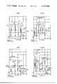
- FIG. 1generally depicts the use of the present invention with a gas chromatograph
- FIG. 2is a side view of the flame detector of FIG. 1;
- FIG. 3is a section taken along line 3--3 in FIG. 2;
- FIG. 4shows a cut away view of the detector of FIG. 2
- FIG. 5is a scan of test results obtained using the present invention to analyze a calibration gas
- FIG. 6is a scan of test results obtained using a prior art device to analyze calibration gas
- FIG. 7is a scan of test results from the present invention using a low sulfur sample.
- FIG. 8is a scan of test results from the present invention using a high sulfur sample.
- the present inventiongenerally relates to a method and apparatus for detection and measurement of sulfur and sulfur bearing compounds, and is more specifically directed at the detection and measurement of sulfur and sulfur bearing compounds in sour natural gas samples.
- an inert carrier gas 10such as nitrogen, entrains a sample of the gas to be analyzed in a sample injector 14.
- the carrier gasis piped to and from the injector 14 by lines 12 and 16 respectively.
- Line 16feeds into chromatograph column 18 wherein a physical separation of the sample's gaseous components, based on their respective partition coefficients, is carried out.
- the separation processis basically an adsorption process with the less mobile components of the gaseous sample (stationary phase) being physically bound to the column packing 20.
- the columnis inert to sulfur compounds which are contained in the mobile phase.
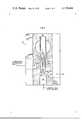
- flame detector 24comprises a detector block 36 with an inspection plate 38.
- Block 36is connected to a photomultiplier tube 40 by light tube 42.
- Light tube 42houses an optical filter (FIG. 4) and accessory devices such as secondary filters (not shown) and condensing lenses (not shown).
- the light tubemay be operated with a slightly pressurized gas to clear the tube of scattering or absorbing substances and dissipate undesirable levels of heat.
- Lead 32feeds the signal generated by the tube 40 to display 34 (FIG. 1).
- Hydrogen fuelis introduced into block 36 through port 44.
- a thermocouple(not shown), which allows continuous monitoring of detector block temperature, is inserted in port 46.
- Port 48is for insertion of an electrically operated heater cartridge capable of producing an operating temperature of 300° C. (572° F.).
- Port 50(shown in phantom) is for introduction of the combustion sustaining gas into the block.
- FIG. 3depicts block 36 in cutaway.
- Block 36is formed with cavities 54, 56, 58 and 60.
- Cavity 54extends from port 52 and is used for introducing the gas sample from column 18 into burner or flame tip 62.
- the burner or flame tipis preferably made of a high nickel alloy or other material relatively unreactive with sulfur.
- Cavity 56extends from port 44 and leads the hydrogen fuel to burner 62.
- a combustion sustaining gassuch as air or oxygen, enters block 36 through port 50 and flows through cavity 58 to an annular gas chamber 66 which surrounds the burner. This gas then feeds into cavity 60 to support combustion of the hydrogen and gas sample.
- a transparent chimney 68surrounds flame tip 64 and is held in position by support ring 70.
- the chimneyis constructed of transparent material which is preferably quartz or a laboratory grade glass such as Pyrex. The chimney extends a preselected distance above the uppermost portion of the flame tip and is critical to substantially improved performance of the unit.
- block 36is formed with an enlarged bore 72 transversing cavity 60.
- One end of the boreis used for access to the cavity and when not being so used is closed off by inspection plate 38 (FIG. 2).
- the bore's opposite endis attached to the photomultiplier tube 40 by the tightly sealed light tube 42.
- Light tube 42houses selective optical filter 74.
- the light tubeis critically positioned so that the line of sight of the sensing unit or its sensing area does not include any portion of the cool hydrogen flame.
- the optical filteris selective and allows only particular emissions to pass therethrough thus minimizing hydrocarbon interference.
- the analyzerhaving received the carrier gas and mobile phase from the chromatograph column operates in the following manner.
- the hydrogen fuel and gas sampleare mixed in the lower burner mixing area 65 and ignited by any conventional ignition arrangement.
- Combustion sustainig gasflows through the annular chamber 66 surrounding the burner and combusts with the hydrogen-sample gas mixture to produce a cool hydrogen flame.
- Such an arrangementimproves operational stability.
- the flame temperaturelies within the 300° C.-800° C. (572° F.-1472° F.) range rather than the 2300° C. (4172° F.) temperature of a common type of commercially available flame detection unit.
- the hydrogen to combustion gas (air) ratio and the hydrogen-carrier gas ratioare of the order of 3:1 and 5-8:1, respectively.
- the hydrogen to oxygen ratiois about 15:1.
- the cumulative effect of these selected flow ratiossignificantly contributes to producing the cool flame and clean flow effect and compares favorably with the prior art fuel to combustion gas ratio of 2:3.
- the clean flow effectis the most significant factor contributing to the detector's rapid response to the sulfur bearing constituents.
- Evidenceindicates that low energy S 2 molecules absorb 394 nm light producing an undesirable quenching effect on the properly excited molecules.
- the high flow rate carrier gasbesides contributing to the cooling effect of the flame, sweeps spent S 2 molecules (low level energy) from the detection device.
- Transparent chimney 68which surrounds the uppermost section of the burner and the entire flame, functions as a contact type heat exchanger to cool the excited S 2 molecules to a lower energy state where the 394 nm light emissions occur.
- the chimneyfurther serves to concentrate maximum emission of the light into a specific area above the hydrogen flame in full view of the sensing unit scan area. This particular enfiguration is credited with giving a 400-500% more specific response to sulfur than prior art units. Detector dead volume, which represents areas of stagnation of the decaying molecules, is significantly reduced by the presence and operation of the chimney device. This reduction is credited with the definite and sharp signal peak produced by the inventive detector.
- the chimneyisolates such species from being adsorbed on or chemically reacting with surrounding metal surfaces. Interreaction of any type with metal housing can seriously impair the analyzer's reliability. Dimensional characteristics of the chimney are important for it to efficiently and effectively function in the multipurpose manner above described.
- the chimneyshould have an inner diameter of 0.75 centimeters (0.34 inches) and extend 3 centimeters (1.35 inches) above the burner or flame tip. Variation from these dimensions leads to flame blow out and inefficient cooling of the over excited S 2 molecules.
- Filter 74may be of a type which allows a number of varied wave lengths to pass, or it may be a narrow band pass filter specific for the 394 nm wave length. The latter type filter effectively filters out most other signals.
- the selectively filtered emissionspass through the light tube to the photomultiplier where, based on the intensity of the emissions, an electrical signal is generated and amplified or merely generated and transmitted to a recording or a display panel.
- Comparative testing of the present invention with prior art devicesindicates superior performance over commercially available units.
- a calibration gas containing 0.5% of each of the following sulfur componentswas used to test and compare the present invention with a prior art device.
- FIGS. 7 and 8show the invention-detector's performance on gas samples containing 116 ppm and 113,000 ppm of H 2 S respectively.
- the gas samplesalso contained low concentrations of the other sulfur containing compounds listed and numbered as above. While attenuation adjustments were periodically needed with the higher concentration samples, reliably accurate results were obtained.
- the prior art devicecould not analyze the samples used for the data displayed in FIGS. 7 and 8.
- the present inventionhas also been found useful for analysis of sour natural gas samples and LPG fractions of petroleum.
- the devicecan detect a wide variety of sulfur bearing constituents in quantities from about 0.1 ppm up to and in excess of 5000 ppm. Specifically, in addition to those listed above, the device can be used for determination of sulfur dioxide (SO 2 ), carbon disulfide (CS 2 ) dimethylsulfide (C 2 H 6 S), ethylmethylsulfide (C 3 H 8 S), s-butyl, or i-butyl mercaptans (C 4 H 9 SH), and diethylsulfide (C 4 H 10 S).
- lightincludes not only visible light but also radiation having wavelengths longer and shorter than the visible spectrum.
Landscapes
- Health & Medical Sciences (AREA)
- Nuclear Medicine, Radiotherapy & Molecular Imaging (AREA)
- Physics & Mathematics (AREA)
- Life Sciences & Earth Sciences (AREA)
- Chemical & Material Sciences (AREA)
- Analytical Chemistry (AREA)
- Biochemistry (AREA)
- General Health & Medical Sciences (AREA)
- General Physics & Mathematics (AREA)
- Immunology (AREA)
- Pathology (AREA)
- Investigating, Analyzing Materials By Fluorescence Or Luminescence (AREA)
Abstract
Description
______________________________________ REFERENCE COMPONENT NUMERAL ______________________________________ Hydrogen Sulfide (H.sub.2 S) 110 Carbonyl Sulfide (COS) 112 Methyl Mercaptan (CH.sub.3 SH) 114 Ethyl Mercaptan (CH.sub.5 SH) 116 Isopropyl Mercaptan (C.sub.3 H.sub.7 SH) 118 n-Propyl Mercaptan (C.sub.3 H.sub.7 SH) 120 t-Butyl Mercaptan (C.sub.4 H.sub.9 SH) 122 n-Butyl Mercaptan (C.sub.4 H.sub.9 SH) 124 i-Butyl Mercaptan (C.sub.4 H.sub.9 SH) 126 ______________________________________
Claims (16)
Priority Applications (2)
| Application Number | Priority Date | Filing Date | Title |
|---|---|---|---|
| US05/812,899US4119404A (en) | 1977-07-05 | 1977-07-05 | Apparatus and method for sour gas analysis |
| CA300,890ACA1107983A (en) | 1977-07-05 | 1978-04-11 | Apparatus and method for sour gas analysis |
Applications Claiming Priority (1)
| Application Number | Priority Date | Filing Date | Title |
|---|---|---|---|
| US05/812,899US4119404A (en) | 1977-07-05 | 1977-07-05 | Apparatus and method for sour gas analysis |
Publications (1)
| Publication Number | Publication Date |
|---|---|
| US4119404Atrue US4119404A (en) | 1978-10-10 |
Family
ID=25210913
Family Applications (1)
| Application Number | Title | Priority Date | Filing Date |
|---|---|---|---|
| US05/812,899Expired - LifetimeUS4119404A (en) | 1977-07-05 | 1977-07-05 | Apparatus and method for sour gas analysis |
Country Status (2)
| Country | Link |
|---|---|
| US (1) | US4119404A (en) |
| CA (1) | CA1107983A (en) |
Cited By (11)
| Publication number | Priority date | Publication date | Assignee | Title |
|---|---|---|---|---|
| FR2438842A1 (en)* | 1978-10-13 | 1980-05-09 | Erba Strumentazione | METHOD AND APPARATUS FOR DETERMINING THE SULFUR CONTENT IN SAMPLE ANALYSIS |
| US4629704A (en)* | 1983-03-18 | 1986-12-16 | Boliden Aktiebolag | Method for assaying sulphur trioxide |
| US4668839A (en)* | 1985-06-14 | 1987-05-26 | Her Majesty The Queen In Right Of Canada, As Represented By The Minister Of Energy, Mines And Resources Canada | Process for the separation of sulphur compounds in bitumen, heavy oil and synthetic fuel distillates |
| US4818105A (en)* | 1987-09-21 | 1989-04-04 | Hewlett-Packard Company | Burner for flame photometric detector |
| US4999175A (en)* | 1985-02-01 | 1991-03-12 | European Atomic Energy Community (Euratom) | Process for selective adsorption of sulfur compounds from gaseous mixtures containing mercaptans |
| US6205841B1 (en)* | 1998-02-20 | 2001-03-27 | Shimadzu Corporation | Gas chromatograph |
| WO2015003051A1 (en)* | 2013-07-02 | 2015-01-08 | Garff Eric | Flame photometric detector |
| US20150285770A1 (en)* | 2010-02-26 | 2015-10-08 | Rosario Mannino | Jet assembly for use in detectors and other devices |
| CN111220747A (en)* | 2018-11-27 | 2020-06-02 | 中国科学院大连化学物理研究所 | Sulfur response signal enhancement assembly of flame photometric detector and application thereof |
| US20210364484A1 (en)* | 2020-05-22 | 2021-11-25 | Rosemount Inc. | Flame photometric detector |
| US20220276208A1 (en)* | 2019-01-14 | 2022-09-01 | Agilent Technologies, Inc. | Versatile tube-free jet for gas chromatography detector |
Citations (3)
| Publication number | Priority date | Publication date | Assignee | Title |
|---|---|---|---|---|
| US3423181A (en)* | 1966-06-06 | 1969-01-21 | Varian Associates | Thermionic detector for gas chromatography |
| US3486827A (en)* | 1966-09-09 | 1969-12-30 | Ceskoslovenska Akademie Ved | Burner for a flame photometer having a subatmospheric pressure combustion chamber |
| US3489498A (en)* | 1965-11-05 | 1970-01-13 | Melpar Inc | Flame photometric detector with improved specificity to sulfur and phosphorus |
- 1977
- 1977-07-05USUS05/812,899patent/US4119404A/ennot_activeExpired - Lifetime
- 1978
- 1978-04-11CACA300,890Apatent/CA1107983A/ennot_activeExpired
Patent Citations (3)
| Publication number | Priority date | Publication date | Assignee | Title |
|---|---|---|---|---|
| US3489498A (en)* | 1965-11-05 | 1970-01-13 | Melpar Inc | Flame photometric detector with improved specificity to sulfur and phosphorus |
| US3423181A (en)* | 1966-06-06 | 1969-01-21 | Varian Associates | Thermionic detector for gas chromatography |
| US3486827A (en)* | 1966-09-09 | 1969-12-30 | Ceskoslovenska Akademie Ved | Burner for a flame photometer having a subatmospheric pressure combustion chamber |
Non-Patent Citations (1)
| Title |
|---|
| Brody et al., J. Gas Chromat. 4, 42 (1966).* |
Cited By (16)
| Publication number | Priority date | Publication date | Assignee | Title |
|---|---|---|---|---|
| FR2438842A1 (en)* | 1978-10-13 | 1980-05-09 | Erba Strumentazione | METHOD AND APPARATUS FOR DETERMINING THE SULFUR CONTENT IN SAMPLE ANALYSIS |
| US4293308A (en)* | 1978-10-13 | 1981-10-06 | Carlo Erba Strumentazione S.P.A. | Method and apparatus for the analysis of sulphur contents in samples |
| US4629704A (en)* | 1983-03-18 | 1986-12-16 | Boliden Aktiebolag | Method for assaying sulphur trioxide |
| US4999175A (en)* | 1985-02-01 | 1991-03-12 | European Atomic Energy Community (Euratom) | Process for selective adsorption of sulfur compounds from gaseous mixtures containing mercaptans |
| US4668839A (en)* | 1985-06-14 | 1987-05-26 | Her Majesty The Queen In Right Of Canada, As Represented By The Minister Of Energy, Mines And Resources Canada | Process for the separation of sulphur compounds in bitumen, heavy oil and synthetic fuel distillates |
| US4818105A (en)* | 1987-09-21 | 1989-04-04 | Hewlett-Packard Company | Burner for flame photometric detector |
| US6205841B1 (en)* | 1998-02-20 | 2001-03-27 | Shimadzu Corporation | Gas chromatograph |
| US20150285770A1 (en)* | 2010-02-26 | 2015-10-08 | Rosario Mannino | Jet assembly for use in detectors and other devices |
| WO2015003051A1 (en)* | 2013-07-02 | 2015-01-08 | Garff Eric | Flame photometric detector |
| CN111220747A (en)* | 2018-11-27 | 2020-06-02 | 中国科学院大连化学物理研究所 | Sulfur response signal enhancement assembly of flame photometric detector and application thereof |
| CN111220747B (en)* | 2018-11-27 | 2022-03-15 | 中国科学院大连化学物理研究所 | Sulfur response signal enhancement assembly of flame photometric detector and application thereof |
| US20220276208A1 (en)* | 2019-01-14 | 2022-09-01 | Agilent Technologies, Inc. | Versatile tube-free jet for gas chromatography detector |
| US12117424B2 (en) | 2019-01-14 | 2024-10-15 | Agilent Technologies, Inc. | Versatile tube-free jet for gas chromatography detector having a conical inlet skirt |
| US12130266B2 (en)* | 2019-01-14 | 2024-10-29 | Agilent Technologies, Inc | Versatile tube-free jet for gas chromatography detector having a conical inlet skirt |
| US20210364484A1 (en)* | 2020-05-22 | 2021-11-25 | Rosemount Inc. | Flame photometric detector |
| US11506643B2 (en)* | 2020-05-22 | 2022-11-22 | Rosemount Inc. | Flame photometric detector |
Also Published As
| Publication number | Publication date |
|---|---|
| CA1107983A (en) | 1981-09-01 |
Similar Documents
| Publication | Publication Date | Title |
|---|---|---|
| US4119404A (en) | Apparatus and method for sour gas analysis | |
| Stevens et al. | Modern aspects of air pollution monitoring | |
| CN103175799A (en) | Method of calibrating and calibration apparatus for a moisture concentration measurement apparatus | |
| CN105911158A (en) | Gas chromatograph and detection method for determining total content of sulfides in natural gas | |
| US20140193922A1 (en) | Method for Combustion Analysis of Samples in a Combustion Analyzer | |
| US4554133A (en) | Gas measuring testing tube | |
| Khijwania et al. | A fiber optic Raman sensor for hydrocarbon detection | |
| Guha et al. | Gas composition of fluid inclusions using solid probe mass spectrometry and its application to study of mineralizing processes | |
| JP3858844B2 (en) | Gas monitoring apparatus and gas monitoring method for underground fixation of carbon dioxide gas | |
| Stedman et al. | Chemiluminescent measurement of parts-per-billion levels of nickel carbonyl in air | |
| Pack et al. | Use of an air/argon microwave plasma torch for the detection of tetraethyllead | |
| JP2005512052A (en) | Method and apparatus for detecting the presence of ammonium nitrate and sugars or hydrocarbons | |
| Navas et al. | Chemiluminescent methods in petroleum products analysis | |
| Kondrat’Eva et al. | Comparative study of gas-analyzing systems designed for continuous monitoring of TPP emissions | |
| Crider | Hydrogen-air flame chemiluminescence of some organic halides | |
| Baronick et al. | Evaluation of an uv analyzer for NOX vehicle emission measurement | |
| WO1995022049A1 (en) | Apparatus for simultaneous measurement of sulfur and non-sulfur containing compounds | |
| Luft | Infrared techniques for the measurement of carbon monoxide | |
| EP0502121A4 (en) | Process and apparatus for simultaneous measurement of sulfur and non-sulfur containing compounds | |
| US5708507A (en) | Temperature resolved molecular emission spectroscopy of materials | |
| US20050274899A1 (en) | Spectroscopic system and method for analysis in harsh, changing environments | |
| WO1994018541A1 (en) | Process and apparatus for positioning a probe in a flame for measurement of compounds combusted in the flame | |
| Smolkova-Keulemansova et al. | Analysis of substances in the gaseous phase | |
| Denkhaus et al. | Determination of gaseous nitrogen in gas mixtures using low pressure microwave induced plasma emission spectrometry | |
| Venkateshan | Gas Concentration |
Legal Events
| Date | Code | Title | Description |
|---|---|---|---|
| AS | Assignment | Owner name:WESTERN ATLAS INTERNATIONAL, INC., 10,001 RICHMOND Free format text:ASSIGNMENT OF ASSIGNORS INTEREST.;ASSIGNOR:WESTERN GEOPHYSICAL COMPANY OF AMERICA, A CORP OF DE;REEL/FRAME:004725/0239 Effective date:19870430 | |
| AS | Assignment | Owner name:CORE HOLDINGS B.V., (A DUTCH CORP.), NETHERLANDS Free format text:MORTGAGE;ASSIGNOR:CORE LAB HOLDINGS, INC.;REEL/FRAME:007186/0048 Effective date:19940930 Owner name:DOMESTIC AGENT FOR RECEIVING PARTY IS: MEESPIERSON Free format text:MORTGAGE;ASSIGNOR:CORE LAB HOLDINGS, INC.;REEL/FRAME:007186/0048 Effective date:19940930 | |
| AS | Assignment | Owner name:CORE HOLDINGS B.V., TEXAS Free format text:ASSIGNMENT OF ASSIGNORS INTEREST;ASSIGNOR:WESTERN ATLAS INTERNATIONAL, INC.;REEL/FRAME:007185/0581 Effective date:19940930 | |
| AS | Assignment | Owner name:MEESPIERSON N.V., NEW YORK Free format text:CORRECTIVE ASSIGNEE TO CORRECT THE ASSIGNOR AND ASSIGNEE PREVIOUSLY RECORDED ON REEL 7186, FRAME 049.;ASSIGNOR:CORE HOLDINGS B.V. (A DUTCH CORP.);REEL/FRAME:007286/0091 Effective date:19940930 | |
| AS | Assignment | Owner name:CORE LABORATORIES, INC., TEXAS Free format text:GENERAL RELEASE;ASSIGNOR:MEESPIERSON, N.V. NEW YORK AGENCY;REEL/FRAME:008568/0435 Effective date:19951002 |