US4117640A - Thermal barrier system for panel installations - Google Patents
Thermal barrier system for panel installationsDownload PDFInfo
- Publication number
- US4117640A US4117640AUS05/776,992US77699277AUS4117640AUS 4117640 AUS4117640 AUS 4117640AUS 77699277 AUS77699277 AUS 77699277AUS 4117640 AUS4117640 AUS 4117640A
- Authority
- US
- United States
- Prior art keywords
- legs
- coupler
- slot
- pair
- gutter
- Prior art date
- Legal status (The legal status is an assumption and is not a legal conclusion. Google has not performed a legal analysis and makes no representation as to the accuracy of the status listed.)
- Expired - Lifetime
Links
- 238000009434installationMethods0.000titleclaimsabstractdescription19
- 230000004888barrier functionEffects0.000titleclaimsabstract3
- 238000009413insulationMethods0.000claimsdescription3
- 230000037431insertionEffects0.000claims2
- 238000003780insertionMethods0.000claims2
- 239000011810insulating materialSubstances0.000claims2
- 239000000463materialSubstances0.000description3
- 239000011521glassSubstances0.000description2
- 229910052751metalInorganic materials0.000description2
- 239000002184metalSubstances0.000description2
- 230000002093peripheral effectEffects0.000description2
- 229910052782aluminiumInorganic materials0.000description1
- XAGFODPZIPBFFR-UHFFFAOYSA-NaluminiumChemical compound[Al]XAGFODPZIPBFFR-UHFFFAOYSA-N0.000description1
- 239000004020conductorSubstances0.000description1
- 229920003023plasticPolymers0.000description1
- 239000004033plasticSubstances0.000description1
- 229920001084poly(chloroprene)Polymers0.000description1
- 239000004800polyvinyl chlorideSubstances0.000description1
- 229920000915polyvinyl chloridePolymers0.000description1
- 239000012858resilient materialSubstances0.000description1
Images


Classifications
- E—FIXED CONSTRUCTIONS
- E06—DOORS, WINDOWS, SHUTTERS, OR ROLLER BLINDS IN GENERAL; LADDERS
- E06B—FIXED OR MOVABLE CLOSURES FOR OPENINGS IN BUILDINGS, VEHICLES, FENCES OR LIKE ENCLOSURES IN GENERAL, e.g. DOORS, WINDOWS, BLINDS, GATES
- E06B3/00—Window sashes, door leaves, or like elements for closing wall or like openings; Layout of fixed or moving closures, e.g. windows in wall or like openings; Features of rigidly-mounted outer frames relating to the mounting of wing frames
- E06B3/04—Wing frames not characterised by the manner of movement
- E06B3/263—Frames with special provision for insulation
- E06B3/26338—Frames with special provision for insulation comprising short insulating elements disposed at intervals
- E—FIXED CONSTRUCTIONS
- E06—DOORS, WINDOWS, SHUTTERS, OR ROLLER BLINDS IN GENERAL; LADDERS
- E06B—FIXED OR MOVABLE CLOSURES FOR OPENINGS IN BUILDINGS, VEHICLES, FENCES OR LIKE ENCLOSURES IN GENERAL, e.g. DOORS, WINDOWS, BLINDS, GATES
- E06B3/00—Window sashes, door leaves, or like elements for closing wall or like openings; Layout of fixed or moving closures, e.g. windows in wall or like openings; Features of rigidly-mounted outer frames relating to the mounting of wing frames
- E06B3/54—Fixing of glass panes or like plates
- E06B3/5409—Means for locally spacing the pane from the surrounding frame
- E—FIXED CONSTRUCTIONS
- E06—DOORS, WINDOWS, SHUTTERS, OR ROLLER BLINDS IN GENERAL; LADDERS
- E06B—FIXED OR MOVABLE CLOSURES FOR OPENINGS IN BUILDINGS, VEHICLES, FENCES OR LIKE ENCLOSURES IN GENERAL, e.g. DOORS, WINDOWS, BLINDS, GATES
- E06B3/00—Window sashes, door leaves, or like elements for closing wall or like openings; Layout of fixed or moving closures, e.g. windows in wall or like openings; Features of rigidly-mounted outer frames relating to the mounting of wing frames
- E06B3/04—Wing frames not characterised by the manner of movement
- E06B3/263—Frames with special provision for insulation
- E06B2003/26392—Glazing bars
- E—FIXED CONSTRUCTIONS
- E06—DOORS, WINDOWS, SHUTTERS, OR ROLLER BLINDS IN GENERAL; LADDERS
- E06B—FIXED OR MOVABLE CLOSURES FOR OPENINGS IN BUILDINGS, VEHICLES, FENCES OR LIKE ENCLOSURES IN GENERAL, e.g. DOORS, WINDOWS, BLINDS, GATES
- E06B3/00—Window sashes, door leaves, or like elements for closing wall or like openings; Layout of fixed or moving closures, e.g. windows in wall or like openings; Features of rigidly-mounted outer frames relating to the mounting of wing frames
- E06B3/04—Wing frames not characterised by the manner of movement
- E06B3/263—Frames with special provision for insulation
- E06B2003/26398—Frames with special provision for insulation with two metal sections clamping a pane
- Y—GENERAL TAGGING OF NEW TECHNOLOGICAL DEVELOPMENTS; GENERAL TAGGING OF CROSS-SECTIONAL TECHNOLOGIES SPANNING OVER SEVERAL SECTIONS OF THE IPC; TECHNICAL SUBJECTS COVERED BY FORMER USPC CROSS-REFERENCE ART COLLECTIONS [XRACs] AND DIGESTS
- Y10—TECHNICAL SUBJECTS COVERED BY FORMER USPC
- Y10S—TECHNICAL SUBJECTS COVERED BY FORMER USPC CROSS-REFERENCE ART COLLECTIONS [XRACs] AND DIGESTS
- Y10S49/00—Movable or removable closures
- Y10S49/01—Thermal breaks for frames
Definitions
- the inventionpertains generally to apparatus for holding panel members in conjunction with structures.
- FIG. 1is a perspective view of the exterior of a panel installation
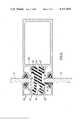
- FIG. 2is a sectional view of the panel installation of FIG. 1 along the line 2--2;
- FIG. 3is a sectional view of the panel installation of FIG. 1 taken along the line 3--3;
- FIG. 4is a sectional view of the panel installation of FIG. 1 taken along the line 4--4;
- FIG. 5is a fragmentary view of a portion of the panel installation of FIG. 1 in a partially assembled condition.
- a panel installation 10is attached to a structure 12.
- Panel installation 10comprises a plurality of frames 14.
- Each frame 14contains an exterior panel 16.
- Panel 16may comprise glass, as in the case of a window, or other type of panel deemed desirable for structural or ornamental purposes.
- Frames 14are fabricated of aluminum or other metallic or thermally conductive material.
- Frame 14comprises an upper portion 18 joined to a pair of jambs 20, which are in turn joined to a sill 22.
- a pair of mullions 24are joined to jambs 20 intermediately of upper portion 18 and sill 22.
- the frame 14comprises a gutter member 28 attachable by conventional means (not shown) to structure 12.
- Gutter member 28comprises a rear wall 30 which is disposed adjacent structure 12.
- Gutter member 28also includes an upper wall 32 and a lower wall 34, both joined to rear wall 30.
- Upper wall 32includes a downwardly directed flange 36
- lower wall 34includes an upwardly directed flange 38.
- the walls 30, 32, 34 and flanges 36, 38form a pair of slots 40.
- a face member 42comprises the exterior surface of the frame 14. Face member 42 comprises a forward wall 44 and an upper wall and lower wall 46, 48, respectively. Upper wall 46 includes a downwardly directed flange 52 and wall 48 includes an upwardly directed flange 54. Walls 44, 46, 48 and flanges 52, 54 define a pair of slots 56.
- Coupler member 60is connected between gutter member 28 and face member 42. Coupler member 60 comprises a body portion 61 which defines an intermediate twist connector aperture 62. Coupler 60 includes first connector means comprising a first pair of legs 63; at the opposite end of coupler 60 is a second connector means comprising a second pair of legs 64. An arm 65, attached to coupler 60, extends inwardly to brace panel 16. A pair of shoulders 66 is attached to member 60 outwardly of legs 63.
- First legs 63include upper and lower ends 67, 67', respectively.
- Upper end 67includes an upper surface having a rounded peripheral portion 68; lower end 67' has a similar rounded portion 68' disposed diagonally opposite to rounded portion 68. These rounded portions cooperate to permit ready assembly of the installation as described in detail below.
- Second legs 64include upper and lower ends 69, 69', respectively. Ends 69, 69' taper outwardly.
- Upper and lower lips 70, 70'are disposed behind ends 69, 69', respectively.
- Upper lip 70has an upper edge having a peripheral rounded portion 71.
- Lower lip 70'has a similar rounded portion (not shown) disposed diagonally opposite to rounded portion 71.
- the tapered ends 69, 69'facilitate assembly of the installation, and the rounded portions of lips 70, 70' permit convenient disengagement of legs 64 from face member 42 as described in detail below.
- Coupler member 60is fabricated of resilient insulated material, such as plastic.
- First legs 63are of greater thickness than legs 64 and are spaced at a smaller distance from one another than are legs 64; legs 63 are less readily compressible together than are legs 64.
- first legs 63 of the coupler member 60are disposed in locking engagement with first slots 40, the legs being configured to fit snugly into said slots and being held in position by the resiliency of the material.
- Shoulders 66are engaged against flanges 36, 38 and augment locking engagement of the coupler 60 with gutter member 28.
- Second legs 64are configured to be disposed within second slots 56 and are held therein also by the resiliency of the material.
- a pair of arms 72, 73extend from the upper end and lower end, respectively, of gutter member 28. Arms 72, 73 include at their ends holders 74, 76, respectively. Held within holders 74, 76 are a pair of gaskets 78. Gaskets 78 are of resilient material, such as neoprene or polyvinylchloride, and are in contact with panel 16.
- a support member 79 attached to gutter member 28extends outwardly therefrom and under panel 16 to provide support thereto.
- Support member 79includes a female element 80 comprising a pair of legs 81 which are mounted upon walls 32, 34 and between arms 72, 73.
- the female element 80includes a bifurcated portion 82 defining a slot 83 and extending beneath panel 16.
- a male element 84is mounted in slot 83 and includes a support portion 85 disposed in contact with the surface of the bifurcated portion 82 and the bottom of panel 16 to provide support therefor.
- a pair of gaskets 86contacts panel 16 and is disposed within a pair of holders 87, 88 disposed at upper and lower ends, respectively, of face member 42. Gaskets 86 are similar to gaskets 78 and act in conjunction therewith to brace panel 16.
- Coupler member 60is positioned so that legs 63 are disposed sideways within slots 40. Legs 63 are then positioned into slots 40 by a substantially 90° rotation and remain in locked engagement therewith. Rounded portions 69, 69' move within the walls 32, 34 of slots 40 in conjunction with such positioning. Second legs 64 are placed into slots 56 by snapping the face member in place, flanges 52, 54 sliding along the tapered ends of legs 64 and compressing legs 64 together thereby. To disconnect the assembly, coupler 60 is rotated in a reverse sense with a wire or convenient flat tool engaged in the twist connector aperture 62.
Landscapes
- Engineering & Computer Science (AREA)
- Civil Engineering (AREA)
- Structural Engineering (AREA)
- Building Environments (AREA)
Abstract
Description
1. Field of the Invention
The invention pertains generally to apparatus for holding panel members in conjunction with structures.
2. Description of the Prior Art
The use of metallic frames for panel installations on buildings has become widespread over the years. The advantages of metal frames for the panels are numerous. Among them are the durability and structural strength of such frames as well as their amenability to ornamental uses. There has been a substantial and continuing problem of insulation with respect to such panel installations due to the thermal conductivity of the metal, however.
Numerous prior art devices address themselves to the insulation problem of such panel installations. One such device is that described and claimed in U.S. Pat. No. 3,527,011 (Bloom, et al.) for insulating panels. Generally, the prior art devices utilize a combination of an insulative intermediate member joining the face and the other members of a panel installation. The individual components, however, do not allow for easy disengagement as is required for reglazing glass panels after breakage and for other panels for a variety of reasons.
Therefore, there has been a felt but unfulfilled need for a panel installation having thermal insulative properties having components which are relatively readily installable and removable.
FIG. 1 is a perspective view of the exterior of a panel installation;
FIG. 2 is a sectional view of the panel installation of FIG. 1 along the line 2--2;
FIG. 3 is a sectional view of the panel installation of FIG. 1 taken along theline 3--3;
FIG. 4 is a sectional view of the panel installation of FIG. 1 taken along the line 4--4; and
FIG. 5 is a fragmentary view of a portion of the panel installation of FIG. 1 in a partially assembled condition.
As depicted in FIGS. 1-5, a panel installation 10 is attached to astructure 12. Panel installation 10 comprises a plurality offrames 14. Eachframe 14 contains anexterior panel 16.Panel 16 may comprise glass, as in the case of a window, or other type of panel deemed desirable for structural or ornamental purposes.Frames 14 are fabricated of aluminum or other metallic or thermally conductive material.
Hereinbelow, like parts will be referred to by like numerals and will be described with reference to one such like part.Frame 14 comprises an upper portion 18 joined to a pair ofjambs 20, which are in turn joined to asill 22. A pair ofmullions 24 are joined to jambs 20 intermediately of upper portion 18 andsill 22.
Theframe 14 comprises agutter member 28 attachable by conventional means (not shown) to structure 12. Guttermember 28 comprises arear wall 30 which is disposedadjacent structure 12. Guttermember 28 also includes anupper wall 32 and alower wall 34, both joined torear wall 30.Upper wall 32 includes a downwardly directedflange 36, andlower wall 34 includes an upwardly directedflange 38. Thewalls flanges slots 40.
Aface member 42 comprises the exterior surface of theframe 14.Face member 42 comprises aforward wall 44 and an upper wall andlower wall Upper wall 46 includes a downwardly directed flange 52 andwall 48 includes an upwardly directedflange 54. Walls 44, 46, 48 andflanges 52, 54 define a pair ofslots 56.
A coupler member 60 is connected betweengutter member 28 andface member 42. Coupler member 60 comprises a body portion 61 which defines an intermediatetwist connector aperture 62. Coupler 60 includes first connector means comprising a first pair oflegs 63; at the opposite end of coupler 60 is a second connector means comprising a second pair oflegs 64. Anarm 65, attached to coupler 60, extends inwardly tobrace panel 16. A pair ofshoulders 66 is attached to member 60 outwardly oflegs 63.
Coupler member 60 is fabricated of resilient insulated material, such as plastic.First legs 63 are of greater thickness thanlegs 64 and are spaced at a smaller distance from one another than arelegs 64;legs 63 are less readily compressible together than arelegs 64.
In the assembled condition,first legs 63 of the coupler member 60 are disposed in locking engagement withfirst slots 40, the legs being configured to fit snugly into said slots and being held in position by the resiliency of the material.Shoulders 66 are engaged againstflanges gutter member 28.Second legs 64 are configured to be disposed withinsecond slots 56 and are held therein also by the resiliency of the material.
A pair ofarms gutter member 28.Arms ends holders holders gaskets 78.Gaskets 78 are of resilient material, such as neoprene or polyvinylchloride, and are in contact withpanel 16.
As depicted in FIG. 4, asupport member 79 attached togutter member 28 extends outwardly therefrom and underpanel 16 to provide support thereto.Support member 79 includes afemale element 80 comprising a pair oflegs 81 which are mounted uponwalls arms female element 80 includes abifurcated portion 82 defining aslot 83 and extending beneathpanel 16. Amale element 84 is mounted inslot 83 and includes asupport portion 85 disposed in contact with the surface of thebifurcated portion 82 and the bottom ofpanel 16 to provide support therefor.
A pair ofgaskets 86contacts panel 16 and is disposed within a pair ofholders face member 42.Gaskets 86 are similar togaskets 78 and act in conjunction therewith to bracepanel 16.
Connection of thegutter member 28 andface member 42 with coupler member 60 to form a frame is readily accomplished. Coupler member 60 is positioned so thatlegs 63 are disposed sideways withinslots 40.Legs 63 are then positioned intoslots 40 by a substantially 90° rotation and remain in locked engagement therewith.Rounded portions 69, 69' move within thewalls slots 40 in conjunction with such positioning.Second legs 64 are placed intoslots 56 by snapping the face member in place,flanges 52, 54 sliding along the tapered ends oflegs 64 and compressinglegs 64 together thereby. To disconnect the assembly, coupler 60 is rotated in a reverse sense with a wire or convenient flat tool engaged in thetwist connector aperture 62. Rounded ends of lips 70, 70' slide alongflanges 52, 54 to facilitate such disconnection. This disengages the coupler 60 from both thegutter member 28 and theface member 42 thus disassembling theframe 14. By thus using a flat tool to twist the coupler 60, the tool slips by thegaskets panel 16 remaining in place.
Thus, a thermally insulated panel installation having readily assembleable and disassembleable components is provided by the invention. Though a particular embodiment of the invention has been described and depicted above, the invention is defined solely by the appended claims.
Claims (14)
1. A thermal barrier system for panel installations comprising:
at least one gutter member including means for attachment to a structure, said gutter member defining first forwardly facing slot means and including first flange means adjacent said first slot means;
at least one face member, said face member defining second rearwardly facing slot means and including second flange means adjacent said second slot means;
at least one coupler member comprising a unitary body of heat insulating material, the latter member having first connector means rotatable in one direction in said first slot means of said gutter member to form a locking engagement with said first slot means and said first flange means, said coupler member further including resilient second connector means snap fittable into said second slot means of said face member to form a locking engagement with said second slot means and said second flange means, said first connector means and said second connector means being disengageable from said gutter member and said face member, respectively, by a reverse rotation of said coupler member; and means adjacent said first and second slot means, respectively, for engaging and holding an edge of a panel member.
2. The invention as set forth in claim 1 wherein said coupler member includes shoulder means for contacting said first slot means and said first flange means to cooperate in forming said locking engagement of said first connector means with said gutter member.
3. The invention as set forth in claim 1 wherein said at least one face member comprises a plurality thereof, said at least one gutter member comprises a plurality thereof, and said at least one insulative coupler member comprises a plurality thereof, such that when said insulative coupler member is attached between said gutter member and said face member, they form a plurality of connected pairs, said plurality of connected pairs forming a frame for a panel.
4. The invention as set forth in claim 1 wherein said at least one coupler member defines an aperture for insertion of a twisting tool thereinto.
5. A thermal insulation system for panel installations comprising:
at least one gutter member, said gutter member including a first wall member and at least a pair of first flanges, said first wall member and said first flanges defining at least a first forwardly facing slot;
at least one face member, said face member including a second wall member and at least a pair of second flanges attached thereto, said second wall member and said at least one pair of second flanges defining at least a second rearwardly facing slot;
at least one coupler member, said coupler member comprising a unitary body of heat insulating material defining first connector means rotatable in said first slot of said gutter member into locking engagement with said first slot and with said pair of first flanges, said coupler member further including second connector means snap fittable into said second slot in said face member in locking engagement with said pair of second slots and with said pair of second flanges; and
means adjacent said first and second slot means, respectively, for engaging and holding an edge of a panel member.
6. The invention as set forth in claim 5 wherein said coupler member comprises a body portion, wherein said first connector means comprises a pair of first legs attached to said body portion, and wherein said second connector means comprises a pair of second legs attached to said body portion, said first legs being configured to fit within said first slot means and being rotatable through a substantially 90° angle of rotation to form said locking engagement with said first slot means and said first flanges, said second legs being configured to fit within said second slot means and being resilient to be snappable into said locking engagement.
7. The invention as set forth in claim 6 wherein said first legs and said second legs are disengageable from said locking engagement by a reverse rotation of said coupler member.
8. The invention as set forth in claim 6 further including a pair of shoulder members on said body portion, said shoulder members being resilient and positioned to contact said first flanges in locking engagement therewith when said first legs are in said locking engagement in said first slots.
9. The invention as set forth in claim 6 wherein said coupler member includes a pair of lip means, each of said lip means being disposed adjacent one of said second legs, for contacting said second flanges when said second legs are in locking engagement with said face member to permit motion of said second legs when said coupler member is rotated.
10. The invention as set forth in claim 7 wherein said first legs include portions configured to permit motion of said first legs within said first slots upon rotation of said coupler member.
11. The invention as set forth in claim 1 wherein said gutter member includes gasket means for engaging a panel between said face member and said gutter member.
12. The invention as set forth in claim 1 wherein said at least one face member includes gasket means for engaging a panel between said face member and said gutter member.
13. The invention as set forth in claim 6 wherein said coupler member defines an aperture within said body portion thereof for insertion of a twisting tool thereinto.
14. The invention as set forth in claim 6 further including a support member for contacting a lower end of a panel, said support member being mountable upon said first flanges.
Priority Applications (1)
| Application Number | Priority Date | Filing Date | Title |
|---|---|---|---|
| US05/776,992US4117640A (en) | 1977-03-14 | 1977-03-14 | Thermal barrier system for panel installations |
Applications Claiming Priority (1)
| Application Number | Priority Date | Filing Date | Title |
|---|---|---|---|
| US05/776,992US4117640A (en) | 1977-03-14 | 1977-03-14 | Thermal barrier system for panel installations |
Publications (1)
| Publication Number | Publication Date |
|---|---|
| US4117640Atrue US4117640A (en) | 1978-10-03 |
Family
ID=25108955
Family Applications (1)
| Application Number | Title | Priority Date | Filing Date |
|---|---|---|---|
| US05/776,992Expired - LifetimeUS4117640A (en) | 1977-03-14 | 1977-03-14 | Thermal barrier system for panel installations |
Country Status (1)
| Country | Link |
|---|---|
| US (1) | US4117640A (en) |
Cited By (47)
| Publication number | Priority date | Publication date | Assignee | Title |
|---|---|---|---|---|
| EP0018516A3 (en)* | 1979-04-20 | 1981-02-04 | Wilhelm Hasselbacher | Compound section consisting of two metal parts held together by an insulating profiled member |
| EP0076703A1 (en)* | 1981-10-07 | 1983-04-13 | Francois Xavier Laroche | Structural units and modules for framed buildings |
| US4388784A (en)* | 1980-08-04 | 1983-06-21 | Wasco Products, Inc. | Thermal break skylight |
| US4428171A (en) | 1982-03-12 | 1984-01-31 | Atlantic Richfield Company | Thermal storefront system |
| US4429502A (en) | 1981-03-18 | 1984-02-07 | Kinnebrew Iv Joseph E | Transit shelter |
| US4462196A (en)* | 1981-06-18 | 1984-07-31 | P.C. Freiberg Pty. Ltd. | Means for interconnecting panels |
| DE3305623A1 (en)* | 1983-02-18 | 1984-08-30 | Siegfried 6074 Rödermark Kraus | Heat-insulating shell made of light metal sections |
| US4514943A (en)* | 1980-08-04 | 1985-05-07 | Wasco Products, Inc. | Thermal break skylight |
| US4707959A (en)* | 1985-02-28 | 1987-11-24 | Stoakes Richard Lewis | Structural assemblies such as curtain walling |
| US4750310A (en)* | 1986-11-26 | 1988-06-14 | Kawneer Company, Inc. | Storefront framing system |
| US4896613A (en)* | 1987-08-25 | 1990-01-30 | Elke Salzer | Composite bombardment inhibiting section for frame members |
| AT390473B (en)* | 1988-04-19 | 1990-05-10 | Thurnher Julius | PROFILE FRAME FOR SLIDING DOORS OR WINDOWS |
| US5291705A (en)* | 1992-05-20 | 1994-03-08 | Super Sky Products, Inc. | Encased skylight framework |
| US5363628A (en)* | 1992-02-05 | 1994-11-15 | Alumax Extrusions, Inc. | Thermal barrier apparatus and process for fabricating same |
| US5469683A (en)* | 1994-02-09 | 1995-11-28 | Kawneer Company, Inc. | Thermally insulating composite frame member with snap-in thermal isolator |
| US5481839A (en)* | 1992-09-09 | 1996-01-09 | Kawneer Company, Inc. | Glazed panel wall construction and method for assembly thereof |
| US5595033A (en)* | 1995-05-26 | 1997-01-21 | John R. Frey | Plastic block |
| US5632125A (en)* | 1994-04-21 | 1997-05-27 | Ykk Architectural Products Inc. | Curtain wall |
| US20030205009A1 (en)* | 2000-05-30 | 2003-11-06 | Herbst Walter M | Architectural panel fabrication system |
| US6735912B2 (en)* | 2001-10-30 | 2004-05-18 | Steve Riggio | Method and apparatus of weather sealing adjacently jointed building panels |
| US20040159059A1 (en)* | 2002-12-06 | 2004-08-19 | Blundo Frank N. | Apparatus and method for framing and isolating window and door openings of a building |
| US20050284069A1 (en)* | 2004-06-14 | 2005-12-29 | Goodnough Robert A | Prefabricated wall structure system |
| US20070251183A1 (en)* | 2006-04-13 | 2007-11-01 | Chinniah Thiagarajan | Apparatus for connecting panels |
| US20100287858A1 (en)* | 2009-05-13 | 2010-11-18 | Sabic Innovative Plastics Ip B.V. | Connector assemblies for connecting panels |
| US20110107712A1 (en)* | 2008-12-25 | 2011-05-12 | Taikisha Ltd. | Factory Building Assembly Structure and Method for Assembling Factory Building Using the Same |
| US20110226217A1 (en)* | 2010-03-16 | 2011-09-22 | Briggs & Stratton Corporation | Engine speed control system |
| US20120214397A1 (en)* | 2011-02-17 | 2012-08-23 | Peter Strycharske | Method and apparatus for convective sill insulation |
| US8485313B2 (en) | 2010-06-18 | 2013-07-16 | Briggs & Stratton Corporation | Muffler and engine system |
| US20140053488A1 (en)* | 2012-08-22 | 2014-02-27 | Alcoa Inc. | Inserts for hollow structural members |
| WO2014055617A1 (en)* | 2012-10-02 | 2014-04-10 | Technical Glass Products | Barrier to heat transparent wall system |
| US8910616B2 (en) | 2011-04-21 | 2014-12-16 | Briggs & Stratton Corporation | Carburetor system for outdoor power equipment |
| US8915231B2 (en) | 2010-03-16 | 2014-12-23 | Briggs & Stratton Corporation | Engine speed control system |
| US20150047280A1 (en)* | 2013-08-19 | 2015-02-19 | Rogers Athletic Company, Inc. | Demountable barrier system |
| US9074372B2 (en) | 2012-04-26 | 2015-07-07 | Sabic Global Technologies B.V. | Connector assemblies for connecting panels |
| US20150284951A1 (en)* | 2014-02-24 | 2015-10-08 | Todd Frederick | Curtain wall mullions, transoms and systems |
| US9234345B1 (en) | 2015-04-21 | 2016-01-12 | William F. O'Keeffe | Snap-together fire resistant fenestration frame apparatus |
| US20160088773A1 (en)* | 2013-01-11 | 2016-03-24 | Chatsworth Products, Inc. | Modular thermal isolation barrier for data processing equipment structure |
| US9312411B2 (en) | 2012-04-26 | 2016-04-12 | Sabic Global Technologies B.V. | Connector assemblies for connecting panels, panels with connector assemblies |
| US9316175B2 (en) | 2010-03-16 | 2016-04-19 | Briggs & Stratton Corporation | Variable venturi and zero droop vacuum assist |
| US20160265221A1 (en)* | 2011-12-14 | 2016-09-15 | Pella Corporation | Thermal break for curtain wall |
| US9949406B2 (en) | 2013-12-17 | 2018-04-17 | Chatsworth Products, Inc. | Electronic equipment enclosure |
| US10309150B2 (en)* | 2017-09-14 | 2019-06-04 | Arconic Inc. | Structural glazing weather seal with captured glazing option |
| WO2019168819A1 (en) | 2018-02-27 | 2019-09-06 | Arconic Inc. | Monolithic thermal break structural member |
| US10450743B2 (en)* | 2014-02-24 | 2019-10-22 | Fremarq Innovations, Inc. | Window and curtain wall mullions, transoms and systems |
| WO2020165065A1 (en)* | 2019-02-12 | 2020-08-20 | Assa Abloy Entrance Systems Ab | Door profile |
| GB2604579A (en)* | 2021-01-28 | 2022-09-14 | Garner Aluminium Extrusions Ltd | A window frame assembly |
| US12119781B2 (en)* | 2022-05-26 | 2024-10-15 | Eli Delozier | Gap cover |
Citations (10)
| Publication number | Priority date | Publication date | Assignee | Title |
|---|---|---|---|---|
| US2898643A (en)* | 1957-04-26 | 1959-08-11 | Gen Motors Corp | Window frame |
| US3004636A (en)* | 1959-03-18 | 1961-10-17 | Flush Metal Partition Corp | Ceiling support member with adjustable hanger bolts |
| US3031049A (en)* | 1958-03-31 | 1962-04-24 | A V R Achat Ventes Representat | Fastening device for metal constructions |
| US3191727A (en)* | 1962-11-06 | 1965-06-29 | Aluminum Co Of America | Framing structures |
| FR2005438A1 (en)* | 1968-04-03 | 1969-12-12 | Steiner Karl | |
| GB1179607A (en)* | 1966-11-04 | 1970-01-28 | Metaux Legers & Metaux Non Fer | A Glazing Bar and Glazing Strip Assembly |
| US3527011A (en)* | 1967-12-29 | 1970-09-08 | Cronstroms Mfg Inc | Insulated panel frame |
| US3553918A (en)* | 1967-12-07 | 1971-01-12 | Ppg Industries Inc | Insulated curtain wall construction |
| DE2130496A1 (en)* | 1971-06-19 | 1972-12-21 | Werner Frach | Window or the like with a metallic frame and / or wing frame |
| US4015388A (en)* | 1976-01-14 | 1977-04-05 | Ppg Industries, Inc. | Retaining clip for a division bar |
- 1977
- 1977-03-14USUS05/776,992patent/US4117640A/ennot_activeExpired - Lifetime
Patent Citations (10)
| Publication number | Priority date | Publication date | Assignee | Title |
|---|---|---|---|---|
| US2898643A (en)* | 1957-04-26 | 1959-08-11 | Gen Motors Corp | Window frame |
| US3031049A (en)* | 1958-03-31 | 1962-04-24 | A V R Achat Ventes Representat | Fastening device for metal constructions |
| US3004636A (en)* | 1959-03-18 | 1961-10-17 | Flush Metal Partition Corp | Ceiling support member with adjustable hanger bolts |
| US3191727A (en)* | 1962-11-06 | 1965-06-29 | Aluminum Co Of America | Framing structures |
| GB1179607A (en)* | 1966-11-04 | 1970-01-28 | Metaux Legers & Metaux Non Fer | A Glazing Bar and Glazing Strip Assembly |
| US3553918A (en)* | 1967-12-07 | 1971-01-12 | Ppg Industries Inc | Insulated curtain wall construction |
| US3527011A (en)* | 1967-12-29 | 1970-09-08 | Cronstroms Mfg Inc | Insulated panel frame |
| FR2005438A1 (en)* | 1968-04-03 | 1969-12-12 | Steiner Karl | |
| DE2130496A1 (en)* | 1971-06-19 | 1972-12-21 | Werner Frach | Window or the like with a metallic frame and / or wing frame |
| US4015388A (en)* | 1976-01-14 | 1977-04-05 | Ppg Industries, Inc. | Retaining clip for a division bar |
Cited By (75)
| Publication number | Priority date | Publication date | Assignee | Title |
|---|---|---|---|---|
| EP0018516A3 (en)* | 1979-04-20 | 1981-02-04 | Wilhelm Hasselbacher | Compound section consisting of two metal parts held together by an insulating profiled member |
| US4388784A (en)* | 1980-08-04 | 1983-06-21 | Wasco Products, Inc. | Thermal break skylight |
| US4514943A (en)* | 1980-08-04 | 1985-05-07 | Wasco Products, Inc. | Thermal break skylight |
| US4429502A (en) | 1981-03-18 | 1984-02-07 | Kinnebrew Iv Joseph E | Transit shelter |
| US4462196A (en)* | 1981-06-18 | 1984-07-31 | P.C. Freiberg Pty. Ltd. | Means for interconnecting panels |
| EP0076703A1 (en)* | 1981-10-07 | 1983-04-13 | Francois Xavier Laroche | Structural units and modules for framed buildings |
| US4428171A (en) | 1982-03-12 | 1984-01-31 | Atlantic Richfield Company | Thermal storefront system |
| DE3305623A1 (en)* | 1983-02-18 | 1984-08-30 | Siegfried 6074 Rödermark Kraus | Heat-insulating shell made of light metal sections |
| US4707959A (en)* | 1985-02-28 | 1987-11-24 | Stoakes Richard Lewis | Structural assemblies such as curtain walling |
| US4750310A (en)* | 1986-11-26 | 1988-06-14 | Kawneer Company, Inc. | Storefront framing system |
| US4896613A (en)* | 1987-08-25 | 1990-01-30 | Elke Salzer | Composite bombardment inhibiting section for frame members |
| AT390473B (en)* | 1988-04-19 | 1990-05-10 | Thurnher Julius | PROFILE FRAME FOR SLIDING DOORS OR WINDOWS |
| US5363628A (en)* | 1992-02-05 | 1994-11-15 | Alumax Extrusions, Inc. | Thermal barrier apparatus and process for fabricating same |
| US5291705A (en)* | 1992-05-20 | 1994-03-08 | Super Sky Products, Inc. | Encased skylight framework |
| US5481839A (en)* | 1992-09-09 | 1996-01-09 | Kawneer Company, Inc. | Glazed panel wall construction and method for assembly thereof |
| US5469683A (en)* | 1994-02-09 | 1995-11-28 | Kawneer Company, Inc. | Thermally insulating composite frame member with snap-in thermal isolator |
| US5632125A (en)* | 1994-04-21 | 1997-05-27 | Ykk Architectural Products Inc. | Curtain wall |
| US5595033A (en)* | 1995-05-26 | 1997-01-21 | John R. Frey | Plastic block |
| US20030205009A1 (en)* | 2000-05-30 | 2003-11-06 | Herbst Walter M | Architectural panel fabrication system |
| US7562504B2 (en)* | 2000-05-30 | 2009-07-21 | Wmh Consulting, Inc. | Architectural panel fabrication system |
| US6735912B2 (en)* | 2001-10-30 | 2004-05-18 | Steve Riggio | Method and apparatus of weather sealing adjacently jointed building panels |
| US20040159059A1 (en)* | 2002-12-06 | 2004-08-19 | Blundo Frank N. | Apparatus and method for framing and isolating window and door openings of a building |
| US20050284069A1 (en)* | 2004-06-14 | 2005-12-29 | Goodnough Robert A | Prefabricated wall structure system |
| US20070251183A1 (en)* | 2006-04-13 | 2007-11-01 | Chinniah Thiagarajan | Apparatus for connecting panels |
| US8074418B2 (en)* | 2006-04-13 | 2011-12-13 | Sabic Innovations Plastics IP B.V. | Apparatus for connecting panels |
| US8191329B2 (en) | 2006-04-13 | 2012-06-05 | Sabic Innovative Plastics Ip B.V. | Apparatus for connecting panels |
| US20110107712A1 (en)* | 2008-12-25 | 2011-05-12 | Taikisha Ltd. | Factory Building Assembly Structure and Method for Assembling Factory Building Using the Same |
| US9765511B2 (en)* | 2008-12-25 | 2017-09-19 | Taikisha Ltd. | Factory building assembly structure and method for assembling factory building using the same |
| US9562356B2 (en) | 2009-05-13 | 2017-02-07 | Sabic Global Technologies B.V. | Connector assemblies for connecting panels |
| US20100287858A1 (en)* | 2009-05-13 | 2010-11-18 | Sabic Innovative Plastics Ip B.V. | Connector assemblies for connecting panels |
| US8726882B2 (en) | 2010-03-16 | 2014-05-20 | Briggs & Stratton Corporation | Engine speed control system |
| US20110226217A1 (en)* | 2010-03-16 | 2011-09-22 | Briggs & Stratton Corporation | Engine speed control system |
| US8915231B2 (en) | 2010-03-16 | 2014-12-23 | Briggs & Stratton Corporation | Engine speed control system |
| US9316175B2 (en) | 2010-03-16 | 2016-04-19 | Briggs & Stratton Corporation | Variable venturi and zero droop vacuum assist |
| US8485313B2 (en) | 2010-06-18 | 2013-07-16 | Briggs & Stratton Corporation | Muffler and engine system |
| US9605572B2 (en) | 2010-06-18 | 2017-03-28 | Briggs & Stratton Corporation | Muffler and engine system |
| US11236541B2 (en) | 2011-02-17 | 2022-02-01 | Oldcastle Buildingenvelope, Inc. | Method and apparatus for convective sill insulation |
| US20120214397A1 (en)* | 2011-02-17 | 2012-08-23 | Peter Strycharske | Method and apparatus for convective sill insulation |
| US10767414B2 (en)* | 2011-02-17 | 2020-09-08 | Oldcastle Buildingenvelope, Inc. | Method and apparatus for convective sill insulation |
| US8910616B2 (en) | 2011-04-21 | 2014-12-16 | Briggs & Stratton Corporation | Carburetor system for outdoor power equipment |
| US9598828B2 (en) | 2011-04-21 | 2017-03-21 | Briggs & Stratton Corporation | Snowthrower including power boost system |
| US9903113B2 (en)* | 2011-12-14 | 2018-02-27 | Pella Corporation | Thermal break for curtain wall |
| US20160265221A1 (en)* | 2011-12-14 | 2016-09-15 | Pella Corporation | Thermal break for curtain wall |
| US9074372B2 (en) | 2012-04-26 | 2015-07-07 | Sabic Global Technologies B.V. | Connector assemblies for connecting panels |
| US9312411B2 (en) | 2012-04-26 | 2016-04-12 | Sabic Global Technologies B.V. | Connector assemblies for connecting panels, panels with connector assemblies |
| US10113356B2 (en) | 2012-08-22 | 2018-10-30 | Arconic Inc. | Inserts for hollow structural members |
| US20140053488A1 (en)* | 2012-08-22 | 2014-02-27 | Alcoa Inc. | Inserts for hollow structural members |
| US9045900B2 (en) | 2012-10-02 | 2015-06-02 | Technical Glass Products | Barrier to heat transparent wall system |
| WO2014055617A1 (en)* | 2012-10-02 | 2014-04-10 | Technical Glass Products | Barrier to heat transparent wall system |
| US10375861B2 (en) | 2013-01-11 | 2019-08-06 | Chatsworth Products, Inc. | Modular thermal isolation barrier for data processing equipment structure |
| US20160088773A1 (en)* | 2013-01-11 | 2016-03-24 | Chatsworth Products, Inc. | Modular thermal isolation barrier for data processing equipment structure |
| US20170150652A1 (en)* | 2013-01-11 | 2017-05-25 | Chatsworth Products, Inc. | Modular thermal isolation barrier for data processing equipment structure |
| US12063758B2 (en) | 2013-01-11 | 2024-08-13 | Chatsworth Products, Inc. | Modular thermal isolation barrier for data processing equipment structure |
| US9795060B2 (en)* | 2013-01-11 | 2017-10-17 | Chatsworth Products, Inc. | Modular thermal isolation barrier for data processing equipment structure |
| US11647610B2 (en) | 2013-01-11 | 2023-05-09 | Chatsworth Products, Inc. | Modular thermal isolation barrier for data processing equipment structure |
| US9572286B2 (en)* | 2013-01-11 | 2017-02-14 | Chatsworth Products, Inc. | Modular thermal isolation barrier for data processing equipment structure |
| US10595442B2 (en) | 2013-01-11 | 2020-03-17 | Chatsworth Products, Inc. | Data processing equipment structure |
| US9920522B2 (en)* | 2013-08-19 | 2018-03-20 | Rogers Athletic Company, Inc. | Demountable barrier system |
| US20150047280A1 (en)* | 2013-08-19 | 2015-02-19 | Rogers Athletic Company, Inc. | Demountable barrier system |
| US11083108B2 (en) | 2013-12-17 | 2021-08-03 | Chatsworth Products, Inc. | Electronic equipment enclosure |
| US9949406B2 (en) | 2013-12-17 | 2018-04-17 | Chatsworth Products, Inc. | Electronic equipment enclosure |
| US11985799B2 (en) | 2013-12-17 | 2024-05-14 | Chatsworth Products, Inc. | Electronic equipment enclosure |
| US10356951B2 (en) | 2013-12-17 | 2019-07-16 | Chatsworth Products, Inc. | Electronic equipment enclosure |
| US10674634B2 (en) | 2013-12-17 | 2020-06-02 | Chatsworth Products, Inc. | Electronic equipment enclosure |
| US20150284951A1 (en)* | 2014-02-24 | 2015-10-08 | Todd Frederick | Curtain wall mullions, transoms and systems |
| US9212482B2 (en)* | 2014-02-24 | 2015-12-15 | Steelglaze, Inc. | Curtain wall mullions, transoms and systems |
| US10450743B2 (en)* | 2014-02-24 | 2019-10-22 | Fremarq Innovations, Inc. | Window and curtain wall mullions, transoms and systems |
| US9234345B1 (en) | 2015-04-21 | 2016-01-12 | William F. O'Keeffe | Snap-together fire resistant fenestration frame apparatus |
| US10309150B2 (en)* | 2017-09-14 | 2019-06-04 | Arconic Inc. | Structural glazing weather seal with captured glazing option |
| WO2019168819A1 (en) | 2018-02-27 | 2019-09-06 | Arconic Inc. | Monolithic thermal break structural member |
| EP3759290A4 (en)* | 2018-02-27 | 2021-11-24 | Arconic Technologies LLC | MONOLITHIC STRUCTURAL THERMAL BARRIER ELEMENT |
| WO2020165065A1 (en)* | 2019-02-12 | 2020-08-20 | Assa Abloy Entrance Systems Ab | Door profile |
| GB2604579A (en)* | 2021-01-28 | 2022-09-14 | Garner Aluminium Extrusions Ltd | A window frame assembly |
| GB2604579B (en)* | 2021-01-28 | 2025-02-05 | Garner Aluminium Extrusions Ltd | A window frame assembly |
| US12119781B2 (en)* | 2022-05-26 | 2024-10-15 | Eli Delozier | Gap cover |
Similar Documents
| Publication | Publication Date | Title |
|---|---|---|
| US4117640A (en) | Thermal barrier system for panel installations | |
| US6281434B1 (en) | Electrical outlet raceway | |
| US5066247A (en) | Electrical fitting for panel construction | |
| US5238424A (en) | In-line extension cord | |
| CA2037301A1 (en) | Joint Structure for Fixing Panel Blocks on Side Wall of Building | |
| JPS62112875A (en) | Hinge pin assembly | |
| FR2369392A1 (en) | CONNECTION DEVICE FOR ASSEMBLING PANELS | |
| IL44348A (en) | Multiple plug connector | |
| KR101099373B1 (en) | Connection structure of prefabricated panel for building | |
| CN207905557U (en) | A kind of Multi-angle limit casement window friction hinge | |
| ATE250703T1 (en) | A FASTENING DEVICE | |
| US2941235A (en) | Appliance handle construction | |
| US10822805B1 (en) | Wall connecting assembly and method for connecting a wall panel to a wall structure | |
| GB2118233A (en) | Glazing | |
| JPS5841355Y2 (en) | metal stile door | |
| JPH0428387Y2 (en) | ||
| JP2550780Y2 (en) | Insulated vertical frame connection structure | |
| EP0866203A3 (en) | Thermally cut section bar | |
| CN213115327U (en) | Fastening structure of interior decoration wallboard | |
| CN211851534U (en) | Sash constructions, sashes and interior casement windows for interior casement windows | |
| CN220565973U (en) | Energy-saving door and window with heat insulation and heat preservation double-layer hollow glass | |
| JPS6033205Y2 (en) | Connector for panel | |
| KR860003004Y1 (en) | Window frame adjustable with respect to the thickness of walls | |
| JP2754451B2 (en) | Cover mounting structure for connecting vertical members and vertical frame connection | |
| JPH0728332Y2 (en) | Mounting device for ceiling wall and side wall in sanitary facility room |