US4113217A - Apparatus for removably mounting equipment to a vehicle - Google Patents
Apparatus for removably mounting equipment to a vehicleDownload PDFInfo
- Publication number
- US4113217A US4113217AUS05/785,326US78532677AUS4113217AUS 4113217 AUS4113217 AUS 4113217AUS 78532677 AUS78532677 AUS 78532677AUS 4113217 AUS4113217 AUS 4113217A
- Authority
- US
- United States
- Prior art keywords
- frame
- frames
- locking member
- engagement
- vehicle
- Prior art date
- Legal status (The legal status is an assumption and is not a legal conclusion. Google has not performed a legal analysis and makes no representation as to the accuracy of the status listed.)
- Expired - Lifetime
Links
- 230000013011matingEffects0.000claimsdescription3
- 238000004891communicationMethods0.000description1
- 238000010276constructionMethods0.000description1
- 230000002939deleterious effectEffects0.000description1
- 238000010295mobile communicationMethods0.000description1
- 230000003014reinforcing effectEffects0.000description1
- 238000000926separation methodMethods0.000description1
Images
Classifications
- B—PERFORMING OPERATIONS; TRANSPORTING
- B60—VEHICLES IN GENERAL
- B60R—VEHICLES, VEHICLE FITTINGS, OR VEHICLE PARTS, NOT OTHERWISE PROVIDED FOR
- B60R11/00—Arrangements for holding or mounting articles, not otherwise provided for
- B60R11/02—Arrangements for holding or mounting articles, not otherwise provided for for radio sets, television sets, telephones, or the like; Arrangement of controls thereof
- B60R11/0205—Arrangements for holding or mounting articles, not otherwise provided for for radio sets, television sets, telephones, or the like; Arrangement of controls thereof for radio sets
- B—PERFORMING OPERATIONS; TRANSPORTING
- B60—VEHICLES IN GENERAL
- B60R—VEHICLES, VEHICLE FITTINGS, OR VEHICLE PARTS, NOT OTHERWISE PROVIDED FOR
- B60R11/00—Arrangements for holding or mounting articles, not otherwise provided for
- B60R2011/0042—Arrangements for holding or mounting articles, not otherwise provided for characterised by mounting means
- B60R2011/0049—Arrangements for holding or mounting articles, not otherwise provided for characterised by mounting means for non integrated articles
- B60R2011/0064—Connection with the article
- B60R2011/0071—Connection with the article using latches, clips, clamps, straps or the like
- B—PERFORMING OPERATIONS; TRANSPORTING
- B60—VEHICLES IN GENERAL
- B60R—VEHICLES, VEHICLE FITTINGS, OR VEHICLE PARTS, NOT OTHERWISE PROVIDED FOR
- B60R11/00—Arrangements for holding or mounting articles, not otherwise provided for
- B60R2011/0042—Arrangements for holding or mounting articles, not otherwise provided for characterised by mounting means
- B60R2011/0049—Arrangements for holding or mounting articles, not otherwise provided for characterised by mounting means for non integrated articles
- B60R2011/0064—Connection with the article
- B60R2011/0073—Connection with the article using key-type connections
- B—PERFORMING OPERATIONS; TRANSPORTING
- B60—VEHICLES IN GENERAL
- B60R—VEHICLES, VEHICLE FITTINGS, OR VEHICLE PARTS, NOT OTHERWISE PROVIDED FOR
- B60R11/00—Arrangements for holding or mounting articles, not otherwise provided for
- B60R2011/0042—Arrangements for holding or mounting articles, not otherwise provided for characterised by mounting means
- B60R2011/0049—Arrangements for holding or mounting articles, not otherwise provided for characterised by mounting means for non integrated articles
- B60R2011/0078—Quick-disconnect two-parts mounting means
- Y—GENERAL TAGGING OF NEW TECHNOLOGICAL DEVELOPMENTS; GENERAL TAGGING OF CROSS-SECTIONAL TECHNOLOGIES SPANNING OVER SEVERAL SECTIONS OF THE IPC; TECHNICAL SUBJECTS COVERED BY FORMER USPC CROSS-REFERENCE ART COLLECTIONS [XRACs] AND DIGESTS
- Y10—TECHNICAL SUBJECTS COVERED BY FORMER USPC
- Y10T—TECHNICAL SUBJECTS COVERED BY FORMER US CLASSIFICATION
- Y10T292/00—Closure fasteners
- Y10T292/08—Bolts
- Y10T292/0894—Spring arm
- Y10T292/0895—Operating means
- Y10T292/0902—Rigid
Definitions
- This inventionrelates to improvements in equipment mounting apparatuses, and more particularly to improvements in locking means to maintain the relative positions of first and second equipment mounting frames in an engaged relationship.
- the inventionprovides an apparatus for removably mounting equipment to a vehicle.
- the apparatusincludes first and second generally planar frames, one of the frames being adapted for attachment to the equipment and the other of the frames being adapted for attachment to the vehicle.
- the edges of the second frameare formed to define grooves along opposite edges thereof, and the first frame has bends forming wings to enable its edges to be slideably received within the grooves of the second frame.
- an oblong holeis formed in the first frame for receiving a locking member.
- a spring locking memberis attached to the second frame at one end, and is biased in a direction away from the second frame in the direction of the first.
- the spring locking memberhas a bend to present a portion thereof to be received within the oblong hole, thereby urging the wings of the first member into engagement with the walls of the groove at the edges of the second member, locking the first and second frames against sliding relative movement.
- a member attached to the second frameextends in the direction of the first frame, and has a hole with walls engaging the spring locking member to constrain it from movement transverse to the sliding direction and to the direction in which the spring locking member is biased.
- the first and second membersare firmly locked against movement in three transverse directions by virtue of the spring member and its engagement within the oblong hole, together with the spring engaging member of the second frame.
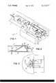
- FIG. 1is a perspective view of the equipment mount of the invention illustrating the two halves thereof separated from each other.
- FIG. 2is a cut-away side view of a portion of the equipment mount of the invention, showing the engagement of the locking member maintaining the relative positions of the first and second halves of the mount, taken at 2--2 in FIG. 3.
- FIG. 3is a plan view of a portion of the mounting apparatus of the invention, showing the spring lock engagement between the two halves thereof.
- the mounting appliance or apparatus 10 of the inventionis shown in FIG. 1, and includes first and second planar frames 11 and 12.
- the frame 11includes holes 14 by which it can be attached to a vehicle, for example, under the dash or other accessible location.
- the frame 12includes holes 16 for attachment to the equipment desired to be mounted, for example, a two way radio or the like, shown by dotted lines 18.
- the edges 19-19 of the frame 12are upwardly bent to define grooves 20-20 along opposite edges of the frame 12 to receive the top frame 11, as presently described.
- a spring locking member 22is fastened by a rivet 23 or the like to the frame 12.
- the spring locking member 23has a bias urging it in a normally upwardly direction, and is bent to present a curved upward ridge 26 to engage the upper frame 11, as described below.
- a member 30 attached to the frame 12, or formed as a part of it as illustrated,has a hole 31 through which a tongue portion 32 of the spring locking member extends. The walls of the hole 31 are of such spacing whereby the tongue 32 of the spring locking member 23 is constrained strictly to movement upwardly and downwardly from the frame 12.
- a handle portion 35can be included, as shown, as a part of the lower frame 12 to facilitate easy separation of the lower frame 12 and the equipment 18 carry thereby from the upward frame 11.
- the upward frame 11includes bends along its length to define wing portions 40-40 to enable the upper member 11 to slidingly engage lower member 12 within the grooves 20-20.
- An oblong slot 41is formed in a central location adjacent a forward edge 42 of the upper frame 11 for engagment with the spring locking member 22, as below described in detail.
- a plug meansis included having halves 45 and 46 respectively attached to the lower frame 12 and upper frame 11 to be brought into firm mating engagement when the upper frame 11 is in its forward sliding position with respect to the lower frame 12.
- the wires 48 from the plug half 45are attachable to various connections of the equipment 18, and the corresponding wires 49 of the plug half 46 are attachable to the various sources of the vehicle, such as the power supply, antenna, and the like.
- the spring locking member 22has its bend portion 26 extending slightly through the opening of the hole 41, thereby constraining the sliding movement of the upper frame 11 with respect to the lower frame 12 in the direction indicated by the arrow 50. Additionally, as can be seen in FIG. 3, in the engaged position, the bent portion 26 is designed whereby the edges of the spring locking member engage the opposite curved walls of the oblong hole 41, as indicated by the reference numerals 52-55.
- the transverse direction of travel, indicated by the arrow 58is additionally locked (the tongue portion 32 being constrained within the hole 31 of the upward member 30). Since the spring locking member 22 is biased normally upwardly, because of the positive engagement between the spring locking member and the walls of the hole 41, the upper frame 11 is urged upwardly, thereby urging the wing members 40-40 into engagement with the walls 19-19, thereby locking the relative up and down motion between the upper and lower frames 11 and 12.
- the relative motion between the upper and lower frames 11 and 12is constrained from motion in three transverse or orthogonal directions, thereby providing secure vibration free connection therebetween.
Landscapes
- Engineering & Computer Science (AREA)
- Mechanical Engineering (AREA)
- Fittings On The Vehicle Exterior For Carrying Loads, And Devices For Holding Or Mounting Articles (AREA)
Abstract
Description
1. Field of the Invention
This invention relates to improvements in equipment mounting apparatuses, and more particularly to improvements in locking means to maintain the relative positions of first and second equipment mounting frames in an engaged relationship.
2. Description of the Prior Art
Recently, with the increased interest in mobile communication equipment, such as Citizen's Band, amateur, and in fact, even commercial radio services, it has been becoming a widespread practice to remove the particular communication equipment vehicle in which it is used during periods of inactivity or non-use of the equipment to discourage its theft. To facilitate such easy removal, various mounting appliances have been proposed and used. Typically, such appliances employ first and second frames which have a facility enabling sliding engagement therebetween. Ordinarily, a plug which carries power supply and frequently microphone and antenna connections are brought into engagement when the frames are in operative position.
Nevertheless, such prior art frames have been unsatisfactory in many respects. Typically, the frames are inadequately locked one with respect to the other, resulting in excessive vibration and noise, and which, in fact, may have deleterious effects upon the connection plug, and constitute a general annoyance to the equipment user.
Although efforts have been made to insure that the mounting appliances, once in an operative position, do not slide apart, that is, lock in place along the axis of the sliding engagement, in so far as is known to applicant, no effort has been made to stabilize the relative movement between the parts of the appliance in directions transverse to the sliding direction.
In light of the above, it is therefore an object of the invention to provide apparatus for mounting equipment to a vehicle which enables rapid removal of the equipment with ease, and yet which firmly, solidly locks the equipment in place in use.
It is another object of the invention to provide a novel locking mechanism for maintaining the relative positions of first and second planar equipment carrying and mounting frames.
These and other objects, features, and advantages will become apparent to those skilled in the art from the following detailed description when read in conjunction with the accompanying drawings and appended claims.
In its broad aspect, the invention provides an apparatus for removably mounting equipment to a vehicle. The apparatus includes first and second generally planar frames, one of the frames being adapted for attachment to the equipment and the other of the frames being adapted for attachment to the vehicle. The edges of the second frame are formed to define grooves along opposite edges thereof, and the first frame has bends forming wings to enable its edges to be slideably received within the grooves of the second frame. Additionally, an oblong hole is formed in the first frame for receiving a locking member. A spring locking member is attached to the second frame at one end, and is biased in a direction away from the second frame in the direction of the first. The spring locking member has a bend to present a portion thereof to be received within the oblong hole, thereby urging the wings of the first member into engagement with the walls of the groove at the edges of the second member, locking the first and second frames against sliding relative movement. Additionally, in one embodiment of the invention, a member attached to the second frame extends in the direction of the first frame, and has a hole with walls engaging the spring locking member to constrain it from movement transverse to the sliding direction and to the direction in which the spring locking member is biased.
In the engaged positions, therefore, the first and second members are firmly locked against movement in three transverse directions by virtue of the spring member and its engagement within the oblong hole, together with the spring engaging member of the second frame.
The invention is illustrated in the accompanying drawing wherein:
FIG. 1 is a perspective view of the equipment mount of the invention illustrating the two halves thereof separated from each other.
FIG. 2 is a cut-away side view of a portion of the equipment mount of the invention, showing the engagement of the locking member maintaining the relative positions of the first and second halves of the mount, taken at 2--2 in FIG. 3.
And FIG. 3 is a plan view of a portion of the mounting apparatus of the invention, showing the spring lock engagement between the two halves thereof.
In the various figures of the drawing, like reference numerals are used to denote like parts.
The mounting appliance orapparatus 10 of the invention is shown in FIG. 1, and includes first and secondplanar frames frame 11 includes holes 14 by which it can be attached to a vehicle, for example, under the dash or other accessible location. Likewise, theframe 12 includesholes 16 for attachment to the equipment desired to be mounted, for example, a two way radio or the like, shown bydotted lines 18.
The edges 19-19 of theframe 12 are upwardly bent to define grooves 20-20 along opposite edges of theframe 12 to receive thetop frame 11, as presently described. Additionally, aspring locking member 22 is fastened by a rivet 23 or the like to theframe 12. The spring locking member 23 has a bias urging it in a normally upwardly direction, and is bent to present a curvedupward ridge 26 to engage theupper frame 11, as described below. Amember 30 attached to theframe 12, or formed as a part of it as illustrated, has ahole 31 through which atongue portion 32 of the spring locking member extends. The walls of thehole 31 are of such spacing whereby thetongue 32 of the spring locking member 23 is constrained strictly to movement upwardly and downwardly from theframe 12.
Optionally, ahandle portion 35 can be included, as shown, as a part of thelower frame 12 to facilitate easy separation of thelower frame 12 and theequipment 18 carry thereby from theupward frame 11.
Theupward frame 11 includes bends along its length to define wing portions 40-40 to enable theupper member 11 to slidingly engagelower member 12 within the grooves 20-20. Anoblong slot 41 is formed in a central location adjacent aforward edge 42 of theupper frame 11 for engagment with thespring locking member 22, as below described in detail.
Finally, a plug means is included havinghalves 45 and 46 respectively attached to thelower frame 12 andupper frame 11 to be brought into firm mating engagement when theupper frame 11 is in its forward sliding position with respect to thelower frame 12. The wires 48 from the plug half 45 are attachable to various connections of theequipment 18, and the corresponding wires 49 of theplug half 46 are attachable to the various sources of the vehicle, such as the power supply, antenna, and the like.
The details of the spring locking member and its engagement within theoblong hole 41 are shown in detail in FIGS. 2 and 3. As shown, thespring locking member 22 has itsbend portion 26 extending slightly through the opening of thehole 41, thereby constraining the sliding movement of theupper frame 11 with respect to thelower frame 12 in the direction indicated by thearrow 50. Additionally, as can be seen in FIG. 3, in the engaged position, thebent portion 26 is designed whereby the edges of the spring locking member engage the opposite curved walls of theoblong hole 41, as indicated by the reference numerals 52-55. By virtue of this engagement, in addition to reinforcing the locking action against the direction of slidingtravel 50, the transverse direction of travel, indicated by thearrow 58 is additionally locked (thetongue portion 32 being constrained within thehole 31 of the upward member 30). Since thespring locking member 22 is biased normally upwardly, because of the positive engagement between the spring locking member and the walls of thehole 41, theupper frame 11 is urged upwardly, thereby urging the wing members 40-40 into engagement with the walls 19-19, thereby locking the relative up and down motion between the upper andlower frames
Thus, in the sliding locked position, the relative motion between the upper andlower frames
Although the invention has been described and illustrated with a certain degree of particularity, it is understood that the present disclosure has been made only by way of example and that numerous changes in the details of construction and combination and arrangement of parts may be resorted to without departing from the spirit and scope of the invention as hereinafter claimed.
Claims (3)
1. Apparatus for removably mounting equipment to a vehicle, comprising:
first and second generally planar frames, one of said frames adapted for attachment to the equipment and another of said frames adapted for attachment to the vehicle,
members defining grooves along opposite edges of said second frame,
said first frame having bends to form wings slideably receivable in a direction along said grooves and having a centrally located oblong hole for receiving a spring locking member,
and a spring locking member biased in a direction away from and attached at an end to said second frame, having a bend for engagement with walls of said oblong hole adapted to engage said oblong hole at least at four opposing locations to constrain the motion therewithin in a direction transverse to said slideable direction, to urge said wings of said first into engagement with said grooves of said second frame to constrain any relative motion therebetween, and to lock said first and second frames against sliding relative movement.
2. Apparatus of claim 1 further comprising:
a member attached to said second frame extending in the direction of said first frame having a hole with walls engaging said spring member to constrain said spring member from movement transverse to said sliding direction and to said biased direction.
3. Apparatus of claim 2 further comprising plug means having mating halves respectively attached to said first and second frames to be held in firm mating engagement when said locking member is located within said oblong hole.
Priority Applications (1)
| Application Number | Priority Date | Filing Date | Title |
|---|---|---|---|
| US05/785,326US4113217A (en) | 1977-04-07 | 1977-04-07 | Apparatus for removably mounting equipment to a vehicle |
Applications Claiming Priority (1)
| Application Number | Priority Date | Filing Date | Title |
|---|---|---|---|
| US05/785,326US4113217A (en) | 1977-04-07 | 1977-04-07 | Apparatus for removably mounting equipment to a vehicle |
Publications (1)
| Publication Number | Publication Date |
|---|---|
| US4113217Atrue US4113217A (en) | 1978-09-12 |
Family
ID=25135132
Family Applications (1)
| Application Number | Title | Priority Date | Filing Date |
|---|---|---|---|
| US05/785,326Expired - LifetimeUS4113217A (en) | 1977-04-07 | 1977-04-07 | Apparatus for removably mounting equipment to a vehicle |
Country Status (1)
| Country | Link |
|---|---|
| US (1) | US4113217A (en) |
Cited By (51)
| Publication number | Priority date | Publication date | Assignee | Title |
|---|---|---|---|---|
| US4223921A (en)* | 1978-06-23 | 1980-09-23 | Cobe Laboratories, Inc. | Mount for supporting a medical device |
| US4256245A (en)* | 1979-10-26 | 1981-03-17 | Serres Paul J | Gun-mounting apparatus |
| US4346868A (en)* | 1980-05-19 | 1982-08-31 | Beatrice Foods Co., Div. Of Elgin Molded Plastics | Display device |
| FR2534204A1 (en)* | 1982-10-08 | 1984-04-13 | Roux Marc | Anti-theft system for motor vehicle loud speaker enclosures |
| GB2153902A (en)* | 1984-02-10 | 1985-08-29 | Ronald Michael Tipene | Securing devices |
| US4662664A (en)* | 1985-07-08 | 1987-05-05 | Mosinee Paper Corporation | Lock for paper towel dispenser cabinet |
| EP0249071A1 (en)* | 1986-06-10 | 1987-12-16 | Daimler-Benz Aktiengesellschaft | Anti-theft device for a car audio system built into a radio mounting shaft in a motor vehicle |
| EP0292751A3 (en)* | 1987-05-18 | 1989-04-05 | Stewart A. Roston | Bracket mount for automobile radar detector unit |
| FR2632584A1 (en)* | 1988-06-14 | 1989-12-15 | Mitsubishi Electric Corp | SYSTEM FOR THE REMOVABLE MOUNTING OF A PORTABLE DEVICE ON A MOTOR OR THE LIKE |
| FR2665591A1 (en)* | 1990-05-14 | 1992-02-07 | Motorola Inc | MOUNTING ASSEMBLY FOR TRANSCEIVER. |
| US5193052A (en)* | 1991-11-07 | 1993-03-09 | Advanced Matrix Technology, Inc. | Font cartridge extender with spring hook latch |
| US5435512A (en)* | 1992-12-24 | 1995-07-25 | The Whitaker Corporation | Mounting system for current mode coupler |
| US5488537A (en)* | 1994-03-28 | 1996-01-30 | Siemens Medical Systems, Inc. | Safety interconnect latch for portable medical electronic patient monitoring product |
| US5704660A (en)* | 1996-03-13 | 1998-01-06 | Ericsson Inc. | Locking fastener for enclosure cover |
| WO1998018654A1 (en)* | 1996-10-26 | 1998-05-07 | Robert Bosch Gmbh | Radio receiver |
| US5752918A (en)* | 1993-06-30 | 1998-05-19 | Medex, Inc. | Modular medical pressure transducer |
| US5820097A (en)* | 1997-01-10 | 1998-10-13 | Donnelly Corporation | Breakaway accessory mounting assembly for vehicles and windshield mounted button therefor |
| US5829723A (en)* | 1995-06-28 | 1998-11-03 | Medex, Inc. | Medical device mounting structure |
| US5868678A (en)* | 1993-06-30 | 1999-02-09 | Medex, Inc. | Two-part medical pressure transducer with diaphragm stand-offs |
| US6029940A (en)* | 1997-08-09 | 2000-02-29 | Hewlett-Packard Company | Support plate |
| US6029999A (en)* | 1997-04-19 | 2000-02-29 | O'day; John M. | Adjustable splash guard assembly |
| US6042068A (en)* | 1997-09-04 | 2000-03-28 | Peerless Indsutries, Inc. | Low profile LCD projector mount |
| US6129221A (en)* | 1998-07-29 | 2000-10-10 | Shaha; Kevin B. | Modular storage rack system |
| US6315255B1 (en)* | 1997-08-29 | 2001-11-13 | Nokia Mobile Phones Limited | Handset holder |
| US6530551B2 (en)* | 2001-06-15 | 2003-03-11 | Hon Hai Precision Ind. Co., Ltd. | Drive bracket fastening structure |
| US20050064864A1 (en)* | 2003-09-22 | 2005-03-24 | United Parcel Service Of America, Inc. | Symbiotic system for testing electromagnetic signal coverage in areas near transport routes |
| US20050075006A1 (en)* | 2003-09-24 | 2005-04-07 | United Parcel Service Of America, Inc. | Rapid exchange system for testing wireless networks |
| US20050101268A1 (en)* | 2003-09-22 | 2005-05-12 | United Parcel Service Of America, Inc. | Network testing systems and methods |
| US20060049321A1 (en)* | 2004-09-02 | 2006-03-09 | United Parcel Service Of America, Inc. | Rapid exchange system for testing wireless networks |
| US20060138783A1 (en)* | 2004-01-12 | 2006-06-29 | Maytag Corporation | Bidirectional slide lock and method of using same |
| EP1777111A1 (en)* | 2005-10-20 | 2007-04-25 | Robert Bosch Gmbh | Multifunctional mounting bracket for an electrical device |
| US20070243458A1 (en)* | 2006-04-07 | 2007-10-18 | Heiko Roehm | Battery pack |
| US20080024323A1 (en)* | 2006-07-25 | 2008-01-31 | Nagesh Kadaba | systems and methods for monitoring travel conditions |
| US20080129055A1 (en)* | 2006-12-04 | 2008-06-05 | Tyco Electronics Power Systems | Apparatus and method for holding a cover in a closed orientation |
| US20080128419A1 (en)* | 2006-11-30 | 2008-06-05 | Inventec Corporation | Lid fastening mechanism |
| US20080192418A1 (en)* | 2006-12-28 | 2008-08-14 | Bell'o International Corp. | Flat panel display mounting system |
| US20090090829A1 (en)* | 2006-04-18 | 2009-04-09 | Masafumi Yamamoto | Wall-mounted device and timepiece with the same |
| WO2011124296A3 (en)* | 2010-03-29 | 2011-12-15 | Festo Ag & Co. Kg | Sensor attachment device and associated sensor arrangement |
| US20120148341A1 (en)* | 2010-12-09 | 2012-06-14 | Samsung Electronics Co., Ltd. | Detachable fastening device for sliding module in sliding-type portable communication terminal |
| US8416067B2 (en) | 2008-09-09 | 2013-04-09 | United Parcel Service Of America, Inc. | Systems and methods for utilizing telematics data to improve fleet management operations |
| JP2014080069A (en)* | 2012-10-15 | 2014-05-08 | Denso Corp | On-vehicle device having fitting structure |
| US8794579B2 (en) | 2005-06-03 | 2014-08-05 | Steelcase, Inc. | Support arm assembly |
| US9156403B2 (en) | 2010-06-04 | 2015-10-13 | Magna Mirrors Of America, Inc. | Mirror mounting assembly with adapter |
| US9208626B2 (en) | 2011-03-31 | 2015-12-08 | United Parcel Service Of America, Inc. | Systems and methods for segmenting operational data |
| US9805521B1 (en) | 2013-12-03 | 2017-10-31 | United Parcel Service Of America, Inc. | Systems and methods for assessing turns made by a vehicle |
| US10309788B2 (en) | 2015-05-11 | 2019-06-04 | United Parcel Service Of America, Inc. | Determining street segment headings |
| DE102018203343A1 (en)* | 2018-03-07 | 2019-09-12 | BSH Hausgeräte GmbH | Interaction module |
| DE102018203347A1 (en)* | 2018-03-07 | 2019-09-12 | BSH Hausgeräte GmbH | Interaction module |
| US10713860B2 (en) | 2011-03-31 | 2020-07-14 | United Parcel Service Of America, Inc. | Segmenting operational data |
| US11482058B2 (en) | 2008-09-09 | 2022-10-25 | United Parcel Service Of America, Inc. | Systems and methods for utilizing telematics data to improve fleet management operations |
| US20230253734A1 (en)* | 2020-06-23 | 2023-08-10 | Otto Bock Healthcare Products Gmbh | Interface assembly |
Citations (6)
| Publication number | Priority date | Publication date | Assignee | Title |
|---|---|---|---|---|
| US517703A (en)* | 1894-04-03 | Spring-catch | ||
| US564661A (en)* | 1896-07-28 | Box-fastener | ||
| FR54014E (en)* | 1945-05-11 | 1947-03-27 | Raymond A | Improvements to clasps or similar fasteners |
| US3586394A (en)* | 1969-08-14 | 1971-06-22 | Kent Products Inc | Flexible plastic drawer-type receptacle guide |
| US3711140A (en)* | 1971-04-09 | 1973-01-16 | B Onori | Cabinet door latch |
| US3822049A (en)* | 1972-09-05 | 1974-07-02 | Automatic Radio Mfg Co | Anti-theft bracket device |
- 1977
- 1977-04-07USUS05/785,326patent/US4113217A/ennot_activeExpired - Lifetime
Patent Citations (6)
| Publication number | Priority date | Publication date | Assignee | Title |
|---|---|---|---|---|
| US517703A (en)* | 1894-04-03 | Spring-catch | ||
| US564661A (en)* | 1896-07-28 | Box-fastener | ||
| FR54014E (en)* | 1945-05-11 | 1947-03-27 | Raymond A | Improvements to clasps or similar fasteners |
| US3586394A (en)* | 1969-08-14 | 1971-06-22 | Kent Products Inc | Flexible plastic drawer-type receptacle guide |
| US3711140A (en)* | 1971-04-09 | 1973-01-16 | B Onori | Cabinet door latch |
| US3822049A (en)* | 1972-09-05 | 1974-07-02 | Automatic Radio Mfg Co | Anti-theft bracket device |
Cited By (97)
| Publication number | Priority date | Publication date | Assignee | Title |
|---|---|---|---|---|
| US4223921A (en)* | 1978-06-23 | 1980-09-23 | Cobe Laboratories, Inc. | Mount for supporting a medical device |
| US4256245A (en)* | 1979-10-26 | 1981-03-17 | Serres Paul J | Gun-mounting apparatus |
| US4346868A (en)* | 1980-05-19 | 1982-08-31 | Beatrice Foods Co., Div. Of Elgin Molded Plastics | Display device |
| FR2534204A1 (en)* | 1982-10-08 | 1984-04-13 | Roux Marc | Anti-theft system for motor vehicle loud speaker enclosures |
| GB2153902A (en)* | 1984-02-10 | 1985-08-29 | Ronald Michael Tipene | Securing devices |
| US4662664A (en)* | 1985-07-08 | 1987-05-05 | Mosinee Paper Corporation | Lock for paper towel dispenser cabinet |
| EP0249071A1 (en)* | 1986-06-10 | 1987-12-16 | Daimler-Benz Aktiengesellschaft | Anti-theft device for a car audio system built into a radio mounting shaft in a motor vehicle |
| EP0292751A3 (en)* | 1987-05-18 | 1989-04-05 | Stewart A. Roston | Bracket mount for automobile radar detector unit |
| FR2632584A1 (en)* | 1988-06-14 | 1989-12-15 | Mitsubishi Electric Corp | SYSTEM FOR THE REMOVABLE MOUNTING OF A PORTABLE DEVICE ON A MOTOR OR THE LIKE |
| US4930694A (en)* | 1988-06-14 | 1990-06-05 | Mitsubishi Denki Kabushiki Kaisha | Device mounting appliance |
| FR2665591A1 (en)* | 1990-05-14 | 1992-02-07 | Motorola Inc | MOUNTING ASSEMBLY FOR TRANSCEIVER. |
| US5193052A (en)* | 1991-11-07 | 1993-03-09 | Advanced Matrix Technology, Inc. | Font cartridge extender with spring hook latch |
| US5435512A (en)* | 1992-12-24 | 1995-07-25 | The Whitaker Corporation | Mounting system for current mode coupler |
| US5848971A (en)* | 1993-06-30 | 1998-12-15 | Medex, Inc. | Modular medical pressure transducer |
| US5868678A (en)* | 1993-06-30 | 1999-02-09 | Medex, Inc. | Two-part medical pressure transducer with diaphragm stand-offs |
| US5752918A (en)* | 1993-06-30 | 1998-05-19 | Medex, Inc. | Modular medical pressure transducer |
| US5488537A (en)* | 1994-03-28 | 1996-01-30 | Siemens Medical Systems, Inc. | Safety interconnect latch for portable medical electronic patient monitoring product |
| US5829723A (en)* | 1995-06-28 | 1998-11-03 | Medex, Inc. | Medical device mounting structure |
| US5704660A (en)* | 1996-03-13 | 1998-01-06 | Ericsson Inc. | Locking fastener for enclosure cover |
| WO1998018654A1 (en)* | 1996-10-26 | 1998-05-07 | Robert Bosch Gmbh | Radio receiver |
| US5820097A (en)* | 1997-01-10 | 1998-10-13 | Donnelly Corporation | Breakaway accessory mounting assembly for vehicles and windshield mounted button therefor |
| US6029999A (en)* | 1997-04-19 | 2000-02-29 | O'day; John M. | Adjustable splash guard assembly |
| US6029940A (en)* | 1997-08-09 | 2000-02-29 | Hewlett-Packard Company | Support plate |
| US6315255B1 (en)* | 1997-08-29 | 2001-11-13 | Nokia Mobile Phones Limited | Handset holder |
| US6042068A (en)* | 1997-09-04 | 2000-03-28 | Peerless Indsutries, Inc. | Low profile LCD projector mount |
| US6129221A (en)* | 1998-07-29 | 2000-10-10 | Shaha; Kevin B. | Modular storage rack system |
| US6530551B2 (en)* | 2001-06-15 | 2003-03-11 | Hon Hai Precision Ind. Co., Ltd. | Drive bracket fastening structure |
| US7773985B2 (en) | 2003-09-22 | 2010-08-10 | United Parcel Service Of America, Inc. | Symbiotic system for testing electromagnetic signal coverage in areas near transport routes |
| US8948742B2 (en) | 2003-09-22 | 2015-02-03 | United Parcel Service Of America, Inc. | Symbiotic system for testing electromagnetic signal coverage in areas near transport routes |
| US20050064864A1 (en)* | 2003-09-22 | 2005-03-24 | United Parcel Service Of America, Inc. | Symbiotic system for testing electromagnetic signal coverage in areas near transport routes |
| US7660577B2 (en) | 2003-09-22 | 2010-02-09 | United Parcel Service Of America, Inc. | Network testing systems and methods |
| US20110039498A1 (en)* | 2003-09-22 | 2011-02-17 | United Parcel Service Of America, Inc. | Symbiotic system for testing electromagnetic signal coverage in areas near transport routes |
| US20050101268A1 (en)* | 2003-09-22 | 2005-05-12 | United Parcel Service Of America, Inc. | Network testing systems and methods |
| US8374597B2 (en) | 2003-09-22 | 2013-02-12 | United Parcel Service Of America, Inc. | Symbiotic system for testing electromagnetic signal coverage in areas near transport routes |
| US8768342B2 (en) | 2003-09-22 | 2014-07-01 | United Parcel Service Of America, Inc. | Symbiotic system for testing electromagnetic signal coverage in areas near transport routes |
| US7431245B2 (en) | 2003-09-24 | 2008-10-07 | United Parcel Service Of America, Inc. | Rapid exchange system for testing wireless networks |
| US20050075105A1 (en)* | 2003-09-24 | 2005-04-07 | United Parcel Service Of America, Inc. | Rapid exchange system for testing wireless networks |
| US20050072888A1 (en)* | 2003-09-24 | 2005-04-07 | United Parcel Service Of America, Inc. | Rapid exchange system for testing wireless networks |
| US20050082077A1 (en)* | 2003-09-24 | 2005-04-21 | United Parcel Service Of America, Inc. | Rapid exchange system for testing wireless networks |
| US7059897B2 (en) | 2003-09-24 | 2006-06-13 | United Parcel Service Of America, Inc. | Rapid exchange system for testing wireless networks |
| US20050075006A1 (en)* | 2003-09-24 | 2005-04-07 | United Parcel Service Of America, Inc. | Rapid exchange system for testing wireless networks |
| US7810855B2 (en)* | 2004-01-12 | 2010-10-12 | Maytag Corporation | Bidirectional slide lock and method of using same |
| US20060138783A1 (en)* | 2004-01-12 | 2006-06-29 | Maytag Corporation | Bidirectional slide lock and method of using same |
| US20060049321A1 (en)* | 2004-09-02 | 2006-03-09 | United Parcel Service Of America, Inc. | Rapid exchange system for testing wireless networks |
| US7552901B2 (en) | 2004-09-02 | 2009-06-30 | United Parcel Service Of America, Inc. | Rapid exchange system for testing wireless networks |
| US8794579B2 (en) | 2005-06-03 | 2014-08-05 | Steelcase, Inc. | Support arm assembly |
| EP1777111A1 (en)* | 2005-10-20 | 2007-04-25 | Robert Bosch Gmbh | Multifunctional mounting bracket for an electrical device |
| US20080048076A1 (en)* | 2005-10-20 | 2008-02-28 | Ruud De Wit | Multifunctional mounting bracket for an electrical device |
| US7793901B2 (en) | 2005-10-20 | 2010-09-14 | Robert Bosch Gmbh | Multifunctional mounting bracket for an electrical device |
| US7879479B2 (en)* | 2006-04-07 | 2011-02-01 | Robert Bosch Gmbh | Battery pack utilizing integrally joined locking and holding means |
| US20070243458A1 (en)* | 2006-04-07 | 2007-10-18 | Heiko Roehm | Battery pack |
| US20090090829A1 (en)* | 2006-04-18 | 2009-04-09 | Masafumi Yamamoto | Wall-mounted device and timepiece with the same |
| US8245995B2 (en)* | 2006-04-18 | 2012-08-21 | Seiko Clock Inc. | Wall-mounted device and timepiece with the same |
| US7554440B2 (en) | 2006-07-25 | 2009-06-30 | United Parcel Service Of America, Inc. | Systems and methods for monitoring travel conditions |
| US20080024323A1 (en)* | 2006-07-25 | 2008-01-31 | Nagesh Kadaba | systems and methods for monitoring travel conditions |
| US20080128419A1 (en)* | 2006-11-30 | 2008-06-05 | Inventec Corporation | Lid fastening mechanism |
| US20080129055A1 (en)* | 2006-12-04 | 2008-06-05 | Tyco Electronics Power Systems | Apparatus and method for holding a cover in a closed orientation |
| US8789856B2 (en)* | 2006-12-04 | 2014-07-29 | General Electric Company | Apparatus and method for holding a cover in a closed orientation |
| US7726617B2 (en)* | 2006-12-28 | 2010-06-01 | Bell'o International Corp. | Flat panel display mounting system |
| US20080192418A1 (en)* | 2006-12-28 | 2008-08-14 | Bell'o International Corp. | Flat panel display mounting system |
| US9704303B2 (en) | 2008-09-09 | 2017-07-11 | United Parcel Service Of America, Inc. | Systems and methods for utilizing telematics data to improve fleet management operations |
| US11482058B2 (en) | 2008-09-09 | 2022-10-25 | United Parcel Service Of America, Inc. | Systems and methods for utilizing telematics data to improve fleet management operations |
| US8416067B2 (en) | 2008-09-09 | 2013-04-09 | United Parcel Service Of America, Inc. | Systems and methods for utilizing telematics data to improve fleet management operations |
| US10192370B2 (en) | 2008-09-09 | 2019-01-29 | United Parcel Service Of America, Inc. | Systems and methods for utilizing telematics data to improve fleet management operations |
| US8896430B2 (en) | 2008-09-09 | 2014-11-25 | United Parcel Service Of America, Inc. | Systems and methods for utilizing telematics data to improve fleet management operations |
| US9472030B2 (en) | 2008-09-09 | 2016-10-18 | United Parcel Service Of America, Inc. | Systems and methods for utilizing telematics data to improve fleet management operations |
| US9324198B2 (en) | 2008-09-09 | 2016-04-26 | United Parcel Service Of America, Inc. | Systems and methods for utilizing telematics data to improve fleet management operations |
| US10540830B2 (en) | 2008-09-09 | 2020-01-21 | United Parcel Service Of America, Inc. | Systems and methods for utilizing telematics data to improve fleet management operations |
| WO2011124296A3 (en)* | 2010-03-29 | 2011-12-15 | Festo Ag & Co. Kg | Sensor attachment device and associated sensor arrangement |
| CN102812336B (en)* | 2010-03-29 | 2016-05-11 | 费斯托股份有限两合公司 | Sensor fastening device and affiliated sensor cluster |
| CN102812336A (en)* | 2010-03-29 | 2012-12-05 | 费斯托股份有限两合公司 | Sensor attachment device and associated sensor arrangement |
| US9156403B2 (en) | 2010-06-04 | 2015-10-13 | Magna Mirrors Of America, Inc. | Mirror mounting assembly with adapter |
| US9475531B2 (en) | 2010-06-04 | 2016-10-25 | Magna Mirrors Of America, Inc. | Method of mounting an interior assembly with an adapter |
| US20120148341A1 (en)* | 2010-12-09 | 2012-06-14 | Samsung Electronics Co., Ltd. | Detachable fastening device for sliding module in sliding-type portable communication terminal |
| US10692037B2 (en) | 2011-03-31 | 2020-06-23 | United Parcel Service Of America, Inc. | Systems and methods for updating maps based on telematics data |
| US9256992B2 (en) | 2011-03-31 | 2016-02-09 | United Parcel Service Of America, Inc. | Systems and methods for assessing vehicle handling |
| US11727339B2 (en) | 2011-03-31 | 2023-08-15 | United Parcel Service Of America, Inc. | Systems and methods for updating maps based on telematics data |
| US9858732B2 (en) | 2011-03-31 | 2018-01-02 | United Parcel Service Of America, Inc. | Systems and methods for assessing vehicle and vehicle operator efficiency |
| US9903734B2 (en) | 2011-03-31 | 2018-02-27 | United Parcel Service Of America, Inc. | Systems and methods for updating maps based on telematics data |
| US11670116B2 (en) | 2011-03-31 | 2023-06-06 | United Parcel Service Of America, Inc. | Segmenting operational data |
| US9613468B2 (en) | 2011-03-31 | 2017-04-04 | United Parcel Service Of America, Inc. | Systems and methods for updating maps based on telematics data |
| US10267642B2 (en) | 2011-03-31 | 2019-04-23 | United Parcel Service Of America, Inc. | Systems and methods for assessing vehicle and vehicle operator efficiency |
| US9208626B2 (en) | 2011-03-31 | 2015-12-08 | United Parcel Service Of America, Inc. | Systems and methods for segmenting operational data |
| US11157861B2 (en) | 2011-03-31 | 2021-10-26 | United Parcel Service Of America, Inc. | Systems and methods for updating maps based on telematics data |
| US10748353B2 (en) | 2011-03-31 | 2020-08-18 | United Parcel Service Of America, Inc. | Segmenting operational data |
| US9799149B2 (en) | 2011-03-31 | 2017-10-24 | United Parcel Service Of America, Inc. | Fleet management computer system for providing a fleet management user interface displaying vehicle and operator data on a geographical map |
| US10563999B2 (en) | 2011-03-31 | 2020-02-18 | United Parcel Service Of America, Inc. | Systems and methods for assessing operational data for a vehicle fleet |
| US10713860B2 (en) | 2011-03-31 | 2020-07-14 | United Parcel Service Of America, Inc. | Segmenting operational data |
| JP2014080069A (en)* | 2012-10-15 | 2014-05-08 | Denso Corp | On-vehicle device having fitting structure |
| US10607423B2 (en) | 2013-12-03 | 2020-03-31 | United Parcel Service Of America, Inc. | Systems and methods for assessing turns made by a vehicle |
| US10055902B2 (en) | 2013-12-03 | 2018-08-21 | United Parcel Service Of America, Inc. | Systems and methods for assessing turns made by a vehicle |
| US9805521B1 (en) | 2013-12-03 | 2017-10-31 | United Parcel Service Of America, Inc. | Systems and methods for assessing turns made by a vehicle |
| US10309788B2 (en) | 2015-05-11 | 2019-06-04 | United Parcel Service Of America, Inc. | Determining street segment headings |
| DE102018203347A1 (en)* | 2018-03-07 | 2019-09-12 | BSH Hausgeräte GmbH | Interaction module |
| DE102018203343A1 (en)* | 2018-03-07 | 2019-09-12 | BSH Hausgeräte GmbH | Interaction module |
| US11448946B2 (en) | 2018-03-07 | 2022-09-20 | BSH Hausgeräte GmbH | Mounted projection system |
| US20230253734A1 (en)* | 2020-06-23 | 2023-08-10 | Otto Bock Healthcare Products Gmbh | Interface assembly |
Similar Documents
| Publication | Publication Date | Title |
|---|---|---|
| US4113217A (en) | Apparatus for removably mounting equipment to a vehicle | |
| US4419794A (en) | Portable fastening device | |
| US5022156A (en) | Handle fastener assembly and method of making same | |
| JPS5915107Y2 (en) | Mount for portable communication devices, etc. | |
| CA1313514C (en) | Housing and holder assembly for a portable communication apparatus | |
| US5450993A (en) | Carry holder | |
| US6622355B2 (en) | Mounting structure | |
| US4580754A (en) | Apparatus for mounting an appliance under a cabinet or the like | |
| US20060124679A1 (en) | Bicycle lock holding apparatus | |
| US7703500B2 (en) | Bracket and head rail assembly | |
| US4256245A (en) | Gun-mounting apparatus | |
| JPH04102560U (en) | Structure to prevent battery covers from falling off of wireless communication equipment, etc. | |
| US9781986B2 (en) | Holster for handheld radio | |
| US4326689A (en) | Mount for a housing which is releasably fastened to a wall | |
| US4127922A (en) | Latch device for a safety belt buckle in a vehicle and method of assembling the same | |
| JPS6114723Y2 (en) | ||
| JPH07323759A (en) | Retention assembly for mounting elements on vehicle instrument panel | |
| US4190840A (en) | Antenna mounting adaptor | |
| CN113844371B (en) | Holder for mobile electronic device | |
| JPH0245400Y2 (en) | ||
| JPS6237451Y2 (en) | ||
| JPS635265Y2 (en) | ||
| JPS5932156Y2 (en) | Leg system for small equipment | |
| JPS587995Y2 (en) | jack mounting device | |
| JPH0119805Y2 (en) |
Legal Events
| Date | Code | Title | Description |
|---|---|---|---|
| AS | Assignment | Owner name:WELLS FARGO CREDIT, INC., COLORADO Free format text:SECURITY INTEREST;ASSIGNOR:SYNERGY MANUFACTURING TECHNOLOGY, INC.;REEL/FRAME:014615/0747 Effective date:20030430 | |
| AS | Assignment | Owner name:SYNERGY MANUFACTURING TECHNOLOGY, INC., COLORADO Free format text:MERGER;ASSIGNOR:SCIENTIFIC DIMENSIONS, INC.;REEL/FRAME:014885/0272 Effective date:20020312 | |
| AS | Assignment | Owner name:SYNERGY MANUFACTURING TECHNOLOGY, INC., COLORADO Free format text:ASSIGNMENT OF ASSIGNORS INTEREST;ASSIGNOR:WELLS FARGO CREDIT, INC.;REEL/FRAME:016283/0010 Effective date:20050614 |