US4107039A - Dialysate preparation system - Google Patents
Dialysate preparation systemDownload PDFInfo
- Publication number
- US4107039A US4107039AUS05/674,621US67462176AUS4107039AUS 4107039 AUS4107039 AUS 4107039AUS 67462176 AUS67462176 AUS 67462176AUS 4107039 AUS4107039 AUS 4107039A
- Authority
- US
- United States
- Prior art keywords
- dialysate
- pressure
- piston
- water
- patient
- Prior art date
- Legal status (The legal status is an assumption and is not a legal conclusion. Google has not performed a legal analysis and makes no representation as to the accuracy of the status listed.)
- Expired - Lifetime
Links
Images


Classifications
- G—PHYSICS
- G05—CONTROLLING; REGULATING
- G05D—SYSTEMS FOR CONTROLLING OR REGULATING NON-ELECTRIC VARIABLES
- G05D16/00—Control of fluid pressure
- G05D16/04—Control of fluid pressure without auxiliary power
- G05D16/10—Control of fluid pressure without auxiliary power the sensing element being a piston or plunger
- A—HUMAN NECESSITIES
- A61—MEDICAL OR VETERINARY SCIENCE; HYGIENE
- A61M—DEVICES FOR INTRODUCING MEDIA INTO, OR ONTO, THE BODY; DEVICES FOR TRANSDUCING BODY MEDIA OR FOR TAKING MEDIA FROM THE BODY; DEVICES FOR PRODUCING OR ENDING SLEEP OR STUPOR
- A61M1/00—Suction or pumping devices for medical purposes; Devices for carrying-off, for treatment of, or for carrying-over, body-liquids; Drainage systems
- A61M1/14—Dialysis systems; Artificial kidneys; Blood oxygenators ; Reciprocating systems for treatment of body fluids, e.g. single needle systems for hemofiltration or pheresis
- A61M1/16—Dialysis systems; Artificial kidneys; Blood oxygenators ; Reciprocating systems for treatment of body fluids, e.g. single needle systems for hemofiltration or pheresis with membranes
- A61M1/1654—Dialysates therefor
- A61M1/1656—Apparatus for preparing dialysates
- A61M1/1657—Apparatus for preparing dialysates with centralised supply of dialysate or constituent thereof for more than one dialysis unit
- A—HUMAN NECESSITIES
- A61—MEDICAL OR VETERINARY SCIENCE; HYGIENE
- A61M—DEVICES FOR INTRODUCING MEDIA INTO, OR ONTO, THE BODY; DEVICES FOR TRANSDUCING BODY MEDIA OR FOR TAKING MEDIA FROM THE BODY; DEVICES FOR PRODUCING OR ENDING SLEEP OR STUPOR
- A61M1/00—Suction or pumping devices for medical purposes; Devices for carrying-off, for treatment of, or for carrying-over, body-liquids; Drainage systems
- A61M1/14—Dialysis systems; Artificial kidneys; Blood oxygenators ; Reciprocating systems for treatment of body fluids, e.g. single needle systems for hemofiltration or pheresis
- A61M1/16—Dialysis systems; Artificial kidneys; Blood oxygenators ; Reciprocating systems for treatment of body fluids, e.g. single needle systems for hemofiltration or pheresis with membranes
- A61M1/1654—Dialysates therefor
- A61M1/1656—Apparatus for preparing dialysates
- A61M1/166—Heating
- G—PHYSICS
- G05—CONTROLLING; REGULATING
- G05D—SYSTEMS FOR CONTROLLING OR REGULATING NON-ELECTRIC VARIABLES
- G05D16/00—Control of fluid pressure
- G05D16/024—Controlling the inlet pressure, e.g. back-pressure regulator
- Y—GENERAL TAGGING OF NEW TECHNOLOGICAL DEVELOPMENTS; GENERAL TAGGING OF CROSS-SECTIONAL TECHNOLOGIES SPANNING OVER SEVERAL SECTIONS OF THE IPC; TECHNICAL SUBJECTS COVERED BY FORMER USPC CROSS-REFERENCE ART COLLECTIONS [XRACs] AND DIGESTS
- Y10—TECHNICAL SUBJECTS COVERED BY FORMER USPC
- Y10T—TECHNICAL SUBJECTS COVERED BY FORMER US CLASSIFICATION
- Y10T137/00—Fluid handling
- Y10T137/2496—Self-proportioning or correlating systems
- Y10T137/2514—Self-proportioning flow systems
- Y10T137/2516—Interconnected flow displacement elements
- Y—GENERAL TAGGING OF NEW TECHNOLOGICAL DEVELOPMENTS; GENERAL TAGGING OF CROSS-SECTIONAL TECHNOLOGIES SPANNING OVER SEVERAL SECTIONS OF THE IPC; TECHNICAL SUBJECTS COVERED BY FORMER USPC CROSS-REFERENCE ART COLLECTIONS [XRACs] AND DIGESTS
- Y10—TECHNICAL SUBJECTS COVERED BY FORMER USPC
- Y10T—TECHNICAL SUBJECTS COVERED BY FORMER US CLASSIFICATION
- Y10T137/00—Fluid handling
- Y10T137/7722—Line condition change responsive valves
- Y10T137/7781—With separate connected fluid reactor surface
- Y10T137/7793—With opening bias [e.g., pressure regulator]
- Y10T137/7831—With mechanical movement between actuator and valve
Definitions
- This inventionrelates to dialysate preparation systems and more particularly to a system for supplying dialysate under pressure to a patient station or to multiple patient stations.
- the mixingcan also be done continuously at a central location which supplies dialysate to a number of patient stations.
- a central system for the continuous preparation and distribution of hemodialysis fluid"A central system for the continuous preparation and distribution of hemodialysis fluid," Grimsrud et al., Vol. X, Trans. Amer. Soc. Artif. Int. Organs, 1964, p. 107, describes such a central system. Dialysate must be supplied to each dialyzer at a constant pressure and at a temperature which is comfortable to the patient. In the aforesaid Grimsrud et al. system, a constant pressure is maintained by a head vessel. Further regulation is provided by a needle valve at each dialyzer. The temperature of the dialysate is controlled by two temperature controlled mixing valves at a central location.
- a head vesselhas the additional disadvantage of presenting a sanitation problem. Often, open vessels which are exposed to dust and bacteria in the air are used. Even closed head vessels have air pockets at the top thereof which expose the dialysate fluid to bacteria in the air. Often, head vessels have regions of little or no flow and in these regions, stagnant dialysate can become contaminated.
- dialysateis continuously prepared by mixing water under pressure with concentrate in a proportioning pump which produces dialysate under pressure.
- This dialysatecan be supplied on demand to the patient station.
- the pressure at which the dialysate is supplied to the patient stationis controlled by a pressure regulator.
- the dialysateis mixed cold at the central station and supplied to the patient stations where it is heated to the temperature desired by the individual patient.
- Pressure regulation under the widely varying flow requirements of the patient stationsis made possible by a unique regulator which controls a valve connected to a pressure sensing element. There is no flow interaction between the various units. The system provides almost instant response due to varying flow conditions, and it is insensitive to inlet water pressure changes.
- a constant force springprovides a constant bias for the pressure sensing element against water pressure over the entire range of movement of the pressure sensing element.
- the cold preparation, mixing and monitoring of dialysateis carried out in a module which is separate from the patient station itself. This is important in both multiple patient station systems and in single patient systems.
- the preparation system of this inventionhas the advantages of simple installation, reliable operation under widely varying patient demand conditions, clean, sanitary preparation without exposure of the dialysate and operation with normally available electrical distribution and plumbing systems.
- the system of this inventionmay be installed as a replacement for a number of existing single patient systems without changing the electrical or plumbing connections. Also, the system may be used to convert existing batch tank systems to proportioning systems.
- the present inventionprovides a modular system in which the user can select the type of patient station which is desired.
- Two examples of patient stations which are usable with the present inventionare those making use of coil or negative pressure dialyzers.
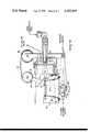
- FIG. 1shows a dialysate preparation system in accordance with this invention
- FIG. 2shows the pressure regulator
- FIG. 3shows the mixing vessel
- FIG. 4is a simplified electrical schematic diagram.
- FIG. 1shows a multiple station system.
- Water under pressure from a source 11is supplied through a regulator valve 12 to the four-way pump valve 13 and the free-piston proportioning pump 14.
- the wateris mixed with concentrate from the reservoir 15 in the correct proportions to form dialysate solution.
- the dialysatestill under the pressure regulated by the valve 12, is supplied to a closed mixing vessel 16.
- the pump valve 13 and free-piston proportioning pump 14are more fully described and claimed in copending application Ser. No. 547,625, filed Feb. 6, 1975. Briefly, the operation is as follows. With the valve 13 in the position shown, water pressure causes the large piston 17 in pump 14 to move toward the right. This forces a predetermined quantity of water on the right hand side of the piston 17 through the valve 13 and into the mixing vessel 16. Simultaneously, a predetermined volume of concentrate on the right hand side of the small piston 18 is forced through check valve 19 into the mixing vessel 16.
- a magnetic switch 23is actuated. This operates the valve 13 to its reverse position. With the valve in this position, water under pressure is applied to the right hand side of piston 17, thereby moving piston 17 toward the left. This forces a predetermined volume of water from the left hand side of the piston, through valve 13 to the mixing vessel 16. Simultaneously, a predetermined volume of concentrate is forced through check valve 24 to the mixing vessel 16. During this stroke of the piston, a precise volume of concentrate is drawn through the check valve 25 into the chamber on the right hand side of piston 18.
- a magnetic switch 26is actuated. This operates the valve 13 to its other position, thereby reversing movement of the piston and repeating the cycle previously described.
- the water driven double acting free-piston proportioning pumpis an important feature of the system because it provides an instantaneous response to changing flow demand.
- the pumpconstantly proportions at the correct ratio under varying demand conditions.
- a conductivity compensation thermistor probe 27 and a conductivity cell 28monitor the concentration of the dialysate.
- the dialysateis supplied to a constant pressure volume sensing chamber 29.
- a piston 30is exposed to constant pressure in the sensing chamber and moves linearly in response to the changing volume in this chamber.
- the pistonis connected by mechanical linkage to the regulator valve 12. Whenever the flow to the patient stations is not equal to the flow from the free-piston proportioning pump, the volume in the sensing chamber grows or shrinks due to the unequal flows. This volume change causes the piston to move the regulator valve which, in turn, varies the pump flow rate, until a balanced flow condition is established.
- a constant force spring assembly, indicated at 31,is connected to the piston to provide a constant bias against the pressure in the sensing chamber over the entire range of linear movement of the piston.
- the systemis capable of maintaining a constant pressure.
- the dialysateis connected through an electrically operated shut-off valve 32 to a manifold 33.
- the patient stationsare each connected directly to the constant pressure in the manifold 33.
- Each individual patient stationhas a heater for heating the dialysate to the desired temperature. Because the heaters are spread out, a normal electrical power distribution system is capable of handling the power requirements. Whereas a typical central dialysate preparation module requires a source of 220 volts power, the system of the present invention operates on 115 volts.
- the drain valve 34bypasses the dialysate to the drain when it is operated.
- both the shut-off valve 32 and the drain valve 34close, stopping all flow from the system.
- the shut-off valve 32is open and the drain valve 34 is closed.
- an alarm conditionoccurs, caused by an improper conductivity or pressure condition, for example, shut-off valve 32 is closed, stopping flow to the patient stations and drain valve 34 is opened to bypass the dialysate to drain.
- an overload (back pressure)valve 35is provided.
- the back pressure regulating valve 35opens to allow water to flow to drain.
- the back pressure valve 35can pass great quantities of water, if required, to prevent the pump 14 inlet pressure from rising significantly above the aforementioned predetermined level.
- a flow sensing switch 36is positioned in the drain path and is operated when water is flowing through the overload valve 35.
- a check valve 37is connected between the overload valve 35 and the drain valve 34 to prevent high pressure water from the overload valve being forced back to the patient stations if through inadvertence, the drain line becomes blocked.
- the flow switch 36is connected with two switches 37a and 37b which are actuated by the piston 30, to provide an alarm indication if there is low water pressure or if the system is being overloaded because the patient stations are demanding more dialysate than can be supplied at the desired pressure.
- the switchesare actuated when the volume sensing piston 30 is fully retracted; that is, there is low dialysate volume allowing the piston to move all the way to one extreme position.
- a stop switch 38is actuated when the volume sensing piston is fully extended to its other extreme position.
- the stop switch 38shuts off electrical power to the system only after the regulator valve 12 has been closed to cut off water supply to the system.
- the constant pressure regulatoris shown in FIG. 2.
- Water under pressureis supplied to a ball type regulator valve 39 having a regulator element which continuously changes the flow as the element is rotated.
- a linkage member 40operates the regulator element in the valve 39.
- the ball valvereduces the high inlet pressure to the pressure required to meet flow demand.
- the pressure applied to the proportioning pumpis the lowest possible for any given flow, thereby extending the wear life of the seals.
- a ball valveis particularly suitable for this purpose because its operating force (friction) is not significantly affected by changes in line pressure, thereby contributing to making the system output independent of inlet pressure.
- the linkage member 40is moved by a piston 41 which is exposed to dialysate pressure in the constant pressure volume sensing chamber 42.
- a relatively large volume of fluidis stored in the chamber 42. This storage capacity acts as an accumulator and provides flow on demand with no significant change in pressure.
- the pressure in the chamber 42is maintained constant regardless of the position of the piston 41, which position varies the flow rate. This is required when several patient stations are being operated from a single dialysate source to prevent flow changes at one station from causing changes in flow to other stations.
- the piston 41has a seal of the rolling diaphragm type.
- the use of such a sealhas the advantage of presenting no moving friction and making a contaminant proof barrier. Also, there is no way for dust or dirt to get into the stream of dialysate because no surface which is exposed to the air is ever exposed to the dialysate.
- the rolling diaphragmallows the piston 41 to pass over narrow slots in the enclosing cylinder without leaking. If a standard seal, such as an "O"-ring or a cup seal was used, the linkage could not extend through the cylinder where the piston moves and the regulator would be larger.
- One type of rolling diaphragmwhich is suitable for use is shown in U.S. Pat. No. 2,849,026.
- a constant force spring 43is connected to the linkage 40.
- One end of the spring 43is secured by the screw 44 to the non-rotating drum 45 on the linkage 40.
- the other end of spring 43is wound on the rotating drum 46.
- the linkage 40has a pin 47 which rides in a slot in the casing to guide the linkage.
- the linkage systemis designed so that the force on the piston is always a constant multiple of the spring force.
- a stop switch 38is positioned at one extreme end of travel to be actuated when the piston is fully extended.
- the switches 37a and 37b(not shown) are positioned at the other extreme position. They are actuated when the piston is at its extreme retracted position.
- the mixing vessel 16 shown in FIG. 3is a cylinder.
- a tee connector 48is at the bottom of the flat cylindrical side which is away from the view. Concentrate is supplied to one inlet of tee 48 and water is supplied to the other inlet of the tee.
- a concentrate injection nozzle 49 in the tee 48provides a high velocity continuous stream into the oncoming water thus causing turbulence to give good mixing.
- the mixing vessel 16provides a large enclosed volume to allow the concentrate and water to form a homogeneous dialysate solution. The vessel 16 is enclosed so dialysate pressure is maintained.
- the conductivity temperature compensation thermistor probe 27carries the temperature of the solution at the center of the cylinder. During periods when there is no dialysate flow out of the mixing vessel, the water rises to the top of the vessel and concentrate sinks to the bottom. However, the center of the cylinder has dialysate with the correct concentration. In order to take advantage of this, the outlet from the mixing vessel is taken from the center of the vessel. The tee 50 is connected at the center of the flat cylindrical face toward the viewer. The left hand of the tee is the outlet which is connected to the conductivity cell 28 (FIG. 1).
- FIG. 4is a simplified electrical diagram showing the electrical connections to the components previously described.
- the flow sensing switch 36 and the overload switch contacts 37a and 37bare connected to the overload, overload warning and low water pressure indicators and perform the following functions:
- the pressure regulator shown in FIG. 2is not used, but instead conventional pressure reducing valves are used. This provides a source of dialysate flow on demand but a variable pressure. As the patient load changes, the pressure regulators compensate for this changing condition and increase the flow through the proportioning pump. In this mode, there is a variation in pressure, but this is not significant for a single station because there is no other station flow to be affected by changing pressure.
- the important feature of this invention in this embodimentis the supply of dialysate on demand and at the correct concentration even after prolonged periods of non-use.
Landscapes
- Health & Medical Sciences (AREA)
- Urology & Nephrology (AREA)
- Heart & Thoracic Surgery (AREA)
- Engineering & Computer Science (AREA)
- Physics & Mathematics (AREA)
- Hematology (AREA)
- Public Health (AREA)
- Biomedical Technology (AREA)
- Vascular Medicine (AREA)
- Life Sciences & Earth Sciences (AREA)
- Animal Behavior & Ethology (AREA)
- General Health & Medical Sciences (AREA)
- Anesthesiology (AREA)
- Veterinary Medicine (AREA)
- Emergency Medicine (AREA)
- Fluid Mechanics (AREA)
- General Physics & Mathematics (AREA)
- Automation & Control Theory (AREA)
- External Artificial Organs (AREA)
Abstract
Description
__________________________________________________________________________ OVERLOADFLOW SENSING SWITCH 36 NO FLOW FLOW __________________________________________________________________________REGULA- OPEN System OK no alarms OVERLOAD warning audible & TOR LOW REGULATOR visual signals which can't OUTPUT OK be silenced. System PRESSURE continues to operate. SWITCHES CLOSED Low WATER PRESSURE OVERLOAD alarm -system 37a & REGULATOR alarm-system shuts shuts down. 37b STARVED down. __________________________________________________________________________
Claims (12)
Priority Applications (1)
| Application Number | Priority Date | Filing Date | Title |
|---|---|---|---|
| US05/674,621US4107039A (en) | 1976-04-07 | 1976-04-07 | Dialysate preparation system |
Applications Claiming Priority (1)
| Application Number | Priority Date | Filing Date | Title |
|---|---|---|---|
| US05/674,621US4107039A (en) | 1976-04-07 | 1976-04-07 | Dialysate preparation system |
Publications (1)
| Publication Number | Publication Date |
|---|---|
| US4107039Atrue US4107039A (en) | 1978-08-15 |
Family
ID=24707311
Family Applications (1)
| Application Number | Title | Priority Date | Filing Date |
|---|---|---|---|
| US05/674,621Expired - LifetimeUS4107039A (en) | 1976-04-07 | 1976-04-07 | Dialysate preparation system |
Country Status (1)
| Country | Link |
|---|---|
| US (1) | US4107039A (en) |
Cited By (21)
| Publication number | Priority date | Publication date | Assignee | Title |
|---|---|---|---|---|
| US4812239A (en)* | 1987-05-15 | 1989-03-14 | Cd Medical Inc. | Dry chemical mix system for hemodialysis |
| US5650071A (en)* | 1995-06-07 | 1997-07-22 | Cobe Laboratories, Inc. | Technique for priming and recirculating fluid through a dialysis machine to prepare the machine for use |
| US5972223A (en)* | 1994-09-20 | 1999-10-26 | Gambro Ab | Method and apparatus for the central preparation and distribution of salt concentrates |
| WO2002032476A3 (en)* | 2000-10-19 | 2002-08-22 | Nephros Inc | Method and apparatus for generating a sterile infusion fluid |
| US20090131859A1 (en)* | 2007-11-16 | 2009-05-21 | Baxter International Inc. | Flow pulsatility dampening devices for closed-loop controlled infusion systems |
| WO2010011442A3 (en)* | 2008-07-25 | 2010-03-18 | Baxter International Inc. | Dialysis system with flow regulation device |
| CN102481399A (en)* | 2009-06-15 | 2012-05-30 | 全达流体溶液有限公司 | Dialysis machine control |
| US8366667B2 (en) | 2010-02-11 | 2013-02-05 | Baxter International Inc. | Flow pulsatility dampening devices |
| US8894600B2 (en) | 2003-11-05 | 2014-11-25 | Baxter International Inc. | Hemodialysis system including on-line dialysate generation |
| US20170143886A1 (en)* | 2011-05-24 | 2017-05-25 | Deka Products Limited Partnership | Blood treatment systems and methods |
| US10098998B2 (en) | 2007-02-27 | 2018-10-16 | Deka Products Limited Partnership | Air trap for a medical infusion device |
| US10449280B2 (en) | 2007-02-27 | 2019-10-22 | Deka Products Limited Partnership | Hemodialysis systems and methods |
| US10463774B2 (en) | 2007-02-27 | 2019-11-05 | Deka Products Limited Partnership | Control systems and methods for blood or fluid handling medical devices |
| US10682450B2 (en) | 2007-02-27 | 2020-06-16 | Deka Products Limited Partnership | Blood treatment systems and methods |
| US11110212B2 (en) | 2007-02-27 | 2021-09-07 | Deka Products Limited Partnership | Blood circuit assembly for a hemodialysis system |
| US11253636B2 (en) | 2008-01-23 | 2022-02-22 | Deka Products Limited Partnership | Disposable components for fluid line autoconnect systems and methods |
| US11311656B2 (en) | 2007-02-27 | 2022-04-26 | Deka Products Limited Partnership | Modular assembly for a portable hemodialysis system |
| US11633526B2 (en) | 2007-02-27 | 2023-04-25 | Deka Products Limited Partnership | Cassette system integrated apparatus |
| US11833281B2 (en) | 2008-01-23 | 2023-12-05 | Deka Products Limited Partnership | Pump cassette and methods for use in medical treatment system using a plurality of fluid lines |
| US11890403B2 (en) | 2011-05-24 | 2024-02-06 | Deka Products Limited Partnership | Hemodialysis system |
| US20240277910A1 (en)* | 2011-03-23 | 2024-08-22 | Nxstage Medical, Inc. | Peritoneal Dialysis Systems, Devices, and Methods |
Citations (6)
| Publication number | Priority date | Publication date | Assignee | Title |
|---|---|---|---|---|
| US1202403A (en)* | 1914-08-25 | 1916-10-24 | John R Miller | Pressure-regulator. |
| US2804089A (en)* | 1955-03-24 | 1957-08-27 | Seifferle Oliver | Adjustable pressure regulating valve |
| US3032056A (en)* | 1957-04-01 | 1962-05-01 | Garrett Corp | Regulating valve |
| US3441136A (en)* | 1966-07-07 | 1969-04-29 | Milton Roy Co | Controlled blood dialysis system |
| US3598727A (en)* | 1969-04-07 | 1971-08-10 | Charles B Willock | Artificial kidney |
| US3605783A (en)* | 1966-03-17 | 1971-09-20 | Bio Systems Inc | Fluid mixing system |
- 1976
- 1976-04-07USUS05/674,621patent/US4107039A/ennot_activeExpired - Lifetime
Patent Citations (6)
| Publication number | Priority date | Publication date | Assignee | Title |
|---|---|---|---|---|
| US1202403A (en)* | 1914-08-25 | 1916-10-24 | John R Miller | Pressure-regulator. |
| US2804089A (en)* | 1955-03-24 | 1957-08-27 | Seifferle Oliver | Adjustable pressure regulating valve |
| US3032056A (en)* | 1957-04-01 | 1962-05-01 | Garrett Corp | Regulating valve |
| US3605783A (en)* | 1966-03-17 | 1971-09-20 | Bio Systems Inc | Fluid mixing system |
| US3441136A (en)* | 1966-07-07 | 1969-04-29 | Milton Roy Co | Controlled blood dialysis system |
| US3598727A (en)* | 1969-04-07 | 1971-08-10 | Charles B Willock | Artificial kidney |
Non-Patent Citations (3)
| Title |
|---|
| "A Central System for the Continuous Preparation and Distribution of Hemodialysis Fluid," Grimsrud et al., vol. X, Trans. Amer. Soc. Art. & Int. Organs, 1964, p. 107.* |
| "Human Factors in the Design of Artificial Kidney Machines," Published by The American Society of Mechanical Engineers, Nov. 1973.* |
| Specification Sheet of Seattle Artificial Kidney Supply Co., copyright 1972.* |
Cited By (42)
| Publication number | Priority date | Publication date | Assignee | Title |
|---|---|---|---|---|
| US4812239A (en)* | 1987-05-15 | 1989-03-14 | Cd Medical Inc. | Dry chemical mix system for hemodialysis |
| US5972223A (en)* | 1994-09-20 | 1999-10-26 | Gambro Ab | Method and apparatus for the central preparation and distribution of salt concentrates |
| US6113793A (en)* | 1994-09-20 | 2000-09-05 | Gambro Ab | Method of disinfecting an apparatus for the central preparation and distribution of salt concentrates |
| US6296762B1 (en) | 1994-09-20 | 2001-10-02 | Gambro Ab | Apparatus for disinfecting a device for the central preparation and distribution of salt concentrates |
| US5650071A (en)* | 1995-06-07 | 1997-07-22 | Cobe Laboratories, Inc. | Technique for priming and recirculating fluid through a dialysis machine to prepare the machine for use |
| US5776091A (en)* | 1995-06-07 | 1998-07-07 | Cobe Laboratories, Inc. | Technique for priming and recirculating fluid through a dialysis machine to prepare the machine for use |
| WO2002032476A3 (en)* | 2000-10-19 | 2002-08-22 | Nephros Inc | Method and apparatus for generating a sterile infusion fluid |
| US20040045881A1 (en)* | 2000-10-19 | 2004-03-11 | Collins Gregory R. | Method and apparatus for generating a sterile infusion fluid |
| US7108790B2 (en) | 2000-10-19 | 2006-09-19 | Nephros, Inc. | Method and apparatus for generating a sterile infusion fluid |
| US8894600B2 (en) | 2003-11-05 | 2014-11-25 | Baxter International Inc. | Hemodialysis system including on-line dialysate generation |
| US9302039B2 (en) | 2003-11-05 | 2016-04-05 | Baxter International Inc. | Hemodialysis system including a disposable cassette |
| US10183109B2 (en) | 2003-11-05 | 2019-01-22 | Baxter International Inc. | Hemodialysis system including a disposable cassette |
| US11633526B2 (en) | 2007-02-27 | 2023-04-25 | Deka Products Limited Partnership | Cassette system integrated apparatus |
| US11666690B2 (en) | 2007-02-27 | 2023-06-06 | Deka Products Limited Partnership | Blood treatment systems and methods |
| US11529444B2 (en) | 2007-02-27 | 2022-12-20 | Deka Products Limited Partnership | Blood treatment systems and methods |
| US11311656B2 (en) | 2007-02-27 | 2022-04-26 | Deka Products Limited Partnership | Modular assembly for a portable hemodialysis system |
| US11793915B2 (en) | 2007-02-27 | 2023-10-24 | Deka Products Limited Partnership | Hemodialysis systems and methods |
| US11752244B2 (en) | 2007-02-27 | 2023-09-12 | Deka Products Limited Partnership | Blood circuit assembly for a hemodialysis system |
| US10098998B2 (en) | 2007-02-27 | 2018-10-16 | Deka Products Limited Partnership | Air trap for a medical infusion device |
| US12005169B2 (en) | 2007-02-27 | 2024-06-11 | Deka Products Limited Partnership | Modular assembly for a portable hemodialysis system |
| US11154646B2 (en) | 2007-02-27 | 2021-10-26 | Deka Products Limited Partnership | Hemodialysis systems and methods |
| US11110212B2 (en) | 2007-02-27 | 2021-09-07 | Deka Products Limited Partnership | Blood circuit assembly for a hemodialysis system |
| US10449280B2 (en) | 2007-02-27 | 2019-10-22 | Deka Products Limited Partnership | Hemodialysis systems and methods |
| US10463774B2 (en) | 2007-02-27 | 2019-11-05 | Deka Products Limited Partnership | Control systems and methods for blood or fluid handling medical devices |
| US10682450B2 (en) | 2007-02-27 | 2020-06-16 | Deka Products Limited Partnership | Blood treatment systems and methods |
| US12059516B2 (en) | 2007-02-27 | 2024-08-13 | Deka Products Limited Partnership | Blood circuit assembly for a hemodialysis system |
| US8449500B2 (en) | 2007-11-16 | 2013-05-28 | Baxter International Inc. | Flow pulsatility dampening devices for closed-loop controlled infusion systems |
| US20090131859A1 (en)* | 2007-11-16 | 2009-05-21 | Baxter International Inc. | Flow pulsatility dampening devices for closed-loop controlled infusion systems |
| US11253636B2 (en) | 2008-01-23 | 2022-02-22 | Deka Products Limited Partnership | Disposable components for fluid line autoconnect systems and methods |
| US11833281B2 (en) | 2008-01-23 | 2023-12-05 | Deka Products Limited Partnership | Pump cassette and methods for use in medical treatment system using a plurality of fluid lines |
| US11511024B2 (en) | 2008-01-23 | 2022-11-29 | Deka Products Limited Partnership | Pump cassette and methods for use in medical treatment system using a plurality of fluid lines |
| US10265454B2 (en) | 2008-07-25 | 2019-04-23 | Baxter International Inc. | Dialysis system with flow regulation device |
| US11439736B2 (en) | 2008-07-25 | 2022-09-13 | Baxter International Inc. | Dialysis system with online dialysis fluid generation |
| EP3453413A3 (en)* | 2008-07-25 | 2019-06-19 | Baxter International Inc. | Dialysis system with flow regulation device |
| WO2010011442A3 (en)* | 2008-07-25 | 2010-03-18 | Baxter International Inc. | Dialysis system with flow regulation device |
| CN102481399A (en)* | 2009-06-15 | 2012-05-30 | 全达流体溶液有限公司 | Dialysis machine control |
| US8366667B2 (en) | 2010-02-11 | 2013-02-05 | Baxter International Inc. | Flow pulsatility dampening devices |
| US20240277910A1 (en)* | 2011-03-23 | 2024-08-22 | Nxstage Medical, Inc. | Peritoneal Dialysis Systems, Devices, and Methods |
| US11103625B2 (en) | 2011-05-24 | 2021-08-31 | Deka Products Limited Partnership | Blood treatment systems and methods |
| EP3263150A1 (en)* | 2011-05-24 | 2018-01-03 | DEKA Products Limited Partnership | Blood treatment systems and methods |
| US20170143886A1 (en)* | 2011-05-24 | 2017-05-25 | Deka Products Limited Partnership | Blood treatment systems and methods |
| US11890403B2 (en) | 2011-05-24 | 2024-02-06 | Deka Products Limited Partnership | Hemodialysis system |
Similar Documents
| Publication | Publication Date | Title |
|---|---|---|
| US4107039A (en) | Dialysate preparation system | |
| US3976574A (en) | Negative pressure control system | |
| CN1169034C (en) | Hydraulic actuating mixing valve | |
| US5623990A (en) | Temperature-controlled water delivery system | |
| US4977885A (en) | Hot water heating system with selective bypass | |
| US3731845A (en) | System for dispensing chilled carbonated water | |
| US4305547A (en) | Water heater temperature control system | |
| SE8504429D0 (en) | MIXING VALVE DEVICE | |
| JPS59164470A (en) | Thermostat mixing valve | |
| US7832651B2 (en) | Hydraulically controlled thermostatic mixing valve | |
| FI935506A0 (en) | Blandarvevil av enspakstyp foersedd med anordning Foer att foerebygga tryckstoet vid spakens staengningsroerelse | |
| US5169291A (en) | Water heater with shut-off valve | |
| US2224240A (en) | Hot wash water system | |
| CN209560354U (en) | A kind of high-performance liquid circuit heat control system | |
| US4991625A (en) | Multiple stream fluid mixing and dispensing apparatus | |
| US5427312A (en) | Thermostatic mixing valve and method of use thereof | |
| CN111045463A (en) | Anti-solidification constant temperature system for corn oil and constant temperature control method thereof | |
| US4653687A (en) | Mixing valve | |
| CN211847977U (en) | Automatic constant-temperature water replenishing device used in stem cell culture process | |
| US3454027A (en) | Proportional dispensing fluid handling system | |
| GB2200733A (en) | Instantaneous water heaters for showers | |
| GB742585A (en) | Improvements in and relating to thermally controlled valves | |
| GB2306631A (en) | Domestic water heating apparatus | |
| RU2121547C1 (en) | Circulating water supply system | |
| US3378027A (en) | Chemical additive system |
Legal Events
| Date | Code | Title | Description |
|---|---|---|---|
| AS | Assignment | Owner name:BAXTER TRAVENOL LABORATORIES, INC., ONE BAXTER PAR Free format text:ASSIGNMENT OF ASSIGNORS INTEREST.;ASSIGNOR:EXTRACORPOREAL MEDICAL SPECIALTIES, INC., A PA CORP;REEL/FRAME:004341/0250 Effective date:19840830 Owner name:BAXTER TRAVENOL LABORATORIES, INC.,ILLINOIS Free format text:ASSIGNMENT OF ASSIGNORS INTEREST;ASSIGNOR:EXTRACORPOREAL MEDICAL SPECIALTIES, INC., A PA CORP;REEL/FRAME:004341/0250 Effective date:19840830 | |
| AS | Assignment | Owner name:EXTRACORPOREAL MEDICAL SYSTEMS, INC., A CORP OF DE Free format text:CHANGE OF NAME;ASSIGNOR:EXTRACORPOREAL MEDICAL SYSTEMS, INC;REEL/FRAME:004327/0526 Effective date:19781211 Owner name:HARMAC INDUSTRIES, INC., A CORP OF NEW YORK Free format text:CHANGE OF NAME;ASSIGNOR:EXTRACORPOREAL MEDICAL SYSTEMS, INC;REEL/FRAME:004327/0526 Effective date:19781211 Owner name:VICELLON, INC., A CORP OF SOUTH CAROLINA MERGED IN Free format text:CHANGE OF NAME;ASSIGNOR:EXTRACORPOREAL MEDICAL SYSTEMS, INC;REEL/FRAME:004327/0526 Effective date:19781211 Owner name:LANZ MEDICAL PRODUCTS CORP A CORP OF PA Free format text:CHANGE OF NAME;ASSIGNOR:EXTRACORPOREAL MEDICAL SYSTEMS, INC;REEL/FRAME:004327/0526 Effective date:19781211 |