US4102558A - Non-shocking pin for fluorescent type tubes - Google Patents
Non-shocking pin for fluorescent type tubesDownload PDFInfo
- Publication number
- US4102558A US4102558AUS05/828,772US82877277AUS4102558AUS 4102558 AUS4102558 AUS 4102558AUS 82877277 AUS82877277 AUS 82877277AUS 4102558 AUS4102558 AUS 4102558A
- Authority
- US
- United States
- Prior art keywords
- pin
- body portion
- tip portion
- insulation
- terminal pin
- Prior art date
- Legal status (The legal status is an assumption and is not a legal conclusion. Google has not performed a legal analysis and makes no representation as to the accuracy of the status listed.)
- Expired - Lifetime
Links
- 238000009413insulationMethods0.000claimsabstractdescription18
- 239000011810insulating materialSubstances0.000claimsdescription3
- 239000004020conductorSubstances0.000claimsdescription2
- 230000035939shockEffects0.000abstractdescription11
- 239000003990capacitorSubstances0.000description4
- 239000000463materialSubstances0.000description3
- 230000009977dual effectEffects0.000description2
- 239000011521glassSubstances0.000description2
- 239000012774insulation materialSubstances0.000description2
- 229910001369BrassInorganic materials0.000description1
- RYGMFSIKBFXOCR-UHFFFAOYSA-NCopperChemical compound[Cu]RYGMFSIKBFXOCR-UHFFFAOYSA-N0.000description1
- 239000000853adhesiveSubstances0.000description1
- 230000001070adhesive effectEffects0.000description1
- 230000000712assemblyEffects0.000description1
- 238000000429assemblyMethods0.000description1
- 238000005452bendingMethods0.000description1
- 239000010951brassSubstances0.000description1
- 239000004568cementSubstances0.000description1
- 239000010949copperSubstances0.000description1
- 229910052802copperInorganic materials0.000description1
- 238000010292electrical insulationMethods0.000description1
- 238000004134energy conservationMethods0.000description1
- 238000007373indentationMethods0.000description1
- 238000003780insertionMethods0.000description1
- 230000037431insertionEffects0.000description1
- 238000009434installationMethods0.000description1
- 238000000034methodMethods0.000description1
- 229920003023plasticPolymers0.000description1
- 125000000391vinyl groupChemical group[H]C([*])=C([H])[H]0.000description1
- 229920002554vinyl polymerPolymers0.000description1
Images
Classifications
- H—ELECTRICITY
- H01—ELECTRIC ELEMENTS
- H01J—ELECTRIC DISCHARGE TUBES OR DISCHARGE LAMPS
- H01J5/00—Details relating to vessels or to leading-in conductors common to two or more basic types of discharge tubes or lamps
- H01J5/50—Means forming part of the tube or lamps for the purpose of providing electrical connection to it
Definitions
- the present inventionrelates to the field of terminal pins and end caps for fluorescent discharge tubes and tube substitutes, and in particular to terminal pins which prevent and reduce electrical shock hazard.
- Fluorescent discharge tubeshave long been used as an economical source of artificial light. These tubes comprise elongated glass envelope tubes and contain the electrically activated, light-generating elements with end caps at the ends thereof to seal the tube and provide means for making electrical contact with the electrical elements therein.
- One common type of end capis the bi-pin cap which utilizes a pair of pin terminals to connect to the corresponding lamp sockets. This type of end cap presents a shock hazard when the lamp is incorrectly installed and one end pin is left exposed out of the lamp holder. Also, if one end of an energized "hot" fluorescent tube is removed from its socket, a person inadvertently touching an exposed pin may be shocked.
- a hazardsimilarly exists with the so-called "dummy" tubes, i.e., tubes that contain no light generating elements, but rather contain simply a capacitor connecting one terminal pin at one end of the tube to the corresponding terminal pin at the other end, so as to provide electrical continuity between the lamp sockets without generating additional light.
- These tubeshave become increasingly used in situations where a dual tube assembly is used, and when, due to energy conservation measures or the like, only the light from, and power consumption of, a single fluorescent tube is desired.
- a shock hazardis presented when one end of the tube is placed in the energized lamp socket and the other end is exposed; since the capacitor presents essentially a short circuit between the two pins and inadvertent contact with the exposed pin will likely cause a shock.
- the capacitoracts as a current limiter and the magnitude of this shock is less than that of a fluorescent lamp.
- the subject inventiongreatly reduces the potential hazard of electrical shock, and provides a terminal pin compatible with conventional lamp sockets.
- a terminal pinfor use in connection with the bi-pin type end caps of fluorescent discharge tubes.
- a terminal pincomprises first and second body portions, separated by a projecting encircling boss, a tip portion of reduced thickness with respect to the body portions, and insulation covering substantially all the outer surface of the tip portion.
- the tip portionincludes a protrusion extending around the circumference of the tip acting as a retaining surface to prevent the insulation from slipping off the tip portion.
- the first body portion of the pinis inserted in an opening in the end cap having a size greater than the diameter of the pin body, but less than that of the boss.
- the bossengages the surface of the end cap and positively defines the length of the portion of the pin projecting from the cap.
- the pinsare compatible with conventional lamp sockets and present less electrically conductive area to persons handling the fluorescent tubes, thereby substantially reducing the shock hazard.
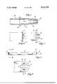
- FIG. 1is a cross-sectional view of the subject terminal pin, taken through an axial plane.
- FIG. 2is a perspective view of an end cap with the subject terminal pins installed on a fluorescent tube end cap.
- FIG. 3is a cross-sectional view of the end cap with a terminal pin installed.
- FIG. 4is an elevation view of a fluorescent discharge tube provided with the subject terminal pins, and a conventional lamp socket.
- FIG. 5is a view of the lamp socket, taken along line 5--5 shown in FIG. 4.
- FIG. 4shows a standard tubular fluorescent discharge lamp such as are in common use and available in various lengths.
- An end cap 10is used to fit over each end of the sealed lamp tube and provides an electrical connection with the lamp.
- two terminal pinsextend through spaced holes in each end cap, to which leads attached to the electrical elements are coupled.
- the end capsare inserted into lamp sockets such as are shown in FIG. 5, to connect a source of electrical energy to the discharge tube.
- These conventional lamp socketscomprise a body 15 of insulating material, having slot 19 and circular cavity 24 formed therein.
- Flatsided members 17are also formed of insulating material, and are typically integrally molded with body 15.
- Spring contacts 18comprise resilient, electrically energized conductors.
- the tube 23is aligned between the two lamp sockets so that the terminal pins of the end cap are in line with slots 19.
- the tubeis then manipulated so that the pins 20 are inserted through slot 19 into cavity 24.
- the tube 23is then rotated axially 90° so that the sides of terminal pins 20 engage contacts 18, which are formed with indentations into which the pins are engaged and locked (as shown in FIG. 5).
- Terminal pin 20is a hollow, elongated member of circular cross-section, comprising generally a first body portion 28, second body portion 29, and tip portion 30.
- Tip portion 30has a reduced cross-sectional diameter with respect to that of the second body portion 29.
- Encircling protrusion 32is formed around the periphery of the tip portion adjacent the second body portion 29.
- Encircling boss 40separates the first body portion 28 from the second body portion 29.
- Insulation material 50is installed around the tip portion 30 of the pin 20, covering substantially the entire outer surface thereof.
- This insulationis preferably a hard plastic or vinyl material and is subjected to a heat shrinking process so that the insulation shrinks to fit tightly around the tip portion 30. It is important that the maximum thickness of the insulation material and the diameter of the tip 30 be controlled so that the combined thickness of the tip portion with insulation does not exceed that of the second body portion 29 along the portions of the pin which make electrical contact with the connection.
- Protrusion 32serves to retain the insulation 50 in place and prevent its dislodging under an axially directed force. Of course, other means might be utilized to retain the insulation; for example, the surface of tip portion 30 might be roughened or knurled to form small gripping projections.
- End cap 10comprises a disclike member having annular flange 14 disposed around the periphery thereof.
- the inner diameter of the cap 10is selected to fit over the ends of the standard fluorescent tube.
- the cap 10is secured in place at the tube end with a suitable cement or adhesive.
- Openings 11are formed on a diametral line of the cap, and are formed with recesses 13 on the outer sides thereof; the diameter of opening 11 is larger than that of the first body portion of pin 20, and somewhat smaller than the outer diameter of boss 40.
- the first body portion 28 of the pin 20is inserted into opening 11 from the outer side of the cap 10. Since the external diameter of boss 40 is greater than the diameter of opening 11, boss 40 will contact the cap material surrounding opening 11 and prevent any further insertion of the pin 20. Thus, the length of the pin protruding from the outer surface of cap 10 is fixed by the location of boss 40. The depth of recess 13 is approximately to the depth of boss 40, so that boss 40 is substantially recessed below the exposed surface of cap 10, to prevent interference with lamp socket 15.
- the pin 20may be secured in position by splitting first body portion 28 extending from the cap 10 into lengthwise segments and bending these segments outward against the interior surface of the cap 10.
- Alternative securing meansmay be utilized to secure the pin in place, as for example, forcefitting the pin in opening 10, or threading the exterior surface of first pin portion 28 for threadable engagement with a tightening nut.
- the lead connecting to the electrical elements in the tube 14may be inserted into the hollow pin 20 and soldered in place.
- Pin 20is fabricated from materials having good conduction properties such as brass or copper.
- the spacing of holes 11is chosen so that the cap 10 with pins 20 may be utilized in connection with the conventional lamp sockets discussed hereinabove. Since the insulation 50 extends only along the tip portion 30, which portion has a reduced diameter with respect to second body portion 29, electrical contact may be made between a portion of the surface of second body portion 29 and contacts 18 of the lamp connector. As previously noted, the maximum thickness of the insulation is controlled so that contact with conducting second body portion 29 and electrical contact 18 is not prevented.
- the relative dimensions of the length of the tip portion 30 and the length of the second pin body 29can, of course, be selected to provide the maximum protection; sizes which have been found to provide good protection and still maintain good electrical contact between the pin and lamp socket are approximately 0.18 inches for the length of the second body portion and approximately 0.12 inches for the length of the tip portion. With these dimensions, the pin will provide sufficient contact with the conventional lamp sockets and the needed electrical insulation properties to prevent accidental shocks to persons installing or removing the lamps.
- dummy light tubesare often used in dual fluorescent discharge tube assemblies to provide electrical continuity between the lamp sockets, without generating additional light.
- These dummy tubestypically comprise a glass tube with end caps and terminals, the only internal electrical connection to the terminals being a capacitor connected between a corresponding terminal of each end cap. Terminal pins embodying the present invention may be used with the end caps of such dummy tubes to provide the electrical contact required.
Landscapes
- Common Detailed Techniques For Electron Tubes Or Discharge Tubes (AREA)
Abstract
Description
1. Field of the Invention:
The present invention relates to the field of terminal pins and end caps for fluorescent discharge tubes and tube substitutes, and in particular to terminal pins which prevent and reduce electrical shock hazard.
2. Description of Prior Art:
Fluorescent discharge tubes have long been used as an economical source of artificial light. These tubes comprise elongated glass envelope tubes and contain the electrically activated, light-generating elements with end caps at the ends thereof to seal the tube and provide means for making electrical contact with the electrical elements therein. One common type of end cap is the bi-pin cap which utilizes a pair of pin terminals to connect to the corresponding lamp sockets. This type of end cap presents a shock hazard when the lamp is incorrectly installed and one end pin is left exposed out of the lamp holder. Also, if one end of an energized "hot" fluorescent tube is removed from its socket, a person inadvertently touching an exposed pin may be shocked. A hazard similarly exists with the so-called "dummy" tubes, i.e., tubes that contain no light generating elements, but rather contain simply a capacitor connecting one terminal pin at one end of the tube to the corresponding terminal pin at the other end, so as to provide electrical continuity between the lamp sockets without generating additional light. These tubes have become increasingly used in situations where a dual tube assembly is used, and when, due to energy conservation measures or the like, only the light from, and power consumption of, a single fluorescent tube is desired. A shock hazard is presented when one end of the tube is placed in the energized lamp socket and the other end is exposed; since the capacitor presents essentially a short circuit between the two pins and inadvertent contact with the exposed pin will likely cause a shock. The capacitor acts as a current limiter and the magnitude of this shock is less than that of a fluorescent lamp.
In the past, this problem has not received much attention by the lamp manufacturers, and through careful use or experience, the number of people shocked was kept to a minimum. With the increased use of the dummy tubes and the advent of consumer protection awareness, additional attention has been focused on the shock hazards. The subject invention greatly reduces the potential hazard of electrical shock, and provides a terminal pin compatible with conventional lamp sockets.
An improved terminal pin for use in connection with the bi-pin type end caps of fluorescent discharge tubes is disclosed. A terminal pin comprises first and second body portions, separated by a projecting encircling boss, a tip portion of reduced thickness with respect to the body portions, and insulation covering substantially all the outer surface of the tip portion. The tip portion includes a protrusion extending around the circumference of the tip acting as a retaining surface to prevent the insulation from slipping off the tip portion. The first body portion of the pin is inserted in an opening in the end cap having a size greater than the diameter of the pin body, but less than that of the boss. The boss engages the surface of the end cap and positively defines the length of the portion of the pin projecting from the cap. The pins are compatible with conventional lamp sockets and present less electrically conductive area to persons handling the fluorescent tubes, thereby substantially reducing the shock hazard.
FIG. 1 is a cross-sectional view of the subject terminal pin, taken through an axial plane.
FIG. 2 is a perspective view of an end cap with the subject terminal pins installed on a fluorescent tube end cap.
FIG. 3 is a cross-sectional view of the end cap with a terminal pin installed.
FIG. 4 is an elevation view of a fluorescent discharge tube provided with the subject terminal pins, and a conventional lamp socket.
FIG. 5 is a view of the lamp socket, taken alongline 5--5 shown in FIG. 4.
Referring now to FIGS. 3, 4 and 5, the fluorescent tube, end cap, and lamp socket with which the subject invention may be utilized are shown. FIG. 4 shows a standard tubular fluorescent discharge lamp such as are in common use and available in various lengths. Anend cap 10 is used to fit over each end of the sealed lamp tube and provides an electrical connection with the lamp. To provide contact with the electrical elements within the tube, two terminal pins extend through spaced holes in each end cap, to which leads attached to the electrical elements are coupled. The end caps are inserted into lamp sockets such as are shown in FIG. 5, to connect a source of electrical energy to the discharge tube. These conventional lamp sockets comprise abody 15 of insulating material, havingslot 19 andcircular cavity 24 formed therein. Flatsidedmembers 17 are also formed of insulating material, and are typically integrally molded withbody 15.Spring contacts 18 comprise resilient, electrically energized conductors. Thetube 23 is aligned between the two lamp sockets so that the terminal pins of the end cap are in line withslots 19. The tube is then manipulated so that thepins 20 are inserted throughslot 19 intocavity 24. Thetube 23 is then rotated axially 90° so that the sides ofterminal pins 20 engagecontacts 18, which are formed with indentations into which the pins are engaged and locked (as shown in FIG. 5).
Referring now to FIG. 1, an axial cross-sectional view of the preferred embodiment of the subject invention is shown.Terminal pin 20 is a hollow, elongated member of circular cross-section, comprising generally afirst body portion 28,second body portion 29, andtip portion 30.Tip portion 30 has a reduced cross-sectional diameter with respect to that of thesecond body portion 29.Encircling protrusion 32 is formed around the periphery of the tip portion adjacent thesecond body portion 29. Encirclingboss 40 separates thefirst body portion 28 from thesecond body portion 29.
A pair of theterminal pins 20 is inserted into spaced openings 11 formed inend cap 10.End cap 10 comprises a disclike member havingannular flange 14 disposed around the periphery thereof. The inner diameter of thecap 10 is selected to fit over the ends of the standard fluorescent tube. Thecap 10 is secured in place at the tube end with a suitable cement or adhesive. Openings 11 are formed on a diametral line of the cap, and are formed withrecesses 13 on the outer sides thereof; the diameter of opening 11 is larger than that of the first body portion ofpin 20, and somewhat smaller than the outer diameter ofboss 40.
Thefirst body portion 28 of thepin 20 is inserted into opening 11 from the outer side of thecap 10. Since the external diameter ofboss 40 is greater than the diameter of opening 11,boss 40 will contact the cap material surrounding opening 11 and prevent any further insertion of thepin 20. Thus, the length of the pin protruding from the outer surface ofcap 10 is fixed by the location ofboss 40. The depth ofrecess 13 is approximately to the depth ofboss 40, so thatboss 40 is substantially recessed below the exposed surface ofcap 10, to prevent interference withlamp socket 15. Thepin 20 may be secured in position by splittingfirst body portion 28 extending from thecap 10 into lengthwise segments and bending these segments outward against the interior surface of thecap 10. Alternative securing means may be utilized to secure the pin in place, as for example, forcefitting the pin in opening 10, or threading the exterior surface offirst pin portion 28 for threadable engagement with a tightening nut. The lead connecting to the electrical elements in thetube 14 may be inserted into thehollow pin 20 and soldered in place.Pin 20 is fabricated from materials having good conduction properties such as brass or copper.
The spacing of holes 11 is chosen so that thecap 10 withpins 20 may be utilized in connection with the conventional lamp sockets discussed hereinabove. Since theinsulation 50 extends only along thetip portion 30, which portion has a reduced diameter with respect tosecond body portion 29, electrical contact may be made between a portion of the surface ofsecond body portion 29 andcontacts 18 of the lamp connector. As previously noted, the maximum thickness of the insulation is controlled so that contact with conductingsecond body portion 29 andelectrical contact 18 is not prevented.
It has been found that the hazard of electrical shock from touching the terminal pins of fluorescent discharge tubes during installation is greatly reduced, if not eliminated, by the placement of the insulation around the tip portion of thepin 20. The relative dimensions of the length of thetip portion 30 and the length of thesecond pin body 29 can, of course, be selected to provide the maximum protection; sizes which have been found to provide good protection and still maintain good electrical contact between the pin and lamp socket are approximately 0.18 inches for the length of the second body portion and approximately 0.12 inches for the length of the tip portion. With these dimensions, the pin will provide sufficient contact with the conventional lamp sockets and the needed electrical insulation properties to prevent accidental shocks to persons installing or removing the lamps.
Of course, the invention may be used in other ways and for other devices. For example, dummy light tubes are often used in dual fluorescent discharge tube assemblies to provide electrical continuity between the lamp sockets, without generating additional light. These dummy tubes typically comprise a glass tube with end caps and terminals, the only internal electrical connection to the terminals being a capacitor connected between a corresponding terminal of each end cap. Terminal pins embodying the present invention may be used with the end caps of such dummy tubes to provide the electrical contact required.
Although this invention has been disclosed and described with reference to particular embodiments, the principles involved are susceptible of other applications which will be apparent to persons skilled in the art. This invention, therefore, is not intended to be limited to the particular embodiment herein described. Various changes in the form, detail and application of the subject terminal pin may be made therein without departing from the spirit and scope of the invention.
Claims (12)
1. The terminal pin of electrically conducting material for use with end caps of fluorescent discharge tubes and the like comprising:
an elongated pin body portion;
a tip portion extending from an end of said body portion, said tip portion having a reduced thickness with respect to that of said body portion; and
insulation covering substantially all the exterior surface of said tip portion.
2. The terminal pin of claim 1 wherein said tip portion includes a projection covered by said insulation, wherein said projection tends to prevent removal of said insulation by an axially directed force.
3. The terminal pin of claim 1 wherein said pin body portion is divided into a first body portion and a second body portion by a projecting member.
4. The terminal pin of claim 3 wherein said projecting member comprises an encircling boss.
5. The terminal pin of claim 1 wherein said pin body is hollow.
6. The terminal pin for use with end caps of fluorescent discharge tubes and the like comprising:
a hollow, elongated pin body having a circular cross-section, divided into a first body portion and a second body portion by an encircling boss;
a tip portion extending from an end of said body portion, said tip portion having a reduced thickness with respect to that of said body portion, and further including an encircling projection; and
non-conducting insulating material covering substantially the entire exterior surface of said tip portion.
7. The connector end cap for fluorescent discharge tubes and the like comprising:
disc member having an annular flange disposed around the periphery thereof;
a pair of openings formed in said disc member;
a pair of terminal pins, one each inserted through each of said openings, each of said pins having an elongated body portion and a tip portion extending from an end of said body portion having a reduced thickness with respect to that of said body portion;
insulation for covering substantially all the exterior surface of said tip portion; and means for securing said pin in said opening;
whereby the electrical elements within said tube may be electrically coupled to said pins for connection to a source of electrical energy, and said insulation reduces the electrically conducting surface area of said pin exposed to persons handling such tubes.
8. The end cap of claim 6 wherein said tip portion of said pin includes a projection covered by said insulation, wherein said projection tends to prevent removal of said insulation by an axially directed force.
9. The terminal pin of claim 7 wherein said pin body is hollow.
10. The terminal pin of claim 7 wherein said pin body portion is divided into a first body portion and a second body portion by a projecting member.
11. The terminal pin of claim 10 wherein said projecting member comprises an encircling boss.
12. The end cap of claim 11 wherein recesses are provided in said disc member adjacent said openings for receiving said bosses.
Priority Applications (1)
| Application Number | Priority Date | Filing Date | Title |
|---|---|---|---|
| US05/828,772US4102558A (en) | 1977-08-29 | 1977-08-29 | Non-shocking pin for fluorescent type tubes |
Applications Claiming Priority (1)
| Application Number | Priority Date | Filing Date | Title |
|---|---|---|---|
| US05/828,772US4102558A (en) | 1977-08-29 | 1977-08-29 | Non-shocking pin for fluorescent type tubes |
Publications (1)
| Publication Number | Publication Date |
|---|---|
| US4102558Atrue US4102558A (en) | 1978-07-25 |
Family
ID=25252707
Family Applications (1)
| Application Number | Title | Priority Date | Filing Date |
|---|---|---|---|
| US05/828,772Expired - LifetimeUS4102558A (en) | 1977-08-29 | 1977-08-29 | Non-shocking pin for fluorescent type tubes |
Country Status (1)
| Country | Link |
|---|---|
| US (1) | US4102558A (en) |
Cited By (60)
| Publication number | Priority date | Publication date | Assignee | Title |
|---|---|---|---|---|
| US4326146A (en)* | 1980-04-02 | 1982-04-20 | Westinghouse Electric Corp. | Base and terminal-pin assembly for electric lamps and similar devices |
| US4855634A (en)* | 1985-12-19 | 1989-08-08 | Gte Products Corporation | Reflector and eyelet construction for reflector-type lamps |
| US4854888A (en)* | 1988-05-31 | 1989-08-08 | Gte Products Corporation | Lamp base |
| US4878854A (en)* | 1988-05-31 | 1989-11-07 | Gte Products Corporation | Lamp base |
| US4912371A (en)* | 1989-02-27 | 1990-03-27 | Hamilton William L | Power saving fluorescent lamp substitute |
| EP0281079A3 (en)* | 1987-03-05 | 1990-06-27 | Kabushiki Kaisha Toshiba | Low pressure discharge lamp |
| US5600199A (en)* | 1994-09-15 | 1997-02-04 | Martin, Sr.; Steve E. | Fluorescent lamp with spring-loaded terminal pins |
| US20030155852A1 (en)* | 2002-02-15 | 2003-08-21 | Osram Sylvania Inc. | Fluorescent lamp and method for mounting an insulator disk thereon |
| US6632100B1 (en) | 1997-04-23 | 2003-10-14 | Anthony, Inc. | Lighting system method and apparatus socket assembly lamp insulator assembly and components thereof |
| US6641419B1 (en) | 1997-08-29 | 2003-11-04 | Anthony, Inc. | Lighting circuit, lighting system method and apparatus, socket assembly, lamp insulator assembly and components thereof |
| US20050136754A1 (en)* | 2003-12-17 | 2005-06-23 | Wilson Carolyn E. | Seamed pin for crimping and welding as used in a fluorescent lamp |
| US20050162093A1 (en)* | 2000-02-11 | 2005-07-28 | Jos Timmermans | Light tube and power supply circuit |
| US20060193131A1 (en)* | 2005-02-28 | 2006-08-31 | Mcgrath William R | Circuit devices which include light emitting diodes, assemblies which include such circuit devices, and methods for directly replacing fluorescent tubes |
| US20070066112A1 (en)* | 2005-09-13 | 2007-03-22 | Anthony Tufano | Fluorescent lampholder |
| US20090159919A1 (en)* | 2007-12-20 | 2009-06-25 | Altair Engineering, Inc. | Led lighting apparatus with swivel connection |
| US20090290334A1 (en)* | 2008-05-23 | 2009-11-26 | Altair Engineering, Inc. | Electric shock resistant l.e.d. based light |
| US20100008085A1 (en)* | 2008-07-09 | 2010-01-14 | Altair Engineering, Inc. | Method of forming led-based light and resulting led-based light |
| US20100013391A1 (en)* | 2008-07-15 | 2010-01-21 | Leviton Manufacturing Corporation | Fluorescent lamp support |
| US20100027259A1 (en)* | 2008-07-31 | 2010-02-04 | Altair Engineering, Inc. | Fluorescent tube replacement having longitudinally oriented leds |
| US20100052542A1 (en)* | 2008-09-02 | 2010-03-04 | Altair Engineering, Inc. | Led lamp failure alerting system |
| US20100067231A1 (en)* | 2008-09-15 | 2010-03-18 | Altair Engineering, Inc. | Led-based light having rapidly oscillating leds |
| US20100081339A1 (en)* | 2008-10-01 | 2010-04-01 | Leviton Manufacturing Company, Inc. | Lamp socket having a rotor assembly |
| US20100106306A1 (en)* | 2008-10-24 | 2010-04-29 | Altair Engineering, Inc. | Integration of led lighting with building controls |
| US20100102960A1 (en)* | 2008-10-24 | 2010-04-29 | Altair Engineering, Inc. | Integration of led lighting control with emergency notification systems |
| US20100102730A1 (en)* | 2008-10-24 | 2010-04-29 | Altair Engineering, Inc. | Light and light sensor |
| US20100103673A1 (en)* | 2008-10-24 | 2010-04-29 | Altair Engineering, Inc. | End cap substitute for led-based tube replacement light |
| US20100103664A1 (en)* | 2008-10-24 | 2010-04-29 | Altair Engineering, Inc. | Lighting including integral communication apparatus |
| US20100172149A1 (en)* | 2007-12-21 | 2010-07-08 | Altair Engineering, Inc. | Light distribution using a light emitting diode assembly |
| US20100177532A1 (en)* | 2009-01-15 | 2010-07-15 | Altair Engineering, Inc. | Led lens |
| US20100181933A1 (en)* | 2009-01-21 | 2010-07-22 | Altair Engineering, Inc. | Direct ac-to-dc converter for passive component minimization and universal operation of led arrays |
| US20100181925A1 (en)* | 2009-01-21 | 2010-07-22 | Altair Engineering, Inc. | Ballast/Line Detection Circuit for Fluorescent Replacement Lamps |
| US20100220469A1 (en)* | 2008-05-23 | 2010-09-02 | Altair Engineering, Inc. | D-shaped cross section l.e.d. based light |
| US20100265700A1 (en)* | 2008-07-15 | 2010-10-21 | Leviton Manufacturing Corporation | Flourescent lamp support |
| US20100320922A1 (en)* | 2009-06-23 | 2010-12-23 | Altair Engineering, Inc. | Illumination device including leds and a switching power control system |
| US20100321921A1 (en)* | 2009-06-23 | 2010-12-23 | Altair Engineering, Inc. | Led lamp with a wavelength converting layer |
| US20110164414A1 (en)* | 2008-07-15 | 2011-07-07 | Robert Quercia | Fluorescent lamp support |
| US20110235318A1 (en)* | 2010-03-26 | 2011-09-29 | Altair Engineering, Inc. | Led light tube with dual sided light distribution |
| US8093823B1 (en)* | 2000-02-11 | 2012-01-10 | Altair Engineering, Inc. | Light sources incorporating light emitting diodes |
| US8299695B2 (en) | 2009-06-02 | 2012-10-30 | Ilumisys, Inc. | Screw-in LED bulb comprising a base having outwardly projecting nodes |
| US8330381B2 (en) | 2009-05-14 | 2012-12-11 | Ilumisys, Inc. | Electronic circuit for DC conversion of fluorescent lighting ballast |
| US8333602B2 (en) | 2011-01-06 | 2012-12-18 | Leviton Manufacturing Co., Inc. | Lamp socket having a rotor |
| US8454193B2 (en) | 2010-07-08 | 2013-06-04 | Ilumisys, Inc. | Independent modules for LED fluorescent light tube replacement |
| US8523394B2 (en) | 2010-10-29 | 2013-09-03 | Ilumisys, Inc. | Mechanisms for reducing risk of shock during installation of light tube |
| US8540401B2 (en) | 2010-03-26 | 2013-09-24 | Ilumisys, Inc. | LED bulb with internal heat dissipating structures |
| US8541958B2 (en) | 2010-03-26 | 2013-09-24 | Ilumisys, Inc. | LED light with thermoelectric generator |
| US8596813B2 (en) | 2010-07-12 | 2013-12-03 | Ilumisys, Inc. | Circuit board mount for LED light tube |
| US8870415B2 (en) | 2010-12-09 | 2014-10-28 | Ilumisys, Inc. | LED fluorescent tube replacement light with reduced shock hazard |
| US8901823B2 (en) | 2008-10-24 | 2014-12-02 | Ilumisys, Inc. | Light and light sensor |
| US9072171B2 (en) | 2011-08-24 | 2015-06-30 | Ilumisys, Inc. | Circuit board mount for LED light |
| US9163794B2 (en) | 2012-07-06 | 2015-10-20 | Ilumisys, Inc. | Power supply assembly for LED-based light tube |
| US9184518B2 (en) | 2012-03-02 | 2015-11-10 | Ilumisys, Inc. | Electrical connector header for an LED-based light |
| US9267650B2 (en) | 2013-10-09 | 2016-02-23 | Ilumisys, Inc. | Lens for an LED-based light |
| US9271367B2 (en) | 2012-07-09 | 2016-02-23 | Ilumisys, Inc. | System and method for controlling operation of an LED-based light |
| US9285084B2 (en) | 2013-03-14 | 2016-03-15 | Ilumisys, Inc. | Diffusers for LED-based lights |
| US20160327216A1 (en)* | 2014-01-13 | 2016-11-10 | Philips Lighting Holding B.V. | Led tube for retrofitting in a fluorescent tube lighting fixture |
| US9510400B2 (en) | 2014-05-13 | 2016-11-29 | Ilumisys, Inc. | User input systems for an LED-based light |
| US9574717B2 (en) | 2014-01-22 | 2017-02-21 | Ilumisys, Inc. | LED-based light with addressed LEDs |
| USD803785S1 (en) | 2016-02-19 | 2017-11-28 | Dinesh Wadhwani | Electric lamp socket |
| US9879831B2 (en)* | 2016-03-02 | 2018-01-30 | Ledvance Gmbh | Semiconductor lamp with tubular contact pins |
| US10161568B2 (en) | 2015-06-01 | 2018-12-25 | Ilumisys, Inc. | LED-based light with canted outer walls |
Citations (3)
| Publication number | Priority date | Publication date | Assignee | Title |
|---|---|---|---|---|
| US2385340A (en)* | 1943-01-02 | 1945-09-25 | Sylvania Electric Prod | Electrical device |
| US2680236A (en)* | 1950-08-22 | 1954-06-01 | Gen Electric | Crimped contact pin assembly |
| US3855495A (en)* | 1973-11-05 | 1974-12-17 | Gte Sylvania Inc | Flash tube with insulator end cap |
- 1977
- 1977-08-29USUS05/828,772patent/US4102558A/ennot_activeExpired - Lifetime
Patent Citations (3)
| Publication number | Priority date | Publication date | Assignee | Title |
|---|---|---|---|---|
| US2385340A (en)* | 1943-01-02 | 1945-09-25 | Sylvania Electric Prod | Electrical device |
| US2680236A (en)* | 1950-08-22 | 1954-06-01 | Gen Electric | Crimped contact pin assembly |
| US3855495A (en)* | 1973-11-05 | 1974-12-17 | Gte Sylvania Inc | Flash tube with insulator end cap |
Cited By (139)
| Publication number | Priority date | Publication date | Assignee | Title |
|---|---|---|---|---|
| US4326146A (en)* | 1980-04-02 | 1982-04-20 | Westinghouse Electric Corp. | Base and terminal-pin assembly for electric lamps and similar devices |
| US4855634A (en)* | 1985-12-19 | 1989-08-08 | Gte Products Corporation | Reflector and eyelet construction for reflector-type lamps |
| EP0281079A3 (en)* | 1987-03-05 | 1990-06-27 | Kabushiki Kaisha Toshiba | Low pressure discharge lamp |
| US4854888A (en)* | 1988-05-31 | 1989-08-08 | Gte Products Corporation | Lamp base |
| US4878854A (en)* | 1988-05-31 | 1989-11-07 | Gte Products Corporation | Lamp base |
| US4912371A (en)* | 1989-02-27 | 1990-03-27 | Hamilton William L | Power saving fluorescent lamp substitute |
| US5600199A (en)* | 1994-09-15 | 1997-02-04 | Martin, Sr.; Steve E. | Fluorescent lamp with spring-loaded terminal pins |
| US6773130B1 (en) | 1997-04-23 | 2004-08-10 | Anthony, Inc. | Lighting circuit, lighting system method and apparatus, socket assembly, lamp insulator assembly and components thereof |
| US6632100B1 (en) | 1997-04-23 | 2003-10-14 | Anthony, Inc. | Lighting system method and apparatus socket assembly lamp insulator assembly and components thereof |
| US6641419B1 (en) | 1997-08-29 | 2003-11-04 | Anthony, Inc. | Lighting circuit, lighting system method and apparatus, socket assembly, lamp insulator assembly and components thereof |
| US20110156608A1 (en)* | 2000-02-11 | 2011-06-30 | Altair Engineering, Inc. | Light tube and power supply circuit |
| US9416923B1 (en) | 2000-02-11 | 2016-08-16 | Ilumisys, Inc. | Light tube and power supply circuit |
| US20050162093A1 (en)* | 2000-02-11 | 2005-07-28 | Jos Timmermans | Light tube and power supply circuit |
| US8247985B2 (en) | 2000-02-11 | 2012-08-21 | Ilumisys, Inc. | Light tube and power supply circuit |
| US9222626B1 (en) | 2000-02-11 | 2015-12-29 | Ilumisys, Inc. | Light tube and power supply circuit |
| US10557593B2 (en) | 2000-02-11 | 2020-02-11 | Ilumisys, Inc. | Light tube and power supply circuit |
| US9759392B2 (en) | 2000-02-11 | 2017-09-12 | Ilumisys, Inc. | Light tube and power supply circuit |
| US8382327B2 (en) | 2000-02-11 | 2013-02-26 | Ilumisys, Inc. | Light tube and power supply circuit |
| US8482212B1 (en) | 2000-02-11 | 2013-07-09 | Ilumisys, Inc. | Light sources incorporating light emitting diodes |
| US10054270B2 (en) | 2000-02-11 | 2018-08-21 | Ilumisys, Inc. | Light tube and power supply circuit |
| US9970601B2 (en) | 2000-02-11 | 2018-05-15 | Ilumisys, Inc. | Light tube and power supply circuit |
| US8093823B1 (en)* | 2000-02-11 | 2012-01-10 | Altair Engineering, Inc. | Light sources incorporating light emitting diodes |
| US9006990B1 (en) | 2000-02-11 | 2015-04-14 | Ilumisys, Inc. | Light tube and power supply circuit |
| US9803806B2 (en) | 2000-02-11 | 2017-10-31 | Ilumisys, Inc. | Light tube and power supply circuit |
| US9006993B1 (en) | 2000-02-11 | 2015-04-14 | Ilumisys, Inc. | Light tube and power supply circuit |
| US9777893B2 (en) | 2000-02-11 | 2017-10-03 | Ilumisys, Inc. | Light tube and power supply circuit |
| US9739428B1 (en) | 2000-02-11 | 2017-08-22 | Ilumisys, Inc. | Light tube and power supply circuit |
| US8870412B1 (en) | 2000-02-11 | 2014-10-28 | Ilumisys, Inc. | Light tube and power supply circuit |
| US9746139B2 (en) | 2000-02-11 | 2017-08-29 | Ilumisys, Inc. | Light tube and power supply circuit |
| US8866396B2 (en) | 2000-02-11 | 2014-10-21 | Ilumisys, Inc. | Light tube and power supply circuit |
| US9752736B2 (en) | 2000-02-11 | 2017-09-05 | Ilumisys, Inc. | Light tube and power supply circuit |
| US20030155852A1 (en)* | 2002-02-15 | 2003-08-21 | Osram Sylvania Inc. | Fluorescent lamp and method for mounting an insulator disk thereon |
| US20050136754A1 (en)* | 2003-12-17 | 2005-06-23 | Wilson Carolyn E. | Seamed pin for crimping and welding as used in a fluorescent lamp |
| US20060199446A1 (en)* | 2003-12-17 | 2006-09-07 | Wilson Carolyn E | Seamed pin for crimping and welding as used in a fluorescent lamp |
| US7329159B2 (en) | 2003-12-17 | 2008-02-12 | General Electric Company | Seamed pin for crimping and welding as used in a fluorescent lamp |
| US20090303720A1 (en)* | 2005-02-28 | 2009-12-10 | Leddynamics, Inc. | LED Lighting Device |
| US20060193131A1 (en)* | 2005-02-28 | 2006-08-31 | Mcgrath William R | Circuit devices which include light emitting diodes, assemblies which include such circuit devices, and methods for directly replacing fluorescent tubes |
| US7862357B2 (en) | 2005-09-13 | 2011-01-04 | Leviton Manufacturing Co., Inc. | Fluorescent lampholder |
| US20100015832A1 (en)* | 2005-09-13 | 2010-01-21 | Leviton Manufacturing Co., Inc. | Fluorescent lampholder |
| US8038458B2 (en) | 2005-09-13 | 2011-10-18 | Leviton Manufacturing Co., Inc. | Fluorescent lampholder |
| US7597575B2 (en) | 2005-09-13 | 2009-10-06 | Leviton Manufacturing Co., Inc. | Fluorescent lampholder |
| US20070066112A1 (en)* | 2005-09-13 | 2007-03-22 | Anthony Tufano | Fluorescent lampholder |
| US8118447B2 (en) | 2007-12-20 | 2012-02-21 | Altair Engineering, Inc. | LED lighting apparatus with swivel connection |
| US8928025B2 (en) | 2007-12-20 | 2015-01-06 | Ilumisys, Inc. | LED lighting apparatus with swivel connection |
| US20090159919A1 (en)* | 2007-12-20 | 2009-06-25 | Altair Engineering, Inc. | Led lighting apparatus with swivel connection |
| US20100172149A1 (en)* | 2007-12-21 | 2010-07-08 | Altair Engineering, Inc. | Light distribution using a light emitting diode assembly |
| US7926975B2 (en) | 2007-12-21 | 2011-04-19 | Altair Engineering, Inc. | Light distribution using a light emitting diode assembly |
| US8360599B2 (en) | 2008-05-23 | 2013-01-29 | Ilumisys, Inc. | Electric shock resistant L.E.D. based light |
| US8807785B2 (en) | 2008-05-23 | 2014-08-19 | Ilumisys, Inc. | Electric shock resistant L.E.D. based light |
| US20100220469A1 (en)* | 2008-05-23 | 2010-09-02 | Altair Engineering, Inc. | D-shaped cross section l.e.d. based light |
| US20090290334A1 (en)* | 2008-05-23 | 2009-11-26 | Altair Engineering, Inc. | Electric shock resistant l.e.d. based light |
| US7976196B2 (en) | 2008-07-09 | 2011-07-12 | Altair Engineering, Inc. | Method of forming LED-based light and resulting LED-based light |
| US20100008085A1 (en)* | 2008-07-09 | 2010-01-14 | Altair Engineering, Inc. | Method of forming led-based light and resulting led-based light |
| US20100265700A1 (en)* | 2008-07-15 | 2010-10-21 | Leviton Manufacturing Corporation | Flourescent lamp support |
| US8113684B2 (en) | 2008-07-15 | 2012-02-14 | Leviton Manufacturing Co., Inc. | Fluorescent lamp support |
| US20100013391A1 (en)* | 2008-07-15 | 2010-01-21 | Leviton Manufacturing Corporation | Fluorescent lamp support |
| US20110164414A1 (en)* | 2008-07-15 | 2011-07-07 | Robert Quercia | Fluorescent lamp support |
| US20100027259A1 (en)* | 2008-07-31 | 2010-02-04 | Altair Engineering, Inc. | Fluorescent tube replacement having longitudinally oriented leds |
| US7946729B2 (en) | 2008-07-31 | 2011-05-24 | Altair Engineering, Inc. | Fluorescent tube replacement having longitudinally oriented LEDs |
| US20100052542A1 (en)* | 2008-09-02 | 2010-03-04 | Altair Engineering, Inc. | Led lamp failure alerting system |
| US8674626B2 (en) | 2008-09-02 | 2014-03-18 | Ilumisys, Inc. | LED lamp failure alerting system |
| US8256924B2 (en) | 2008-09-15 | 2012-09-04 | Ilumisys, Inc. | LED-based light having rapidly oscillating LEDs |
| US20100067231A1 (en)* | 2008-09-15 | 2010-03-18 | Altair Engineering, Inc. | Led-based light having rapidly oscillating leds |
| US20100081339A1 (en)* | 2008-10-01 | 2010-04-01 | Leviton Manufacturing Company, Inc. | Lamp socket having a rotor assembly |
| US8123540B2 (en) | 2008-10-01 | 2012-02-28 | Leviton Manufacturing Co., Inc. | Lamp socket having a rotor assembly |
| US11333308B2 (en) | 2008-10-24 | 2022-05-17 | Ilumisys, Inc. | Light and light sensor |
| US20100102960A1 (en)* | 2008-10-24 | 2010-04-29 | Altair Engineering, Inc. | Integration of led lighting control with emergency notification systems |
| US8444292B2 (en) | 2008-10-24 | 2013-05-21 | Ilumisys, Inc. | End cap substitute for LED-based tube replacement light |
| US10176689B2 (en) | 2008-10-24 | 2019-01-08 | Ilumisys, Inc. | Integration of led lighting control with emergency notification systems |
| US10932339B2 (en) | 2008-10-24 | 2021-02-23 | Ilumisys, Inc. | Light and light sensor |
| US10973094B2 (en) | 2008-10-24 | 2021-04-06 | Ilumisys, Inc. | Integration of LED lighting with building controls |
| US10036549B2 (en) | 2008-10-24 | 2018-07-31 | Ilumisys, Inc. | Lighting including integral communication apparatus |
| US7938562B2 (en) | 2008-10-24 | 2011-05-10 | Altair Engineering, Inc. | Lighting including integral communication apparatus |
| US10342086B2 (en) | 2008-10-24 | 2019-07-02 | Ilumisys, Inc. | Integration of LED lighting with building controls |
| US11073275B2 (en) | 2008-10-24 | 2021-07-27 | Ilumisys, Inc. | Lighting including integral communication apparatus |
| US8214084B2 (en) | 2008-10-24 | 2012-07-03 | Ilumisys, Inc. | Integration of LED lighting with building controls |
| US20100103664A1 (en)* | 2008-10-24 | 2010-04-29 | Altair Engineering, Inc. | Lighting including integral communication apparatus |
| US10560992B2 (en) | 2008-10-24 | 2020-02-11 | Ilumisys, Inc. | Light and light sensor |
| US20100103673A1 (en)* | 2008-10-24 | 2010-04-29 | Altair Engineering, Inc. | End cap substitute for led-based tube replacement light |
| US20100102730A1 (en)* | 2008-10-24 | 2010-04-29 | Altair Engineering, Inc. | Light and light sensor |
| US10182480B2 (en) | 2008-10-24 | 2019-01-15 | Ilumisys, Inc. | Light and light sensor |
| US20100106306A1 (en)* | 2008-10-24 | 2010-04-29 | Altair Engineering, Inc. | Integration of led lighting with building controls |
| US8324817B2 (en) | 2008-10-24 | 2012-12-04 | Ilumisys, Inc. | Light and light sensor |
| US10571115B2 (en) | 2008-10-24 | 2020-02-25 | Ilumisys, Inc. | Lighting including integral communication apparatus |
| US8901823B2 (en) | 2008-10-24 | 2014-12-02 | Ilumisys, Inc. | Light and light sensor |
| US8251544B2 (en) | 2008-10-24 | 2012-08-28 | Ilumisys, Inc. | Lighting including integral communication apparatus |
| US8946996B2 (en) | 2008-10-24 | 2015-02-03 | Ilumisys, Inc. | Light and light sensor |
| US20110188240A1 (en)* | 2008-10-24 | 2011-08-04 | Altair Engineering, Inc. | Lighting including integral communication apparatus |
| US8653984B2 (en) | 2008-10-24 | 2014-02-18 | Ilumisys, Inc. | Integration of LED lighting control with emergency notification systems |
| US9635727B2 (en) | 2008-10-24 | 2017-04-25 | Ilumisys, Inc. | Light and light sensor |
| US9585216B2 (en) | 2008-10-24 | 2017-02-28 | Ilumisys, Inc. | Integration of LED lighting with building controls |
| US10713915B2 (en) | 2008-10-24 | 2020-07-14 | Ilumisys, Inc. | Integration of LED lighting control with emergency notification systems |
| US9101026B2 (en) | 2008-10-24 | 2015-08-04 | Ilumisys, Inc. | Integration of LED lighting with building controls |
| US9398661B2 (en) | 2008-10-24 | 2016-07-19 | Ilumisys, Inc. | Light and light sensor |
| US9353939B2 (en) | 2008-10-24 | 2016-05-31 | iLumisys, Inc | Lighting including integral communication apparatus |
| US20100177532A1 (en)* | 2009-01-15 | 2010-07-15 | Altair Engineering, Inc. | Led lens |
| US8556452B2 (en) | 2009-01-15 | 2013-10-15 | Ilumisys, Inc. | LED lens |
| US8664880B2 (en) | 2009-01-21 | 2014-03-04 | Ilumisys, Inc. | Ballast/line detection circuit for fluorescent replacement lamps |
| US20100181933A1 (en)* | 2009-01-21 | 2010-07-22 | Altair Engineering, Inc. | Direct ac-to-dc converter for passive component minimization and universal operation of led arrays |
| US20100181925A1 (en)* | 2009-01-21 | 2010-07-22 | Altair Engineering, Inc. | Ballast/Line Detection Circuit for Fluorescent Replacement Lamps |
| US8362710B2 (en) | 2009-01-21 | 2013-01-29 | Ilumisys, Inc. | Direct AC-to-DC converter for passive component minimization and universal operation of LED arrays |
| US8330381B2 (en) | 2009-05-14 | 2012-12-11 | Ilumisys, Inc. | Electronic circuit for DC conversion of fluorescent lighting ballast |
| US8299695B2 (en) | 2009-06-02 | 2012-10-30 | Ilumisys, Inc. | Screw-in LED bulb comprising a base having outwardly projecting nodes |
| US20100320922A1 (en)* | 2009-06-23 | 2010-12-23 | Altair Engineering, Inc. | Illumination device including leds and a switching power control system |
| US20100321921A1 (en)* | 2009-06-23 | 2010-12-23 | Altair Engineering, Inc. | Led lamp with a wavelength converting layer |
| US8421366B2 (en) | 2009-06-23 | 2013-04-16 | Ilumisys, Inc. | Illumination device including LEDs and a switching power control system |
| US9057493B2 (en) | 2010-03-26 | 2015-06-16 | Ilumisys, Inc. | LED light tube with dual sided light distribution |
| US8541958B2 (en) | 2010-03-26 | 2013-09-24 | Ilumisys, Inc. | LED light with thermoelectric generator |
| US9395075B2 (en) | 2010-03-26 | 2016-07-19 | Ilumisys, Inc. | LED bulb for incandescent bulb replacement with internal heat dissipating structures |
| US20110235318A1 (en)* | 2010-03-26 | 2011-09-29 | Altair Engineering, Inc. | Led light tube with dual sided light distribution |
| US8840282B2 (en) | 2010-03-26 | 2014-09-23 | Ilumisys, Inc. | LED bulb with internal heat dissipating structures |
| US9013119B2 (en) | 2010-03-26 | 2015-04-21 | Ilumisys, Inc. | LED light with thermoelectric generator |
| US8540401B2 (en) | 2010-03-26 | 2013-09-24 | Ilumisys, Inc. | LED bulb with internal heat dissipating structures |
| US8454193B2 (en) | 2010-07-08 | 2013-06-04 | Ilumisys, Inc. | Independent modules for LED fluorescent light tube replacement |
| US8596813B2 (en) | 2010-07-12 | 2013-12-03 | Ilumisys, Inc. | Circuit board mount for LED light tube |
| US8523394B2 (en) | 2010-10-29 | 2013-09-03 | Ilumisys, Inc. | Mechanisms for reducing risk of shock during installation of light tube |
| US8894430B2 (en) | 2010-10-29 | 2014-11-25 | Ilumisys, Inc. | Mechanisms for reducing risk of shock during installation of light tube |
| US8870415B2 (en) | 2010-12-09 | 2014-10-28 | Ilumisys, Inc. | LED fluorescent tube replacement light with reduced shock hazard |
| US8333602B2 (en) | 2011-01-06 | 2012-12-18 | Leviton Manufacturing Co., Inc. | Lamp socket having a rotor |
| US9072171B2 (en) | 2011-08-24 | 2015-06-30 | Ilumisys, Inc. | Circuit board mount for LED light |
| US9184518B2 (en) | 2012-03-02 | 2015-11-10 | Ilumisys, Inc. | Electrical connector header for an LED-based light |
| US9163794B2 (en) | 2012-07-06 | 2015-10-20 | Ilumisys, Inc. | Power supply assembly for LED-based light tube |
| US10966295B2 (en) | 2012-07-09 | 2021-03-30 | Ilumisys, Inc. | System and method for controlling operation of an LED-based light |
| US9807842B2 (en) | 2012-07-09 | 2017-10-31 | Ilumisys, Inc. | System and method for controlling operation of an LED-based light |
| US10278247B2 (en) | 2012-07-09 | 2019-04-30 | Ilumisys, Inc. | System and method for controlling operation of an LED-based light |
| US9271367B2 (en) | 2012-07-09 | 2016-02-23 | Ilumisys, Inc. | System and method for controlling operation of an LED-based light |
| US9285084B2 (en) | 2013-03-14 | 2016-03-15 | Ilumisys, Inc. | Diffusers for LED-based lights |
| US9267650B2 (en) | 2013-10-09 | 2016-02-23 | Ilumisys, Inc. | Lens for an LED-based light |
| US10184617B2 (en)* | 2014-01-13 | 2019-01-22 | Philips Lighting Holding B.V. | LED tube for retrofitting in a fluorescent tube lighting fixture |
| US20160327216A1 (en)* | 2014-01-13 | 2016-11-10 | Philips Lighting Holding B.V. | Led tube for retrofitting in a fluorescent tube lighting fixture |
| US10260686B2 (en) | 2014-01-22 | 2019-04-16 | Ilumisys, Inc. | LED-based light with addressed LEDs |
| US9574717B2 (en) | 2014-01-22 | 2017-02-21 | Ilumisys, Inc. | LED-based light with addressed LEDs |
| US9510400B2 (en) | 2014-05-13 | 2016-11-29 | Ilumisys, Inc. | User input systems for an LED-based light |
| US10690296B2 (en) | 2015-06-01 | 2020-06-23 | Ilumisys, Inc. | LED-based light with canted outer walls |
| US10161568B2 (en) | 2015-06-01 | 2018-12-25 | Ilumisys, Inc. | LED-based light with canted outer walls |
| US11028972B2 (en) | 2015-06-01 | 2021-06-08 | Ilumisys, Inc. | LED-based light with canted outer walls |
| US11428370B2 (en) | 2015-06-01 | 2022-08-30 | Ilumisys, Inc. | LED-based light with canted outer walls |
| USD803785S1 (en) | 2016-02-19 | 2017-11-28 | Dinesh Wadhwani | Electric lamp socket |
| US9879831B2 (en)* | 2016-03-02 | 2018-01-30 | Ledvance Gmbh | Semiconductor lamp with tubular contact pins |
Similar Documents
| Publication | Publication Date | Title |
|---|---|---|
| US4102558A (en) | Non-shocking pin for fluorescent type tubes | |
| US5277602A (en) | Electrical plug and receptacle assembly | |
| US4352240A (en) | Method of connecting a coaxial cable to an electrical connector | |
| US4647135A (en) | Plug for audio device | |
| US5772473A (en) | Fuse holder | |
| US1978510A (en) | Electrical cable connecter socket and contacts | |
| ES256273U (en) | AN ELECTRICAL CONNECTOR | |
| US3885185A (en) | Incandescent lamp | |
| US3377610A (en) | Plug for electrical cord | |
| USRE49183E1 (en) | Lamp socket adapter | |
| CA1118480A (en) | Base assembly for an electron tube | |
| US4326096A (en) | Electrical connector | |
| EP0198423B1 (en) | Lamp holder assembly having rotatable base shell | |
| JP3615551B2 (en) | lamp | |
| US4928032A (en) | Means for converting a lamp with a screw-type base into a lamp with a bi-pin base | |
| US2795724A (en) | Electric discharge lamps | |
| US3056941A (en) | Electrical connector | |
| US4473776A (en) | Disconnect means for capacitor ballast incandescent lamp | |
| CA2147517C (en) | Lampholder with mogul base | |
| US3422393A (en) | Base and lamp adaptor for "push to insert" lamp base and socket combination | |
| US2627048A (en) | Electric terminal connector | |
| US4968269A (en) | Fuse holder | |
| KR102654073B1 (en) | Plug-Socket Assembly | |
| US3963303A (en) | Battery terminal connector | |
| US2181050A (en) | Lamp or plug and receptacle therefor |